

Page 1
MODEL E662E
INTENDED FOR DOMESTIC COOKING ONLY
INSTALLER: LEAVE THIS MANUAL WITH HOMEOWNER.
HOMEOWNER: USE AND CARE INFORMATION ON PAGES 7 AND 8.
Broan-NuTone LLC, 926 West State Street, Hartford, WI 53027 (1-800-637-1453)
NuTone Inc., 4820 Red Bank Road, Cincinnati, OH 45227 (1-800-543-8687)
Broan-NuTone Canada Inc., 1140 Tristar Drive, Mississauga, ON L5T 1H9 (1-888-882-7626)
REGISTER YOUR PRODUCT ON LINE AT: www.broan.com/register
V06832 rev. E
INSTALLATION INSTRUCTIONS
READ AND SAVE THESE INSTRUCTIONS
!
!
HB0037
Page 2
WARNING WARNING
I
TO REDUCE THE RISK OF FIRE, ELECTRIC
SHOCK OR INJURY TO PERSONS, OBSERVE
THE FOLLOWING:
1. Use this unit only in the manner intended by the
manufacturer. If you have questions, contact the
manufacturer at the address or telephone number
listed in the warranty.
2. Before servicing or cleaning unit, switch power off
at service panel and lock service disconnecting
means to prevent power from being switched on
accidentally. When the service disconnecting
means cannot be locked, securely fasten a prominent
warning device, such as a tag, to the service panel.
3. Installation work and electrical wiring must be done
by qualified personnel in accordance with all
applicable codes and standards, including fire-rated
construction codes and standards.
4. Sufficient air is needed for proper combustion and
exhausting of gases through the flue (chimney) of
fuel burning equipment to prevent backdrafting.
Follow the heating equipment manufacturer’s
guidelines and safety standards such as those
published by the National Fire Protection
Association (NFPA), and the American Society for
Heating, Refrigeration and Air Conditioning
Engineers (ASHRAE), and the local code authorities.
5. When cutting or drilling into wall or ceiling, do not
damage electrical wiring and other hidden utilities.
6. Ducted fans must always be vented to the
outdoors.
7. Do not use this unit with any solid-state speed
control device.
8. To reduce the risk of fire, use only metal ductwork.
9. This unit must be grounded.
TO REDUCE THE RISK OF A RANGE TOP
GREASE FIRE:
a) Never leave surface units unattended at high
settings. Boilovers cause smoking and greasy
spillovers that may ignite. Heat oils slowly on low or
medium settings.
b) Always turn hood ON when cooking at high heat or
when cooking flaming foods.
c) Clean ventilating fans frequently. Grease should
not be allowed to accumulate on fan or filter.
d) Use proper pan size. Always use cookware
appropriate for the size of the surface element.
TO REDUCE THE RISK OF INJURY TO PERSONS
IN THE EVENT OF A RANGE TOP GREASE
FIRE, OBSERVE THE FOLLOWING*:
1. SMOTHER FLAMES with a close-fitting lid,
cookie sheet or metal tray, then turn off the
burner. BE CAREFUL TO PREVENT BURNS. IF
THE FLAMES DO NOT GO OUT IMMEDIATELY,
EVACUATE AND CALL THE FIRE DEPARTMENT.
2. NEVER PICK UP A FLAMING PAN – You may
be burned.
3. DO NOT USE WATER, including wet dishcloths or
towels – This could cause a violent steam explosion.
4. Use an extinguisher ONLY if:
A. You own a Class ABC extinguisher and
you know how to operate it.
B. The fire is small and contained in the area
where it started.
C. The fire department has been called.
D. You can fight the fire with your back to an exit.
* Based on “Kitchen Fire Safety Tips” published by NFPA.
CAUTION
1. For general ventilating use only. Do not use to
exhaust hazardous or explosive materials and vapors.
2. To avoid motor bearing damage and noisy and/or
unbalanced impellers, keep drywall spray,
construction dust, etc. off power unit.
3. Your hood motor has a thermal overload which will
automatically shut off the motor if it becomes
overheated. The motor will restart when it cools
down. If the motor continues to shut off and restart,
have the hood serviced.
4. The minimum hood distance above cooktop must
not be less than 24”. A maximum of 30” above
cooktop is highly recommended for best capture of
cooking impurities.
5. Two installers are recommended because of the
large size and weight of this unit.
6. To reduce the risk of fire and to properly exhaust
air, be sure to duct air outside – Do not exhaust air
into spaces within walls or ceiling or into attics,
crawl space or garage.
7. This product is equipped with a thermostat which
may start blower automatically. To reduce the risk
of injury and to prevent power from being switched
on accidentally, switch power off at service panel
and lock or tag service panel.
8. Because of the high exhausting capacity of this
unit, you should make sure enough air is entering
the house to replace exhausted air by opening a
window close to or in the kitchen.
9. To reduce the risk of fire and electrical shock, the
Broan Elite model E662E must be installed only
with Broan in-line blowers model HLB3, HLB6,
HLB9 or HLB11; or Broan exterior blowers models
331H, 332H, 335 or 336. Other blowers cannot be
substituted. (Blowers sold separately).
10. Use with approved cord-connection kit only.
11. Please read specification label on product for
further information and requirements.
!
!
Page 3
II
TABLE OF CONTENTS
BROAN ELITE E662E HOOD SYSTEM . . . . . . . . . . . . . . . . . . . . . . . . . . . . . . . . . . . . . . . . . . . . . .1
1. SELECT BLOWER OPTION AND INSTALL DUCTWORK . . . . . . . . . . . . . . . . . . . . . . . . . . . . . . . . . . . . .2
2. PREPARE THE INSTALLATION . . . . . . . . . . . . . . . . . . . . . . . . . . . . . . . . . . . . . . . . . . . . . . . . . . . . . .2
3. C
ABINET PREPARATION . . . . . . . . . . . . . . . . . . . . . . . . . . . . . . . . . . . . . . . . . . . . . . . . . . . . . . . . .3
4. CUTTING HOLES . . . . . . . . . . . . . . . . . . . . . . . . . . . . . . . . . . . . . . . . . . . . . . . . . . . . . . . . . . . . . .3
5. PREPARE THE HOOD . . . . . . . . . . . . . . . . . . . . . . . . . . . . . . . . . . . . . . . . . . . . . . . . . . . . . . . . . . .3
6. I
NSTALL THE HOOD . . . . . . . . . . . . . . . . . . . . . . . . . . . . . . . . . . . . . . . . . . . . . . . . . . . . . . . . . . . .4
7. I
NSTALL BLOWER . . . . . . . . . . . . . . . . . . . . . . . . . . . . . . . . . . . . . . . . . . . . . . . . . . . . . . . . . . . . . .4
8. CONNECT WIRING (ALL BLOWERS) . . . . . . . . . . . . . . . . . . . . . . . . . . . . . . . . . . . . . . . . . . . . . . . . .5
9. REINSTALL SIDE PANELS . . . . . . . . . . . . . . . . . . . . . . . . . . . . . . . . . . . . . . . . . . . . . . . . . . . . . . . .5
10. LIGHT BULBS . . . . . . . . . . . . . . . . . . . . . . . . . . . . . . . . . . . . . . . . . . . . . . . . . . . . . . . . . . . . . . .6
11. O
PERATION . . . . . . . . . . . . . . . . . . . . . . . . . . . . . . . . . . . . . . . . . . . . . . . . . . . . . . . . . . . . . . . . .7
12. USE AND CARE . . . . . . . . . . . . . . . . . . . . . . . . . . . . . . . . . . . . . . . . . . . . . . . . . . . . . . . . . . . . . .8
13. WIRING DIAGRAM . . . . . . . . . . . . . . . . . . . . . . . . . . . . . . . . . . . . . . . . . . . . . . . . . . . . . . . . . . . .8
14. SERVICE PARTS . . . . . . . . . . . . . . . . . . . . . . . . . . . . . . . . . . . . . . . . . . . . . . . . . . . . . . . . . . . . .9
WARRANTY
BROAN-NUTONE LLC ONE-YEAR LIMITED WARRANTY
Broan-NuTone LLC warrants to the original consumer purchaser of its products that such products will be free
from defects in materials or workmanship for a period of one year from the date of original purchase. THERE ARE
NO OTHER WARRANTIES, EXPRESS OR IMPLIED, INCLUDING, BUT NOT LIMITED TO, IMPLIED
WARRANTIES OR MERCHANTABILITY OR FITNESS FOR A PARTICULAR PURPOSE.
During this one-year period, Broan-NuTone LLC will, at its option, repair or replace, without charge, any product
or part which is found to be defective under normal use and service.
This warranty does not cover (a) normal maintenance and service or (b) any products or parts which have been
subject to misuse, negligence, accident, improper maintenance or repair (other than by Broan-Nutone LLC),
faulty installation or installation contrary to recommended installation instructions.
The duration of any implied warranty is limited to the one-year period as specified for the express warranty. Some
states or provinces do not allow limitation on how long an implied warranty lasts, so the above limitation may not
apply to you.
BROAN-NUTONE LLC’S OBLIGATION TO REPAIR OR REPLACE, AT BROAN-NUTONE LLC’S OPTION,
SHALL BE THE PURCHASER’S SOLE AND EXCLUSIVE REMEDY UNDER THIS WARRANTY. BROANNUTONE LLC SHALL NOT BE LIABLE FOR INCIDENTAL, CONSEQUENTIAL OR SPECIAL DAMAGES
ARISING OUT OF OR IN CONNECTION WITH PRODUCT USE OR PERFORMANCE. Some states or
provinces do not allow the exclusion or limitation of incidental or consequential damages, so the above
limitation or exclusion may not apply to you.
This warranty gives you specific legal rights, and you may also have other rights, which vary from state to state
or province to another. This warranty supersedes all prior warranties.
To qualify for warranty service, you must (a) notify Broan-NuTone LLC at the addresses or telephone number stated
below, (b) give the model number and part identification and (c) describe the nature of any defect in the product
or part. At the time of requesting warranty service, you must present evidence of the original purchase date.
Broan-NuTone LLC, 926 West State Street, Hartford, WI 53027 (1-800-637-1453)
NuTone Inc., 4820 Red Bank Road, Cincinnati, OH 45227 (1-800-543-8687)
Broan-NuTone Canada Inc., 1140 Tristar Drive, Mississauga, ON L5T 1H9 (1-888-882-7626)
Page 4
- 1 -
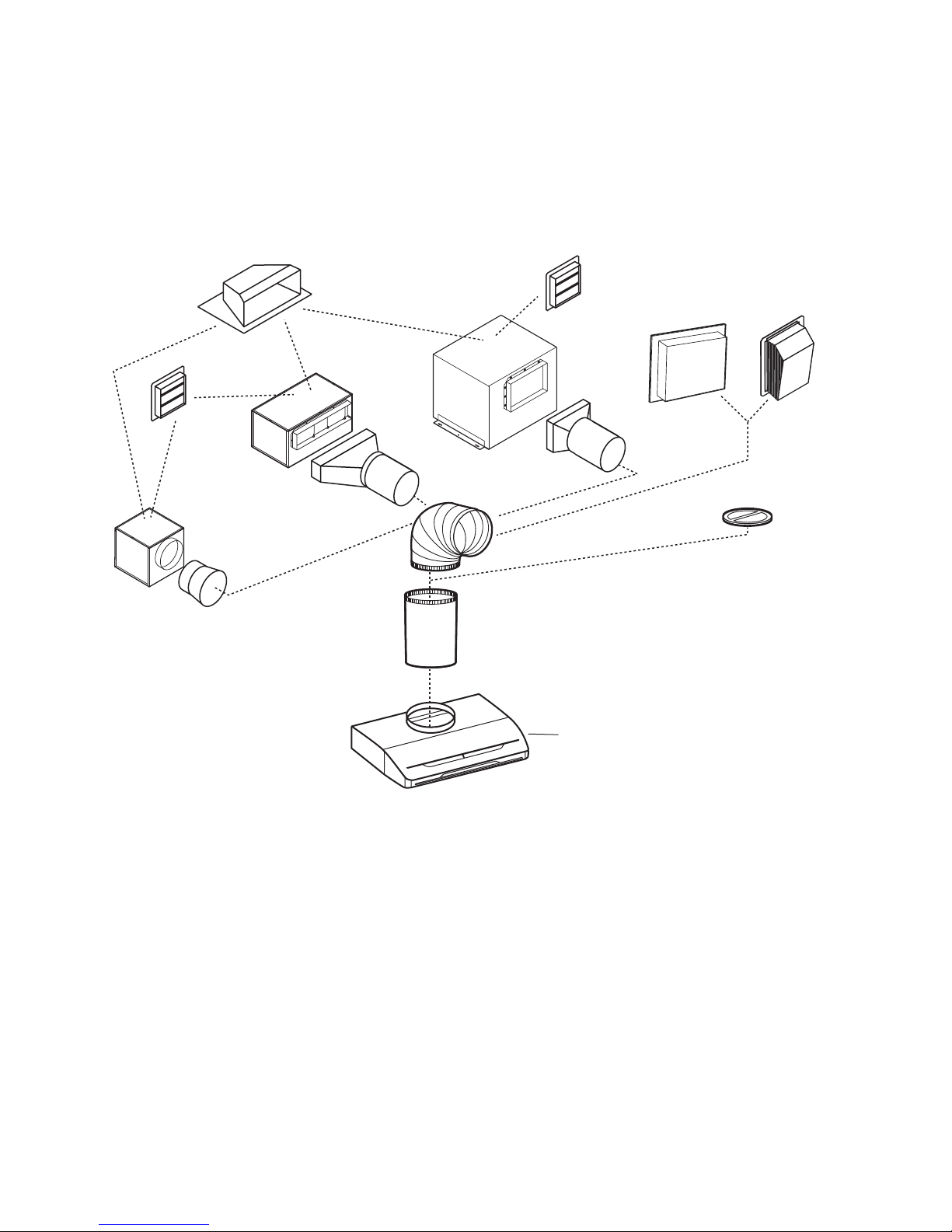
Model 418
10” Rd
adjustable elbow
(optional)
Model HLB3 (280 cfm)
in-line blower
(includes one 8” to 10”
round transition)
BROAN ELITE E662E
BROAN ELITE E662E
HOOD SYSTEM
Model 331H (600 cfm)
or 332H (900 cfm)
exterior blower
Model 335 (1200 cfm)
or 336 (1500 cfm)
exterior blower
Model 441
(10” Rd wall cap)
Model 437
(High capacity roof cap)
Model 441
(10” Rd wall cap)
Model 421
(10” Rd. vert.
in-line damper)
Recommended
for use with
exterior blowers
Model 410
(10” Rd duct
- 2 ft. sections)
Model HLB6 (600 cfm)
in-line blower
(includes two 4½” x 18½”
to 10’’ round transitions)
Model HLB9 (800 cfm)
or HLB11 (1100 cfm)
in-line blower
(includes two 8” x 12” to
10’’ round transitions)
HL0069
Page 5

- 2 -
1. SELECT BLOWER OPTION AND INSTALL DUCTWORK
Either an in-line or exterior blower may be used with this hood. The Broan Elite model E662E must be installed with
blower models HLB3, HLB6, HLB9, HLB11, 331H, 332H, 335 or 336 only. Other blowers cannot be substituted.
(Blowers sold separately).
Plan where and how the ductwork will be installed.
If installing in-line blower, refer to instructions packed with in-line blower and follow steps 1 up to 6, 8 and up
of this manual.
Install proper-sized ductwork, elbows and roof or wall cap for the type of blower you are installing. Use 10’’ round
ductwork. Use 2” duct tape to seal duct joints.
The minimum hood distance above cooktop must not be less than 24”. A maximum of 30” above cooktop is
highly recommended for best capture of cooking impurities.
Distances over 30” are at the installer and users discretion.
MODEL 331H, 332H, 335 OR 336
EXTERIOR BLOWER
TYPICAL DUCTWORK
MODEL HLB3, HLB6, HLB9 OR
HLB11 IN-LINE BLOWER
TYPICAL DUCTWORK
Hood
10" round duct
Exterior blower
HH0047A
24" minimum above
cookingsurface
In-line blower
10” round duct
HH0059A
24” minimum
above
cooking surface
Roof cap
Wall
cap
Hood
2. PREPARE THE INSTALLATION
Make sure that the following items are included:
- Hood
- Accessories:
• Filters (2 for 30’’ and 36’’ width hoods, 3 for 42’’ width hood)
• Bag of parts (inside one filler) including:
(2) wire clamps, (5) no. 8 x 1/2” screws, (3) wire connectors, (9) no. 8 x 3/8” screws
Parts sold separately:
- In-line blower HLB3, HLB6, HLB9 or HLB11 (all include transition)
- Exterior blower model 331H, 332H, 335 or 336
- Halogen lights (MR16, GU10, 120V, 50W)
- Ducts, elbows, dampers, wall and roof caps. Refer to page 1 for a complete list of venting options and model numbers.
NOTES: 1.During installation, protect countertop and/or cooktop.
2. If the bottom of the cabinet is recessed, attach three 1’’ width wood strip (not included). Refer to figure below
for wood strips proper location.
HO0045A
CABINET BOTTOM
’’¾1’’¾1
10¼’’
1”
1”
1”
Page 6
- 3 -
3. CABINET PREPARATION
WARNING
The cabinet must support the total weight of the hood. For the E662E hood model, the total weight
is 20 lb (9 kg).
!
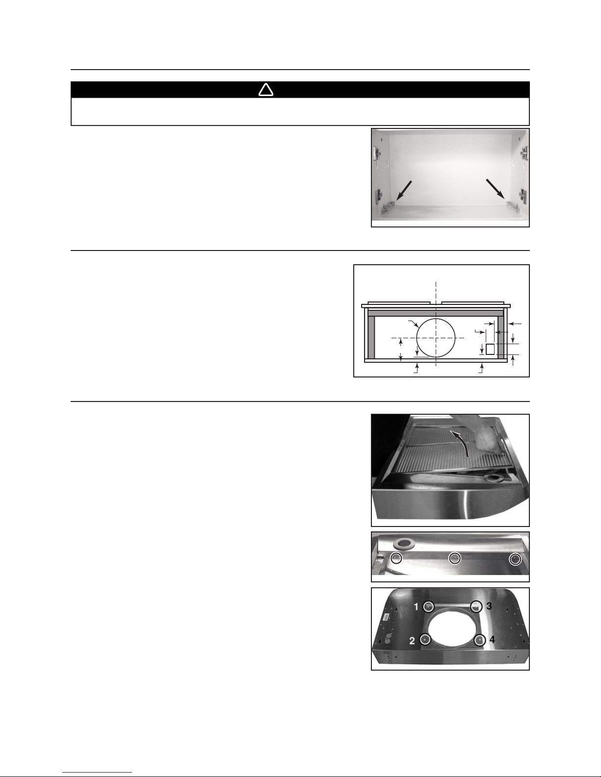
If the cabinet needs to be reinforced, add wood blocks to strengthen the
connection between the bottom of the cabinet and its sides, as shown
beside.
See figure beside for cut-out dimensions in the bottom of the cabinet.
4. CUTTING HOLES
5.1 Pull latch tabs and remove filters from the hood.
HD0139
ADD WOOD BLOCKS
5. PREPARE THE HOOD
HD0133
5.2 Remove (3) screws holding both side panels to the hood and set aside.
HO0042
5.3 Remove (4) screws retaining the rough-in plate from the top of the hood
and set aside.
5.4 Punch out 2 knock-out holes for electrical connections (2 on top or one on top and one on back of the hood). Install
the wire clamps.
HD0134
1
2
3
HH0041A
CABINET BOTTOM
10” dia.
5 7/8”
7/8’’
C
L
1½”
1¼’’
2”
4½”
Page 7
- 4 -
6. INSTALL THE HOOD
7. INSTALL BLOWER
EXTERIOR BLOWER: Refer to instructions packed with exterior blower.
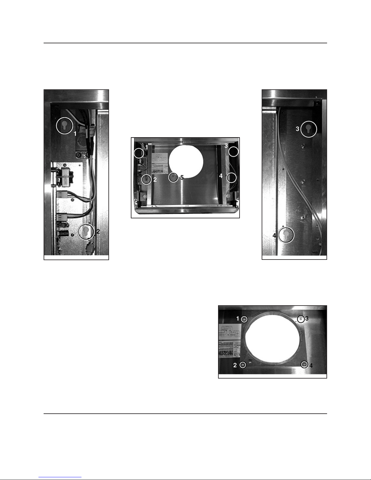
6.1 Run power cable to installation location. Position the hood in its intended location. Using a pen, mark the position
of the screws smaller part of the keyholes, see pictures below for the (5) keyhole locations). Remove the hood.
6.3 Insert the power cable in the hood and tighten the wire clamp to secure the cable. Place the hood under the
cabinet and slide it in position. Tighten the (4) screws completely, then add the last screw (screw no. 5) in the
center keyhole.
6.4 Turn the rough-in plate upside down and use the (4) screws
(previously removed in step 5.3) to install it inside the hood.
6.2 Install (4) no. 8 x 1/2” screws, leaving a 1/8’’ gap (do not install the no. 5 screw yet).
HD0138
HD0137
HD0136
HD0135
Page 8
- 5 -
8. CONNECT WIRING (ALL BLOWERS)
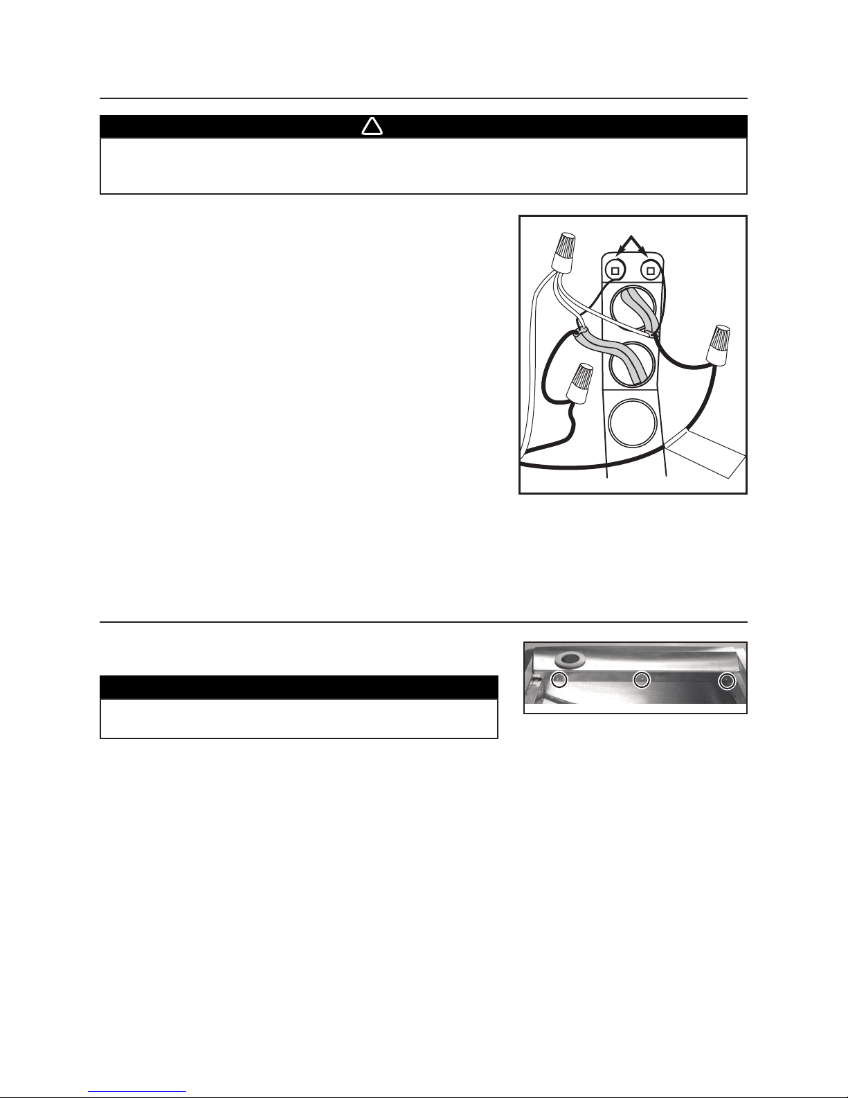
Connect cable into wiring box using provided wire connectors.
Connect wires as follow: WHITE to WHITES (A), BLACK WIRE WITH
YELLOW TAG from hood to BLACK wire from blower cord (B), two others
BLACK together (C) and GREEN or BARE wires under GREEN ground
screws (D). DO NOT FORGET TO CONNECT THE GROUND.
WARNING
Risk of electrical shock. Electrical wiring must be done by qualified personnel in accordance with
all applicable codes and standards. Before connecting wires, switch power off at service panel
and lock service disconnecting means to prevent power from being switched on accidentally.
!
9. REINSTALL SIDE PANELS
Reinstall filters.
Reinstall both side panels, using 3 screws (removed from step 5) per side,
as shown beside.
HO0042
1
2
3
CAUTION
Remove protective plastic film covering filters before
installing them.
D
A
C
HE0050
B
Page 9
- 6 -
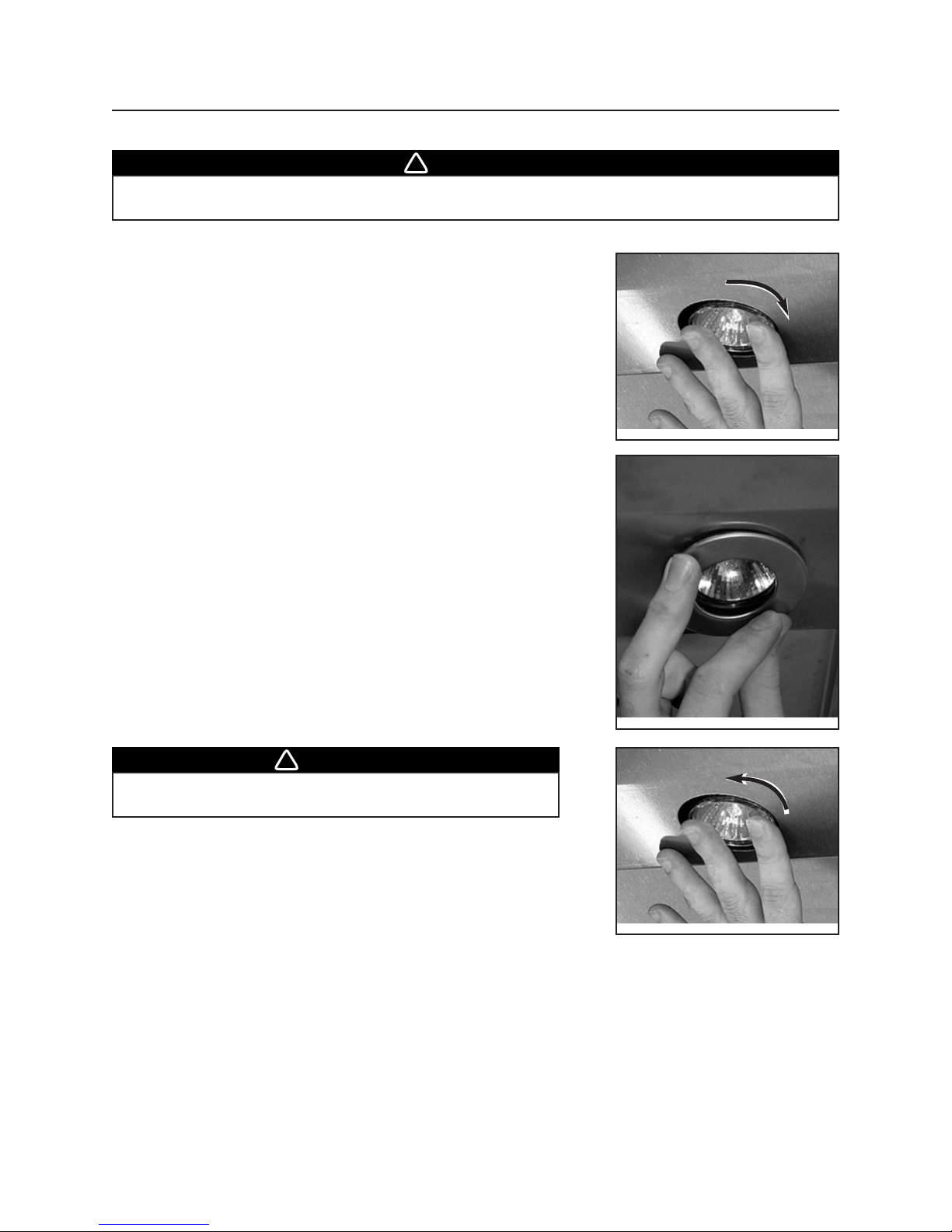
10. LIGHT BULBS
This hood must use 120V, 50W max., type MR16 GU10 shielded halogen lamps. (Purchase separately).
NOTE: The rings must be removed from bottom banel before installing halogen lamps.
WARNING
In order to prevent the risk of personal injury, do not install a lamp identified for use only in
enclosed fixtures.
!
WARNING
In order to prevent the risk of personal injury, the halogen
lamps must be cooled down before removing them.
!
10.1 Install the lamps by placing the bulb leads into their grooves in the socket
and gently push upward and turn clockwise until secured.
HE0047
10.3 To remove lamps, gently push upwad and turn counterclockwise to
disengage bulb leads from their grooves.
HE0047
10.2 Install trim rings by pushing upward.
HO0034
Page 10
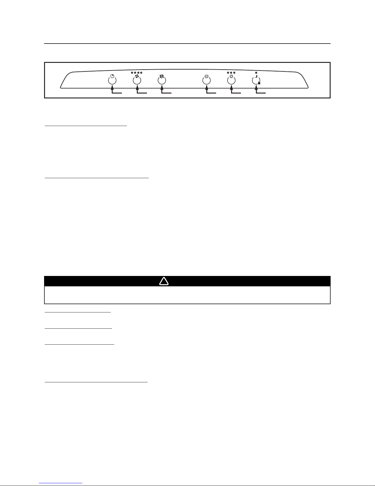
11. OPERATION
A. BLOWER OFF DELAY TOUCH PA D:
When a speed is selected, touch the delay touch pad to activate the delay function. The corresponding speed indicator
LED will start flashing to indicate this function is activated. Touch once for a 5-minute delay, twice for 10-minute delay,
three times for 15-minute delay and four times for a 20-minute delay. The fan will continue to operate for the
programmed minutes and will stop automatically. To cancel the delay function, wait 2 seconds and touch the delay
touch pad once again; the blower will then work in normal mode.
NOTE: The blower speed can be increased - or decreased - during delay mode without starting another delay cycle.
B. ON / B
LOWER SPEED CONTROL TOUCH PAD :
Touch this touch pad to turn on the blower at the last selected speed. To change the blower speed, touch the touch pad
again until the desired speed is obtained.
NOTES: 1. Each time you touch on the speed control touch pad, the speed changes by increments of 1 (e.g.: speed
1 to speed 2, to speed 3, and then speed 4. From the fourth speed, goes down to speed 1).
2. The last speed used is kept in memory except the fourth, the next time the blower will be turned on, it will
run on speed 3.
C. OFF B
LOWER TOUCH PAD :
Touch this touch pad to turn off the blower.This command also cancels the delay function (if activated).
D. OFF L
IGHTING TOUCH PA D:
Touch this touch pad to turn off lighting.
E. H
ALOGEN LIGHT TOUCH PAD :
Touch this touch pad to turn on the halogen lamps. The lighting intensity changes by increments of 1 (e.g.: Touch once for low
intensity, once again to get more, up to three times. From the higher intensity, touch once to go back to the lower intensity).
NOTE: The last lighting intensity used is kept in memory. The next time the halogen lamps will be turned on, they will
light with the last intensity used.
F. N
IGHTLIGHT / KEYBOARD LOCK TOUCH PAD :
Touch this touch pad to activate the nightlight. The LED will light to indicate the nightlight is on.
When cleaning the hood, use the keyboard lock. To activate the keyboard lock, touch on this touch pad during 3 seconds;
the LED will flash to indicate the keyboard lock is on. Touch on the touch pad and hold for 3 seconds again to stop the
keyboard lock function.
NOTES: 1. When cleaning the hood, never spray cleaning agent directly on the controls; spray it on the cleaning
cloth and wipe the control with it. Spraying cleaning agent directly on the control will cause
unexpected keyboard activation.
2. When the keyboard lock is on, it stops the HEAT SENTRY.
3. If there a temporary power failure when the keyboard lock is on, when the power will be restored, the
keyboard lock will still be on.
A) Blower OFF Delay touch pad D) OFF lighting touch pad
B) ON / Blower speed touch pad E) Halogen light touch pad
C) OFF Blower touch pad F) Nightlight / keyboard lock touch pad
Always turn your blower on before you begin cooking to establish an air flow in the kitchen. Allow the blower run for a
few minutes to clear the air after you turn off the range.
HEAT SENTRY
This hood is equipped with a Heat Sentry thermostat. This thermostat is a device that will turn on or speed up the blower
if it senses excessive heat above the cooking surface.
1) If blower is OFF - it turns blower ON to HIGH speed.
2) If blower is ON at a lower speed setting – it turns the blower up to HIGH speed.
When HEAT SENTRY is activated, the first and the last speed blower LEDs are flashing alternately.
When the temperature level drops to normal, the blower will return to its original setting.
WARNING
The HEAT SENTRY can start the blower even if the hood is turned OFF. In this case, it is impossible to
turn the blower OFF with blower switch. If you must stop the blower, do it from the main electrical panel.
!
- 7 -
HC0017
A
B C D E F
Page 11
- 8 -
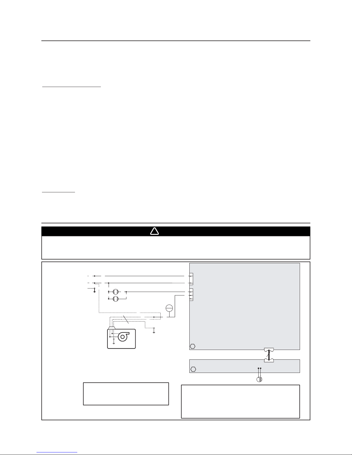
13. WIRING DIAGRAM
12. USE AND CARE
Grease filters and side panels.
The grease filters and the side panels should be cleaned frequently. Use a warm detergent solution.
Remove grease filters by pushing them towards the back of hood and rotating downward.
When cleaning the hood, never spray cleaning agent directly on the controls; spray it on the cleaning cloth and
wipe the control with it. Spraying cleaning agent directly on the control will cause unexpected keyboard activation.
S
TAINLESS STEEL CLEANING:
Do: - Regularly wash surfaces with clean cloth or rag soaked with warm water and mild soap or liquid dish detergent.
- Always clean in the direction of original polish lines.
- Always rinse well with clear water (2 or 3 times) after cleaning. Wipe completely dry.
- You may also use a specialized household stainless steel cleaner.
Don’t: - Do not use any steel or stainless steel wool or any other scrapers to remove stubborn dirt.
- Do not use any harsh or abrasive cleasers.
- Do not allow dirt to accumulate.
- Do not let plaster dust or any construction residues reach the hood. During construction or renovation, cover
the hood to make sure no dust sticks to stainless steel surface.
Avoid: when choosing a detergent
- Any cleaners that contain bleach will attack stainless steel.
- Any products containing : chloride, fluoride, iodide, bromide will deteriorate surfaces rapidly.
- Any combustible products used for cleaning such as acetone, alcohol, ether, benzol, etc., are highly explosive
and should never be used close to a range.
P
AINTED FINISH:
Clean with warm water and mild detergent only. If discoloration occurs, use a good enamel polish such as automotive
polish. (DO NOT use rough abrasive cleaner or porcelain cleaner).
WARNING
Risk of electrical shock. Electrical wiring must be done by qualified personnel in accordance with
all applicable codes and standards. Before connecting wires, switch power off at service panel
and lock service disconnecting means to prevent power from being switched on accidentally.
!
Line 120 V
Supply
Neutral
Ground
HE0044A
BK
BK
W
W
Light Socket
50W max.
W
W
W
REMOTE BLOWER
WIRING COLOR CODE
BK BLACK
W WHITE
Y
Y
Light Socket
50W max.
W
BK
3
Y YELLOW
nc no connection
Note
3
BK
W
J5
3
BK
nc
2
1
W
J6
3
Y
2
BK
1
ELECTRONIC
ASSEMBLY
A1
Main power board
ELECTRONIC
ASSEMBLY
A2
User Interface
-t°
J2
16
Heat Sentry
NOTES
1. If any of the original wire, as supplied, must be replaced, use the
same equivalent wire.
2. Field wiring must comply with applicable codes, ordinances and
regulations.
3. Marked black conductor, for blower wiring.
Page 12

KEY PART WIDTHS
NO. NUMBER
DESCRIPTION
30’’36’’ 42’’
- 9 -
SERVICE PARTS
E662E MODEL
CONTROL FASCIA
CONTROL PCB
ROUGH-IN PLATE
BROAN ELITE LOGO
LAMP SOCKET
CONTROL PROCESSOR UNIT
TRIM RING
FILTERS 9.922’’
X 17.981’’
FILTERS 12.922’’
X 17.981’’
HALOGEN LAMP 50W, 120V, GU-10
LOW VOLTAGE HARNESS
LOW VOLTAGE HARNESS
LOW VOLTAGE HARNESS
HARNESS KIT
INSTALLATION MANUAL
PARTS BAG ((2) wire clamps, (3) wire
connectors, (5) no. 8 x 1/2” screws,
(9) no. 8 x 3/8” screws)
1
2
3
4
5
6
7
8
9
*
*
*
*
V06262
V06263
V06777
V06750
V05917
V06749
V06268
V06265
V06266
V05921
V06734
V06745
V06746
V06744
V06832
V03888
111
111
111
111
222
111
222
2-3
-2222
1--
-1-
--1
111
111
111
* Item not shown.
5
9
1
2
3
5
4
9
6
HL0057
7
8
7
Page 13

CONÇUS POUR LA CUISSON DOMESTIQUE SEULEMENT
INSTALLATEUR : LAISSER CE GUIDE AU PROPRIÉTAIRE.
PROPRIÉTAIRE : INSTRUCTIONS D’UTILISATION ET D’ENTRETIEN EN PAGES 19 ET 20.
LIRE ET CONSERVER CES INSTRUCTIONS
!
!
MODÈLE E662E
Broan-NuTone LLC, 926 West State Street, Hartford, WI 53027 (1-800-637-1453)
NuTone Inc., 4820 Red Bank Road, Cincinnati, OH 45227 (1-800-543-8687)
Broan-NuTone Canada Inc., 1140 Tristar Drive, Mississauga, ON L5T 1H9 (1-888-882-7626)
ENREGISTREZ VOTRE PRODUIT EN LIGNE À : www.broan.com/register
V06832 rév. E
GUIDE D’INSTALLATION
HB0037
Page 14

- 11 -
AVERTISSEMENT AVERTISSEMENT
AFIN DE RÉDUIRE LES RISQUES D’INCENDIE,
D’ÉLECTROCUTION OU DE BLESSURES CORPORELLES,
SUIVEZ LES INSTRUCTIONS SUIVANTES :
1. N’utilisez cet appareil que de la façon prévue par
le manufacturier. Si vous avez des questions,
contactez le manufacturier à l’adresse et au
numéro de téléphone indiqués sur la garantie.
2. Avant de réparer ou de nettoyer l’appareil, couper
l’alimentation électrique en verrouillant le panneau de
service afin d’éviter sa remise en marche accidentelle.
Si le panneau de service ne peut être verrouillé, y
fixer un avertissement en évidence.
3. Les travaux d’installation et de raccordement
électrique doivent être effectués par une personne
qualifiée, conformément aux codes et standards de
construction, incluant ceux concernant les incendies.
4. Une quantité d’air adéquate est requise afin d’assurer
une bonne combustion et l’évacuation des gaz par
la cheminée dans le cas des équipements alimentés
au gaz, afin de prévenir les retours de cheminée.
Conformez-vous aux instructions et aux standards
de sécurité des manufacturiers d’équipement de
chauffage, tel que publiés par la
National Fire
Protection Association
(NFPA), et l’
American
Society for Heating, Refrigeration and Air
Conditioning Engineers
(ASHRAE), ainsi que les
responsables des codes locaux.
5. Lorsque vous coupez ou perforez un mur ou un
plafond, prenez garde de ne pas endommager
les fils électriques ou les autres éléments utilitaires
qui s’y trouvent.
6. L’évacuation des ventilateurs avec conduits doit
toujours se faire à l’extérieur.
7. Ne pas utiliser cet appareil avec une commande
de vitesse à semiconducteur.
8. Afin de réduire les risques d’incendie, n’utilisez
que des conduits de métal.
9. Cet appareil doit être mis à la terre.
AFIN DE RÉDUIRE LES RISQUES DE FEU
DE CUISINIÈRE :
a) Ne jamais laisser les appareils de cuisson sans
surveillance lorsqu’ils sont réglés à feu vif. Les
débordements engendrent de la fumée et des
déversements graisseux pouvant s’enflammer.
Chauffez l’huile lentement, à feu doux ou moyen.
b) Toujours mettre la hotte en marche lorsque vous
cuisinez à feu vif ou que vous cuisinez des
mets flambés.
c) Nettoyez régulièrement la (les) roue(s) du ventilateur.
Ne laissez pas la graisse s’accumuler sur le ventilateur
ou les filtres.
d) Utilisez le bon format de casserole. Servez-vous
toujours de casseroles et d’ustensiles appropriés à
la dimension de la surface chauffante.
AFIN D’ÉVITER TOUT RISQUE DE BLESSURES LORS
D’UN FEU DE CUISINIÈRE, SUIVEZ CES INSTRUCTIONS* :
1. Étouffez les flammes avec un couvercle hermétique,
une tôle à biscuits ou un plateau métallique et
ensuite, éteindre le brûleur. PRENEZ SOIN
D’ÉVITER LES BRÛLURES. SI LES FLAMMES
NE S’ÉTEIGNENT PAS IMMÉDIATEMENT,
ÉVACUEZ LES LIEUX ET APPELEZ LES POMPIERS.
2. NE PRENEZ JAMAIS UNE CASSEROLE EN
FLAMMES DANS VOS MAINS – Vous pourriez
subir des brûlures.
3. N’UTILISEZ PAS D’EAU, incluant linge à vaisselle
ou serviette mouillés – ceci pourrait occasionner
une violente explosion.
4. N’utilisez un extincteur QUE DANS LE CAS OÙ :
A. Vous savez qu’il s’agit d’un extincteur de classe ABC
et que vous en connaissez le fonctionnement.
B. L’incendie est petit et limité à l’endroit où il a débuté.
C. Les pompiers ont été avisés.
D. Vous pouvez combattre l’incendie en ayant
accès à une sortie de secours.
*Tirées du
Kitchen Fire Safety Tips
publié par la NFPA.
ATTENTION
1. Pour usage domestique seulement. Ne pas utiliser pour
évacuer des vapeurs ou des produits dangereux ou explosifs.
2. Afin d’éviter tout dommage au moteur et de débalancer
ou de rendre bruyante la roue du moteur, garder votre
appareil à l’abri des poussières de placoplâtre
et de construction/rénovation, etc.
3. Le moteur de votre hotte possède une protection
thermique qui éteindra automatiquement le moteur s’il
devient surchauffé. Le moteur repartira automatiquement
une fois refroidi. Si le moteur continue à arrêter et
à repartir, faites-le vérifier.
4. La distance minimale entre le bas de votre hotte et
la surface de cuisson ne doit pas être plus petite
que 24 po. Un maximum de 30 po au dessus de la
surface de cuisson est fortement recommandé
pour une meilleure évacuation des odeurs de cuisine.
5. Deux installateurs sont recommandés lors de
l’installation vu la grande dimension et le poids de
cet appareil.
6. Afin de réduire les risques d’incendie, assurez-vous
d’évacuer l’air à l’extérieur – Ne pas évacuer l’air dans
des espaces restreints comme l’intérieur des murs ou
plafond ou dans le grenier, faux plafond ou garage.
7. Cet appareil est équipé d’un thermostat pouvant
faire démarrer le ventilateur automatiquement. Afin
de réduire le risque de blessure, couper le courant à
partir du panneau électrique et verrouiller ou apposer
un avertissement sur le panneau afin de prévenir
que la hotte soit mise en marche automatiquement.
8. À cause de la grande capacité d’évacuation de cet
appareil, il est recommandé d’ouvrir une fenêtre dans
ou près de la cuisine afin de remplacer l’air évacué.
9. Afin de réduire les risques d’incendie et d’électrocution,
la hotte de modèle Broan Elite E662E doit être
installée uniquement avec un des ventilateurs en
ligne Broan suivants : HLB3, HLB6, HLB9 ou HLB11,
ou un des ventilateurs extérieurs Broan suivants :
331H, 332H, 335 ou 336 (vendus séparément).
Aucun autre ventilateur ne doit être utilisé.
10. Cette hotte ne doit être utilisée seulement qu’avec
un ensemble de cordon d’alimentation approuvé.
11. Veuillez consulter l’autocollant apposé à l’intérieur du
produit pour plus d’information ou autres exigences.
!
!
Page 15

- 12 -
TABLE DES MATIÈRES
SYSTÈME DE HOTTE BROAN ELITE E662E . . . . . . . . . . . . . . . . . . . . . . . . . . . . . . . . . . . . . . . . . .13
1. SÉLECTIONNER L’OPTION VENTILATEUR ET INSTALLER LES CONDUITS . . . . . . . . . . . . . . . . . . . . . . . . .14
2. PRÉPARATION DE L’INSTALLATION . . . . . . . . . . . . . . . . . . . . . . . . . . . . . . . . . . . . . . . . . . . . . . . . . .14
3. P
RÉPARATION DE L’ARMOIRE . . . . . . . . . . . . . . . . . . . . . . . . . . . . . . . . . . . . . . . . . . . . . . . . . . . . .15
4. DÉCOUPE DES TROUS . . . . . . . . . . . . . . . . . . . . . . . . . . . . . . . . . . . . . . . . . . . . . . . . . . . . . . . . .15
5. PRÉPARATION DE LA HOTTE . . . . . . . . . . . . . . . . . . . . . . . . . . . . . . . . . . . . . . . . . . . . . . . . . . . . .15
6. I
NSTALLATION DE LA HOTTE . . . . . . . . . . . . . . . . . . . . . . . . . . . . . . . . . . . . . . . . . . . . . . . . . . . . .16
7. I
NSTALLATION DU VENTILATEUR . . . . . . . . . . . . . . . . . . . . . . . . . . . . . . . . . . . . . . . . . . . . . . . . . . .16
8. BRANCHEMENT ÉLECTRIQUE (TOUS LES VENTILATEURS) . . . . . . . . . . . . . . . . . . . . . . . . . . . . . . . . .17
9. RÉINSTALLER LES PANNEAUX LATÉRAUX . . . . . . . . . . . . . . . . . . . . . . . . . . . . . . . . . . . . . . . . . . . . .17
10. LAMPES HALOGÈNES . . . . . . . . . . . . . . . . . . . . . . . . . . . . . . . . . . . . . . . . . . . . . . . . . . . . . . . . .18
11. F
ONCTIONNEMENT . . . . . . . . . . . . . . . . . . . . . . . . . . . . . . . . . . . . . . . . . . . . . . . . . . . . . . . . . .18
12. ENTRETIEN . . . . . . . . . . . . . . . . . . . . . . . . . . . . . . . . . . . . . . . . . . . . . . . . . . . . . . . . . . . . . . .19
13. SCHÉMA ÉLECTRIQUE . . . . . . . . . . . . . . . . . . . . . . . . . . . . . . . . . . . . . . . . . . . . . . . . . . . . . . . .19
14. PIÈCES DE REMPLACEMENT . . . . . . . . . . . . . . . . . . . . . . . . . . . . . . . . . . . . . . . . . . . . . . . . . . . .20
GARANTIE
GARANTIE LIMITÉE D’UN AN DE BROAN-NUTONE LLC
Broan-NuTone LLC garantit à l’acheteur consommateur initial de ses produits qu’ils sont exempts de tout défaut dans les
matières premières ou la main-d’œuvre, pour une période d’un an à compter de la date d’achat par le consommateur
initial. IL N’Y A PAS D’AUTRES GARANTIES, EXPRIMÉES OU IMPLICITES, INCLUANT, MAIS NON LIMITÉES AUX
GARANTIES IMPLICITES POUR FIN DE COMMERCIALISATION ET DE CONVENANCE DANS UN BUT PARTICULIER.
Durant cette période d’un an, Broan-NuTone LLC, à sa discrétion, réparera ou remplacera gratuitement, tout
produit ou pièce qui s’avère défectueux et ayant été utilisé nomalement et d'une manière non abusive.
Cette garantie ne couvre pas (a) l’entretien et le service normal ou (b) tout produit ou pièce endommagé par suite
de mauvais usage, négligence, accident, entretien inapproprié ou réparation (autre que par Broan-NuTone LLC),
mauvaise installation ou installation non conforme au mode d’installation recommandé.
La durée de toute garantie implicite est limitée à une période d’un an tel que spécifiée pour la garantie exprimée.
Certains états ou provinces ne permettent pas de limite de temps sur les garanties implicites. Si tel est le cas,
veuillez ne pas tenir compte de la dernière limite décrite ci-dessus.
L’ENGAGEMENT DE BROAN-NUTONE LLC DE RÉPARER OU DE REMPLACER, AU CHOIX DE BROAN-NUTONE LLC,
SERA LA SEULE OBLIGATION EXCLUSIVE SOUS CETTE GARANTIE. BROAN-NUTONE LLC NE SE TIENDRA
PAS RESPONSABLE DES DOMMAGES DIRECTS, INDIRECTS OU SPÉCIAUX SURVENANT À CAUSE DE OU
EN RAPPORT À L’UTILISATION OU LA PERFORMANCE DE SES PRODUITS. Certains états ou provinces ne
permettent pas l’exclusion ou la limite relative aux dommages directs, indirects ou spéciaux. Si tel est le cas,
veuillez ne pas tenir compte de l’exclusion ou de la limite ci-dessus.
Cette garantie vous donne des droits légaux spécifiques et il se peut que vous ayez d’autres droits qui varient d’un
état ou d’une province à l’autre. Cette garantie annule toutes les autres garanties précédentes.
Pour le service sous garantie, vous devez (a) aviser Broan-NuTone LLC à l’adresse ou numéro de téléphone mentionnés
plus bas, (b) donner le numéro du modèle et l’identification de la pièce et (c) décrire la nature de tout défaut dans
le produit ou la pièce. Au moment de la demande de service sous garantie, vous devez présenter une preuve de
la date d’achat initial du dit produit.
Broan-NuTone LLC, 926 West State Street, Hartford, WI 53027 (1-800-637-1453)
NuTone Inc., 4820 Red Bank Road, Cincinnati, OH 45227 (1-800-543-8687)
Broan-NuTone Canada Inc., 1140 Tristar Drive, Mississauga, ON L5T 1H9 (1-888-882-7626)
Page 16

- 13 -
Modèle 421
(Volet intérieur
10 po rond vert.)
Recommandé
pour utilisation
avec ventilateurs
extérieurs
Modèle 410
(Conduit de 10 po rond
standard section de 2 pi)
Modèle 418
Coude ajustable de
10 po (optionnel)
Ventilateur en ligne
modèle HLB3 (280 pcm)
(incluant une transition
ronde 8 po à 10 po)
Ventilateur extérieur
modèle 331H (600 pcm)
ou 332H (900 pcm)
Ventilateur extérieur
modèle 335 (1200 pcm)
ou 336 (1500 pcm)
Modèle 441
(Capuchon de
mur 10 po rond)
Modèle 441
(Capuchon de
mur 10 po rond)
Ventilateur en ligne modèle
HLB6 (600 pcm)
(incluant deux transitions
rondes de 4½ po x 18½ po
à 10 po)
Ventilateur en ligne
modèle HLB9 (800 pcm)
ou HLB11 (1100 pcm)
(incluant deux transitions
rondes de 8 po x 12 po
à 10 po)
BROAN ELITE E662E
SYSTÈME DE HOTTE
BROAN ELITE E662E
Modèle 437
(Capuchon de toit
haut rendement)
HL0069
Page 17

1. SÉLECTIONNER L’OPTION VENTILATEUR ET NSTALLER LES CONDUITS
Cette hotte fonctionne autant avec un ventilateur en ligne qu’avec un ventilateur extérieur. La hotte Broan Elite de
modèle E662E doit être installée uniquement avec l’un des ventilateurs suivants : HLB3, HLB6, HLB9, HLB11, 331H,
332H, 335 ou 336 (vendus séparément). Aucun autre ventilateur ne peut être utilisé.
Déterminer à quel endroit et de quelle façon les conduits seront installés.
Si un ventilateur en ligne est installé, se reporter aux directives incluses avec celui-ci et suivre les étapes 1 à
6, 8 et suivantes de ce guide.
Installer des conduits de format adéquat, coude(s) et capuchon de mur ou de toit selon le type de ventilateur. Utiliser des
conduits circulaires de 10 po. Utiliser du ruban adhésif en toile de 2 po de largeur pour assurer l’étanchéité des joints.
La distance minimale entre le bas de votre hotte et la surface de cuisson ne doit pas être plus petite que 24 po.
Un maximum de 30 po au-dessus de la surface de cuisson est fortement recommandé pour une meilleure
évacuation des odeurs de cuisine.
Une distance de plus de 30 po demeure à la discrétion de l’installateur et de l’utilisateur.
- 14 -
2. PRÉPARER L’INSTALLATION
S’assurer que les items suivants sont inclus :
- Hotte
- Accessoires :
• Filtres (3 pour une hotte de 30 po ou 36 po de largeur, 4 pour une hotte de 42 po de largeur)
• Sac de pièces (à l’intérieur d’un embout en styromousse) incluant :
(2) serre-fils, (5) vis n° 8 x 1/2 po, (3) connecteurs et (9) vis n° 8 x 3/8 po
Pièces vendues séparément :
- Ensemble ventilateur en ligne modèles HLB3, HLB6, HLB9 ou HLB11 (tous incluant la transition)
- Ensemble ventilateur extérieur modèles 331H, 332H, 335 ou 336
- Ampoules halogènes (MR16, GU10, 120V, 550W)
- Transitions, conduits, coudes, volets, capuchons de mur ou de toit. Consuler la page 13 pour la liste complète des
accessoires de ventilation et les numéros de modèle.
NOTES :1. Lors de l’installation, protéger la table de cuissson et/ou le comptoir de cuisine.
2. Si le fond de l’armoire est en retrait, fixer 3 languettes de bois de 1 po de largeur (non inclusess) pour combler
l’espace afin de bien retenir la hotte à l’armoire. Voir ci-dessous pour le positionnement des languettes.
INSTALLATION TYPIQUE AVEC
VENTILATEUR EXT. MODÈLE
331H, 332H, 335 OU 336
INSTALLATION TYPIQUE AVEC
VENTILATEUR EN LIGNE MODÈLE
HLB3, HLB6, HLB9 OU HLB11
Hotte
Conduit rond
de 10 po
Ventilateur extérieur
HH0047F
24 po minimum
au-desus de la
table de cuisson
HH0059F
Capuchon
de toit
Hotte
Ventilateur
en ligne
Conduit rond
de 10 po
Minimum de
24 po au-dessus
de la table
de cuisson
Capuchon
de mur
DESSOUS D’ARMOIRE
po¾1 po¾1
10¼ po
1 po
1 po
1 po
Page 18

- 15 -
3. PRÉPARATION DE L’ARMOIRE
AVERTISSEMENT
L’armoire doit être conçue de façon à pouvoir supporter le poids total de la hotte, qui est de 20 lb
(9 kg).
!
Si l’armoire doit être renforcée, il est suggéré d’ajouter des blocs de bois afin
de solidifier le joint entre le bas de l’armoire et ses côtés, tel qu’illustré
ci-contre.
Consulter la figure ci-contre pour connaître les dimensions de découpe
des trous dans la base de l’armoire.
4. DÉCOUPE DES TROUS
5.1 Tirer sur le loquet des filtres pour les retirer de la hotte.
HD0139
BLOCS DE BOIS AJOUTÉS
5. PRÉPARATION DE LA HOTTE
HD0133
5.2 Retirer les (3) vis retenant chacun des panneaux latéraux et mettre de
côté. Retirer les 2 panneaux latéraux.
HO0042
5.3 Retirer les (4) vis rattachant la plaque de raccord de conduit au dessus
de la hotte et mettre de côté.
5.4 Défoncer 2 ouvertures pré-amorcées pour le branchement électrique (2 sur le dessus ou 1 sur le dessus et 1 à
l’arrière de la hotte). Installer les serre-fils.
HD0134
1
2
3
HH0041F
DESSOUS D’ARMOIRE
C
L
10” dia.
5 7/8”
7/8’’
1½”
1¼’’
2”
4½”
Page 19

- 16 -
6. INSTALLATION DE LA HOTTE
7. INSTALLATION DU VENTILATEUR
VENTILATEUR EXTÉRIEUR : Suivre les instructions incluses avec le ventilateur extérieur.
6.1 Passer l’alimentation électrique jusqu’à l’endroit de l’installation. Placer la hotte à son emplacement. À l’aide d’un
crayon, marquer la position des vis (petite partie des trous en forme de poire, voir les photos ci-dessous pour la
localisation des (5) trous). Enlever la hotte.
6.3 Passer le fil d’alimentation électrique dans la hotte et serrer le serre-fils pour maintenir le fil en place. Placer la
hotte sous l’armoire et la glisser en position. Visser complètement les (4) vis, puis ajouter la dernière vis (vis n° 5)
dans le trou en forme de poire du centre.
6.4 Retourner la plaque de raccord de conduit et l’assembler par
l’intérieur à la hotte à l’aide des (4) vis retirées précédemment au
point 5.3.
6.2 Visser (4) vis n° 8 x 1/2 po, en laissant un espace de 1/8 po (ne pas installer tout de suite la vis n° 5).
HD0138
HD0137
HD0136
HD0135
Page 20

- 17 -
8. BRANCHEMENT ÉLECTRIQUE (TOUS LES VENTILATEURS)
Connecter les fils à la hotte en utilisant les connecteurs fournis.
Connecter le fil BLANC aux BLANCS (A), le fil NOIR AVEC L’ÉTIQUETTE
JAUNE de la hotte au fil NOIR provenant du ventilateur (B), les deux autres
fils NOIRS ensemble (C) et les fils VERTS ou DÉNUDÉS sous les vis
VERTES de mise à la terre (D).
NE PAS OUBLIER DE CONNECTER LA MISE À LA TERRE.
9. RÉINSTALLER LA PANNEAUX LATÉRAUX
Réinstaller les filtres.
Réinstaller les 2 panneaux latéraux, (3 vis par côtés, retirées à l’étape 5) tel
qu’illustré ci-contre.
HO0042
1
2
3
ATTENTION
Retirer le film de plastique protecteur des filtres avant de
les installer.
AVERTISSEMENT
Risque d’électrocution. Le raccordement électrique doit être effectué par du personnel qualifié
conformément aux codes et standards. Avant d’effectuer le branchement, coupez l’alimentation
électrique au panneau de service et verrouillez-le pour éviter une mise en marche accidentelle.
!
D
A
B
HE0050
C
Page 21

- 18 -
10. LAMPES HALOGÈNES
Cette hotte utilise des ampoules halogènes avec écran de type MR16 GU10, 120 volts, 50W maximum (non incluses).
NOTE : Avant d’installer les lampes halogènes, retirer les anneaux métalliques du panneau inférieur de la hotte.
AVERTISSEMENT
Afin d’éviter le risque de blessures corporelles, ne pas installer une ampoule conçue uniquement
pour des luminaires fermés.
!
AVERTISSEMENT
Afin d’éviter le risque de blessures corporelles, attendre
que l’ampoule halogène soit refroidie avant de la retirer.
!
10.1 Installer les ampoules en glissant leurs conducteurs dans les rainures, à
l’intérieur des douilles. Poussant doucement vers le haut et tourner dans le
sens des aiguilles d’une montre, jusqu’à ce que les ampoules soient bien
en place.
HE0047
10.3 Pour retirer l’ampoule, pousser doucement vers le haut et tourner dans le
sens contraire des aiguilles d’une montre pour dégager les conducteurs
hors de leurs rainures.
HE0047
10.2 Installer les anneaux métalliques en les poussant doucement vers le haut
jusqu’à ce qu’ils soient bien en place.
HO0034
Page 22

- 19 -
11. FONCTIONNEMENT
A. COMMANDE À EFFLEUREMENT D’ARRÊT DIFFÉRÉ :
Lorsque le ventilateur est en marche, effleurer l’icône pour activer la fonction d’arrêt différé. L’indicateur lumineux de
vitesse correspondante commencera à clignoter pour indiquer que la fonction est activée. Effleurer une fois pour un arrêt
dans 5 minutes, 2 fois pour un arrêt dans 10 minutes, 3 fois pour un arrêt dans 15 minutes et 4 fois pour un arrêt dans
20 minutes. Le ventilateur continuera de fonctionner pendant le nombre de minutes programmées puis s’arrêtera
automatiquement. Pour annuler la fonction d’arrêt différé, attendre 2 secondes et effleurer l’icône une autre fois.
NOTE : Lorsque la fonction d’arrêt différé est activée, la vitesse du ventilateur peut être augmentée - ou diminuée -
à l’intérieur du même cycle d’arrêt différé.
B. C
OMMANDE À EFFLEUREMENT DE MISE EN MARCHE / VITESSE DU VENTILATEUR :
Effleurer cet icône pour mettre en marche ce ventilateur; il démarrera à la même vitesse qu’il était réglé avant son dernier
arrêt. Pour changer la vitesse du ventilateur, effleurer à nouveau l’icône jusqu’à l’obtention de la vitesse désirée.
NOTES : 1. À chaque fois que l’on effleure l’icône, la vitesse change par incréments de 1 (ex. : de la vitesse 1, à 2, à
3 et puis à 4. À partir de la quatrième vitesse, on retourne à la première [1]).
2. La dernière vitesse utilisée ests gardée en mémoire. Lorsque l’on active de nouveau le ventilateur, il tourne à la
même vitesse que la dernière fois, sauf pour la quatrième vitesse, où dans ce cas, il tournera en troisième vitesse.
C. C
OMMANDE À EFFLEUREMENT D’ARRÊT DU VENTILATEUR :
Effleurer cet icône pour arrêter le ventilateur et annuler la fonction d’arrêt différé (si activée).
D. C
OMMANDE À EFFLEUREMENT D’ARRÊT DE L’ÉCLAIRAGE :
Effleurer cet icône pour éteindre les lumières de la hotte.
E. C
OMMANDE À EFFLEUREMENT DES LAMPES HALOGÈNES :
Effleurer cet icône pour allumer les lampes halogènes. L’intensité d’éclairage change par incréments de 1
(ex. : Effleurer une fois pour la basse intensité, une autre fois pour un peu plus d’éclairage, jusqu’à trois). De la plus
haute intensité, effleurer une autre fois pour retourner à la plus basse.
NOTE : La dernière intensité lumineuse utilisée est gardée en mémoire. La prochaine fois que l’éclairage sera utilisé,
les lampes halogènes éclaireront à cette même intensité.
F. C
OMMANDE À EFFLEUREMENT VEILLEUSE / CLAVIER VERROUILLÉ :
Effleurer cet icône pour activer l’éclairage en mode veilleuse. Le témoin lumineux s’allumera pour indiquer que ce mode est activé.
Lors du nettoyage de la hotte, utilisser la fonction de verrouillage de clavier. Pour activer cette fonction, effleurer l’icône
durant 3 secondes; le témoin lumineux clignotera pour indiquer que la fonction est activée. Pour déverrouiller le clavier,
effleurer l’icône durant 3 secondes une autre fois.
NOTES : 1. Lors du nettoyage de la hotte, ne jamais vaporiser d’agent nettoyant directement sur le clavier; en
vaporiser plutôt sur un linge et ensuite, essuyer le clavier. Vaporiser un agent nettoyant directement
sur le clavier activera les contrôles.
2. Lorsque la fonction de verrouillage de clavier est activée, la fonction HEAT SENTRY ne fonctionne pas.
3. S’il survient une panne de courant lorsque le clavier est verrouillé, le clavier demeurera verrouillé lorsque
le courant sera rétabli.
A) Commande à effleurement d’arrêt différé D) Commande à effleurement d’arrêt de l’éclairage
B) Commande à effleurement de mise en marche / Vitesse du ventilateur E) Commande à effleurement des lampes halogènes
C) Commande à effleurement d’arrêt du ventilateur F) Commande à effleurement veilleuse / Clavier verrouillé
Toujours mettre en marche le ventilateur avant de commencer la cuisson afin d’établir une circulation d’air dans la
cuisine. Laisser également le ventilateur fonctionner quelques minutes après l’arrêt de la cuisinière afin de nettoyer l’air.
HEAT SENTRY
Cette hotte est équipée d’un capteur de température appelé HEAT SENTRY. Ce capteur mettra en marche automatiquement
le ventilateur ou augmentera sa vitesse s’il détecte de la chaleur excessive au-dessus de la table de cuisson.
1) Si le ventilateur n’est pas en marche - il met le ventilateur en marche à haute vitesse.
2) Si le ventilateur est en marche à une vitesse inférieure – il met le ventilateur en vitesse maximum.
Lorsque le HEAT SENTRY est activé, les indicateurs lumineux de la première et de la dernière vitesse clignotent
alternativement. Lorsque la température revient à la normale, la vitesse du ventilateur retourne à sa position originale.
AVERTISSEMENT
Le HEAT SENTRY peut activer le ventilateur même si la hotte esst arrêtée. Dans ce cas, il est impossible
d’arrêter le ventilateur avec le bouton d’arrêt du ventilateur. Pour éviter que le ventilateur ne démarre,
couper l’alimentation électrique au tableau de distribution principal.
!
HC0017
A
B C D E F
Page 23

- 20 -
12. ENTRETIEN
13. SCHÉMA ÉLECTRIQUE
Filtres et panneaux latéraux.
Les filtres et les panneaux latéraux doivent être nettoyés régulièrement. Utiliser de l’eau chaude additionnée de détergent.
Pour retirer les filtres, tirer sur leurs loquets en les poussant vers l’arrière de la hotte et les désengager de celle-ci.
Lors du nettoyage de la hotte, ne jamais vaporiser d’agent nettoyant directement sur le clavier; en vaporiser plutôt
sur un linge et ensuite, essuyer le clavier. Vaporiser un agent nettoyant directement sur le clavier activera les contrôles.
A
CIER INOXYDABLE : COMMENT MAINTENIR SON APPARENCE ÉTINCELANTE
À faire :
- Laver régulièrement les surfaces à l’aide d’un chiffon ou linge propre imbibé d’eau tiède et de savon doux ou
détergent à vaisselle.
- Toujours nettoyer dans la direction des lignes de grains (direction du polissage).
- Toujours bien rincer avec de l’eau propre (2 ou 3 fois) après le nettoyage et essuyer complètement.
- Un nettoyant domestique conçu spécialement pour l'acier inoxydable peut aussi être utilisé.
À ne pas faire :
- N’utiliser aucune laine d’acier ou d’acier inoxydable ou tout autre grattoir pour enlever la saleté tenace.
- N’utiliser aucune poudre nettoyante abrasive ou rugueuse.
- Ne pas laisser la saleté s’accumuler.
- Ne pas laisser la poussière de plâtre ou tout autre résidu de construction/rénovation atteindre la hotte. Couvrir
l’armoire pour la durée des travaux pour s’assurer qu’aucune poussière ne colle à la surface de l’acier.
À éviter lors du choix d’un détergent :
- Tous produits nettoyants qui contiennent des agents de blanchiment; ils attaqueront l’acier inoxydable.
- Tous produits contenant du chlorure, fluorure, iode ou bromure; ils détérioreront rapidement les surfaces.
- Tous produits combustibles utilisés pour le nettoyage : acétone, alcool, éther, benzène, etc.; ils sont hautement
explosifs et ne devraient jamais être utilisés près d’une cuisinière.
S
URFACES PEINTES :
Nettoyer avec de l’eau chaude additionnée de détergent doux seulement. S’il y a décoloration, utiliser une bonne cire
à peinture telle qu’une cire automobile. (Ne pas utiliser de nettoyant abrasif ou de nettoyant à porcelaine).
AVERTISSEMENT
Risque d’électrocution. Le raccordement électrique doit être effectué par du personnel qualifié
conformément aux codes et standards. Avant d’effectuer le branchement, coupez l’alimentation
électrique au panneau de service et verrouillez-le pour éviter une mise en marche accidentelle.
!
Ligne 120 V
Entrée
Neutre
Mise à
la terre
HE0044F
N
N
B
B
Douille d’ampoule
50W max.
B
B
J
B
Douille d’ampoule
Ventilateur extérieur
CODE DE COULEUR DES FILS
B BLANC
J JAUNE
J
50W max.
B
N
3
NNOIR
sc sans connexion
B
Note
3
N
J5
3
N
sc
2
1
B
J6
3
J
2
N
1
BLOC ÉLECTRONIQUE
A1
Carte d’alimentation principale
BLOC ÉLECTRONIQUE
A2
Interface utilisateur
1. Lors d'un remplacement de fil, utiliser le même type
ou l'équivalent.
2. Les fils installés sur place doivent respecter les codes et
règlements en vigueur.
3. Fil noir avec étiquette, pour branchement du ventilateur.
NOTES
-t°
J2
16
Heat Sentry
Page 24

- 21 -
PIÈCES DE REMPLACEMENT
RÉF. NUMÉRO LARGEURS
N° DE PIÈCE
DESCRIPTION
30 po 36 po42 po
MODÈLE E662E
CLAVIER
CARTE DU CLAVIER
PLAQUE DE RACCORD DE CONDUIT
LOGO BROAN ELITE
DOUILLE D’AMPOULE
UNITÉ DE CONTRÔLE PRINCIPALE
ANNEAU
FILTRES 9,922
PO X 17,981 PO
FILTRES 12,922 PO X 17,981 PO
LAMPE HALOGÈNE 50W, 120V, GU-10
HARNAIS DE BASSE TENSION
HARNAIS DE BASSE TENSION
HARNAIS DE BASSE TENSION
KIT HARNAIS
GUIDE D’INSTALLATION
SAC DE PIÈCES ((2) serre-fils,
(3) connecteurs, (5) vis n° 8 x 1/2 po,
(9) vis n° 8 x 3/8 po)
1
2
3
4
5
6
7
8
9
*
*
*
*
V06262
V06263
V06777
V06750
V05917
V06749
V06268
V06265
V06266
V05921
V06734
V06745
V06746
V06744
V06832
V03888
111
111
111
111
222
111
222
2-3
-2222
1--
-1-
--1
111
111
111
* Non illustré
5
4
9
6
1
2
3
5
9
HL0057
7
8
7
Page 25

INSTRUCCIONES DE INSTALACIÓN
EXCLUSIVAMENTE PARA COCINAS DOMÉSTICAS
INSTALADOR: ENTREGUE ESTE MANUAL AL PROPIETARIO DE LA CASA.
PROPIETARIO: INFORMACIÓN SOBRE UTILIZACIÓN Y CUIDADO EN LAS
PÁGINAS 31 Y 32.
Broan-NuTone LLC, 926 West State Street, Hartford, WI 53027 (1-800-637-1453)
NuTone Inc., 4820 Red Bank Road, Cincinnati, OH 45227 (1-800-543-8687)
Broan-NuTone Canada Inc., 1140 Tristar Drive, Mississauga, ON L5T 1H9 (1-888-882-7626)
REGISTRE SU PRODUCTO EN LÍNEA EN: www.broan.com/register
V06832 rev. E
LEA ESTAS INSTRUCCIONES Y GUÁRDELAS
MODELO E662E
!
!
HB0037
Page 26

- 23 -
ADVERTENCIA ADVERTENCIA
PARA REDUCIR EL RIESGO DE INCENDIO,
DESCARGA ELÉCTRICA, O LESIONES A
PERSONAS, CUMPLA LOS SIGUIENTES PUNTOS:
1. Utilice esta unidade únicamente de la forma en
que indica el fabricante. Si tiene calquier pregunta,
póngase en contacto con el fabricante en la dirección
o el teléfono que aparacen en la garantía.
2. Antes de reparar o limpiar el aparato, apáguelo
en el tablero de servicio y bloquee los medios de
desconexión para impedir que la corriente se
conecte accidentalmente. Cuando no se pueda
bloquear los medios de desconexión, coloque un
dispositivo de advertancia visible (como una tarjeta)
en el tablero de servicio.
3. La instalación y la conexión eléctrica deben ser
realizadas por personal competente de acuerdo
con todos los códigos y las normas aplicables,
incluso los relativos a la construcción igífuga.
4. Para lograr una combustión adecuada y una
extracción correcta de los gases a través de la salida
del humo (chimenea) del equipo quemador de
combustible - evitando así el contratiro - es necesario
disponer de aire suficiente. Siga las directrices del
fabricante del equipo de material térmico y las
normas de seguridad, como las que publica la
NFPA (asociación de protección nacional contra
los incendios), y la ASHRAE (sociedad estadounidense
de técnicos de calefacción, refrigeración y aire
acondicionado), así como los códigos de los
organismos responsables locales.
5. Al cortar o perforar la pared o el techo, procure no
dañar el cableado eléctrico ni otras instalaciones
ocultas.
6. Los ventiladores entubados deben tener salida
siempre al exterior.
7. No use este aparato con ningún
otro
dispositivo de
control develocidad con semiconductores.
8. Para reducir el riesgo de incendio, utilice soló
tuberías metálicas.
9. Este aparato debe conectarse a tierra.
PARA REDUCIR EL RIESGO DE QUE ARDA LA
GRASA EN LA PARTE SUPERIOR DE LA COCINA:
a) No deje nunca recipientes de cocina a fuego vivo
sin vigilancia. Los desbordamientos producen humo
y derrames grasiendos que pueden inflamarse.
Caliente el aceite despacio, a fuego lento o mediano.
b) Ponga en marcha siempre la campana extractora
al cocinar a temperaturas elevadas o al cocinar
alimentos flameados.
c) Limpie los ventiladores con frecuencia. No deje
que la grasa se acumule en el ventilador ni en el filtro.
d) Utilice cacerolas de tamaño apropiado. Emplee
siempre un recipiente adecuado para el tamaño de
la placa.
PARA REDUCIR EL RIESGO DE LESIONES
CORPORALES EN EL CASO DE QUE ARDA LA
GRASA EN LA PARTE SUPERIOR DE LA COCINA,
SIGA ESTAS INDICACIONES*:
1. SOFOQUE LAS LLAMAS con una tapa ajustada,
una hoja o bandeja metálica para hornear galletas,
y apague luego el quemador. TENGA CUIDADO
PARA EVITAR QUEMADURAS. SI LA LLAMAS
NO SE APAGAN INMEDIATAMENTE, EVACUE EL
LUGAR Y LLAME A LOS BOMBEROS.
2. NO SUJETE NUNCA UNA SARTÉN EN LLAMAS
– Ya que podría quemarse.
3. NO USE AGUA, ni trapos húmedos - Pódria
causar una violenta explosión de vapor.
4. Utilice un extintor SOLAMENTE si:
A. Tiene un extintor de tipo ABC y sabe usarlo.
B. El incendio es pequeño y está restringido al
área donde empezó.
C. Ya ha llamando a los bomberos.
D. Puede tratar de apagar el fuego si dispone
siempre de una salida detrás de usted.
* Fuente: “Kitchen Fire Safety Tips” publicado por la (NFPA).
PRECAUCIÓN
1. Sólo para ventilación general. No debe utilizarse para
extraer materiales o vapores peligrosos o explosivos.
2. Para evitar daños en el cojinete del motor y que la
hélice haga ruido o se desequilibre, mantenga la
unidad de alimentación lejos devaporizadores de
pirca, del polvo de la construcción, etc.
3. El motor del dispositivo tiene un dispositivo contra
sobrecargas térmicas que apaga el motor
automáticamente si éste se sobrecalienta. El
motor volverá a ponerse en marcha cuando se
enfríe. Si el motor sigue apagándose, haga examina
la campana.
4. La distancia mínima entre la campana y la superficie
de la cocina no debe ser inferior a 24 pulgadas.
Se aconjeta encarecidamente una distancia máxima
de 30 pulgadas para que la campana capte mejor
las impurezas que se despreden al cocinar.
5. Dada el peso y el tamaño de esta campana, se
aconseja que la instalen dos personas.
6. Para reducir los riesgos de incendio y extraer el
aire debidamente, el aire debe evacuarse fuera –
No extraiga el aire en espacios situados entre las
paredes en el techo o en el desván, falso techo o garaje.
7. Este producto está equipado con un termostato
que puede poner en marcha el ventilador
automáticamente. Para redicir el riesgo de que se
produzcan daños y evitar poner en marcha la
alimentación accidentalmente, apague la corriente
en el tablero de servicio, bloquee este tablero o
ponga una etiqueta de advertancia.
8. Dada la gran capacidad extractora de esta
campana, debería asegurarse de que en la casa
entra suficiente aire para sustituir el aire extraído.
Abra para ello una ventana o cerca de ella.
9. Para reducir el riesgo de incendio o de descarga
eléctrica, el modelo E662E de Broan Elite debe
instalarse únicamente con el ventilador en línea
HLB3, HLB6, HLB9 o HLB11, ventilador exterior
modelo 331H, 332H, 335 o 336 (los ventiladores
se venden aparte). Otros ventiladores no pueden
reemplazar a este ventiladores.
10. Utilíce sólo con un conjunto autorizado de conexión con cordón.
11. Para mayor información y conocer los requisitos, lea
la etiqueta con las especificaciones en el producto.
!
!
Page 27

- 24 -
ÍNDICE
SISTEMA DE CAMPANA BROAN ELITE E662E . . . . . . . . . . . . . . . . . . . . . . . . . . . . . . . . . . . . . . . .25
1. SELECCIONE LA OPCIÓN VENTILADOR Y INSTALE LOS CONDUCTOS . . . . . . . . . . . . . . . . . . . . . . . . . .26
2. PREPARE LA INSTALACIÓN . . . . . . . . . . . . . . . . . . . . . . . . . . . . . . . . . . . . . . . . . . . . . . . . . . . . . .26
3. P
REPARACIÓN DEL ARMARIO . . . . . . . . . . . . . . . . . . . . . . . . . . . . . . . . . . . . . . . . . . . . . . . . . . . .27
4. CORTE DE LOS AGUJEROS . . . . . . . . . . . . . . . . . . . . . . . . . . . . . . . . . . . . . . . . . . . . . . . . . . . . . .27
5. PREPARACIÓN DE LA CAMPANA . . . . . . . . . . . . . . . . . . . . . . . . . . . . . . . . . . . . . . . . . . . . . . . . . . .27
6. I
NSTALACIÓN DE LA CAMPANA . . . . . . . . . . . . . . . . . . . . . . . . . . . . . . . . . . . . . . . . . . . . . . . . . . . .28
7. I
NSTALACIÓN DEL VENTILADOR . . . . . . . . . . . . . . . . . . . . . . . . . . . . . . . . . . . . . . . . . . . . . . . . . . .28
8. CONEXIÓN ELECTRICA (TODOS LOS VENTILADORES) . . . . . . . . . . . . . . . . . . . . . . . . . . . . . . . . . . . .29
9. REINSTALE LOS TABLEROS LATERALES . . . . . . . . . . . . . . . . . . . . . . . . . . . . . . . . . . . . . . . . . . . . . .29
10. BOMBILLAS HALÓGENAS . . . . . . . . . . . . . . . . . . . . . . . . . . . . . . . . . . . . . . . . . . . . . . . . . . . . . .30
11. F
UNCIONAMIENTO . . . . . . . . . . . . . . . . . . . . . . . . . . . . . . . . . . . . . . . . . . . . . . . . . . . . . . . . . . .31
12. UTILIZACIÓN Y CUIDADO . . . . . . . . . . . . . . . . . . . . . . . . . . . . . . . . . . . . . . . . . . . . . . . . . . . . . . .32
13. DIAGRAMA ELÉCTRICO . . . . . . . . . . . . . . . . . . . . . . . . . . . . . . . . . . . . . . . . . . . . . . . . . . . . . . . .32
14. PIEZAS . . . . . . . . . . . . . . . . . . . . . . . . . . . . . . . . . . . . . . . . . . . . . . . . . . . . . . . . . . . . . . . . . .33
GARANTÍA
BROAN-NUTONE LLC GARANTÍA LIMITADA POR UN AÑO
Broan-NuTone LLC garantiza al consumidor comprador original de sus productos que dichos productos carecerán
de defectos en materiales o en mano de obra por un período de un año a partir de la fecha original de compra.
NO EXISTEN OTRAS GARANTÍAS, EXPRESAS O IMPLÍCITAS, INCLUYENDO, PERO NO LIMITADAS A,
GARANTÍAS IMPLÍCITAS DE COMERCIALIZACIÓN O ACTITUD PARA UN PROPOSITO PARTICULAR.
Durante el período de un año, y a su propio criterio, Broan-NuTone LLC reparará o reemplazará, sin costo todo
producto o pieza que se encuentre defectuosa bajo condiciones normales de servicio y uso.
Esta garantía no cubre (a) mantenimiento y servicios normales o (b) cualquier productos o piezas que hayan sido
mantenidas o reparadas en inapropiadamente (por otras compañías que sea Broan-NuTone LLC), instalación
defectuosa, o instalación no conforme a las instrucciones de instalación recomendadas.
La duración de cualquier garantía implícita se limita a un periodo de un año como se especifica en la garantía
expresa. Algunos estados o provincias no permiten limitaciones en cuanto al tiempo de expiración de una garantía
implícita, por lo que la limitación antes mencionada puede no aplicarse a usted.
LA OBLIGACIÓN DE BROAN-NUTONE LLC DE REPARAR O REEMPLAZAR, SIGUIENDO EL CRITERIO DE
BROAN-NUTONE LLC DEBERÁ SER EL UNICO Y EXCLUSIVO RECURSO LEGAL DEL COMPRADOR BAJO ESTA
GARANTÍA. BROAN-NUTONE LLC NO SERÁ RESPONSABLE POR DAÑOS ACCIDENTALES, CONSIGUIENTES, O
POR DAÑOS ESPÉCIALES SURGIDOS O EN CONEXIÓN CON EL USO O EL RENDIMIENTO DEL PRODUCTO.
Algunos estados o provincias no permiten la exclusión o limitación de daños accidentales o consiguientes, por
lo que la limitación antes mencionada puede no aplicarse a usted.
Esta garantía le proporciona derechos legales específicos, y usted puede también tener otros derechos, los
cuales varían de estado a estado o de provincia a provincia. Esta garantía reemplaza todas las garantías anteriores.
Para calificar en el servicio de garantía, usted debe (a) notificar a Broan-NuTone LLC al uno domicilio o telephono que
menciona abajo, (b) dar el número del modelo y la identificación de la pieza y (c) describir la
naturaleza de cualquier defecto en el producto o pieza. En el momento de solicitar servicio cubierto por la garantía,
usted debe presentar evidencia de la fecha original de la compra.
Broan-NuTone LLC, 926 West State Street, Hartford, WI 53027 (1-800-637-1453)
NuTone Inc., 4820 Red Bank Road, Cincinnati, OH 45227 (1-800-543-8687)
Broan-NuTone Canada Inc., 1140 Tristar Drive, Mississauga, ON L5T 1H9 (1-888-882-7626)
Page 28

- 25 -
Modelo 421
(10” Redondo.
vertical, en
línea interior)
Recomandado
para utilización
con ventiladores
exteriores
Modelo 410 conducto
de 10” redondo
(
Sectiones de 2’)
Modelo 418
Codo ajustado de
10” (opcional)
Ventilador en línea
modelo HLB3 (280 pcm)
(incluye una transición
redonda de 8’’ a 10’’)
Ventilador exterior
modelo 331H (600 pcm)
ó 332H (900 pcm)
Ventilador exterior
modelo 335 (1200 pcm)
ó 336 (1500 pcm)
Modelo 441
(
Remate de pared
10’’ redondo)
Modelo 437
(Remate de techo alta capacidad)
Modelo 441
(Remate de pared
10’’ redondo)
Ventilador en línea
modelo HLB6 (600 pcm)
(incluye dos transiciones
redondas de 4½’’ x 18½’’
a 10’’)
Ventilador en línea
modelo HLB9 (800 pcm)
ó HLB11 (1100 pcm)
(incluye dos transiciones
redondas de 8’’ x 12’’ a 10’’)
BROAN ELITE E662E
SISTEMA DE CAMPANA
BROAN ELITE E662E
HL0069
Page 29

- 26 -
1. SELECCIONE LA OPCIÓN VENTILADOR Y INSTALE LOS CONDUCTOS
Este campana funciona tanto con un ventilador en línea y como un ventilador exterior. El modelo de campana de cocina
Broan Elite E662E debe ser instalado unicamente con ventilador modelo HLB3, HLB6, HLB9, HLB11, 331H, 332H,
335 o 336 (vendidos separadamentes). Otros ventiladores no pueden reemplazar a este ventiladores.
Planifique dónde y como se van a colocar los conductos.
Si un ventilador en línea est instalado, se refiere a las instrucciones incluidas con ésté y siga las etapas 1 a
6, 8 y siguiente de este manual.
Instale los conductos de dimensión adecuada, codo(s) y remate la pared o el techo adecuado para el tipo de ventilador
que esté usando. Utilice conductos circulares de10”. Utilice cinta adhesiva a conducto para asegurarse estanquidad
de las coyunturas.
La distancia mínima entre la campana y la encimera debe ser de 24”. Asimismo, se recomienda que dicha distancia
so supere las 30’’ para obtener la máxima capacidad de absorción de las impurezas creadas al cocinar.
Si se utilizan distancias superiores a 30”, el instalador y el usuario son responsables de los posibles problemas.
2. PREPARE LA INSTALACIÓN
Asegúrese que los artículos siguientes están incluidos:
- Campana
- Accesorios:
• Filtros (2 para las campanas de 30’’ y 36’’ de ancho, 3 para la campana de 42’’ de ancho)
• Bolsa con piezas (en un tapa blanca que protegida la campana), que comprende:
(2) abrazadera de cable, (5) tornillos n.° 8 x 1/2” estándar (3) conectadores de hilos y (9) tornillos n.° 8 x 3/8”.
Piezas vendida aparte:
- Ventilador en línea modelo HLB3, HLB6, HLB9 o HLB11 (todos con la transición)
- Ventilador exterior 331H, 332H, 335 o 336
- Luces halógenas (MR16, GU10, 120V, 50W)
- Transiciónes, conductos, codos, compuertas de tiro, remates de pared o de techo. Consultar la página 25 para
una lista completa de opciones de ventilación y números de modelo.
NOTAS: 1. Proteja la encimera y la parte superior de la cocina durante la instalación.
2. Si la parte inferior del armario está empotrada, instale 3 tiras de madera de 1’’ de ancho (no incluidas),
para llenar el espacio. Consulte la imagen de al lado para instalar adecuamente las tiras de madera.
INSTALACIÓN ESTÁNDAR CON
VENTILADOR EXTERIOR MODELO
331H, 332H, 335 Ó 336
INSTALACIÓN ESTÁNDAR CON
VENTILADOR EN LÍNEA MODELO
HLB3, HLB6, HLB9 Ó HLB11
Campana
Tubería redonda
de 10’’
Ventilador exterior
HH0047E
Mínimo de 24’’
por encima de la
superficie de la cocina
HH0059E
Distancia mínima de
24” sobre el nivel
de la superficie
para cocinar
Tapa del techo
Campana
Ventilador
en línea
Conducto redondo
de 10
”
Tapa
del
muro
BASE DEL ARMARIO
’’¾1’’¾1
10¼’’
1”
1”
1”
Page 30

- 27 -
3. PREPARACIÓN DEL ARMARIO
ADVERTENCIA
El armario ddeber soportar el peso total de la campana. En el caso del modelo E662E, peso total es
de 20 libras (9 kg).
!
Si ha de reforzase el armario, sugerimos que se añadan bloques de madera
para fortalacer la conexión entre la base del armario y los lados, como puede
verse en la imagen de al lado.
Consulte la ilustración de abajo para conocer las dimensiones de los
cortes en la base del armario.
4. CORTE DE LOS AGUJEROS
5.1 Saque los filtros de la campana tirando de la lengüentas.
HD0139
BLOQUES DE MADEREA
5. PRÉPARACIÓN DE LA CAMPANA
HD0133
5.2 Retire los (3) tornillos que sujetan los tableros laterales a la campana y
póngalos a un lado.
HO0042
5.3 Retire los (4) tornillos que retienen la placa enfoscada en la encima de
la campana y reservar.
5.4 Perfore 2 agujeros prepunzonados para las conexiones eléctricas (2 en la parte superior o 1 en la parte superior
y 1 en la parte trasera de la campana). Instale los abrazaderas.
HD0134
1
2
3
HH0041E
BASE DEL ARMARIO
10” diá.
5 7/8”
7/8’’
C
L
1½”
1¼’’
2”
4½”
Page 31

- 28 -
6. INSTALACIÓN DE LA CAMPANA
7. INSTALACIÓN DEL VENTILADOR
VENTILADOR EXTERIOR: Consulte las instrucciones que vienen con el ventilador exterior.
6.1 Llieve el cable de alimentación hasta el lugar de la instalación. Coloque la campana en su lugar. Marque con un
lapiz el lugar de los tornillos (parte más pequeñas de los agujeros, véanse lass fotos de abajo para los (5) agujeros).
Saque la campana.
6.3 A través una abrazadera instalada, introduzca el cable en la campana y apriete la abrazadera para sujetar el
cable. Coloque la campana debajo el armario en su lugar correspondiente. Sujete la campana apretando los
(4) tornillos completamente, luego añadir el último tornillo (tornillo n.° 5) en el último agujero del centro.
6.4 Inviértala la enfoscada y utilice los (4) tornillos del punto 5.3 para
instalarla dentro de la campana.
6.2 Instale (4) tornillos n.° 8 de 1/2’’ dejando un espacio de 1/8’’ (no instalar enseguida el tornillo n.° 5).
HD0138
HD0137
HD0136
HD0135
Page 32

ADVERTENCIA
Riesgo de choque eléctrico. La conexión eléctrica debe hacerla personal competente con arreglo a los
códigos y normas en vigor. Antes de conectar los hilos, corte la alimentación en el tablero de servicio
y bloquee los medios de desconexión para impedir que la corriente se conecte accidentalme.
!
- 29 -
8. CONEXIÓN ELÉCTRICA (TODOS LOS VENTILADORES)
Conecte el cable con los conectadores de hilos provistos.
Conecte los hilos de la siguiente manera: BLANCO con BLANCOS (A), hilo
NEGRO CON TARJETA AMARILLA procedente de la campana con hilo
NEGRO procedente del cable del ventilador (B), los otros dos NEGROS
entre sí (C) y los hilos VERDE o DESNUDO en los tornillos de tierra
VERDE (D).
NO OLVIDE CONECTAR LA TIERRA.
9. REINSTALE LOS TABLEROS LATERALES
Instale los filtros a continuación.
Reinstale los 2 tableros laterales, (3 tornillos por lado, de la etapa 5) como
se ve en la foto de al lado.
HO0042
1
2
3
PRECAUCIÓN
Retire la película protectora de plastíco que cubre los filtros antes de instalarlos.
D
A
C
HE0050
B
Page 33

- 30 -
10. BOMBILLAS HALÓGENAS
Esta campana debe utilizar bombillas halógenas protegidas de tipo MR16 GU10, 120 voltios, 50W máximum (que se
compran aparte).
NOTA: Antes de instalar las lámparas halógenas hay que quitar los anillos del tablero inferior.
ADVERTANCIA
Para evitar el riesgo de lesiones corporales, no instale una lámpara concebida sólo para
portalámparas encastrados.
!
ADVERTANCIA
Para evitar el riesgo de lesiones corporales, esperar que la
bombilla halógena esta enfriada antes de la retirar.
!
10.1 Instale las bombillas colocándolas en las roscas des casquillo. Apriete
suavemente hacia arriba y gire en el sentido de las agujas del reloj hasta
que la bombilla quede bien sujeta.
HE0047
10.3 Para retirar la bombilla, apriete suavemente hacia arriba y gire en el sentido
contrario de las agujas del reloj para soltar la bombilla de fuera de las
roscas de casquillo.
HE0047
10.2 Instale los anillos metálicos presionando hacia arriba.
HO0034
Page 34

- 31 -
11. FUNCIONAMIENTO
A. INTERRUPTOR DEL RETARDO DEL VENTILADOR:
Cuande se selecciona una velocidadd, roza este interruptor para activar la función de retardo. El diodo indicador de
velocidad correspondiente empezará a parpadear para indicar que esta funcíon está activada. Roza una vez por que el
ventilador seguirá funcionado 5 minutos, 2 veces por 10 minutos, 3 veces por 15 minutos y 4 veces por 20 minutos. El
ventilador seguirá funcionado durante los minutos programmados y se detendrá automáticamente. Para cancelar la función de
retardo, esperar 2 segundos y roza de nuevo el interruptor de retardo del ventilador; el ventilador funcionará en modo normal.
NOTA: La velocidad del ventilador puede aumentarse o disminuirse cuando se está en modo retardo sin tener que
empezar otro ciclo de minutos.
B. I
NTERRUPTOR DE ENCENDIDO / CONTROL DE VELOCIDAD DEL VENTILADOR:
Roza este interruptor para poner en marcha el ventilador en la última velocidad que se seleccionó. Para cambiar la
velocidad del ventilador, pulse de nuevo el el interruptor hasta lograr la velocidad deseada.
NOTAS: 1. Cada vez que presione en el control de velocidad del ventilador, la velocidad aumenta 1 nivel (p. ej. velocidad
1 a velocidad 2, velocidad 2 a velocidad 3 y así sucesivamente hasta la velocidad 4. De la velocidad 4 se
pasa a la velocidad 1).
2. La última velocidad seleccionada se guarda en la memoria. No occure así con la carta velocidad, de manera
que la próxima vez que se enciendera el venntilador, funcionará en la velocidad 3.
C. I
NTERRUPTOR DE APAGADO DEL VENTILADOR:
Roza este interruptor para apagar el ventilador y anular la función de retardo (si está activada).
D. I
NTERRUPTOR DE APAGADO DE LA LUZ:
Roza este interruptor para apagar la luz.
E. I
NTERRUPTOR DE LUZ HALÓGENA:
Roza este interruptor para encender las lámpara halógenas. La intensidad de la luz cambia de nivel en nivel
(p. ej., roza una vez para baja intensidad, roza de nuevo para mayor intensidad y así hasta tres veces). Una vez en la
mayor intensidad, al presionar se vuelve a lal intensidad más baja.
NOTA: La última intensidad utilizada se guarda en la memoria de modo que la próxima vez que se encienda la luz
tendrá dicha intensidad.
F. I
NTERRUPTOR DE LUZ DE NOCHE / BLOQUEO DEL TECLADO:
Roza este interruptor para activar la luz de noche. El diodo el encenderá para indicar que la luz de noche está encendida. Utilice
la función de bloqueo del teclado cuando el limpieza de la campana. Para activar el bloqueo del teclado, pulse este
interruptor durante 3 segundos: el diodo parpadeará para indicar que el bloqueo del teclado está activado. Pulse de
nuevo el interruptor durante 3 segundos para desactivar el bloqueo del teclado.
NOTAS: 1. Cuando el limpieza de la campana, no vaporizar nunca producto de limpieza directamente el el
teclado; en vaporizar más bien en un trapo y a continuación, secar el teclado. Vaporizar un
producto de limpieza directamente en el teclado activar los controles.
2. Cuando el bloqueo del teclado está activado, el dispositivo HEAT SENTRY está desactivado.
3. Si se produce un corte temporal de la corriente cuando el bloqueo del teclado está activado, al volver la
corriente el bloqueo seguirá activado.
A) Interruptor de retardo del ventilador D) Interruptor de apagado de la luz
B) Interruptor de Encendido / Control de velocidad del ventilador E) Interruptor de luz halógena
C) Interruptor de apagado del ventilador F) Interruptor de luz de noche / Bloqueo del teclado
Ponga en marcha siempre el ventilador antes de empezar a cocina para genera una corriente de aire en la cocina.
Deje en marcha el ventilador durante unos minutos para renovar el aire una vez que haya apagado la cocina.
HEAT SENTRY
Esta campana está equipada con un termostato HEAT SENTRY. Se trata de un dispositivo que pone en marcha el
ventilador o lo acelera al detectar un calor excesivo sobre la superficie de la cocina.
1) Si el ventilador está apagado, lo pondrá en marcha a alta velocidad.
2) Si el ventilador está encendido, lo pondrá a alta velocidad.
Cuando el termostato HEAT SENTRY está activado, el primero y el último diodo de velocidad del ventilador parpadean
alternativamente. Cuando la temperatura baja al nivel normal, el ventilador vuelve a su configuración original.
ADVERTANCIA
El termostato HEAT SENTRY puede poner en marcha el ventilador aunque la campana esté apagada.
En este caso, resulta imposible apagar el ventilador con el interruptor del ventilador. Si tiene que
apagar el ventilador, hálago en el tablero eléctrico principal.
!
HC0017
A
B C D E F
Page 35

- 32 -
12. UTILIZACIÓN Y CUIDADO
Al escoger un detergente, evite:
- Los limpiadores que contienen blanqueador (lejía), ya que dañaran el acero inoxidable.
- Los productos que contengan cloruro, fluoruro, yoduro o bromuro; ya que deterioran las superficies rápidamente.
- Los productos combustibles que se emplean para la limpieza, como acetona, alcohol, éter, benzol, etc., ya que
son altamente explosivos y nunca debería estar cerca de una cocina.
A
CABADO ESMALTO:
Limpie únicamente con agua templada y un detergente suave. Si la superficie se decolora, emplee una buena cera para
esmaltes, como a cera para automóviles. (NO emplee limpiadores abrasivos fuertes ni limpiadores para porcelana).
Filtros de grasa y tableros laterales inferiores.
Los filtros de grasa y tableros laterales inferiores deben limpiarse son frecuencia. Utilice una disolución de detergente
con agua templada. Retire los filtros empujado hacia parte trasera de la campana y girándolos hacia abajo.
L
IMPIEZA DEL ACERO INOXIDABLE:
Debe hacerse:
- Limpiar regularmente las superficies con un trapo limpio humedicido con una mezcla de agua templada y jabón
suave o detergente para la vajilla.
- Limpiar siempre en la dirección de las líneas originales de pulido del acero.
- Enjuagar siempre con agua limpia (2 a 3 veces) después de limpiar. Seque completamente.
- También puede utilizar un limpiador doméstico especial para el acero inoxidable.
No debe hacerse:
- Utilizar un estropajo o acero inoxidable u otro tipo de rasquetas para quitar la suciedad resistente.
- Utilizar limpiadores fuertes o abrasivos.
- Dejar que la suciedad se acumule.
- Dejar que el polvo del mortero u otros residuos de la construcción manchen la campana. Si efectúa obras de
construcción o renovación, cúbra la campana para que no se manche la superficie de acero inoxidable.
13. DIAGRAMA ELÉCTRICO
ADVERTANCIA
Riesgo de choque eléctrico. La conexión eléctrica debe hacerla personal competente con arreglo a los
códigos y normas en vigor. Antes de conectar los hilos, corte la alimentación en el tablero de servicio
y bloquee los medios de desconexión para impedir que la corriente se conecte accidentalme.
!
Línea 120 V
Corriente
de entrada
Hilo neutro
Tierra
HE0044E
N
N
B
B
Casquillo luz
máx. 50 W
Casquillo luz
máx. 50 W
B
B
A
B
Ventilador exterior
CÓDIGOS DE COLORES DEL CABLEADO
A AMARILLO
B BLANCO
Casquillo luz
máx. 50 W
A
B
N
3
NNEGRO
sc sin conexión
B
Nota
3
N
J5
3
N
sc
2
1
B
J6
3
A
2
N
1
UNIDAD ELECTRÓNICA
A1
Tablero de alimentación principal
UNIDAD ELECTRÓNICA
A2
Interfaz dell usuario
1. Si hay que sustituir alguno de los hilos originales, utilice
NOTAS
-t°
J2
16
Heat Sentry
hilo equivalente.
2. La conexión en el momento de la instalación debe
respetar los códigos, ordenanzas y reglamentos aplicables.
3. Hilo conductor negro para la conexión del ventilador.
Page 36

14. PIEZAS
MODELO E662E
N.° ANCHURAS
N.° DE PIEZA
DESCRIPCIÓN
30’’ 36’’ 42’’
TECLADO
CONTROL ELECTRÓNICO
PLACA ENFOSCADA
LOGO DE BROAN ELITE
CASQUILLO DE LUZ
UNIDAD DE CONTROL PRINCIPALE
ANILLO
FILTROS 9,922
PULG. X 17,981 PULG.
FILTROS 12,922
PULG. X 17,981 PULG.
LAMPARA HALÓGENA 50W, 120V, GU-10
HILOS DE BAJA VOLTAJE
HILOS DE BAJA VOLTAJE
HILOS DE BAJA VOLTAJE
EQUIPO HILOS
MANUAL DE INSTALACIÓN
BOLSA DE PIEZAS ((2) abrazadera
de cable, (3) connectadores, (5) tornillos
n.°8 x 1/2’’, (9) tornillos n.° 8 x 3/8’’)
1
2
3
4
5
6
7
8
9
*
*
*
*
V06262
V06263
V06777
V06750
V05917
V06749
V06268
V06265
V06266
V05921
V06734
V06745
V06746
V06744
V06832
V03888
111
111
111
111
222
111
222
2-3
-2222
1--
-1-
--1
111
111
111
* Este componente so se muestra
1
2
3
5
5
4
9
9
6
HL0057
7
8
7
 Loading...