

Page 1
Ventilation Fan
TO REGISTER THIS PRODUCT, VISIT WWW.NUTONE.COM
READ & SAVE THESE INSTRUCTIONS!
INSTALLATION INSTRUCTIONS
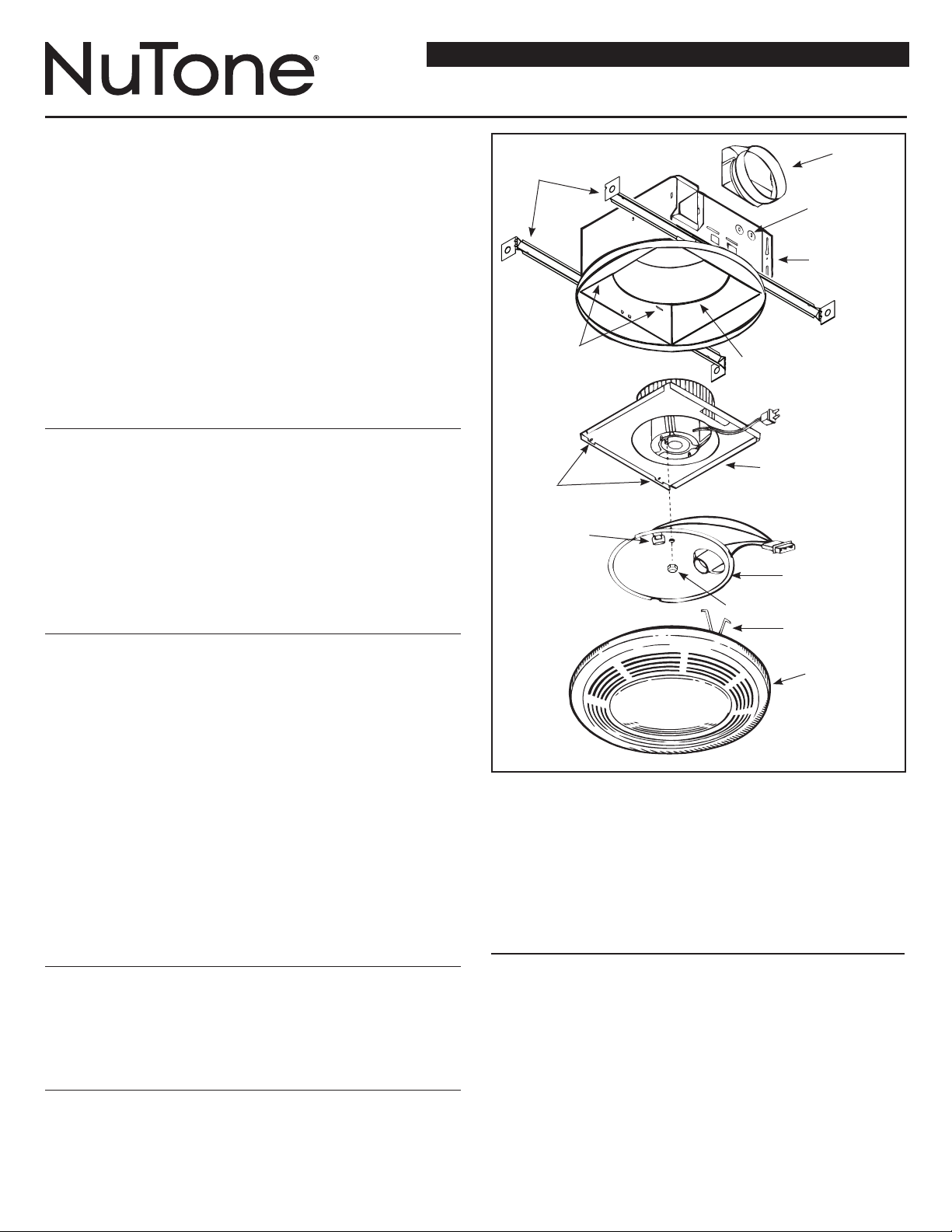
Duct
Hanger Bars
Collar
with Light
MODEL: 8663RP, 8664RP
Suitable for use in shower or tub enclosure when used
with GFI protected branch circuit.
Suitable for use in insulated ceilings.
WARNING: To reduce the risk of fire or electrical shock, do not use this
fan with any solid-state speed control device. Do not install in a ceiling
insulated to a value greater than R-40.
IMPORTANT SAFETY INSTRUCTIONS
WARNING – TO REDUCE THE RISK OF FIRE, ELECTRIC SHOCK, OR
INJURY TO PERSONS, OBSERVE THE FOLLOWING:
A. Use this unit only in the manner intended by the manufacturer.
If you have questions, contact the manufacturer.
B. Before servicing or cleaning unit, switch power off at Service Panel and
lock Service Panel to prevent power from being switched on accidentally.
When the service disconnecting means cannot be locked, securely fasten a prominent warning device, such as a tag, to the service panel.
CAUTION:
For general ventilating use only. Do not use to exhaust hazardous or
explosive materials and vapors.
INSTALLATION INSTRUCTIONS
WARNING – TO REDUCE THE RISK OF FIRE, ELECTRIC SHOCK, OR
INJURY TO PERSONS, OBSERVE THE FOLLOWING:
A. Installation work and electrical wiring must be done by qualified person(s)
in accordance with all applicable codes and standards, including fire-rated
construction.
B. Sufficient air is needed for proper combustion and exhausting of gases
through the flue (chimney) of fuel burning equipment to prevent back
drafting. Follow the heating equipment manufacturer’s guideline and
safety standards such as those published by the National Fire Protection
Association (NFPA),
and the American Society for Heating, Refrigeration and Air Conditioning
Engineers (ASHRAE), and the local code authorities.
C. When cutting or drilling into wall or ceiling, do not damage electrical wiring
and other hidden utilities.
D. Ducted fans must always be vented to the outdoors.
E. If this unit is to be installed over a tub or shower, it must be marked as
appropriate for the application.
F. NEVER place a switch where it can be reached from a tub or shower.
G.
For installation in sloped ceilings up to 12/12 pitch.
H.
Ductwork must point up.
FOR BEST RESULTS
When installing the Exhaust Fan/Light in a new construction site, install
housing during the rough-in construction of the building. The blower unit,
reflector and grille should be installed after the finished ceiling is in place.
Refer to instructions on page 3 to install the Exhaust Fan/Light in an exist-
ing finished building.
PLANNING DUCTWORK AND WIRING
1. Use 4” round duct.
2. Plan duct run from discharge opening of fan to the outside. For best fan
performance, make duct run as short as possible and use minimum number of elbows.
3. Use optional NuTone ducting accessories as needed.
Wiring
Knockouts
Housing
Slots
Tabs
Night Light
Socket
(not provided
on 8664RP)
Scroll
Power/Blower
Unit
Reflector
Assembly
Acorn Nut
Mounting
Springs (2)
Grille/Lens
Assembly
FIGURE 1
IMPORTANT: Use wire suitable for 90°C.
Plan to run 120vAC house wiring (with ground) from power source, through
wall switches, to junction box in fan. For separate control of fan, light, and
night light three wall switches are required. See NuTone Catalog for accessory switches. For separate control of fan, light, and night light, five conductors
are needed between the wall switch box and the fan’s junction box. (Night
light not provided on 8664RP).
INSTALLATION IN A NEW
CONSTRUCTION SITE
PREPARATION
1. Refer to Figure 1. Remove power unit/blower assembly from housing.
A. Unplug power unit.
B. Remove screw (located next to plug-in receptacle) which holds power/
blower unit mounting plate in place. Save screw.
C. Lift mounting plate at end near the plug-in receptacle until blower
wheel clears the scroll.
D. Remove plate by pulling its tabs out of slots in housing. Set power/
blower unit aside until needed.
2. Remove one of the wiring knockouts from housing.
Page 2
MOUNTING THE HOUSING
Note: When installing in existing construction, refer to page 3
Mounting Using Mounting Tabs
Refer to Figure 2.
1. Locate fan housing next to ceiling joist.
2. Use wood screws (not provided) to loosely attach housing to ceiling joist
through keyhole slots in mounting tabs.
3. Adjust housing so that it will be flush with finished ceiling. For the grille to fit
properly, the housing’s rim must not extend beyond finished ceiling surface.
4. When housing is properly adjusted, tighten screws in slots.
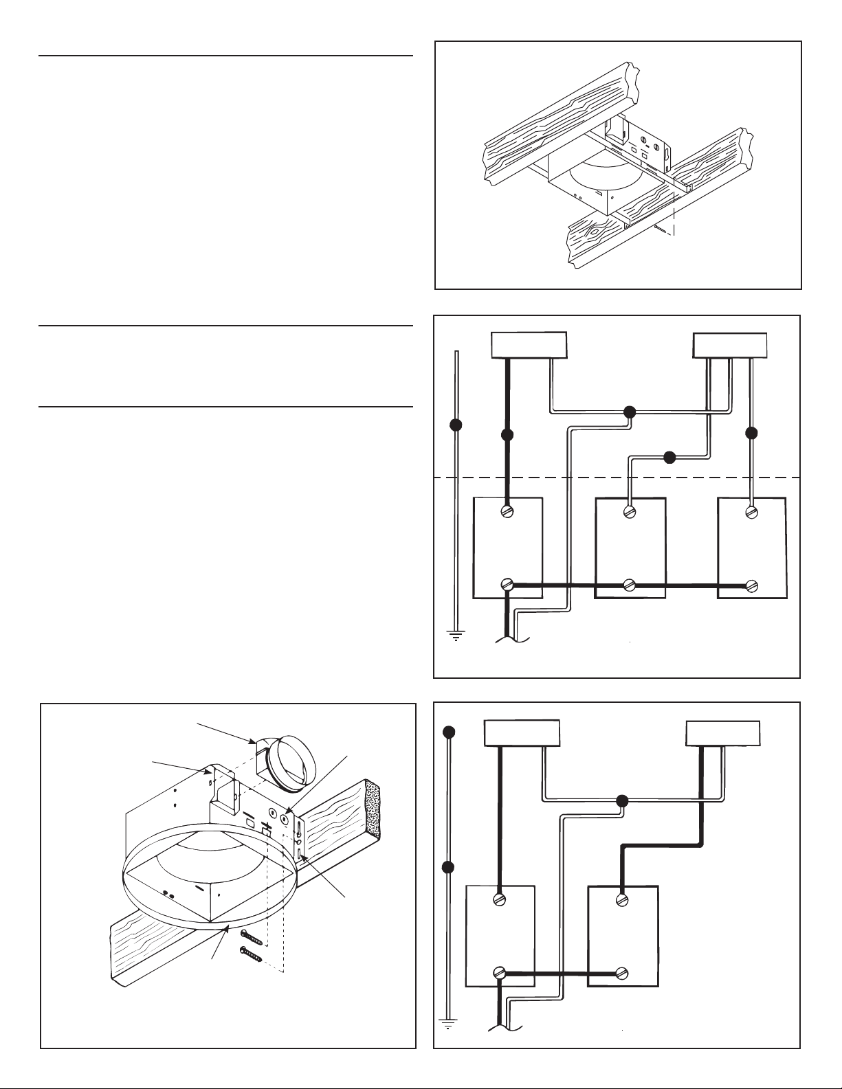
Mounting Using Hanger Bars
Refer to Figure 3.
1. Insert hanger bars in slots provded in housing.
2. Locate fan housing between joists so that the bottom of the housing is even
with the planned finished ceiling.
3. Use screws or nails (not provided) to secure hanger bars to ceiling joists.
INSTALLING DUCTWORK
1. Refer to Figure 1. Place duct collar over flanges at discharge opening of fan.
Secure collar by snapping tabs into slots in flanges.
2. Run 4” round duct from fan’s discharge opening to the outside and terminate.
WIRING
All wiring must comply with local codes and unit must be properly grounded.
IMPORTANT: Use wire suitable for 90°C.
1. Run 120vAC house wiring from wall switches to fan location, neutral (white),
ground (bare copper), and three switched hot leads. See Figure 4.
2. Insert and secure an approved box connector into wiring entrance hole.
3. Pull wires through box connector and into junction box. Tighten box connector.
4. Refer to Figure 4A. (For 8663RP)
Connect white wires from the fan and light receptacles to white (neutral) wire
from the supply. Connect black wire to wire from fan switch. Connect red wire
to wire from light switch. Connect yellow wire to wire from night light switch.
Refer to Figure 4B. (For 8664RP)
Connect white wires from the fan and light receptacles to white (neutral) wire
from the supply. Connect black wire from fan (BLK) receptacle to wire from fan
switch. Connect blue from light (WH) receptacles to wire from light switch.
5. Connect the green (or bare) ground wire to the green ground lead.
G
R
O
U
N
D
FAN
SWITCH
120 VAC
FAN
RECEPTACLE
B
L
K
WHITE
LIGHT
SWITCH
8663RP
FIGURE 3
LIGHT
RECEPTACLE
R
E
D
NIGHT
LIGHT
SWITCH
FIGURE 4A
Y
E
L
L
O
W
Duct Collar
Flanges
Bottom
Rim
Wiring
Knockouts
Mounting
Tabs
FIGURE 2
G
R
O
U
N
D
FAN
RECEPTACLE
B
L
K
FAN
SWITCH
120 VAC
WHITE
8664RP
LIGHT
SWITCH
LIGHT
RECEPTACLE
B
L
U
FIGURE 4B
Page 3

POWER/BLOWER UNIT INSTALLATION
1. Refer to Figure 1. Place power/blower unit into housing so that mounting
plate’s tabs insert into slots in housing.
2. Press other end of mounting plate down until it is firmly seated over scroll
and plug-in receptacles.
3. Secure mounting plate to housing with provided screw.
4. Insert motor plug into junction box receptacle.
COMPLETING INSTALLATION
11-1/2”
5-3/4”
1. Insert lamp plug into junction box receptacle and secure reflector assembly to
motor frame with wing nut provided.
2. Install lamps 100 watt (maximum) for light, and 7 watt (maximum) for
night light (Night light not provided on 8664RP).
3. Squeezing the grille assembly’s mounting springs together, insert springs into
slots on both sides of housing.
4. Press grille assembly firmly into place against ceiling.
INSTALLATION IN EXISTING CONSTRUCTION
Locate fan between ceiling joists.
Plan ducting wiring before proceeding with installation. Refer to Figure 4 for
wiring. CAUTION: Check area above planned location to be sure that:
1. Ducting can be installed.
2. Wiring can be run to the planned location.
3. No wiring or other obstruction might interfere with installation.
INSTALLATION FROM ACCESSIBLE AREA ABOVE
1. After determining desired location for fan, drill a small hole in the ceiling.
Place a coat hanger or other stiff wire up through hole to help in locating from
above.
2. Place fan housing on top of ceiling surface and use the housing as a
template to mark area to be cut out. Cut round hole 131⁄8” in diameter for
rough opening.
3. After cutting out opening, mount housing in the opening using the hanger
bars provided.
A. Insert hanger bars in slots in housing.
B. Position housing in opening so that bottom of housing is flush with ceiling.
C. Use screws or nails (not provided) to secure hanger bars to ceiling joists.
4. Install ducting and wiring as described above.
INSTALLATION FROM AREA BELOW CEILING
Note: If you do not have access to the area above the installation location, make
sure that the installation will not interfere with existing wiring, plumbing, etc. and
that the wiring and ducting can be run to the desired location. It will be necessary to use flexible duct when installing the unit from below.
1. The fan must be mounted between ceiling joists. Decide where you want to
locate the fan, and then determine where the nearest joists are.
Locating Joists – Lightly tap the ceiling. A hollow sound means no joist; a
solid sound means a joist is present. To be sure you have located a joist, drill
a small hole (1/16”) and probe into the ceiling with a wire.
2. Locate the joists. Drill a starter hole in the ceiling between the joists.
3. To exactly locate the edge of joist, saw a line from hole to joist.
4. Refer to page 1. Remove power/blower unit from housing.
5. Use the housing pan as a template to mark cutout: place pan centered
between joist and trace around pan.
6. Make cutout along outside of marked line.
7. Refer to Figure 5. Install 2 x 4 cleats to both ceiling joists. In some cases it
may be necessary to use more than a single cleat on one side. The distance
between cleats must be at least 91⁄8” but not more than 10”.
8. Remove side wiring knockout and insert and secure an approved box connector into the wiring entrance hole.
9. Use pliers to bend both mounting tabs as flush as possible to the side of the
housing.
10. Install duct collar.
11. String wiring through box connector and connect 4” flexible duct to duct col-
lar.
12. Carefully push ductwork and wiring back into cutout. Place housing into
cutout.
13. Use wood screws to secure housing to cleats through four holes in hous-
ing’s pan. Make sure pan is flush to finished ceiling.
14. Install Power/Blower Unit and complete installation.
2”
4”
9-1/8”-10”
Cleat
Joist
FIGURE 5
4” Flexible
Duct
120vAC
House Wiring
Duct
Mounting
Holes
Collar
Wiring
Knockout
Bend
Mounting
Tabs
Flush To
Side of
Housing
FIGURE 6
CLEANING AND RELAMPING
1. Pull grille assembly away from ceiling.
2. Squeezing the grille assembly’s mounting springs together, remove grille
assembly from housing to expose socket for relamping.
3. Clean grille and lens assembly using a mild soap and water solution.
Assemblies with wood frames should not be immersed.
4. Replace grille assembly flat against ceiling after cleaning or relamping.
Page 4

One Year Limited Warranty
WARRANTY OWNER: Broan-NuTone warrants to the original consumer purchaser of its products that such products will be free from defects in materials or workmanship for a period of
one (1) year from the date of original purchase. THERE ARE NO OTHER WARRANTIES, EXPRESS OR IMPLIED, INCLUDING, BUT NOT LIMITED TO, IMPLIED WARRANTIES OF
MERCHANTABILITY OR FITNESS FOR A PARTICULAR PURPOSE.
During this one year period, Broan-NuTone will, at its option, repair or replace, without charge, any product or part which is found to be defective under normal use and service. THIS
WARRANTY DOES NOT EXTEND TO FLUORESCENT LAMP STARTERS OR TUBES, FILTERS, DUCT, ROOF CAPS, WALL CAPS AND OTHER ACCESSORIES FOR DUCTING. This
warranty does not cover (a) normal maintenance and service or (b) any products or parts which have been subject to misuse, negligence, accident, improper maintenance or repair (other than
by Broan-NuTone), faulty installation or installation contrary to recommended installation instructions.
The duration of any implied warranty is limited to the one year period as specified for the express warranty. Some states do not allow limitation on how long an implied warranty lasts, so the
above limitation may not apply to you.
BROAN-NUTONE’S OBLIGATION TO REPAIR OR REPLACE, AT BROAN-NUTONE’S OPTION, SHALL BE THE PURCHASER’S SOLE AND EXCLUSIVE REMEDY UNDER THIS
WARRANTY. BROAN-NUTONE SHALL NOT BE LIABLE FOR INCIDENTAL, CONSEQUENTIAL OR SPECIAL DAMAGES ARISING OUT OF OR IN CONNECTION WITH PRODUCT
USE OR PERFORMANCE. Some states do not allow the exclusion or limitation of incidental or consequential damages, so the above limitation or exclusion may not apply to you. This warranty
gives you specific legal rights, and you may also have other rights, which vary from state to state. This warranty supersedes all prior warranties.
WARRANTY SERVICE: To qualify for warranty service, you must (a) notify Broan-NuTone at the address or telephone number below, (b) give the model number and part identification
and (c) describe the nature of any defect in the product or part. At the time of requesting warranty service, you must present evidence of the original purchase date.
Date of Installation
Builder or Installer
Model No. and Product Description
Broan-NuTone Canada Mississauga, Ontario www.nutone.ca 877-896-1119 Rev. 08/2007
Broan-NuTone LLC Hartford, Wisconsin www.nutone.com 888-336-3948
GARANTIE DU PROPRIÉTAIRE: Broan-NuTone garantie à l’acheteur original de ses produits que ces derniers seront exmpts de tout défaut de matériaux et de fabrication pour une
période d’un (1) an à compter de la date d’acha. AUCUNE AUTRE GARANTIE, IMPLICITE OU EXPRESSE, N’EST DONNÉE, Y COMPRIS, MAIS SANS S’Y LIMITER, GARANTIE DE
MARCHANDIBILITÉ OU D’ADAPTATION À UN USAGE PARTICULIER.
Pendant cette période d’un an, Broan-NuTone procédera au remplacement ou à la réparation sans aucuns frais, mais à sa propre discrétion, de tout produit ou pièce jugé défectueux dans
le cadre d’une utilisation normale. CETTE GARANATIE NE VISE PAS LES DISPOSITIFS D’AMORCAGE NI LES TUBES DES LUMINAIRES FLUORESCENTS. Cette garantie ne couvre pas
(a) l’entretien et le service courants ni (b) les produits et les pièces ayant fait l’objet du’n usage abusif, de négligence, d’un accident, d’un entretien ou d’une réparation non appropriée (par du
personnel non autorisé par Broan-NuTone) d’une mauvaise installation ou d’une installation non conforme aux directives d’installation fournies.
La durée de toute garantie implicite est limitée à la période de deux ans précisée pour la garantie expresse. Certains états ne reconnaissent pas les restrictions relatives à la durée des garanties
implicites; il se pourrait donc que cette restriction ne s’applique pas dans votre cas.
LE REMPLACEMENT OU LA RÉPARATION PAR BROAN-NUTONE, À SA PROPRE DISCRÉTION, DE TOUT PRODUIT OU PIÈCE DÉFECTUEUX CONSTITUE LE SEUL REMÈDE
DE L’ACHETEUR EN VERTU DE CETTE GARANTIE. BROAN-NUTONE NE PEUT ÊTRE TENUE RESPONSABLE DES DOMMAGES INDIRECTS, CONSÉCUTIFS OU SPÉCIAUX
ATTRIBUABLES À UTILISATION OU AU RENDEMENT DU PRODUIT. Certains états ne reconnaissent pas les restrictions ni les exclusions relatives aux dommages indirects, consécutifs ou
spéciaux; il se pourrait donc que cette restriction ne s’applique pas dans votre cas. La présente garantie vous accorde des droits spécifiques, mais vous pourriez aussi avoir d’autres droits en
fonction de l’état dans lequel vous résidez. Cette garantie remplace toute autre garantie donnée précédement.
SERVICE SOUS GRANTIE: Pour être admissible au service sous garantie, vous devez (a) aviser Broan-NuTone, à l’adresse ou au numéro de téléphone ci-dessous, (b) fournir le
numéro du modèle et la description de la pièce et (c) décrire la nature défaut de la pièce ou du produit. Au moment de la demande de service sous garantie, vous devez fournir
une preuve de la date d’achat originale.
Date d’installation
Entrepeneur ou installateur
N° de modèle et description du produit
Broan-NuTone LLC Hartford, Wisconsin www.nutone.com 888-336-3948
Broan-NuTone Canada Mississauga, Ontario www.nutone.ca 877-896-1119 Rev. 08/2007
IF YOU NEED ASSISTANCE OR SERVICE - CONTACT:
Garantie limitée d’un an
POUR OBTENIR DE L’ASSITANCE OU DU SERVICE - CONTACTEZ:
Garantia Limitada de un Año
GARANTÍA DEL PROPIETARIO: Broan-NuTone garantiza al comprador consumidor original de sus productos, por el período de un (1) año desde la fecha original de compra, que tales productos están libres de defectos en material y mano de obra. NO HAY OTRAS GRANTÍAS, EXPRESADOS O SOBREENTENDIDAS, INCLUYENDO, PERO NO LIMITADAS A, GRANTÍAS
NO EXPRESADAS DE MERCHNTIBILIDAD O ADAPTABLES A UN PROPÓSITO EN PARTICULAR.
Durante este período de un año, Broan-NuTone reparará o reemplazará a su opción y sin costo, cualquier producto o parte que se encuentre defectuoso bajo condiciones normales de uso y servicio. ESTA GARANTÍA NO CUBRE A LOS ARRANCADORES PARA LÁMPARAS FLUORESCENTES O A LOS TUBOS FLUORESCENTES, FILTROS, DUCTOS, TAPAS DE TECHO, TAPAS
DE PARED Y OTROS ACCESORIOS PARA CANALIZACIÓN. Esta granatía no cubre (a) Mantenimiento y servicios normales (b) Productos o partes sujetos al mal uso, negligencia, accidente,
mantenimiento inadecuado o reparaciones (port otros ajenos a Broan-NuTone), instalación defectusoa o a una instalación contraria a las instrucciones de instalación recomendadas.
La duración de cualquier garantia no expresada está limitada a un periodo de un año según se especifica en la garantia expresada. Algunos estados no permiten limitación en cuanto a la duración
de una grantia no expresada, por lo que la limitación arriba indicada puede que no se apliqué a Ud.
LA OBLIGACIÓN DE BROAN-NUTONE DE REPARAR O REEMPLAZAR A SU OPCIÓN, SERÁ EL ÚNICO Y EXCLUSIVO RECURSO QUE TENDRÁ EL COMPRADOR BAJO
ESTA GARANTÍA. BROAN-NUTONE NO SERÁ RESPONSABLE POR DAÑOS INCIDENTALES, CONSECUENTES O ESPECIALES QUE RESULTEN A CONSECUENCIA O SEAN
INDEPENDIENTE DEL USO O DESEMPEÑO DEL PRODUCTO. Algunos estados no permiten la exclusión o limitación de daños incidentals o consecuentes, de modo que la limitación o
exclusión arriba indicada pueda que no se aplique a Ud. Esta garantia le proporciona derechos legales especificos, y Ud.puede tener otros derechos, los cuales varían de estado a estado. Esta
garantias reemplaza a todas las garantías anteriores..
SERVICO DE GARANTÍA: Para tener derecho al servicio de garantía, Ud. debe (a) Notificar a Broan-NuTone a la dirección o el número de teléfono abajo, (b) indicar el número de
modelo y la identifación de la party y (c) describir la naturaleza de cualquier defecto en la producto o parte. Al momento de solicitor el servicio por la garantía, Ud. debe presentar
la evidencia de la fecha original de compra.
Fecha de la instalación
Constructor o instalador
Número de modelo y descripción del producto
Broan-NuTone Canada Mississauga, Ontario www.nutone.ca 877-896-1119 Rev. 08/2007
Broan-NuTone LLC Hartford, Wisconsin www.nutone.com 888-336-3948
SI NECESITA ASISTENCIA O SERIVIVIO - CONTACTO:
Page 5

12
14
11
12
13
9
17
6
7
15
16
8663RP
PARTS SHOWN
4
5
1
3
10
8
2
SERVICE PARTS
ModelS 8663RP & 8664RP
KEY NO. PART NUMBER DESCRIPTION
1 97017705 Power Unit Assembly (8663RP)
1 97017706 Power Unit Assembly (8664RP)
2 100599000 Motor
3 32787000 Motor Isolation Mount
4 32788000 Ground Clip
5 100603000 Blower Wheel
6 85974000 ReectorAssembly(8663RP)
6 86000000 ReectorAssembly(8664RP)
7 85950000 Lamp Socket Assembly (8663RP)
7 85979000 Lamp Socket (8664RP)
8 30652000 Duct Adapter Assembly
9 44388000 Hanger Bar (1)
10 97017702 Grille Assembly
11 99111406 Grille
12 61753000 Lens
13 0444A000 Grille Spring Set
14 99260575 Acorn Nut
15 99270982 Fan Receptacle
16 36892000 Light Receptacle (8663RP)
16 99270981 Light Receptacle (8664RP)
17 101049000 Reector
Broan-NuTone LLC Hartford, Wisconsin www.nutone.com 888-336-3948
Page 6

99044123B
 Loading...