

Page 1
1. For b athroom applic ations the Control s hould be placed at a l evel to detect
humidity. Placi ng the Control dire ctly above a heater or ne ar drafts is not
recommended.
2. It is rec ommended that in la rge spaces the Broa n-NuTone Premium Humidit y
Sensing Wall Con trol be placed with in close proximit y to the shower/tub/
sink (main sourc e of the humidity/ste am) to most effective ly measure/detect
excess humidity.
INSTALLATION
1. Turn power (circuit breaker) OFF.
2. Remove existing switch c over and switch from wal l box.
3. Disconnect and label switch wires.
4. Connect Black (HOT ), White (Neutral - R equired) and Bl ack or Red (Load)
wires to Humidity Wall Control Switch.
5. Install Humidity Co ntrol in wall box, and s ecure with the two at tached screws.
6. Install wall plate (not provided ) on Humidity Control, a nd secure with the two
captive screws.
7. Turn power (circuit breaker) ON. No te: When power is applie d, the Model 82W
requires appr ox. 30 seconds to bo ot up and be ready to func tion.
8. Remove lower switch cover an d adjust initial co ntrol mode potent iometers.
LOWER COVER REM OVAL AND INSTALL
Installation Instructions
INCLUDED
Switch
Instruction Sheet
Note: Wall plate no t included – Use Broan Pa rt No. S97012925 (or equ ivalent)
CONTROL SPECIFICATIONS
• cULus listed
• 120 VAC 60 Hz Line Power
• 9A Max. Total Load (Fan + Lam p)
• When used in com bination with fan /light fixture s that are switched to gether,
the device is rat ed for the following l amps: 600W Incand escent, 150W
LED, 150W CFL, or 400VA Induc tive Ballasted Flu orescent Lamps
• Typical wire sizes: 12AWG (MA X) or 14AWG solid or strand ed copper wire
• Operating temperature: 0-50°C (32-122°F)
SAFETY
Before installi ng control, swi tch power off at ser vice panel and lock the serv ice
disconnecting means to prevent power from being switched on accidentally. When
the service disconnecting means cannot be locked, securely fasten a prominent
warning devic e, such as a tag, to the se rvice panel.
Installatio n work and electr ical wiring mu st be done by a quali fied person(s) in
accordance with all applicable codes and standards.
1. Us e copper wire only.
2. CAUTION: R isk of Electric Shock - M ore than one disconne ct switch may be
required to de-energize the equipment before servicing.
3. WARNING: T his device shall not be used in c ombination with a wall switc h
controlling a receptacle.
4. Insta ll only in a UL Listed jun ction box sized 50. 8 x 76.2 x 76.2 mm (2.0 x 3.0 x
3.0 in.) or larger, minim um volume 295 CM3 (18.0 in3).
5. Requi res a neutral wire for o peration.
6. Note: Whe n power is applied, th e Model 82W requires a pprox. 30 second s to
boot up and be read y to function.
A
Removal:
• Grasp s ides of lower cover and
pull straight outward.
B
Install:
• Align t abs on cover with hol es
in metal panel an d push
straight inward
B
A
A
Démontage :
• Agrip pez les côtés du capo t
inférieur et tir ez en ligne droite.
B
Installation :
• Align ez les ergots du capo t
sur les trous du pa nneau
métallique et p oussez vers
l’intérieur.
B
A
B
A
A
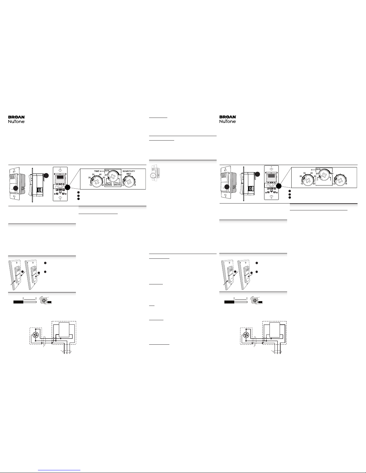
ON/OFF Switc h and LED (Fan ON/OFF I ndicator)
Ground Wire
Potentiometer Adjustable Dial Settings - Remove lower cover on control face
B
C
C
(Factory default settings shown.)
Model 82W
Premium Humidity Sensing Wall
Control
WIRE INSTALLATION & WIRING DIAGRAM
INSTALLATION DE S FILS ET SCHÉMA D E CÂBLAGE
CONTROL MODE SETTINGS (POTENTIOMETER ADJUSTMENTS)
AUTO SENSE / RH % / CYCLE Potentiomete r:
• AUTO SENSE Mode:
The c ontrol has an auto matic sensing m ode (AUTO SENSE) that senses
increasing changes in humidity level (i.e. Sense on Rise). Once the threshold
is met, the bath fa n will activate withi n 2 minutes with the d evice located wit hin
8 feet from the humi dity source (e.g. shower head or f aucet). Fan activation
may take longer if t he Control is located fu rther than 8 feet from th e humidity
source. The fan wi ll remain ON based on the use r adjustable TIME function
(See TIME Potentiometer description).
TIME: User adjustab le from 10-60 minu tes per hour, in 10 minute incr ements
AUTO S ENSE / RH% / CYCLE : AUTO SENSE
SENSITIVITY: Active; user adjust able from LO to HI
Control Function:
SEN SE ON RISE is ACTIVE
SENSITIVIT Y is ACTIVE
• CYCLE (Air Cycling) Mode:
The control provides a pre-set ventilation ON TIME for meeting continuous
ventilation codes. After the initial ON time is set by manually turning the fan ON,
the control will provide continuous activation cycles every hour. Also, Sense on
Rise is active in the CYCLE mode, so if the control is in the “Fan OFF” portion
of the cycle and it senses a rise in humidity it will bypass the remainder of the
OFF cycle and start a new ON cycle with a time duration equal to the TIME
potentiometer setting.
To calculate the applicable TIME potentiometer setting, use the following formula:
TIME potentiometer setting = (required CFM1 ÷ fan CFM) x 60
1 from ASHRAE 62.2 formula/table (based on square footage and number of
bedrooms)
TIME: User adjustab le from 10-60 minu tes per hour, in 10 minute incr ements
AUTO S ENSE / RH% / CYCLE : CYCLE
SENSITIVITY: Active; user adjust able from LO to HI
Control Function:
SEN SE ON RISE is ACTIVE
SENSITIVIT Y is ACTIVE
• RH% (Humidistat) M ode:
The control has a RH% mo de with a user adju stable thres hold relative
humidity leve l. The RH% setting can be adj usted from 20 to 80% RH in 10%
RH increment s. Once the threshold i s met, or if SENSE ON RISE detec ts an
increase in hum idity, the connected fa n should activate with in 2 minutes with
the device loc ated within 8 feet from t he humidity sourc e (e.g. shower head or
faucet). Fan activat ion may take longer if the Contr ol is located further than
8 feet from the humi dity source. The fan will rem ain ON based on the user
adjustable TIME function.
TIME: User adjustab le from 10-60 minu tes per hour, in 10 minute incr ements
AU TO SENSE / RH % / CYCLE: RH%; user ad justable from 2 0-80% in 10% RH
increments.
SENSITIVITY: Inactive
Control Function:
SEN SE ON RISE is ACTIVE
SENSITIVIT Y is INACTIVE.
When room humidity reaches RH% potentiometer setting:
- Fan (and LED) will turn ON.
- When timer time s out, Fan (and LED) will turn OFF until a nother event
occurs, or is st ill occurring (i.e. amb ient humidity is stil l at or above RH%
setpoint, amb ient humidity reach es the RH% setpoint again o r Sense on
Rise detects a r ise in humidity lev el).
TIME Potentiometer:
The TIME potenti ometer is used to s et the fan run time eve ry time the fan
turns ON. It can be a djusted to run between 10 and 60 mi nutes, in 10 minute
increments. I n CYCLE mode the TIME select ion is the portion of ea ch hour that
the fan will run, a nd the countdown begins w hen CYCLE mode is selected and
the fan turns ON. I n MANUAL mode the TIME co untdown begins whe n the fan is
turned ON usin g the ON/OFF switc h. In AUTO SENSE and RH% mo des the TIME
countdown begins when the relative humidity stops rising.
SENSITIVITY Potentiometer:
The SENSITIVIT Y potentiometer is us ed to adjust the contr ols’ sensitivit y to ambient humidif ied air and to the size of the room . In a low humidity environm ent
and/or large ro om, it may be necess ary to adjust the SE NSITIVITY potent iometer
to a higher sett ing (MED to HI) to increase the contr ol sensitivity for humidi ty
detection. In a h igh humidity e nvironment and /or small room, it m ay be necessar y
to adjust the SENS ITIVITY potent iometer to a lower se tting (LO to MED) to red uce
the control sensitivity for humidity detection and to prevent undesired activations.
MANUAL OPERATION MODE
Note: Regardless o f all other setti ngs, the front panel b lue LED
will always be ON when fan i s ON, and OFF when fan is OFF.
The control ha s a manual operation mode w ith the ability to turn th e fan ON or
OFF at the user’s dis cretion. Press and rele ase the lower control swit ch to turn
the fan ON or OFF.
In addition to ma nually turning the fan OFF, the manu al mode also utilizes the
automatic OFF function with user adjustable fan ON time duration, as described
previously in the TIME Potentiometer section. With this feature the user can manually turn the fa n ON and not be concerne d about manually tur ning the fan back
OFF, because the TIME fu nction will turn t he fan OFF automatica lly.
The manual mod e will override the AUTO SEN SE / RH% / CYCLE modes whenever they are active. T his mode sett ing will turn OFF al l user adjusta ble set points,
with the excepti on of the TIME setting, until the s witch is manually turne d OFF
or the switch tur ns OFF automaticall y due to the TIME countdow n, at which time
the unit will ret urn to the previous mo des setting(s) follow ing a 5-minute del ay.
In other words, if t he fan is turned O N manually, and then t urned OFF manua lly (or
due to the TIME cou ntdown completin g its cycle), and if the previ ous setting was
RH%, then follo wing a 5-minute delay t he control will return to t he RH% setting
and turn the fan ON i f the RH set point is reached, sur passed, or if the Contro l
senses the app ropriate rate of rise o f humidity.
If the previous se tting was AUTO, the c ontrol will turn t he fan ON (after the 5- minute delay) if the con trol senses the app ropriate rate of ris e of humidity.
TIME: User adjustab le from 10-60 minu tes per hour, in 10 minute incr ements
AUTO SENSE / RH % / CYCLE: Inactive
SENSITIVITY: Inactive
Control Function:
Regardless o f the MODE the unit is in, pr essing the front pane l switch overrides
that mode to imme diately turn the Fan ON i f it was OFF, or OFF if it was ON.
Limited Warranty
Warranty Period an d Exclusions: Broa n-NuTone LLC (the “Company ”) warrants to the or iginal consum er purchaser
of its product (“yo u”) that the pro duct (the “Prod uct”) will b e free from materia l defects in the Pr oduct or its wor kmanship
for a period of one (1) year from the d ate of original purc hase.
The limited warrant y period for any replaceme nt parts provided by the Co mpany and for any Products rep aired or
replaced under th is limited warrant y shall be the rema inder of the orig inal warranty per iod.
This warranty doe s not cover repellent car tridges or repell ent cartridge refi lls that may be purchase d separately and
installed with the P roduct. This warrant y also does not cover (a) normal ma intenance and servi ce, (b) normal wear
and tear, (c) any Products or par ts which have been su bject to misuse, ab use, abnormal usag e, negligence, ac cident,
improper or insuf ficient maintenance, s torage or repair (other than re pair by the Company), (d) damage cau sed by
faulty installat ion, or install ation or use cont rary to recom mendations o r instructio ns, (e) damage cause d by exposure to
salt air (f) damage in tr ansit, (g) natural wear of f inish, (h) Products in c ommercial or non residential use, o r (i) damage
caused by fire, flood o r other act of God. This wa rranty covers only Pr oducts sold to ori ginal consumers in t he United
States by the Company or U. S. distributor s authorized by the Co mpany.
This warranty supersedes all prior warranties and is not transferable from the original consumer purchaser.
No Other Warranties: This Limited Warranty contai ns the Company’s sole obligati on and your sole remedy for
defective produc ts. The foregoing warrant ies are exclusive and in lieu of any o ther warranties, express o r implied.
THE COMPANY DISCLAIMS AND EXCLUDES ALL OTHER EXPRESS WARRANTIES, AND DISCLAIMS
AND EXCLUDES ALL WARR ANTIES IMPLIED BY LAW, INCLUDING W ITHOUT LIMITATION THOSE OF
MERCHANTABILIT Y AND FITNESS FOR A PAR TICULAR PURPOSE . To the extent that applica ble law prohibits
the exclusion of impl ied warranties, t he duration of any ap plicable imp lied warranty is li mited to the perio d specified for
the express warrant y above. Some states d o not allow limitati ons on how long an imp lied warranty las ts, so the above
limitation may not ap ply to you. Any oral or wr itten descri ption of the Produ ct is for the sole pur pose of identif ying it and
shall not be constru ed as an express warr anty.
Whenever possible , each provision of th is Limited Warrant y shall be interpre ted in such manner a s to be effective and
valid under applic able law, but if any prov ision is held to be p rohibited or inva lid, such provis ion shall be inef fective only
to the extent of such pro hibition or inva lidity, without i nvalidating th e remainder of suc h provision or th e other remainin g
provisions of the Limited Warranty.
Remedy: During the applicabl e limited warrant y period, the Com pany will, at its opti on, provide repla cement parts for,
or repair or replace, w ithout charg e, any Product or par t thereof, to the ex tent the Compa ny finds it to be cove red by and
in breach of this limi ted warranty un der normal us e and servic e. The Company wi ll ship the rep aired or replac ed Product
or replacement par ts to you at no charge. You are respo nsible for all costs for re moval, reinstallation a nd shipping,
insurance or other fr eight charges incur red in the shipment of th e Product or part to the C ompany. If you must send
the Product or part t o the Company, as instruc ted by the Company, you must pr operly pack the Prod uct or part—the
Company is not respo nsible for dam age in transit. T he Company res erves the rig ht to utilize reco nditioned, r efurbished ,
repaired or remanuf actured Produc ts or parts in the war ranty repair or re placement proc ess. Such Produ cts and parts
will be comparabl e in function and per formance to an origi nal Product or part an d warranted for the rema inder of the
original warranty period.
Exclusion of Damag es: THE COMPANY’S O BLIGATION TO PROV IDE REPLACE MENT PARTS, OR R EPAIR OR
REPLACE, AT THE COMPAN Y’S OPTION, SHAL L BE YOUR SOLE AND EXCLUSI VE REMEDY UNDER THIS
LIMITED WARRAN TY AND THE COMPANY’S S OLE AND EXCLUSIVE OB LIGATION. THE COMPAN Y SHALL
NOT BE LIABLE FOR IN CIDENTAL, INDI RECT, CONSEQUEN TIAL OR SPECIAL DAM AGES ARISING OU T OF
OR IN CONNECTIO N WITH THE PROD UCT, ITS USE OR PERFO RMANCE.
Some states do not all ow the exclusion or limit ation of incidental or c onsequential dam ages, so the above limitat ion
or exclusion may not app ly to you. This warranty g ives you specific leg al rights, and you may als o have other rights,
which vary from sta te to state.
This warranty cover s only replacement o r repair of defective Pr oducts or parts th ereof at the Company’s m ain facility
and does not includ e the cost of field s ervice travel an d living expenses .
Any assistance th e Company provides t o or procures for you ou tside the terms, l imitations or excl usions of this lim ited
warranty will not co nstitute a waiver of suc h terms, limitatio ns or exclusions, nor w ill such assista nce extend or revive
the warranty.
The Company will not re imburse you for any ex penses incurre d by you in repairing or r eplacing any defe ctive Product,
except for those incu rred with the Comp any’s prior writt en permission.
How to Obtain Warrant y Service: To qualif y for warranty ser vice, you must (a) notif y the Company at the ad dress or
telephone number s tated below wit hin seven (7) days of di scovering the c overed defect, (b) g ive the model num ber and
part identific ation and (c) describe the n ature of any defect in the Pro duct or part. At the tim e of requesting warran ty
service, you must pr esent evidence of the o riginal purchase d ate. If you cannot provid e a copy of the original wr itten
limited warranty, the n the terms of the Comp any’s most current wri tten limited warra nty for your partic ular product will
control. The most cu rrent limited wri tten warrantie s for the Company’s pr oducts can be fou nd at www.broan.c om .
Broan-NuTone LLC 926 West State St reet, Hartfor d, WI 53027 www.b roan.com 800 -637-1453
1. Pour les applications de salles de bain, la commande doit être installée à un certain
niveau pour détecter l’humidité. Il n’est pas recommandé d’installer la commande
directement au-dessus d’un appareil de chauffage ou près d’un tirage.
2. Dans les grands espaces, il est recommandé d’installer la super commande
murale de détection d’humidité Broan-NuTone à proximité de la douche/de la
baignoire/de l’évier (principale source d’humidité/de vapeur) afin de mesurer/
détecter l’humidité de la manière la plus efficace possible.
INSTALLATION
1. Coupez l’alimentation (disjoncteur).
2. Déposez le couvercle de l’interrupteur et l’interrupteur de la boîte murale.
3. Déconnectez et étiquetez les fils de l’interrupteur.
4. Connectez les fils noir (CHAUD), blanc (NEUTRE - requis) et noir ou rouge
(CHARGE) à l’interrupteur de la commande murale de détection d’humidité.
5. Installez la commande de détection d’humidité dans la boîte murale et fixez-les à
l’aide des deux vis fournies.
6. Installez la plaque murale (non fournie) sur la commande de détection d’humidité
et fixez-les à l’aide des deux vis imperdables.
7. Rétablissez le courant (au disjoncteur). Remarque : Lorsque le courant est
rétabli, le Modèle 82W prend environ 30 secondes pour se réinitialiser et être prêt à
fonctionner.
8. Retirez le couvercle inférieur de l’interrupteur et effectuez les premiers réglages
du mode de contrôle du potentiomètre.
RETRAIT ET INSTALLATION DU COUVERCLE INFÉRIEUR
Instructions d’installation
INCLUS
Interrupteur
Fiche d’instructions
Remarque: Plaque murale non incluse, utilisez la pièce Broan N°S97012925
(ou l’équivalent)
SPÉCIFICATIONS DE LA COMMANDE
• Homologuée cULus
• Puissance de ligne 120 VCA 60 Hz
• 9A cax. charge totale (ventilateur + ampoule)
•
Lorsqu’il est utilisé conjointement avec un ventilateur/des luminaires branchés
ensemble,
cet appareil est conçu pour les lampes suivantes: une ampoule
à incandescence de 600 W, DEL de 150 W, CFL de 150 W, des lampes
fluorescentes à ballast inductif de 400 VA
• Calibre type des fils : fil de cuivre massif ou tressé 12AWG (max.) ou 14AWG
• Température de fonctionnement: 0-50°C (32-122°F)
SÉCURITÉ
Avant d’installer la commande, coupez l’alimentation électrique sur le panneau
de service et verrouillez les dispositifs de sectionnement pour empêcher la
remise sous tension accidentelle. Lorsque vous ne pouvez pas verrouiller les
dispositifs de sectionnement, serrez à fond un dispositif d’avertissement bien
visible, comme une étiquette sur le panneau de service.
Les travaux d’installation et le câblage électrique doivent être effectués par
une personne qualifiée conformément aux codes et normes applicables.
1. Utilisez uniquement du fil de cuivre.
2. MISE EN GARDE: risque de choc électrique. Il peut s’avérer nécessaire d’utiliser
plus d’un sectionneur pour mettre l’équipement hors tension avant d’effectuer les
travaux d’entretien.
3. AVERTISSEMENT: cet appareil ne doit pas être utilisé en association avec un
interrupteur mural qui contrôle une prise.
4. Installez uniquement une boîte de jonction homologuée UL aux dimensions
suivantes 50,8 x 76,2 x 76,2 mm (2,0 x 3,0 x 3,0 po.) ou supérieures et d’un
volume minimum de 295 CM3 (18,0 po3).
5. Nécessite un câble neutre pour l’opération.
6. Remarque : Lorsque le courant est rétabli, le Modèle 82W prend environ
30secondes pour se réinitialiser et être prêt à fonctionner.
B
A
A
Interrupteur MARCHE/ARRÊT et DEL (voyant MARCHE/ARRÊT du ventilateur)
Conducteur de terre
Paramètres réglables du cadran du potentiomètre – retirez le couvercle inférieur
sur la face de la commande
B
C
C
(Réglages par défaut en usine affichés.)
Modèle 82W
Super commande murale de
détection d’humidité
RÉGLAGES DU MODE DE CONTRÔLE (RÉGLAGES DU POTENTIOMÈTRE)
POTENTIOMÈTRE DE DÉTECTION AUTOMATIQUE/RH%/DE CYCLE:
• Mode DÉTECTION AUTOMATIQUE:
La commande dispose d’un mode de détection automatique (DÉTECTION
AUTOMATIQUE) qui détecte les changements croissants du niveau d’humidité
(c-à-d. détection en cas d’augmentation). Une fois le seuil atteint, le ventilateur
de bain s’active dans un délai de 2 minutes, si la commande est située à 8
pieds de la source d’humidité (p.ex. pomme ou robinet de douche) L’activation
du ventilateur peut durer plus longtemps si la commande est située à plus de
8 pieds de la source d’humidité. Le ventilateur reste ALLUMÉ en fonction de la
TEMPORISATION réglée par l’utilisateur (voir description du potentiomètre de
TEMPORISATION).
TEMPORISATION : Réglable entre 10 et 60 minutes par heure, par incréments de
10 minutes
DÉTECTION AUTOMATIQUE/ RH%/CYCLE : DÉTECTION AUTOMATIQUE
SENSIBILITÉ: Activée; réglable entre les paramètres BAS et HAUT
Fonction de la commande :
DÉTECTION EN CAS D’AUGMENTATION EST ACTIVÉE
SENSIBILITÉEST ACTIVÉE
• Mode CYCLE (circulation de l’air) :
Pour répondre aux codes de ventilation continue, la commande fournit une
DURÉE de fonctionnement préréglée de la ventilation. Après le réglage initial de
la durée de fonctionnement qui s’effectue manuellement en mettant le ventilateur
en marche, la commande fournit des cycles d’activation continus toutes les
heures. En outre, la détection en cas d’augmentation est activée en mode CYCLE;
par conséquent, si la commande se trouve dans la partie « VENTILATEUR À
L’ARRÊT » du cycle et elle détecte une augmentation de l’humidité, la commande
va ignorer le restant du cycle ARRÊT et démarrer un nouveau cycle MARCHE
avec une durée égale au réglage du potentiomètre de temporisation.
Pour calculer la DURÉE applicable du potentiomètre de temporisation, utilisez
la formule suivante : DURÉE réglée sur le potentiomètre = (PCM1 requis ÷ PCM
ventilateur) x 60
1 D’après la formule/table 62.2 de l’ASHRAE (selon la superficie en pieds carrés
et le nombre de chambres)
TEMPORISATION : Réglable entre 10 et 60 minutes par heure, par incréments
de 10 minutes
DÉTECTION AUTOMATIQUE/ RH%/CYCLE : CYCLE
SENSIBILITÉ: Activée; réglable entre les paramètres BAS et HAUT
Fonction de la commande :
DÉTECTION EN CAS D’AUGMENTATION EST ACTIVÉE
SENSIBILITÉEST ACTIVÉE
• Mode RH% (humidostat) :
La commande dispose d’un mode RH% et d’un seuil réglable du niveau
d’humidité relative. Il est possible de régler le paramètre RH% entre 20 et
80% RH en incréments de 10 % d’humidité relative. Une fois le seuil atteint
ou si la DÉTECTION EN CAS D’AUGMENTATION détecte une augmentation
de l’humidité, le ventilateur raccordé s’active dans un délai de 2 minutes si la
commande est située à 8 pieds de la source d’humidité (p. ex. pomme ou robinet
de douche). L’activation du ventilateur peut durer plus longtemps si la commande
est située à plus de 8 pieds de la source d’humidité. Le ventilateur reste allumé
en fonction de la TEMPORISATION réglée par l’utilisateur.
TEMPORISATION : Réglable entre 10 et 60 minutes par heure, par incréments
de 10 minutes
DÉTECTION AUTOMATIQUE/ RH%/CYCLE : RH% ; réglable entre 20-80 % en
incréments de 10 % d’humidité relative.
SENSIBILITÉ: Désactivée
Fonction de la commande :
DÉTECTION EN CAS D’AUGMENTATION EST ACTIVÉE
La SENSIBILITÉ est DÉSACTIVÉE.
Lorsque l’humidité ambiante atteint le paramètre RH% du potentiomètre:
- Le ventilateur (et le voyant DEL) sont allumés
- Lorsque le temporisateur expire, le ventilateur (et le voyant DEL)
s’éteignent jusqu’à la prochaine occurrence (c.à.d. si l’humidité ambiante
est toujours égale ou supérieure au point de consigne RH%, l’humidité
ambiante atteint à nouveau le point de consigne RH% ou si Détection en
cas d’augmentation capte une élévation du niveau d’humidité)
HEURE
DÉTECTION
AUTOMATIQUE
CYCLE
(MIN/HR)
SENSIBILITÉ
MOY
Wire terminals a ccept up to #12 AWG MAX solid a nd stranded wire.
1. Remove combination Screw/Washer from terminal.
2. Wrap stri pped end of Wire arou nd Screw thread - und er Washer.
3. Re-install Screw/Washer - making sure Wire remains under Washer. Tighten
terminal screw s to 1.8 - 2.2 N-m (15.9 - 19.5 in.lb.).
4. Note: Scr ew/Washer
are not designe d for
straight inse rtion of
stripped wire . Use
only wire forme d
into a “J” loop and
wrapped around
Screw thread for
proper mechanical
and electric al
connection.
Les bornes de co nnexion accepte nt des fils de cuivre m assif ou tressé d’un
calibre de 12 AWG au maxi mum.
1. Enlevez l’en semble de vis et ron delle de la borne.
2. Enroul ez le fil dénudé autour d e la vis, sous la rond elle.
3. Repos ez l’ensemble de vis et r ondelle, en vous ass urant que le fil reste
bien sous la rondelle. Serrez les vis des
bornes à un coup le de 1,8 à 2,2 N-m
(15,9à19,5po-lb).
4. Remarq ue : Les
ensembles de
vis et rondell e ne
sont pas conçu s
pour insérer le f il
dénudé en ligne
droite. N’utilisez
que des fils don t
l’extrémité en
forme de « J » est
placée sur les fi lets
des vis pour de
bonnes connexions
mécaniques et
électriques.
Wire
3/4” (1.9 cm)
Washer
Screw
Wire under Washer
& Screw Head
Cable
3/4 po. (1.9cm)
Rondelle
Vis
Fil sous la rondelle
et la tête de vis
NOIR
BLANC
TERRE
VENTILATEUR
BOÎTE DE DISTRIBUTION
120 VAC
ALIGNER
BLANC
TERRE
NOIR
NOIR
NOIR
VENTILATEUR
(CHARGE)
CHAUD
(LIGNE)
NEUTRE
TERRE
BLANC
VERT
COMMANDE
D’HUMIDITÉ
MISE À LA
TERRE D’UNE
FICHE À DEUX
FILS
MISE À LA
TERRE D’UNE
FICHE À DEUX
FILS
BLK
WHT
GRD
FAN
SWITCH BOX
120 VAC
LINE IN
WHT
GRD
2-WIRE
PLUS
GROUND
BLK
BLK
BLK
FAN
(LOAD)
HOT
(LINE)
NEUT
GRD
WHT
GRN
HUMIDITY
CONTROL
2-WIRE
PLUS
GROUND
Page 2
99045408D
Potentiomètre de TEMPORISATION :
Le potentiomètre de TEMPORISATION permet de régler la durée de fonctionnement
du ventilateur chaque fois qu’il est mis en MARCHE. L’utilisateur peut régler la durée de
fonctionnement de 10 à 60 minutes, par incréments de10 minutes. En mode CYCLE,
la sélection de la durée de TEMPORISATION est la partie de chaque heure durant
laquelle le ventilateur est en marche, et le décompte commence dès la sélection du
mode CYCLE et la mise en MARCHE du ventilateur. En mode MANUEL, le décompte de
la TEMPORISATION commence lorsque le ventilateur est mis en MARCHE au moyen
de l’interrupteur MARCHE/ARRÊT. En mode DÉTECTION AUTOMATIQUE et mode
RH%, le décompte de la TEMPORISATION commence lorsque l’humidité relative arrête
d’augmenter.
Potentiomètre de SENSIBILITÉ:
Le potentiomètre de SENSIBILITÉpermet de régler la sensibilité de la commande à l’air
ambiant humidifié et par rapport aux dimensions de la pièce. Dans un environnement
à faible humidité et/ou dans une grande pièce, il peut s’avérer nécessaire de régler
le potentiomètre de SENSIBILITÉ sur un paramètre plus élevé (entre MOY et HAUT)
pour augmenter la sensibilité de la commande à la détection de l’humidité. Dans un
environnement à forte humidité et/ou dans une petite pièce, il peut s’avérer nécessaire de
régler le potentiomètre de SENSIBILITÉ sur un paramètre inférieur (entre BAS et MOY)
pour réduire la sensibilité de la commande à la détection de l’humidité et pour éviter des
activations accidentelles.
MODE DE FONCTIONNEMENT MANUELLE
Remarque : En dépit de tous les autres paramètres, le DEL bleu du
panneau avant reste toujours allumé lorsque le ventilateur est en marche
et il est éteint lorsque le ventilateur est à l’arrêt.
La commande possède un mode de fonctionnement manuel ayant la
capacité de mettre le ventilateur en MARCHE ou à l’ARRÊT à la discrétion
de l’utilisateur. Appuyez et relâchez l’interrupteur inférieur de la commande
pour ALLUMER ou ÉTEINDRE le ventilateur.
Outre l’arrêt manuel du ventilateur, le mode manuel utilise également la fonction ARRÊT
automatique et la durée de fonctionnement réglable du ventilateur, tel que décrit précédemment
dans la section Potentiomètre de TEMPORISATION. Grâce à cette fonction, l’utilisateur peut mettre
le ventilateur en marche manuellement et ne pas se préoccuper de l’arrêt manuel du ventilateur, vu
que la fonction TEMPORISATION arrête automatiquement le ventilateur.
Le mode manuel remplace les modes DÉTECTION AUTOMATIQUE/RH%/CYCLE lorsqu’ils sont
actifs. Excepté le paramètre TEMPORISATION, ce mode arrête tous les autres points de consigne
réglables par l’utilisateur, jusqu’à l’arrêt manuel ou automatique de l’interrupteur pour cause de
compte à rebours. À ce moment, l’appareil retourne aux réglages des modes précédents après
un délai de 5 minutes.
Autrement dit, si le ventilateur est allumé puis éteint manuellement, (ou à cause de la fin de son
cycle de TEMPORISATION) et si le paramètre précédent était RH%, puis après un délai de 5
minutes, la commande retourne au paramètre RH% et met le ventilateur en marche si le point de
consigne RH est atteint, dépassé ou si la commande détecte le taux d’augmentation approprié
de l’humidité.
Si le paramètre précédent était AUTOMATIQUE, la commande met le ventilateur en marche (après
le délai de 5 minutes) si la commande détecte le taux d’augmentation approprié de l’humidité.
TEMPORISATION : Réglable entre 10 et 60 minutes par heure, par incrément de 10 minutes.
DÉTECTION AUTOMATIQUE/RH%/CYCLE : Désactivée
SENSIBILITÉ : Désactivée
Fonction de la commande :
En dépit du mode dans lequel se trouve l’appareil, si vous appuyez sur l’interrupteur du panneau
avant, vous annulez ce mode pour mettre immédiatement le ventilateur en marche s’il est à l’arrêt
ou à l’arrêt s’il est en marche.
Garantie limitée
Période de garantie et exclusions : Broan-NuTone LLC (la « Société ») garantit au consommateur acheteur initial (« vous ») de son
produit (le « Produit ») que celui-ci est exempt de tout vice de matériau ou de fabrication pour une période de un (1) an à compter
de la date d’achat originale.
La période de la garantie limitée sur toute pièce de remplacement fournie par la Société et sur tout produit réparé ou remplacé en vertu
de la présente garantie limitée correspond au reste de la période de garantie originale.
La présente garantie ne s’applique pas aux cartouches imperméables ou aux cartouches imperméables de rechange qui pouvant
être achetées séparément et installées avec le produit. La présente garantie ne couvre pas (a) les travaux d’entretien et de service
normaux, (b) l’usure normale, (c) tout produit ou toute pièce ayant fait l’objet d’une mauvaise utilisation, d’un abus, d’un usage anormal,
d’une négligence, d’un accident, d’un entretien, rangement ou réparation inadéquats ou insuffisants (autre que par la Société), (d) les
dommages dus à une mauvaise installation, ou à une installation ou utilisation contraires aux recommandations ou instructions, (e) les
dommages dus à l’exposition à une atmosphère saline, (f) les dommages dus au transport, (g) l’usure naturelle du fini, (h) les produits
utilisés à des fins commerciales ou non-résidentielles ou (i) les dommages dus à un incendie, à une inondation ou à un événement
fortuit. La présente garantie ne couvre que les produits vendus au consommateur initial aux États-Unis par la Société ou par les
distributeurs américains autorisés par la Société.
La présente garantie remplace toute garantie précédente et le consommateur et acheteur initial ne peut la céder à quiconque.
Aucune autre garantie : La présente garantie limitée stipule les seules obligations de la Société et votre seul recours en cas de
produits défectueux. La garantie ci-dessus est exclusive et remplace toute autre garantie, expresse ou tacite. LA SOCIÉTÉ EXCLUT
TOUTE AUTRE GARANTIE EXPRESSE ET TOUTE GARANTIE DÉCOULANT IMPLICITEMENT DE LA LOI, Y COMPRIS, SANS
S’Y LIMITER, LES GARANTIES DE VALEUR MARCHANDE ET D’ADÉQUATION À UN USAGE PARTICULIER. Dans la mesure
où la loi en vigueur interdit l’exclusion des garanties tacites, la durée de toute garantie tacite est limitée à la période stipulée ci-dessus
pour la garantie expresse. Certaines juridictions interdisant de limiter la durée d’une garantie tacite, la limitation ci-dessus peut ne pas
s’appliquer à votre situation. Toute description verbale ou écrite du produit a pour seule fin de l’identifier et ne doit pas être interprétée
comme une garantie expresse.
Si possible, chaque disposition de cette garantie limitée doit être interprétée de sorte à être en vigueur et valide en vertu des lois
applicables, mais si une disposition s’avère interdite ou invalide, elle le sera seulement dans la mesure de cette interdiction ou invalidité,
sans invalider le reste de cette disposition ni les autres dispositions de la présente garantie limitée.
Recours: Pendant la période de garantie limitée applicable, la Société pourra, à son choix, fournir des pièces de rechange ou réparer
ou remplacer, sans frais, tout produit ou toute pièce, dans la mesure où la Société constate qu’il est couvert et contrevient à la présente
garantie limitée dans des conditions normales d’utilisation et de service. La Société vous enverra gratuitement le produit réparé ou
remplacé ou les pièces de rechange. Vous êtes responsable des frais de démontage, de remontage, d’expédition, d’assurance ou de
tous autres frais de transport pour l’envoi du produit ou de la pièce à la Société. Si vous devez envoyer le produit ou la pièce à la Société,
tel que la Société vous l’indiquera, vous devrez l’emballer correctement. La Société n’est pas responsable des dommages subis lors
du transport. La Société se réserve le droit d’utiliser des produits ou des pièces remis en état, remis à neuf, réparés ou réusinés dans
le processus de réparation ou de remplacement sous garantie. Lesdits produits ou pièces seront comparables en fonction et en
performance aux produits et pièces d’origine et seront garantis pendant le reste de la période de garantie originale.
Exclusion de dommages : L’OBLIGATION DE LA SOCIÉTÉ DE FOURNIR DES PIÈCES DE RECHANGE, OU DE RÉPARER OU
REMPLACER LE PRODUIT, À SON CHOIX, CONSTITUE VOTRE SEUL ET UNIQUE RECOURS EN VERTU DE LA PRÉSENTE
GARANTIE LIMITÉE ET LA SEULE ET UNIQUE OBLIGATION DE LA SOCIÉTÉ. LA SOCIÉTÉ NE PEUT ÊTRE TENUE
RESPONSABLE DE TOUT DOMMAGE INDIRECT, CONSÉCUTIF, ACCESSOIRE OU SPÉCIAL DÉCOULANT DE L’UTILISATION
OU DU RENDEMENT DU PRODUIT.
Certains territoires ou provinces ne permettant pas la limitation ou l’exclusion des dommages indirects ou consécutifs, la limitation cidessus peut ne pas s’appliquer à votre situation. La présente garantie vous confère des droits spécifiques reconnus par la loi. D’autres
droits pourraient également vous être accordés selon la législation locale en vigueur.
La présente garantie ne couvre que le remplacement ou la réparation des produits ou pièces défectueux à l’usine principale de la
Société et ne comprend pas les frais de voyage ni les dépenses quotidiennes pour une réparation à domicile.
Toute aide que la Société vous fournit en dehors des dispositions, limitations ou exclusions de cette garantie limitée ne constituera
en rien une renonciation auxdites dispositions, limitations ou exclusions, et ne prolongera aucunement cette garantie pas plus qu’elle
ne la remettra en vigueur.
La Société ne vous remboursera aucune dépense encourue par vous pour la réparation ou le remplacement de tout produit défectueux,
sauf celles que vous avez encourues avec la permission écrite préalable de la Société.
Comment bénéficier du service de garantie : Pour vous prévaloir de cette garantie, vous devez (a) aviser la Société à l’adresse
ou au numéro de téléphone indiqués ci-dessous dans les sept (7) jours du constat de la défectuosité couverte, (b) donner le numéro
de modèle du produit et le numéro d’identification de la pièce et (c) décrire la nature de la défectuosité du produit ou de la pièce.
Lors de votre demande de garantie, vous devez présenter une preuve de la date d’achat originale. Si vous ne pouvez pas fournir
une copie de la garantie limitée écrite originale, les dispositions de la garantie limitée écrite la plus récente de la Société concernant
ce produit particulier s’appliqueront. Vous trouverez les garanties limitées écrites les plus récentes des produits de la Société sur le
site www.broan.ca.
Broan-NuTone Canada, Inc. 1140 Tristar Drive, Mississauga, Ontario L5T 1H9 www.broan.ca 800-637-1453
1.
Para aplicaciones en baños, el Control debe colocarse a un nivel que detecte la humedad.
No se recomienda colocar el Control directamente arriba de un calefactor o cerca de
corrientes de aire.
2.
En espacios grandes, se recomienda colocar el Control de pared detector de humedad
premium Broan NuTone en la proximidad cercana de la regadera/tina/lavabo (fuente
principal de humedad/vapor) para medir o detectar más eficazmente el exceso de humedad.
INSTALACIÓN
1. Apague el dispositivo (interruptor de circuito).
2. Quite la tapa e interruptor existentes de la pared.
3. Desconecte y etiquete los cables del interruptor.
4. Conecte el cable negro (CALIENTE), el blanco (neutro - necesario) y el negro o rojo (carga)
al Interruptor de pared para control de humedad.
5. Instale el Control de humedad en la caja de la pared y asegure con los dos tornillos
suministrados.
6. Instale la placa de pared (no suministrada) en el Control de humedad, y asegure con los dos
tornillos cautivos.
7. Encienda el dispositivo (interruptor de circuito). Nota: Cuando se aplica energía, el Modelo
82W requiere aprox. 30 segundos en arrancar y estar listo para funcionar.
8. Quite la tapa inferior del interruptor y ajuste los potenciómetros a modo de control inicial.
REMOCIÓN E INSTALACIÓN DE LA TAPA INFERIOR
Instrucciones de instalación
INCLUIDO
Interruptor
Hoja de instrucciones
Nota: Placa de pared no incluida. Use el Número de pieza Broan S97012925 (o equivalente)
ESPECIFICACIONES DEL CONTROL
• Registrado UL
• Línea de alimentación 120 V CA 60 Hz
• Carga eléctrica de 9A max. (ventilador + lámpara)
• Cuando se use en combinación con accesorios de ventilador/lámpara que son
conmutados juntos, el dispositivo está clasificado para los siguientes lámparas:
Lámparas incandescentes de 600W, LED 150W, CFL 150W, Lámparas fluorescentes
inductivas con balasta 400VA
• Tamaños típicos de cable: Cable de 12 AWG (MÁX) o 14 AWG de cobre sólido o trenzado
• Temperatura operativa: 0 a 50°C (32 a 122°F)
SEGURIDAD
Antes de instalar el control, corte la alimentación en el panel de servicio y bloquee
los medios de desconexión de energía para prevenir que la alimentación sea
activada accidentalmente. Cuando los medios de desconexión de energía no se
puedan bloquear, asegure firmemente un dispositivo de advertencia visible, tal
como una etiqueta, al panel de servicio.
El trabajo de instalación y de cableado eléctrico debe ser realizado por un técnico
calificado, de conformidad con todos los códigos y normas aplicables.
1. Use cable de cobre únicamente.
2. PRECAUCIÓN: riesgo de choque eléctrico. Puede ser que requiera más de un
interruptor de desconexión para desenergizar el equipo antes de realizar tareas
de servicio.
3. ADVERTENCIA: este dispositivo no debe ser usado en combinación con un
interruptor de pared que controle un receptáculo.
4. Instale únicamente en una caja de conexión registrada por UL con tamaño de
50.8 x 76.2 x 76.2 mm (2.0 x 3.0 x 3.0 pulg.) o más grande, con un volumen
mínimo de 295 CM3 (18.0 pulg3).
5. Requiere un cable de neutro para la operación.
6. Nota: Cuando se aplica energía, el Modelo 82W requiere aprox. 30 segundos en
arrancar y estar listo para funcionar.
B
A
A
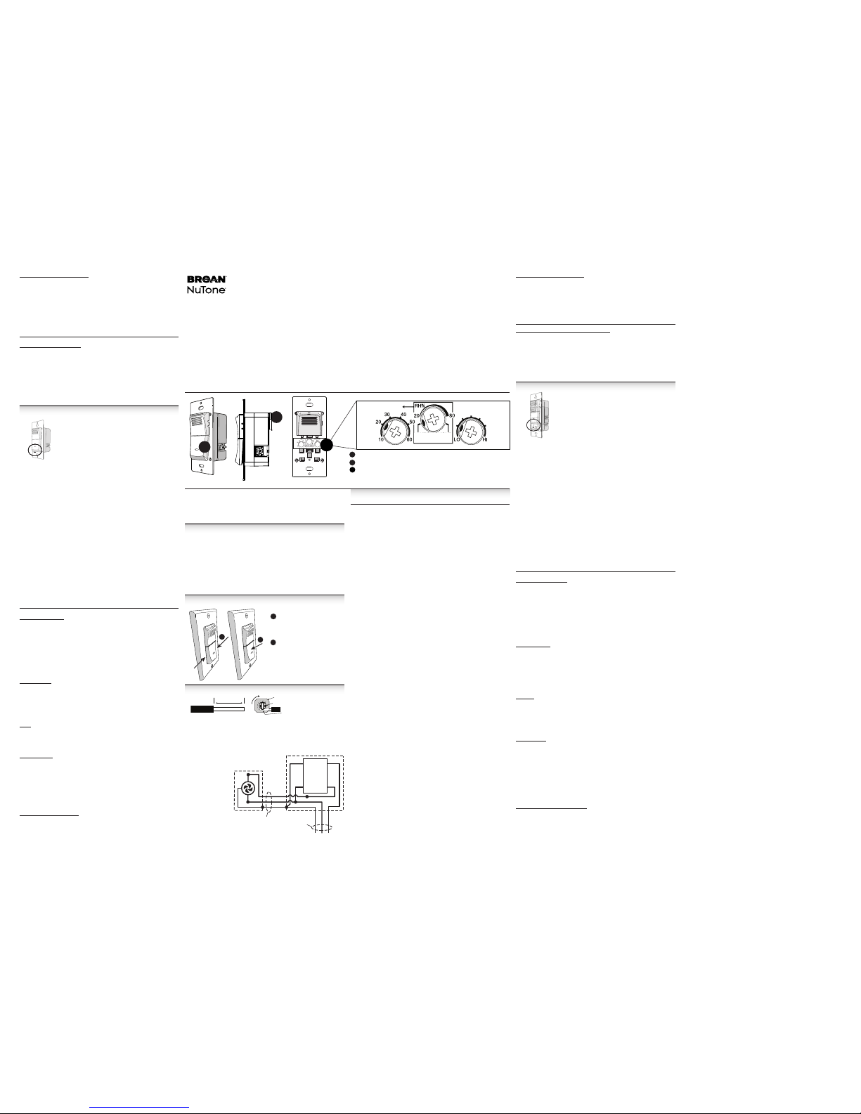
Interruptor y LED de encender/apagar (indicador de encendido/apagado del ventilador)
Cable de conexión a tierra
Ajustes del indicador ajustable del potenciómetro - Quite la tapa inferior en la cara
del control
B
C
C
(Se muestra el ajuste predeterminado de fábrica).
Modelo 82W
Control de Pared Detector de
Humedad Premium
AJUSTES DEL MODO DE CONTROL (AJUSTES DE POTENCIÓMETRO)
Potenciómetro AUTO SENSE / RH% / CYCLE (detección automática / % humedad relativa / ciclo):
• Modo AUTO SENSE (detección automática):
El control tiene un modo de detección automática (AUTO SENSE) el cual detecta los
cambios de aumento en el nivel de humedad (p. ej., detectar al aumentar). Una vez que
se alcanza el umbral, el ventilador de baño se activará en 2 minutos con el dispositivo
ubicado dentro de una distancia de 8 pies de la fuente de humedad (p.ej., la llave o
cabeza de regadera). La activación del ventilador puede tomar más tiempo si el Control
está ubicado a una distancia mayor que 8 pies de la fuente de humedad. El ventilador
permanecerá encendido basado en la función de TIME (tiempo) ajustada por el usuario
(ver descripción del potenciómetro TIME (teimpo)).
TIME (tiempo): ajustado por el usuario de 10 a 60 minutos por hora, en incrementos
de 10 minutos
AUTO SENSE / RH% / CYCLE (detección automática / % humedad relativa / ciclo):
AUTO SENSE (detección automática)
SENSITIVITY (sensibilidad): Activa; ajustada por el usuario de LO (baja) a HI (alta)
Función del control:
SENSE ON RISE (detectar al aumentar) está ACTIVA
SENSITIVITY (sensibilidad) está ACTIVA
• Modo CYCLE (ciclo de aire):
El control proporciona un TIME (tiempo) de encendido de ventilación pre ajustado
para cumplir con los códigos de ventilación continua. Después de que el tiempo
de encendido inicial se ajusta manualmente al encender el ventilador, el control
proporcionará ciclos de activación continuos cada hora. Asimismo, la función Sense
on Rise (detectar al aumentar) está activa en modo CYCLE (ciclo), de tal manera que
si el control está en la porción de “Fan OFF” (ventilador apagado) del ciclo y detecta un
aumento en la humedad, omitirá el recordatorio del ciclo de apagado e iniciará un nuevo
ciclo de encendido con una duración de tiempo igual al ajuste del potenciómetro TIME
(de tiempo).
Para calcular el ajuste del potenciómetro TIME (de tiempo) que corresponde, use esta
fórmula: ajuste del potenciómetro TIME = (CFM1 requerido ÷ CFM del ventilador) x 60
1 de la fórmula/tabla de ASHRAE 62.2 (con base en los pies cuadrados y el número de
habitaciones)
TIME (tiempo): ajustado por el usuario de 10 a 60 minutos por hora, en incrementos de
10 minutos
AUTO SENSE / RH% / CYCLE (detección automática / % humedad relativa /
ciclo): CYCLE (ciclo)
SENSITIVITY (sensibilidad): Activa; ajustada por el usuario de LO (baja) a HI (alta)
Función del control:
SENSE ON RISE (detectar al aumentar) está ACTIVA
SENSITIVITY (sensibilidad) está ACTIVA
• Modo RH% (humidistato):
El control tiene un modo de RH% (% de humedad relativa) con un nivel de humedad
relativa de umbral ajustado por el usuario. El ajuste de RH% se puede ajustar de 20
a 80 % de humedad relativa en el 10% de HR incrementos. Una vez que se alcanza
el umbral, o si SENSE ON RISE (detectar al aumentar) detecta un aumento en la
humedad, el ventilador conectado se debe activar dentro de 2minutos con el dispositivo
ubicado dentro de una distancia de 8 pies de la fuente de humedad (p. ej., la llave
o cabeza de regadera). La activación del ventilador puede tomar más tiempo si el
Control está ubicado a una distancia mayor que 8pies de la fuente de humedad. El
ventilador permanecerá encendido basado en la función de TIME (tiempo) ajustado por
el usuario.
TIME (tiempo): ajustado por el usuario de 10 a 60 minutos por hora, en incrementos de
10 minutos
AUTO SENSE / RH% / CYCLE (detección automática / % humedad relativa /
ciclo): RH%; ajustado por el usuario de 20 a 80% en el 10% de HR incrementos.
SENSITIVITY (sensibilidad): Inactiva
Función del control:
SENSE ON RISE (detectar al aumentar) está ACTIVA
SENSITIVITY (sensibilidad) está INACTIVA
Cuando la humedad ambiente alcanza el ajuste del potenciómetro de RH%:
- El ventilador (y el LED) se encenderá
- Cuando el temporizador caduca, el ventilador (y el LED) se apagará hasta que
ocurra otro evento, o si sigue ocurriendo (p. ej., la humedad del ambiente sigue
en o por arriba del valor de ajuste de RH% (% humedad relativa), la humedad del
ambiente alcanza el valor de ajuste de RH% nuevamente o si la función Sense
on Rise (detectar al aumentar) detecta un aumento en el nivel de humedad).
Potenciómetro TIME (de tiempo):
El potenciómetro TIME (de tiempo) se usa para configurar al ventilador que funcione
cada vez que se enciende el ventilador. Puede ajustarse para que funcione entre 10
y 60 minutos, en incrementos de 10 minutos. En modo CYCLE (Ciclo), la selección
TIME (Tiempo) es la parte de cada hora que funcionará el ventilador, y el conteo
regresivo comienza cuando se selecciona el modo CYCLE y se enciende el
ventilador. En modo MANUAL, el conteo regresivo comienza cuando se enciende
el ventilador con el interruptor de encendido/apagado. En los modos AUTO SENSE
y RH%, (Detección automática y % de humedad relativa) el conteo regresivo
comienza cuando la humedad relativa deja de subir.
Potenciómetro SENSITIVITY (de sensibilidad):
El potenciómetro SENSITIVITY (de sensibilidad) se usa para ajustar la sensibilidad
del control al aire húmedo del ambiente y conforme al tamaño de la habitación. En
un ambiente de baja humedad y/o en una habitación grande, puede ser necesario
ajustar el potenciómetro SENSITIVITY (de sensibilidad) a un ajuste más alto, MED
(medio) a HI (alto), para aumentar la sensibilidad del control para la detección de
humedad. En un ambiente de alta humedad y/o en una habitación pequeña, puede
ser necesario ajustar el potenciómetro SENSITIVITY (de sensibilidad) a un ajuste
más bajo, LO (bajo) a MED (medio), para reducir la sensibilidad del control para la
detección de humedad y para prevenir activaciones no deseadas.
MODO DE FUNCIONAMIENTO MANUAL
Nota: Independientemente de todos los demás ajustes, el LED azul
del panel frontal siempre estará encendido cuando el ventilador está
encendido, y se apagará cuando el ventilador esté apagado.
El control tiene un modo de operación manual con capacidad para
encender o apagar el ventilador a discreción del usuario. Presione y suelte
el interruptor inferior del control para encender o apagar el ventilador.
Adicionalmente a apagar manualmente el ventilador, el modo manual
también utiliza la función de apagado automático con la duración de
tiempo de encendido del ventilador ajustada por el usuario, como se
describe anteriormente en la sección Potenciómetro TIME (de tiempo). Con esta función, el
usuario puede encender manualmente el ventilador y no preocuparse por apagar manualmente el
ventilador, ya que la función TIME apagará el ventilador automáticamente.
El modo manual substituirá el mando de los modos AUTO SENSE / RH% / CYCLE (detección
automática / % humedad relativa / ciclo) cuando esté activo. Este ajuste de modo apagará todos los
valores de ajuste del usuario, con excepción del ajuste de TIME (tiempo), hasta que el interruptor
sea apagado manualmente o cuando el interruptor se apague automáticamente debido a la cuenta
regresiva de TIME (tiempo), tiempo en el cual la unidad regresará a los ajustes de los modos
anteriores después de un retardo de 5 minutos.
En otras palabras, si el ventilador se enciende manualmente y luego se apaga manualmente (o
debido a que la cuenta regresiva de TIME completa su ciclo), y si el ajuste anterior fue de RH%,
entonces después de un retardo de 5 minutos el control regresará al ajuste de RH% y encenderá
el ventilador si el valor de ajuste de RH es alcanzado, superado o si el Control detecta la relación
de aumento apropiada de humedad.
Si el ajuste anterior fue AUTO, el control encenderá el ventilador (después de un retardo de
5 minutos) si el control detecta una relación de aumento apropiada de humedad.
TIME (tiempo): ajustado por el usuario de 10 a 60 minutos por hora, en incrementos de 10 minutos
AUTO SENSE / RH% / CYCLE (detección automática / % humedad relativa / ciclo): Inactiva
SENSITIVITY (sensibilidad): Inactiva
Función del control:
Independientemente del MODO en que esté la unidad, al presionar el interruptor del panel frontal
substituye el mando de ese modo para encender inmediatamente el ventilador si estaba apagado,
o para apagarlo si estaba encendido.
Garantía limitada
Periodo y exclusiones de la garantía: Broan-NuTone LLC (la “Compañía”) garantiza al consumidor comprador original de
su producto (“usted”) que el producto (el “Producto”) no tendrá defectos en materiales o en mano de obra, por un periodo
de un (1) año a partir de la fecha de compra original.
El periodo de garantía limitada para cualquier pieza de repuesto proporcionada por la Compañía y para cualquier Producto
reparado o reemplazado conforme a esta garantía limitada, debe ser lo que reste del periodo de garantía original.
Esta garantía no cubre cartuchos de repelente ni repuestos de cartucho de repelente que se puedan comprar por
separado para instalarse en el producto. Esta garantía tampoco cubre (a) mantenimiento y servicio normal, (b) desgaste y
deterioro normal, (c) Productos o piezas que hayan sido sometidos a mal uso, abuso, uso anormal, negligencia, accidente,
mantenimiento, almacenamiento o reparaciones inadecuadas o insuficientes (excepto las reparaciones por parte de la
Compañía), (d) daños causados por instalación deficiente, o por instalación o uso contrario a las recomendaciones o
instrucciones, (e) daños causados por exposición a ambientes salinos, (f) daños durante el transporte, (g) desgaste natural
del acabado, (h) Productos en uso comercial o no residencial, o (i) daños causados por incendio, inundación u otras
causas de fuerza mayor. Esta garantía cubre únicamente los Productos vendidos por la Compañía a usuarios originales o
distribuidores autorizados en los Estados Unidos.
Esta garantía sustituye todas las garantías anteriores y no es transferible del comprador consumidor original.
No hay otras garantías: Esta Garantía limitada contiene la única obligación de la Compañía y su única reparación para
los productos defectuosos. Las garantías antes mencionadas son exclusivas y reemplazan cualquier otra garantía, expresa
o implícita. LA COMPAÑÍA RENUNCIA Y EXCLUYE TODAS LAS DEMÁS GARANTÍA EXPRESAS, Y RENUNCIA
Y EXCLUYE TODAS LAS GARANTÍAS IMPLÍCITAS POR LEY, INCLUIDAS PERO NO LIMITADAS A, LAS DE
COMERCIALIZACIÓN Y APTITUD PARA UN PROPÓSITO EN PARTICULAR. Hasta donde la ley aplicable prohíba la
exclusión de garantías implícitas, la duración de cualquier garantía implícita aplicable está limitada al periodo especificado
para la garantía expresa antes mencionada. Algunos estados no permiten limitaciones en la duración de una garantía
implícita, por lo que la limitación antes mencionada puede no aplicar en su caso. Cualquier descripción verbal o escrita del
Producto es para el único propósito de identificarlo y no deberá interpretarse como garantía expresa.
Siempre que sea posible, toda disposición de esta Garantía limitada deberá ser interpretada de tal manera que sea
aplicable y válida de conformidad con la ley correspondiente, pero en caso de que alguna disposición sea considerada
inaplicable o no válida, dicha disposición no será aplicable únicamente hasta el alcance de dicha prohibición o invalidez,
sin invalidar el resto de dicha disposición ni las demás disposiciones de la Garantía limitada.
Reparación: Durante el periodo de garantía limitada aplicable, la Compañía, a su opción, proporcionará piezas de
repuesto, o reparará o reemplazará, sin cargo alguno, cualquier Producto o pieza del mismo, hasta donde la Compañía
determine que está cubierto bajo esta garantía limitada y en violación de la misma bajo condiciones de uso y servicio
normales. La Compañía le enviará el Producto o las piezas de repuesto reparadas o reemplazadas sin cargo. Usted es
responsable de todos los costos de remoción, reinstalación y envío, seguro u otros cargos de flete incurridos en el envío
del Producto o pieza a la Compañía. Si debe enviar el Producto o la pieza a la Compañía, tal como lo indique la Compañía,
debe empaquetar adecuadamente el Producto o la pieza: la Compañía no se hace responsable por los daños durante el
transporte. La Compañía se reserva el derecho de utilizar Productos o piezas reacondicionados, reconstruidos, reparados
o refabricados en el proceso de reemplazo o reparación de garantía. Dichos Productos y piezas serán comparables
enfunción y rendimiento con un Producto o una pieza original y tendrán garantía durante el resto del periodo de la
garantía original.
Exclusión de daños: LA OBLIGACIÓN DE LA COMPAÑÍA DE SUMINISTRAR PIEZAS DE REPUESTO, O DE
REPARAR O REEMPLAZAR, A OPCIÓN DE LA COMPAÑÍA, SERÁ SU ÚNICA Y EXCLUSIVA REPARACIÓN DE
CONFORMIDAD CON ESTA GARANTÍA LIMITADA, Y LA ÚNICA Y EXCLUSIVA OBLIGACIÓN DE LA COMPAÑÍA. LA
COMPAÑÍA NO SERÁ RESPONSABLE POR DAÑOS INDIRECTOS, ACCESORIOS O PERJUICIOS OCASIONADOS
POR O EN RELACIÓN CON EL PRODUCTO, SU USO O RENDIMIENTO.
Algunos estados no permiten la exclusión o limitación de daños y perjuicios, por lo que la limitación o exclusión antes
mencionada podría no aplicar a usted. Esta garantía le otorga derechos legales específicos, y usted podría tener otros
derechos que varían de un estado a otro.
Esta garantía cubre únicamente el reemplazo o la reparación de Productos o piezas defectuosas en las instalaciones
principales de la Compañía, y no incluye el costo del viaje para servicio en campo ni los viáticos.
Cualquier asistencia que proporcione o procure la Compañía para usted fuera de los términos, limitaciones o exclusiones
de esta garantía limitada no constituirá una renuncia a dichos términos, limitaciones o exclusiones, ni dicha asistencia
extenderá o renovará la garantía.
La Compañía no le reembolsará ningún gasto en el que usted haya incurrido al reparar o reemplazar cualquier Producto
defectuoso, excepto los incurridos con autorización previa por escrito de la Compañía.
Cómo obtener el servicio cubierto por la garantía: Para tener derecho al servicio cubierto por la garantía, usted debe
(a) notificar a la Compañía a la dirección o número de teléfono que aparecen a continuación en un plazo de siete (7) días
a partir de descubrir el defecto cubierto, (b) proporcionar el número de modelo y la identificación de la pieza, y (c) describir
la naturaleza de cualquier defecto en el Producto o la pieza. Al momento de solicitar el servicio cubierto por la garantía,
debe presentar un comprobante de la fecha de compra original. Si usted no puede presentar una copia de la garantía
limitada original escrita, entonces regirán los términos de la garantía limitada escrita más actualizada de la compañía
para su producto en particular. Las garantías limitadas escritas más actualizadas para los productos de la Compañía se
pueden encontrar en www.broan.com.
Broan-NuTone LLC 926 West State Street, Hartford, WI 53027 www.broan.com 800-637-1453
TIME (tiempo)
SENSITIVITY MED
(sensibilidad media)
AUTO SENSE
(detección
automática)
CYCLE
(ciclo minutos/
hora)
A
Remoción:
• Agarre l a tapa inferior por
loslados y jale d irectamente
hacia afuera.
B
Instalación:
• Aline e las orejas en la
tapa con los agu jeros en
el panel metáli co y empuje
directamente hacia adentro.
B
A
INSTALACIÓN D E CABLES Y DIAGRAM A DE CABLEADO
Los terminale s de los cables acep tan cables de hast a #12 AWG MÁX sólidos y
trenzados.
1. Retire la combi nación de tornil lo/arandela del te rminal.
2. Enrolle el extre mo pelado del cab le alrededor de la r osca del tornill o - debajo de la
arandela.
3. Vuelva a instalar el tornillo/arandela asegurándose de que el cable permanezca
debajo de la aran dela.
Apriete los terminales
a 1.8 - 2.2 N-m
(15.9 - 19.5 in lb).
4. Nota: Los tornil los/
arandelas no están
diseñados para
insertar directamente
el cable pelad o. Use
solamente cable con
su extremo dob lado
en forma de “J” y
enróllelo alrededor de
la rosca del tor nillo para
obtener una conexión mecánica
y eléctrica adecuada.
Câble
3/4 pulg. (1.9cm)
Arandela
Tornillo
Cable debajo de la cabeza
del tornillo y de la arandela
NEGRO
BLANCO
TIERRA
VENTILADOR
CAJA DEL INTERRUPTOR
120 VAC
LINE IN
BLANCO
TIERRA
NEGRO
NEGRO
NEGRO
VENTILADOR
(CARGA)
CALIENTE
(LÍNEA)
NEUTRO
TIERRA
BLANCO
VERDE
CONTROL
DE HUMEDAD
2 CABLES
MÁS TIERRA
2 CABLES
MÁS TIERRA
 Loading...