

Page 1
MODEL 765H110L
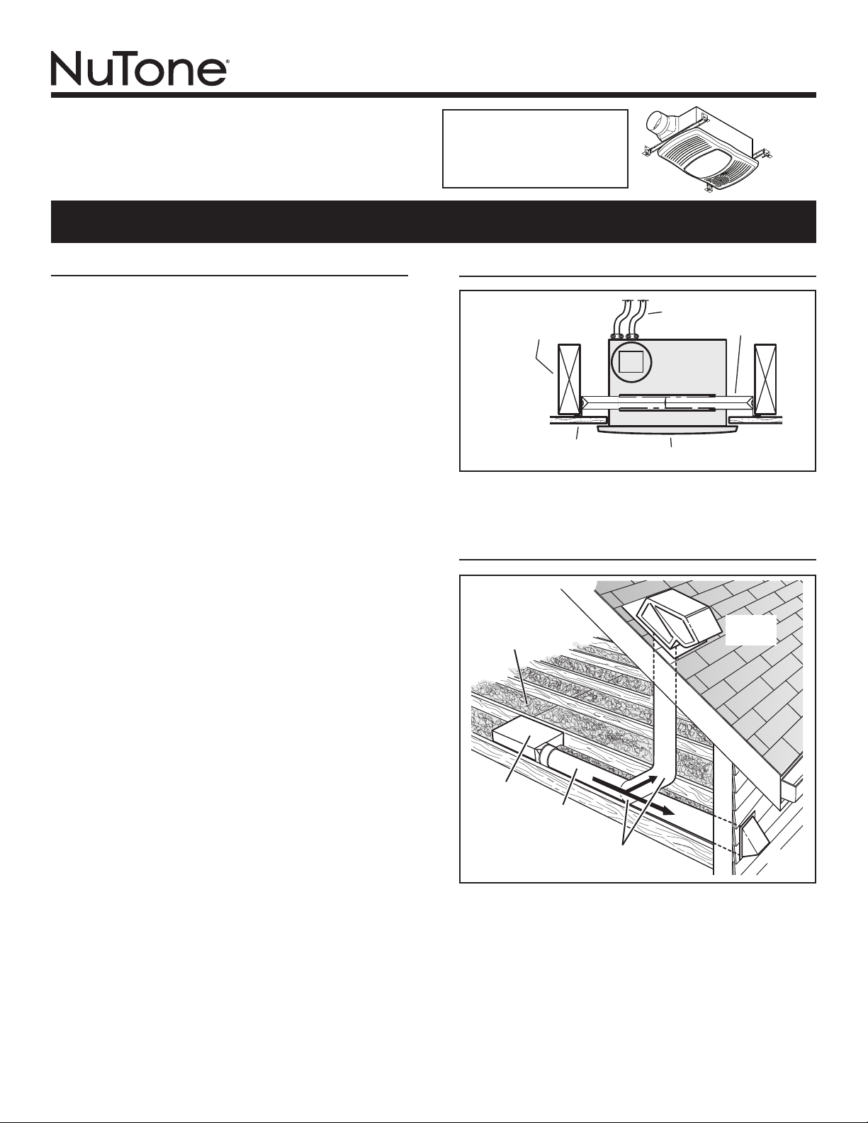
HOUSING
CEILING
JOIST, TRUSS,
OR I-JOISTS
MOUNTING
CHANNELS
GRILLE
CEILING
MATERIAL
POWER
CABLES
VENTILATION FAN
WITH HEATER & LIGHT
IMPORTANT INSTRUCTIONS
READ ALL INSTRUCTIONS BEFORE INSTALLING OR
USING THIS HEATER.
To reduce the risk of fire, electric shock, or injury to persons, observe the
following:
1. Use this unit only in the manner intended by the manufacturer. If you have
2. Before servicing or cleaning unit, switch power off at service panel and
3. Installation work and electrical wiring must be done by a qualified
4. When cutting or drilling into wall or ceiling, do not damage electrical wiring
5. This heater is hot when in use. To avoid burns, do not let bare skin touch
6. Extreme caution is necessary when any heater is used by or near chil-
7. Do not operate any heater after it malfunctions. Disconnect power at ser-
8. Do not use outdoors.
9. To disconnect heater, turn controls to off, and turn off power to heater
10. Do not insert or allow foreign objects to enter any ventilation or exhaust
11. To prevent a possible fire, do not block air intakes or exhaust in any man-
12. A heater has hot and arcing or sparking parts inside. Do not use it in
13. Use this heater only as described in this manual. Any other use not rec-
14. This product must be grounded.
15. Do not install heater in a tub or shower enclosure.
16. THIS PRODUCT MUST BE MOUNTED IN A FLAT CEILING ONLY. In-
17. Install heater in ceiling only - at least 6 inches from any wall.
18. Do not connect heater to dimmer switch or speed control.
19. Provide a separate 20 AMP circuit. Use 12 GA. power cable of type which
20. For greatest efficiency, install heater so heat is directed toward tub or
SAVE THESE INSTRUCTIONS
For Warranty Statement, Service
Parts, Technical Support, or to
Register your product, please
visit our website or call:
NuTone.com 888-336-6151.
READ AND SAVE THESE INSTRUCTIONS
TYPICAL INSTALLATION
questions, contact the manufacturer at the address or telephone number
listed in the warranty.
lock the service disconnecting means to prevent power from being
switched on accidentally. When the service disconnecting means cannot
be locked, securely fasten a prominent warning device, such as a tag, to
the service panel.
person(s) in accordance with all applicable codes and standards, including fire-rated construction codes and standards.
and other hidden utilities.
hot surfaces. Keep combustible materials, such as furniture, pillows, bedding, papers, clothes, etc. and curtains at least 3 feet (0.9 m) from the
front of the heater.
dren or invalids and whenever the heater is left operating and unattended.
vice panel and have heater inspected by a reputable electrician before
reusing.
circuit at main disconnect panel (or operate internal disconnect switch, if
provided).
opening, as this may cause an electric shock or fire, or damage the heater.
ner.
areas where gasoline, paint, or flammable vapors or liquids are used or
stored.
ommended by the manufacturer may cause fire, electric shock, or injury
to persons.
stallations in ceilings 9-feet high or less will provide maximum comfort.
DO NOT MOUNT THIS PRODUCT IN A WALL.
meets code. Use supply wiring rated for at least 90OC.
shower area. Avoid directing toward walls or windows.
Housing mounted to joists, trusses, or I-joists.
Up to 24-inches on-center.
PLAN THE INSTALLATION
INSULATION
(Can be placed
around and over
housing.)
HOUSING
4-IN.
ROUND
Purchase
*
separately
The unit will operate most quietly and efficiently when located
where the shortest possible duct run and minimum number of
elbows will be needed.
Use a roof cap or wall cap that has a built-in damper to reduce
backdrafts.
Plan to supply the unit with proper line voltage and appropriate
power cable.
DUCT *
4-IN. ROUND
ELBOW(S) *
ROOF
CAP
Page 1
*
WALL
CAP
*
Page 2

MODEL 765H110L
GREEN
WHITE
to
WHITE
HEAT
LIGHT
GROUND
120 VAC LINE IN
BLACK
BLACK
FAN
RED
WIRING PLATE
FROM VENTILATOR
VENTILATOR
HOUSING
LIGHT
&
FANHEAT
BLACK to BLACK
(Fan)
WHITE to WHITE
RED to BLUE
(Light)
BLACK to RED
(Heat)
WHITE to WHITE
BLACK
Page 2
INSTALLATION
WARNING: To reduce the risk of fire, do not store or use
gasoline or other flammable vapors and liquids in the vicinity
of the heater.
CAUTION: High temperature, risk of fire, keep electrical cords,
drapery, furnishings, and other combustibles at least 3 feet
(0.9 m) from the front of the heater and away from the side
and rear.
HANGER
BARS
CHANNEL
CHANNEL
1. Insert hanger bars.
Four (4) sliding hanger bars are provided to allow for
accurate positioning of housing anywhere between
framing. They can be used on all types of framing (I-joist,
standard joist, and truss construction) and span up to 24”.
Slide hanger bars into channels on housing. Make sure
hanger bar tabs face “up” as shown.
HOLE FOR OPTIONAL
SCREW MOUNTING (4)
TAB
HANGER
BARS
* SCREW (2)
3. Attach
damper
/ duct
connector to
housing.
Snap damper /
duct connector
onto housing.
Make sure
connector is flush
with top of housing
and damper flap
falls closed.
4. Install
4-inch round
ductwork.
Connect 4-inch
round ductwork
to damper / duct
connector. Run
ductwork to a roof
cap or wall cap.
Tape all ductwork
connections to
make them secure
and air tight.
CONNECT WIRING
Installation work and electrical wiring must be done by a qualified person(s) in accordance with all applicable codes and standards, including fire-rated construction codes and standards.
2. Mount housing.
Extend hanger bars to the width of the framing. Hold fan
Nail fan to framing or fasten with screws (not provided)
* To ensure a noise-free mount: Secure hanger bars
NAIL (4)
in place with the hanger bar tabs wrapping around the
bottom edge of the framing.
through holes near nails.
together with screws or use a pliers to crimp mounting
channels tightly around hanger bars.
BOTTOM EDGE
OF FRAMING
CAUTION
RATING
SPECIFICATIONS
Each two-position
rocker switch is rated 15
A @ 120VAC. The total
load on this control must
not exceed 20 A @ 120VAC.
Page 3
BLU
BLK
BLK
WHT
WHT
WHT
RED
WHT
GRD
UNIT
LIGHT
SWITCH
VENT
SWITCH
HEAT
SWITCH
LINE
IN
RED
BLK
WHT
BLK
WHT
GRD
SWITCH BOX
LIGHT
VENT
HEAT
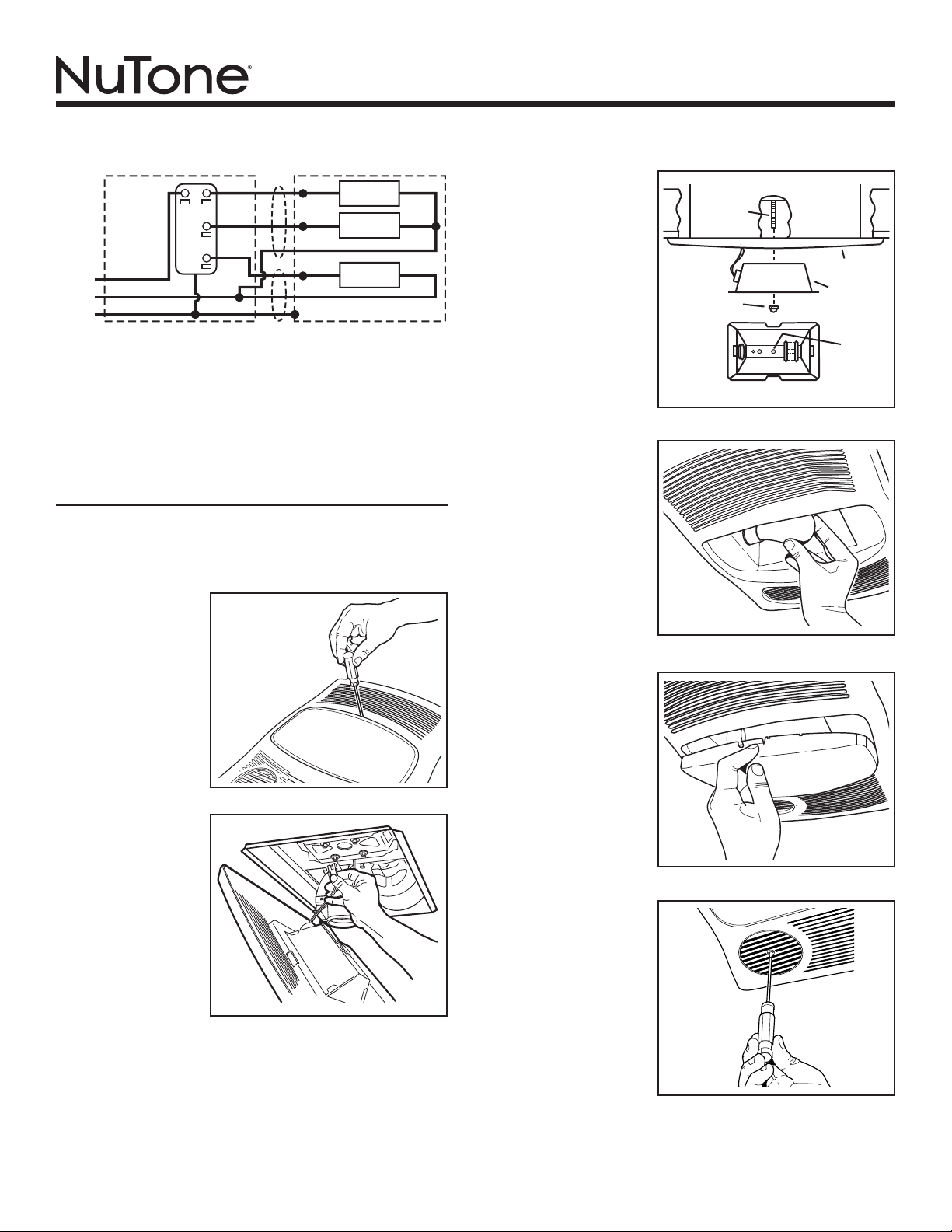
5. Connect electrical wiring.
Run 120 VAC house wiring to installation location. Use
proper UL approved connectors to secure house wiring to
wiring plate. Connect wires as shown in wiring diagram(s).
INSTALL GRILLE & BULB
6. Finish ceiling.
Install ceiling material. Cut out ceiling material closely
around housing.
7. Remove
light lens
from grille.
Insert a small
flat-bladed
screwdriver into
the slot at one
end of the light
lens. Carefully pry
the lens out.
8. Plug-in
light.
Hold grille
assembly up near
housing. Connect
light plug from
grille assembly to
receptacle inside
of housing.
9. Attach
grille.
Place grille/
reflector
combination
over protruding
screw and
fasten in place
using acorn nut
provided. HAND
TIGHTEN acorn
nut 1/4 turn after
it is snug.
10. Install
bulb.
The unit
accepts a
100-Watt
(maximum) E26
base bulb. (Bulb
not included.)
11. Attach
light lens.
Hook the tabs
on one end of
the lens into the
slot in the grille.
Lift other end
of lens up and
snap into place.
12. Rotate
heater
grille.
Use a flat-bladed
screwdriver to
rotate the round
heater grille to
provide heat
in the desired
direction.
SCREW
ACORN NUT
MODEL 765H110L
Page 3
GRILLE
LIGHT
REFLECTOR
USE
THIS
HOLE
BOTTOM VIEW
Page 4
OPERATION
Before using heater, make sure heater has been properly installed
according to installation steps beginning with the "TYPICAL INSTALLATION" section on page 1.
Use a 3-Function Control to operate the heater, fan, and light
separately. See “Connect Wiring” for details.
MODEL 765H110L
Page 4
Page 5

MAINTENANCE
The following maintenance and cleaning tasks can be performed
by the user. All other servicing must be performed by an authorized technician If you have any questions, please consult with
our customer service department at: 800-558-1711.
TO REPLACE BULB
Remove lens by gently depressing sides and pull down. Use a
maximum 100-Watt E26 base bulb.
LUBRICATION
The heater is permanently lubricated and never needs oiling or
disassembly.
CLEANING
Clean heater once a month as follows:
1. Turn off power at service panel.
2. Make sure heating element is cool.
3. Use a soft brush attachment to gently vacuum grille openings
or wipe grille clean with a soft cloth.
4. Restore power.
CAUTION: METAL AND ELECTRICAL PARTS SHOULD NEVER
BE IMMERSED IN WATER.
MODEL 765H110L
Page 5
WARRANTY
Limited Warranty
Warranty Period and Exclusions: Broan-NuTone LLC (the “Company”) warrants to the original consumer purchaser of its product (“you”) that the product (the “Product”) will be free from material
defects in the Product or its workmanship for a period of one (1) year from the date of original purchase.
The limited warranty period for any replacement parts provided by the Company and for any Products repaired or replaced under this limited warranty shall be the remainder of the original warranty
period.
This warranty does not cover speed controls, uorescent lamp starters, tubes, halogen and incandescent bulbs, fuses, lters, ducts, roof caps, wall caps and other accessories for ducting that may
be purchased separately and installed with the Product. This warranty also does not cover (a) normal maintenance and service, (b) normal wear and tear, (c) any Products or parts which have been
subject to misuse, abuse, abnormal usage, negligence, accident, improper or insufcient maintenance, storage or repair (other than repair by the Company), (d) damage caused by faulty installation,
or installation or use contrary to recommendations or instructions, (e) any Product that has been moved from its original point of installation, (f) damage caused by environmental or natural elements,
(g) damage in transit, (h) natural wear of nish, (i) Products in commercial or nonresidential use, or (j) damage caused by re, ood or other act of God. This warranty covers only Products sold to
original consumers in the United States by the Company or U.S. distributors authorized by the Company.
This warranty supersedes all prior warranties and is not transferable from the original consumer purchaser.
No Other Warranties: This Limited Warranty contains the Company’s sole obligation and your sole remedy for defective products. The foregoing warranties are exclusive and in lieu of any other
warranties, express or implied. THE COMPANY DISCLAIMS AND EXCLUDES ALL OTHER EXPRESS WARRANTIES, AND DISCLAIMS AND EXCLUDES ALL WARRANTIES IMPLIED BY
LAW, INCLUDING WITHOUT LIMITATION THOSE OF MERCHANTABILITY AND FITNESS FOR A PARTICULAR PURPOSE. To the extent that applicable law prohibits the exclusion of implied
warranties, the duration of any applicable implied warranty is limited to the period specied for the express warranty above. Some states do not allow limitations on how long an implied warranty
lasts, so the above limitation may not apply to you. Any oral or written description of the Product is for the sole purpose of identifying it and shall not be construed as an express warranty.
Whenever possible, each provision of this Limited Warranty shall be interpreted in such manner as to be effective and valid under applicable law, but if any provision is held to be prohibited or invalid,
such provision shall be ineffective only to the extent of such prohibition or invalidity, without invalidating the remainder of such provision or the other remaining provisions of the Limited Warranty.
Remedy: During the applicable limited warranty period, the Company will, at its option, provide replacement parts for, or repair or replace, without charge, any Product or part thereof, to the extent
the Company nds it to be covered by and in breach of this limited warranty under normal use and service. The Company will ship the repaired or replaced Product or replacement parts to you at no
charge. You are responsible for all costs for removal, reinstallation and shipping, insurance or other freight charges incurred in the shipment of the Product or part to the Company. If you must send
the Product or part to the Company, as instructed by the Company, you must properly pack the Product or part—the Company is not responsible for damage in transit. The Company reserves the
right to utilize reconditioned, refurbished, repaired or remanufactured Products or parts in the warranty repair or replacement process. Such Products and parts will be comparable in function and
performance to an original Product or part and warranted for the remainder of the original warranty period.
Exclusion of Damages: THE COMPANY’S OBLIGATION TO PROVIDE REPLACEMENT PARTS, OR REPAIR OR REPLACE, AT THE COMPANY’S OPTION, SHALL BE YOUR SOLE AND
EXCLUSIVE REMEDY UNDER THIS LIMITED WARRANTY AND THE COMPANY’S SOLE AND EXCLUSIVE OBLIGATION. THE COMPANY SHALL NOT BE LIABLE FOR INCIDENTAL,
INDIRECT, CONSEQUENTIAL OR SPECIAL DAMAGES ARISING OUT OF OR IN CONNECTION WITH THE PRODUCT, ITS USE OR PERFORMANCE.
Some states do not allow the exclusion or limitation of incidental or consequential damages, so the above limitation or exclusion may not apply to you. This warranty gives you specic legal rights,
and you may also have other rights, which vary from state to state.
This warranty covers only replacement or repair of defective Products or parts thereof at the Company’s main facility and does not include the cost of eld service travel and living expenses.
Any assistance the Company provides to or procures for you outside the terms, limitations or exclusions of this limited warranty will not constitute a waiver of such terms, limitations or exclusions,
nor will such assistance extend or revive the warranty.
The Company will not reimburse you for any expenses incurred by you in repairing or replacing any defective Product, except for those incurred with the Company’s prior written permission.
How to Obtain Warranty Service: To qualify for warranty service, you must (a) notify the Company at the address or telephone number stated below within seven (7) days of discovering the covered
defect, (b) give the model number and part identication and (c) describe the nature of any defect in the Product or part. At the time of requesting warranty service, you must present evidence of
the original purchase date. If you cannot provide a copy of the original written limited warranty, then the terms of the Company’s most current written limited warranty for your particular product will
control. The most current limited written warranties for the Company’s products can be found at www.broan.com .
Broan-NuTone LLC 926 West State Street, Hartford, WI 53027 www.broan.com 800-637-1453
Page 6

MODEL 765H110L
Page 6
This page intentionally left blank.
1101136B
Page 7

MODELO 765H110L
CUBIERTA
VIGA DE TECHO,
TIRANTE O VIGA EN I
RANURAS DE
MONTAJE
REJILLA
MATERIAL
DEL TECHO
CABLES
ALIMENTADORES
VENTILADOR CON
CALEFACTOR Y LUZ
LEA Y CONSERVE ESTAS INSTRUCCIONES
INSTRUCCIONES IMPORTANTES
LEA TODAS LAS INSTRUCCIONES ANTES DE INSTALAR
O USAR ESTE CALENTADOR.
Para reducir el riesgo de incendios, descargas eléctricas o lesiones personales, observe
las siguientes precauciones:
1. Use la unidad solo de la manera indicada por el fabricante. Si tiene preguntas,
comuníquese con el fabricante a la dirección o al número telefónico que se incluye
en la garantía.
2. Antes de dar servicio a la unidad o de limpiarla, interrumpa el suministro eléctrico
en el panel de servicio y bloquee los medios de desconexión del servicio para evitar
que la electricidad se reanude accidentalmente. Cuando no sea posible bloquear
los medios de desconexión del servicio, fije firmemente una señal de advertencia
(como una etiqueta) en un lugar visible del panel de servicio.
3. El trabajo de instalación y el cableado eléctrico deben estar a cargo de personal
capacitado, de acuerdo con todos los códigos y normas correspondientes,
incluidos los códigos y normas de construcción específicos sobre protección contra
incendios.
4. Al cor tar o perforar a través de la pared o del cielo raso, tenga cuidado de no dañar
el cableado eléctrico ni otros servicios ocultos.
5. Este calentador se calienta cuando se usa. Para evitar quemaduras, no deje que
la piel desnuda toque las superficies calientes. Mantenga materiales combustibles
como muebles, almohadas, ropa de cama, papeles, ropa, etc., así como las
cortinas, por lo menos a 3 pies (0.9 m) de la parte delantera del calentador.
6. Es necesario tener extremo cuidado cuando se use un calentador cerca de niños o
personas inválidas, y siempre que el calentador se deje funcionando y sin atención.
7. No haga funcionar ningún calentador después de que presente una falla.
Desconecte la energía eléctrica en el panel de servicio y pida que un electricista
acreditado inspeccione el calentador antes de volverlo a usar.
8. No lo use en exteriores.
9. Para desconectar el calentador, mueva los controles a la posición de apagado y
desconecte la energía eléctrica al circuito del calentador en el panel de desconexión
principal (o active el interruptor de desconexión interna, si existe).
10. No inserte ni permita que objetos extraños entren en la abertura de ventilación
o de escape, pues esto puede ocasionar una descarga eléctrica, un incendio o
daños al calentador.
11. Para prevenir un posible incendio, no bloquee la entrada o salida del aire de ninguna
manera.
12. El calentador tiene piezas calientes y que pueden generar arcos eléctricos o
chispas en el interior. No lo use en áreas donde se use o almacene gasolina,
pintura o vapores o líquidos flamables.
13. Use este calentador solamente como se describe en este manual. Cualquier otro
uso no recomendado por el fabricante puede ocasionar un incendio, una descarga
eléctrica o lesiones a personas.
14. Este producto debe ser conectado a tierra.
15. No instale esta unidad sobre una bañera o ducha.
16. Este producto está diseñado para instalarse solamente en techos planos. El
confort óptimo se obtiene en instalaciones en techos de 9 pies (2.7 m) o menos.
NO MONTE ESTE PRODUCTO EN LA PARED.
17. Instálelo únicamente en techos, a distancias mínimas de 6 pulg. (15 cm) de
cualquier pared.
18. No conecte el calentador a un variador de luz o control de velocidad.
19. Proporcione un circuito por separado de 20 A. Utilice un cable eléctrico calibre
12 de un tipo conforme al código. Utilice un cable eléctrico clasificado para por lo
menos 90OC.
20. Para asegurar una mayor eficiencia, instale el calentador de manera que el calor
esté dirigido hacia el área de la bañera o ducha. Evite dirigir el calor hacia paredes
o ventanas.
GUARDE ESTAS INSTRUCCIONES
Si desea consultar la declaración de
garantía, repuestos de servicio, apoyo
técnico o para registrar su producto, visite
nuestro sitio web o llame:
NuTone.com 888-336-6151.
INSTALACIÓN TÍPICA
La cubierta se monta en las vigas, tirantes o vigas en I.
Hasta 24 pulg. (61 cm) de centro a centro.
PLANIFICACIÓN
AISLAMIENTO
(puede ponerse
alrededor de, y sobre
la cubierta)
CUBIERTA
CONDUCTO
REDONDO DE
4 PULG. *
* Se compra por
separado
El ventilador funcionará con más eficiencia y menos ruido si se
ubica en un sitio donde requiera el tramo de conductos más corto
posible y un mínimo número de codos.
Instale una tapa de techo o de pared que tenga un regulador de
tiro integrado a fin de reducir los contratiros.
Alimente la unidad con el voltaje de línea y el cable alimentador
apropiados.
CODO(S)
REDONDO(S)
DE 4 PULG. *
Página 7
TAPA DE
TECHO *
TAPA DE
PARED *
Page 8

MODELO 765H110L
VERDE
BLANCO con
BLANCO
CALOR
LUZ
TIERRA
LÍNEA DE ENTRADA
DE 120 VCA
NEGRO
NEGRO
VENTILADOR
ROJO
PLACA DE CABLEADO
DEL VENTILADOR
CUBIERTA DEL
VENTILADOR
LUZ
Y
VENTILADORCALOR
NEGRO con
NEGRO (ventilador)
BLANCO con
BLANCO
ROJO con
AZUL (luz)
NEGRO con
ROJO (calor)
BLANCO con
BLANCO
NEGRO
Página 8
INSTALACIÓN
ADVERTENCIA: Para reducir el riesgo de incendio, no almacene
ni use gasolina u otros vapores y líquidos flamables en las
cercanías del calentador.
PRECAUCIÓN: Temperatura alta, el riesgo de incendio, mantenga
los cables eléctricos, cortinas, muebles y otros materiales
combustibles por lo menos 3 pies (0,9 m) del frente del calentador
y lejos de la cara y la parte trasera.
BARRAS DE
SUSPENSIÓN
CANAL
CANAL
1. Inserte las barras de suspensión.
Se proporcionan cuatro (4) barras de suspensión deslizantes
para facilitar la colocación adecuada de la cubierta en cualquier
parte entre la estructura. Estas barras se adaptan a toda clase de
estructuras (construcciones de vigas “I”, vigas estándar y tirantes) y
se extienden a un máximo de 24 pulg. (61 cm).
Deslice las barras de suspensión en los canales de la cubierta.
Asegúrese de que las lengüetas de las barras de suspensión estén
de cara hacia arriba, tal como se muestra.
ORIFICIO PARA MONTAJE
OPCIONAL CON TORNILLO (4)
LENGÜETA
BARRAS DE
SUSPENSIÓN
TORNILLO (2)
*
3. Acople el
conector del
regulador
de tiro/
conducto a
la cubierta.
Conecte a presión
el
conectador del
regulador
de tiro/
conducto en la
cubierta. Asegúrese
de que el conector esté al
la aleta del regulador
ras con la parte superior
caiga cerrada.
de la cubierta y que
4. Instale el
conducto
redondo de
4 pulg.
Conecte el conducto
redondo de 4 pulg.
al conector del
regulador/conducto.
Extienda el conducto
hacia una tapa de
techo o tapa
de pared. Encinte
todas
las conexiones
de los conductos
para fijarlas y hacerlas herméticas al aire.
CONEXIÓN ELÉCTRICA
El trabajo de instalación y el cableado eléctrico deben estar a
cargo de personal capacitado, de acuerdo con todos los códigos y normas correspondientes, incluidos los códigos y normas
de construcción especícos sobre protección contra incendios.
2. Monte la cubierta.
* Para lograr un montaje silencioso: acople y fije las barras de
CLAVO (4)
Abra las barras de suspensión hasta el ancho de la estructura.
Sostenga el ventilador en su sitio envolviendo las lengüetas de
las barras de suspensión alrededor del borde inferior de la
estructura.
BORDE INFERIOR DE
LA ESTRUCTURA
Clave el ventilador a la estructura o sujételo con tornillos (no
incluidos)
suspensión con tornillos, o con un alicate doble los canales de
montaje bien justos alrededor de las barras de suspensión.
a través de los orificios que están cerca de los clavos.
PRECAUCIÓN
CAPACIDAD
NOMINAL
Cada interruptor
oscilante de dos
posiciones tiene una capacidad nominal de
15 A a 120 VCA. La carga total de
este control no puede ser mayor de 20 A a 120 VCA.
Page 9

5. Conecte los cables eléctricos.
AZUL
NEGRO
BLANCO
TIERRA
UNIDAD
INTERRUPTOR
DE
LUZ
INTERRUPTOR
DEL VENTILADOR
INTERRUPTOR
DEL CALEFACTOR
LÍNAEA DE
ENTRADA
R OJO
NEGRO
NEGRO
BLANCO
BLANCO
BLANCO
BLANCO
R OJO
TIERRA
BLANCO
NEGRO
CAJA DE INTERRUPTOR DOBLE
LUZ
VENTILADOR
CALOR
Extienda el cableado de la casa de 120 VCA al lugar de la instalación.
Utilice conexiones aprobadas por UL para asegurar el cableado de la
casa a la placa de cableado. Conecte los cables tal como se ilustra en
los diagramas de cableado.
INSTALE LA REJILLA Y
LA BOMBILLA
6. Termine el techo.
Instale el material del techo. Corte el material del techo alrededor de la
cubierta.
7. Quite la
lente de luz
de la rejilla.
Inserte un pequeño
destornillador plano
en la rejilla en un
extremo de la lente de
luz. Haga palanca con
cuidado para retirar la
lente.
8. Conecte
la luz.
Sostenga el conjunto
de la rejilla cerca de
la cubierta. Conecte
el enchufe de la luz
del conjunto de la
rejilla al receptáculo
dentro de la cubierta.
9. Fije la
rejilla.
Coloque el conjunto
rejilla/reflector
sobre el tornillo que
sobresale, y fíjelo
usando la tuerca
de caperuza que
se proporciona.
APRIETE CON LA
MANO la tuerca
de caperuza ¼ de
vuelta después de
que
esté ajustada.
10. Instale la
bombilla.
La unidad acepta
una bombilla
incandescente
de 100 watts
(máximo)
bombilla de base
E26. (Bombilla no
incluida).
11.
Fije la lente
de luz.
Enganche las
lengüetas por
un extremo de la
lente en la ranura
de la rejilla.
Levante el otro
extremo de la
lente y fíjela en su
lugar.
12. Gire la
rejilla del
calefactor.
Con un
destornillador
plano, gire la rejilla
del calefactor
redonda para
proporcionar
calefacción en la
dirección deseada.
MODELO 765H110L
TORNILLO
TUERCA DE
CAPERUZA
VISTA INFERIOR
Página 9
REJILLA
REFLECTOR
DE LUZ
UTILICE
ESTE
ORIFICIO
Page 10

OPERACIÓN
Antes de usar el calentador, asegúrese de que esté instalado adecuadamente, de acuerdo con los pasos de instalación indicados
en “INSTALACIÓN TYPICA” en la página 7.
Utilice un control de 3 funciones para operar el calefactor, el
ventilador y la luz por separado (vea los detalles en la sección
“Conexión eléctrica”).
MODELO 765H110L
Página 10
Page 11

MANTENIMIENTO
El usuario puede realizar las siguientes tareas de mantenimiento
y limpieza. Todos los demás servicios los debe realizar un técnico
autorizado. Si tiene preguntas, consulte a nuestro departamento
de servicio al cliente llamando al: 800-558- 1711.
PARA REEMPLAZAR LA LAMPARA
Quite el lente, presionando suavemente los lados y empuje. Use
una bombilla incandescente de 100 watts (máximo) bombilla de
base E26.
LUBRICACIÓN
El calentador está permanentemente lubricado y nunca necesitará ponerle aceite ni desarmarlo.
LIMPIEZA
Limpie el calentador una vez al mes tal como sigue:
1. Apague la energía eléctrica en el panel de servicio.
2. Asegúrese de que el elemento de calefacción esté frío.
3. Use un aditamento de cepillo suave para aspirar suavemente
aberturas de la rejilla o limpie la rejilla con un paño suave.
4. Restaure la energía eléctrica.
CUIDADO: LAS PIEZAS METALICAS Y ELECTRICAS NUNCA
SE DEBEN SUMERGIR EN AGUA.
MODELO 765H110L
Página 11
GARANTÍA
Periodo y exclusiones de la garantía: Broan-NuTone LLC (la “Compañía”) garantiza al consumidor comprador original de su producto (“usted”) que el producto (el “Producto”) estará libre de defectos en
materiales o en mano de obra, por un periodo de un (1) año a partir de la fecha de compra original.
El periodo de garantía limitada para cualquier pieza de repuesto proporcionada por la compañía y para cualquier Producto reparado o reemplazado bajo esta garantía limitada debe ser lo que reste del periodo
de garantía original.
Esta garantía no cubre controles de velocidad, arrancadores de lámparas uorescentes, tubos, bombillas de halógeno e incandescentes, fusibles, ltros, conductos, tapas de techo, tapas de pared ni otros
accesorios que pudieran ser comprados por separado e instalados con el producto. Esta garantía tampoco cubre (a) mantenimiento y servicio normal, (b) uso y desgaste normal, (c) Productos o piezas sujetos
a mal uso, abuso, uso anormal, negligencia, accidente, mantenimiento inadecuado o insuciente, almacenamiento o reparación (que no sea reparación por parte de la Compañía), (d) daños causados por
instalación defectuosa, o bien instalación o uso contrario a las recomendaciones o instrucciones, (e) cualquier Producto que se haya movido de su punto de instalación original, (f) daños ocasionados por el
medio ambiente o los elementos naturales, (g) daños en tránsito, (h) desgaste natural del acabado, (i) Productos en uso comercial o no residencial, o (j) daños ocasionados por incendio, inundación u otro
caso fortuito. Esta garantía cubre solamente Productos vendidos a clientes originales en los Estados Unidos por la Compañía o a distribuidores de EE. UU. autorizados por la Compañía.
Esta garantía sustituye todas las garantías anteriores y no es transferible del comprador consumidor original.
No hay otras garantías: Esta garantía limitada contiene la única obligación de la Compañía y su único recurso ante productos defectuosos. Las garantías anteriores son exclusivas y en lugar de cualquier
otra garantía, expresa o implícita. LA COMPAÑÍA NIEGA Y EXCLUYE CUALQUIER OTRA GARANTÍA EXPRESA, Y NIEGA Y EXCLUYE TODAS LAS GARANTÍAS IMPLÍCITAS POR LEY, INCLUYENDO,
ENTRE OTRAS, LAS DE COMERCIALIZACIÓN Y APTITUD PARA UN PROPÓSITO EN PARTICULAR. Hasta el grado en que la ley aplicable prohíba la exclusión de las garantías implícitas, la duración de
cualquier garantía implícita aplicable está limitada al periodo especicado para la garantía expresa antes mencionada. Algunos estados no permiten limitaciones en la duración de una garantía implícita, así
que la limitación anterior tal vez no aplique en su caso. Cualquier descripción verbal o escrita del Producto es para el único propósito de identicarlo y no deberá considerarse como una garantía expresa.
Siempre que sea posible, toda disposición de esta garantía limitada deberá ser interpretada de tal forma que sea efectiva y válida de conformidad con la ley aplicable, pero si alguna disposición fuera
considerada prohibida o inválida, quedará sin efecto solo en virtud de dicha prohibición o invalidez, sin invalidar el resto de dicha disposición o las demás disposiciones restantes de la garantía limitada.
Recurso: Durante el periodo de garantía limitada aplicable, la Compañía, a su opción, suministrará piezas de repuesto, o reparará o reemplazará, sin cargo alguno, cualquier Producto o pieza del mismo,
hasta el grado en que la Compañía lo encuentre cubierto bajo esta garantía limitada y en incumplimiento de la misma en condiciones normales de uso y servicio. La Compañía le enviará el Producto reparado
o reemplazado o las piezas de repuesto sin cargo. Usted es responsable de todos los costos de retiro, reinstalación y envío, seguro u otros cargos de ete incurridos en el envío del Producto o pieza a la
Compañía. Si debe enviar el Producto o la pieza a la Compañía, tal como lo indique la Compañía, debe empaquetar adecuadamente el Producto o la pieza: la Compañía no se hace responsable por los daños
en tránsito. La Compañía se reserva el derecho de utilizar Productos o piezas reacondicionados, renovados, reparados o refabricados en el proceso de reemplazo o reparación de garantía. Dichos Productos
y piezas serán comparables en función y desempeño a un Producto o una pieza original y tendrán garantía durante el resto del periodo de la garantía original.
Exclusión de daños: LA OBLIGACIÓN DE LA COMPAÑÍA DE SUMINISTRAR PIEZAS DE REPUESTO, O DE REPARAR O REEMPLAZAR, A OPCIÓN DE LA COMPAÑÍA, SERÁ SU ÚNICO Y EXCLUSIVO
RECURSO BAJO ESTA GARANTÍA LIMITADA, Y LA ÚNICA Y EXCLUSIVA OBLIGACIÓN DE LA COMPAÑÍA. LA COMPAÑÍA NO SERÁ RESPONSABLE POR DAÑOS INCIDENTALES, INDIRECTOS,
RESULTANTES O ESPECIALES QUE SURJAN POR EL USO O DESEMPEÑO DEL PRODUCTO, O EN RELACIÓN CON EL MISMO.
Algunos estados no permiten la exclusión o limitación de daños incidentales o resultantes, por lo que la limitación antes mencionada podría no aplicarse a usted. Esta garantía le otorga derechos legales
especícos, y usted podría tener otros derechos que varían de un estado a otro.
Esta garantía cubre únicamente el reemplazo o la reparación de Productos defectuosos o piezas de los mismos en la planta principal de la Compañía, y no incluye el costo del viaje para el servicio de campo
ni los viáticos.
Cualquier asistencia que proporcione o procure la Compañía para usted fuera de los términos, limitaciones o exclusiones de esta garantía limitada no constituirá una renuncia a dichos términos, limitaciones o
exclusiones, ni dicha asistencia extenderá o renovará la garantía.
La Compañía no le reembolsará ningún gasto en el que usted haya incurrido al reparar o reemplazar cualquier Producto defectuoso, excepto los incurridos con el permiso previo por escrito de la Compañía.
Cómo obtener el servicio cubierto por la garantía: Para tener derecho al servicio cubierto por la garantía, usted debe (a) noticar a la Compañía a la dirección o número de teléfono que aparecen abajo
en un plazo de siete (7) días después de descubrir el defecto cubierto, (b) proporcionar el número de modelo y la identicación de la pieza y (c) describir la naturaleza de cualquier defecto en el Producto o la
pieza. En el momento de solicitar el servicio cubierto por la garantía, debe presentar un comprobante de la fecha de compra original. Si usted no puede presentar una copia de la garantía limitada original por
escrito, entonces regirán los términos de la garantía limitada por escrito más actualizada de la compañía para su producto en particular. Las garantías limitadas por escrito más actualizadas para los productos
de la Compañía se pueden encontrar en www.broan.com.
Broan-NuTone LLC 926 West State Street, Hartford, WI 53027 www.broan.com 800-637-1453
Garantía limitada
Page 12

MODELO 765H110L
Página 12
Esta página se dejó en blanco intencionalmente.
1101136B
 Loading...