


QUICKSTART GUIDE
ENGLISH ( 1 – 3 )
MANUAL DE INICIO RÁPIDO
ESPAÑOL ( 5 – 7 )
GUIDE D’UTILISATION RAPIDE
FRANÇAIS ( 9 – 11 )
MANUALE RAPIDO DI UTILIZZAZIONE
ITALIANO ( 13 – 15 )
KURZANLEITUNG
DEUTSCH ( 17 – 19 )
BOX CONTENTS
yC1
yIEC Power Cable
yQuickstart Guide
ySafety Instructions & Warranty Information
REGISTRATION
Please go to http://www.numark.com to register your C1. with any last-minute product developments and provide problems.
Registering your product ensures that we can keep you up-to-date you with world-class technical support, should you run into any
GROUND RULES
1.Make sure all items listed in the BOX CONTENTS section are included in the box.
2.READ SAFETY & WARRANTY INFORMATION BOOKLET BEFORE USING THE PRODUCT.
3.Study the connection diagram in this guide.
4.Place mixer in an appropriate position for operation.
5.Make sure all devices are turned off and all faders and gain knobs are set to “zero.”
6.Connect all stereo input sources as indicated in the diagram.
7.Connect the stereo outputs to power amplifier(s), tape decks, and/or other audio sources.
8.Plug all devices into AC power.
9.Switch everything on in the following order:
•Audio input sources (i.e. turntables, CD players, etc.)
•Mixer
•Last, any amplifiers or output devices
10.When turning off, always reverse this operation by turning off:
•Amplifiers
•Mixer
•Last, any input devices
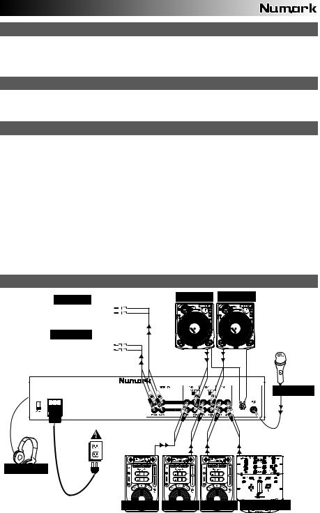
CONNECTION DIAGRAM
CD BURNER |
TURNTABLE |
TURNTABLE |
|
|
|
HOUSE AMP |
|
|
MICROPHONE
HEADPHONES
CD PLAYER CD PLAYER CD PLAYER REMOTE


 MIXER
MIXER
1
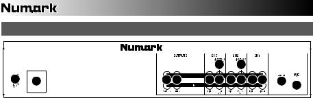
REAR PANEL FEATURES
|
|
|
|
|
5 |
|
5 |
|
|
|
9 |
8 |
7 |
6 |
3 |
4 |
3 |
4 |
3 |
3 |
2 |
|
|
|
|
|
|
|
|
|
|
1 |
1.MIC INPUT – Connect a ¼” microphone to this input. Microphone controls are located on the top panel.
2.GROUNDING TERMINAL – If using phono-level turntables with a grounding wire, be sure to connect the grounding wire to these terminals. If you experience a low “hum” or “buzz”, this could mean that your turntables are not grounded.
Note: Some turntables have the grounding wire built into the RCA connection and, therefore, nothing needs to be connected to the grounding terminal.
3.LINE INPUTS (RCA) – Connect line-level devices, such as CD players, samplers or audio interfaces, to these inputs.
4.AUX | PHONO INPUTS (RCA) – Connect your audio sources to these inputs. These inputs can accept both line and phono-level signals.
5.LINE | PHONO SWITCH – Flip this switch to the appropriate position, depending on the device connected to the PHONO INPUTS. If using phono-level turntables, set this switch to “PHONO” to provide the additional amplification needed for phono-level signals. If using a line-level device, such as a CD player or sampler, set this switch to “LINE.”
6.RECORD OUTPUT (RCA) – Use standard RCA cables to connect this Record output to a recording device, such as a CD recorder or tape deck. The level of this output is based upon pre-master levels.
7.MASTER OUTPUT (RCA) – Use standard RCA cables to connect this Master output to a speaker or amplifier system. The level of this output is controlled by the MASTER FADER on the top panel.
8.POWER IN – Use the included power cable to connect the mixer to a power outlet. While the power is switched off, plug the power supply into the mixer first, then plug the power supply into a power outlet.
9.VOLTAGE SELECTOR – This 2-position switch sets the AC input voltage for the speaker. U.S. users should set this switch to “100-120V” whereas U.K. and most European users will need to set this to “220-240V.”
2
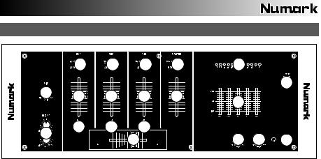
TOP PANEL FEATURES
|
4 |
4 |
4 |
8 |
9 |
|
|
|
|
|
|
|
|
|
14 |
1 |
3 |
3 |
3 |
7 |
|
|
|
|
|
|
|
||||
|
|
|
|
|
10 |
|
|
|
5 |
5 |
5 |
|
|
|
|
2 |
|
|
|
|
|
|
|
|
|
6 |
|
|
11 |
12 |
13 |
1.MIC GAIN – Adjusts the audio level of the microphone signal.
2.MIC TREBLE & BASS – Adjusts the treble (high) and bass (low) frequencies of the audio for both mic inputs.
Tip: If you experience feedback when using a microphone at loud levels, try turning down the high (treble) frequencies.
3.CHANNEL FADER – Adjusts the audio level of the corresponding channel.
4.INPUT SELECTOR – Selects the input source to be routed to the corresponding channel. Input jacks are located on the rear panel.
5.CUE – Sends the pre-fader audio Cue channel for monitoring.
6.CROSSFADER – Blends audio playing between Channels 2 and 3. Sliding this to the left plays Channel 2 and sliding to the right plays Channel 3.
Note: The crossfader is user-replaceable if it should ever wear out. Simply remove the facepanel, then remove the screws holding it in position. Replace the fader with a quality authorized replacement from your local Numark retailer only.
7.MASTER FADER – Adjusts the output volume of the Program mix.
8.STEREO / MONO – Adjusts the Program mix for stereo or mono operation.
9.STEREO LEVEL INDICATOR – Monitors the audio level of the Program mix.
10.GRAPHIC EQUALIZER (EQ) – Adjusts the high, mid-range, and low frequencies of the combined audio output from Channels 1-4. EQ compensates for differences in source material sound quality. The center frequencies of this 5-band graphic equalizer are 63Hz, 250Hz, 1kHz, 4kHz and 16kHz. Faders have a center detent for an accurate "flat” response.
Tips:
Boosting (increasing) the 63Hz band will increase the deep bass tones and “kick drum” sounds, but could cause your amplifiers to “clip” or distort if set too high.
Slightly cutting (decreasing) the 250Hz and 1kHz bands will give the sound some extra clarity.
Boosting the 16kHz band will give the audio a sharper tone.
As a general rule, the less equalization, the better.
11.HEADPHONE MIX – Slide this to mix the Cue channel and Program mix in the headphones. When all the way to the left, only channels routed to the Cue channel will be heard. When all the way to the right, only the Program mix will be heard.
12.HEADPHONE GAIN – Adjusts the volume level of the headphone output.
13.HEADPHONE OUTPUT – Connect your ¼” headphones to this output for cueing and mix monitoring.
14.POWER SWITCH – Turns the mixer on and off. Turn on the mixer after all input devices have been connected and before you turn on amplifiers. Turn off amplifiers before you turn off the mixer.
3

CONTENIDO DE LA CAJA
yC1
yCable de alimentación IEC
yGuía de inicio rápido
yFolleto de información sobre la seguridad y la garantía
REGISTRO
Visite http://www.numark.com y registre su C1. El registro de su producto asegura que podamos mantenerle actualizado con los desarrollos de productos de último momento y brindarle apoyo técnico de categoría mundial en caso de que tenga algún problema.
REGLAS BÁSICAS
1.Asegúrese de que todos los artículos indicados en “Contenido de la caja" estén incluidos en la caja.
2.LEA EL FOLLETO DE INFORMACIÓN SOBRE LA SEGURIDAD Y LA GARANTÍA ANTES DE UTILIZAR EL PRODUCTO.
3.Estudie el diagrama de conexión incluido en esta guía.
4.Coloque el mezclador en una posición adecuada para su funcionamiento.
5.Asegúrese que todos los dispositivos estén apagados y que todos los faders y perillas de ganancia estén en posición «cero».
6.Conecte todas las fuentes de entrada estéreo como se indica en el diagrama.
7.Conecte las salidas estéreo a los amplificadores de potencia, bandejas de cinta magnética y/o otras fuentes de audio.
8.Enchufe todos los dispositivos al suministro de corriente alterna.
9.Encienda todo en el siguiente orden:
yfuentes de entrada de audio (por ejemplo, giradiscos, reproductores de CD, etc.)
yel mezclador
ypor último, cualquier amplificador o dispositivo de salida
10.Al apagar, realice siempre esta operación en sentido inverso:
yapague los amplificadores
yel mezclador
ypor último, cualquier dispositivo de entrada
DIAGRAMA DE CONEXIÓN
GRABADORA DE CD |
GIRADISCOS GIRADISCOS |
AMPLIFICADOR DE AUDITORIO |
MICRÓFONO
AURICULARES
REPRODUCTOR REPRODUCTOR REPRODUCTOR |
MEZCLADOR |
||
DE CD |
DE CD |
DE CD |
REMOTO |
5
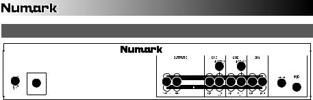
CARACTERÍSTICAS DEL PANEL TRASERO
|
|
|
|
|
5 |
|
5 |
|
|
|
9 |
8 |
7 |
6 |
3 |
4 |
3 |
4 |
3 |
3 |
2 |
|
|
|
|
|
|
|
|
|
|
1 |
1.ENTRADA DE MICRÓFONO – Conecte a esta entrada un micrófono con un cable de ¼”. Los controles de micrófono se encuentran en el panel superior.
2.TERMINAL DE TIERRA – Si usa giradiscos de nivel fonográfico con cable de conexión a tierra, asegúrese de conectar dicho cable a estos terminales. Si se experimenta un zumbido grave, puede significar que sus giradiscos no están conectados a tierra.
Nota: Algunos giradiscos tienen el cable de conexión a tierra incorporado a la conexión RCA y, por lo tanto, no es necesario conectar nada al terminal de tierra.
3.ENTRADAS DE LÍNEA (RCA) – Estas entradas se usan para conectar dispositivos de nivel de línea, tales como reproductores de CD, muestreadores o interfaces de audio.
4.ENTRADAS DE AUX | FONOGRÁFICA (RCA) – Conecte sus fuentes de audio a estas entradas. Estas entradas pueden aceptar señales de nivel de línea y fonográfico.
5.INTERRUPTOR DE ENTRADA DE LÍNEA | FONOGRÁFICA – Coloque este conmutador en la posición apropiada, en función del dispositivo conectado a las entradas LINE | PHONO. Si usa giradiscos de nivel fonográfico, coloque este conmutador en “PHONO” para proporcionar la amplificación adicional necesaria para las señales de este nivel. Si usa un dispositivo de nivel de línea, tal como un reproductor de CD o muestreador, coloque este conmutador en “LINE”.
6.SALIDA PARA GRABACIÓN (RCA) – Use cables RCA estándar para conectar esta salida a un dispositivo de grabación, tal como un grabador de CD o bandeja de cinta. El nivel de esta salida se basa en los niveles pre-master.
7.SALIDA MAESTRA (RCA) – Use cables RCA estándar para conectar esta salida maestra a un sistema de altavoces o amplificador. El nivel de esta salida se controla con la FADER MAESTRO del panel superior.
8.ENTRADA DE ALIMENTACIÓN - Use el cable de alimentación incluido para conectar el mezclador a un tomacorriente alimentado. Con la alimentación eléctrica desconectada, enchufe la fuente de alimentación al mezclador primero, y luego al tomacorriente.
9.SELECTOR DE VOLTAJE – Este conmutador de 2 posiciones establece el voltaje de entrada de CA del altavoz. Los usuarios de EE.UU. deben colocar este conmutador en “100-120V”, mientras que los del Reino Unido y la mayoría de los países europeos deben colocarlo en “220-240V”.
6
 Loading...