


QUICKSTART GUIDE
ENGLISH ( 3 – 6 )
GUÍA DE INICIO RÁPIDO
ESPAÑOL ( 7 – 10 )
GUIDE D'UTILISATION RAPIDE
FRANÇAIS ( 11 – 14 )
GUIDA RAPIDA
ITALIANO ( 15 – 18 )
KURZANLEITUNG
DEUTSCH ( 19 – 22 )

BOX CONTENTS
M6 USB
Power cable
USB cable
Quickstart Guide
Safety & Warranty Information Booklet
REGISTRATION
Please go to http://www.numark.com to register your M6 USB. Registering your product ensures that we can keep you up-to- date with any new product developments and provide you with world-class technical support, should you run into any problems.
GROUND RULES
1.Make sure all items listed in the BOX CONTENTS section are included in the box.
2.READ SAFETY & WARRANTY INFORMATION BOOKLET BEFORE USING THE PRODUCT.
3.Study the connection diagram in this guide.
4.Place mixer in an appropriate position for operation.
5.Make sure all devices are turned off and all faders and gain knobs are set to "zero."
6.Connect all stereo input sources as indicated in the diagram.
7.Connect the stereo outputs to power amplifier(s), tape decks, and/or other audio sources.
8.Plug all devices into AC power.
9.Switch everything on in the following order:
•Audio input sources (i.e. turntables, CD players, etc.)
•Mixer
•Last, any amplifiers or output devices
10.When turning off, always reverse this operation by turning off:
•Amplifiers
•Mixer
•Last, any input devices
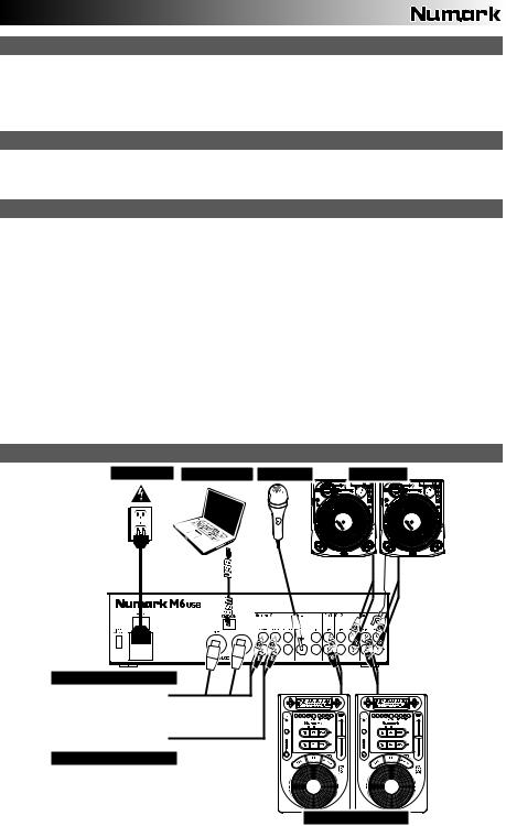
CONNECTION DIAGRAM
POWER |
COMPUTER |
MICROPHONE |
TURNTABLES |
MIXER
HOUSE AMP
BOOTH AMP
CD PLAYERS
3
REAR PANEL FEATURES
|
3 |
|
7 |
|
|
4 |
2 |
1 |
9 |
9 |
101112 |
|
6 6 6 5 6 5 |
|
8 |
|||||
|
|
|
|
|
|
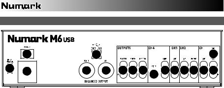
1.POWER IN – Use the included power adapter to connect the mixer to a power outlet. While the power is switched off, plug the power supply into the mixer first, then plug the power supply into a power outlet.
2.VOLTAGE SELECTOR – This 2-position switch sets the AC input voltage for the speaker. U.S. users should set this switch to "100-120V" whereas U.K. and most European users will need to set this to "220-240V".
3.POWER SWITCH – Turns the mixer on and off. Turn on the mixer after all input devices have been connected and before you turn on amplifiers. Turn off amplifiers before you turn off the mixer.
4.GROUNDING TERMINAL – If using phono-level turntables with a grounding wire, connect the grounding wire to these terminals. If you experience a low "hum" or "buzz", this could mean that your turntables are not grounded.
Note: Some turntables have a grounding wire built into the RCA connection and, therefore, nothing needs to be connected to the grounding terminal.
5.PHONO INPUTS (RCA) – Connect phono-level devices, such as turntables, to these inputs.
6.LINE INPUTS (RCA) – Connect line-level devices, such as CD players, samplers or audio interfaces, to these inputs.
7.CH3 USB – Outputs the Record mix to your computer for recording purposes or sends incoming audio from your computer to mixer's Channel 3.
8.MIC 2 INPUT – If you would like to use an additional 1/4" microphone on Channel 4, connect it to this input. To route the microphone signal to the mix, you will need to flip the Channel 4 Input Selector switch, located on the top panel, to "Mic".
9.MASTER OUTPUT (BALANCED XLR) – Connect this low-impedance XLR output to a speaker or amplifier system. The level of this output is controlled with the MASTER FADER on the top panel.
10.MASTER OUTPUT (RCA) – Use standard RCA cables to connect this output to a speaker or amplifier system. The level of this output is controlled by the MASTER FADER on the top panel.
11.BOOTH OUTPUT (RCA) – Use standard RCA cables to connect this output to a booth monitoring system. The level of this output is controlled by the Booth knob on the top panel.
12.RECORD OUTPUT (RCA) – Use standard RCA cables to connect this output to a recording device, such as a CD recorder or tape deck. The level of this output is based upon pre-master levels.
4
TOP PANEL FEATURES
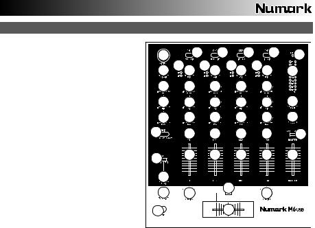
1.POWER LED – Illuminates when the
|
mixer is on. |
|
|
|
|
|
|
17 |
|
|
2 |
|
2 |
2 |
|
2 |
1 |
|
2. |
INPUT SELECTOR – Selects |
the input |
|
|
|
|
|
|
|
|
||||||||
|
3 |
|
3 |
|
3 |
|
3 |
|
|
|||||||||
|
source to be routed to the corresponding |
18 |
4 |
4 |
4 |
4 |
24 |
|||||||||||
|
|
|
|
|
||||||||||||||
|
channel. Input jacks are located on the |
|
|
|
|
|||||||||||||
|
|
|
|
|
|
|
|
|
|
|
||||||||
|
rear panel. |
|
|
|
|
|
|
19 |
|
5 |
|
5 |
|
5 |
|
5 |
|
|
3. |
CHANNEL |
LEVEL |
INDICATOR |
– |
|
|
|
|
|
|||||||||
|
|
|
|
|
|
|
|
|
|
|||||||||
|
Displays |
the |
audio |
level |
of |
the |
20 |
|
6 |
|
6 |
|
6 |
|
6 |
27 |
||
|
corresponding channel. |
|
|
|
|
|
|
|
||||||||||
|
|
|
|
|
|
|
|
|
|
|
|
|
|
|||||
4. |
CHANNEL GAIN – Adjusts the channel's |
21 |
|
7 |
|
7 |
|
7 |
|
7 |
26 |
|||||||
|
pre-fader and pre-EQ gain level. |
|
|
|
|
|
|
|||||||||||
|
|
|
|
|
|
|
|
|
|
|
|
|
||||||
5. |
CHANNEL TREBLE – Adjusts the |
high |
22 |
|
8 |
|
8 |
|
8 |
|
8 |
25 |
||||||
|
(treble) frequencies of the corresponding |
|
|
|
|
|
||||||||||||
|
|
|
|
|
|
|
|
|
|
|
||||||||
|
channel. |
|
|
|
|
|
|
|
|
|
|
|
|
|
|
|
|
|
6. |
CHANNEL MID – Adjusts the mid-range |
15 |
|
9 |
|
9 |
|
9 |
|
9 |
23 |
|||||||
|
frequencies |
|
of |
the |
corresponding |
|
|
|
|
|
|
|
|
|
||||
|
|
|
|
|
|
|
|
|
|
|
|
|||||||
|
channel. |
|
|
|
|
|
|
|
|
|
|
|
|
|
|
|
|
|
7. |
CHANNEL |
BASS |
– |
Adjusts |
the |
low |
16 |
|
|
|
|
|
|
|
|
|
||
|
(bass) frequencies of the corresponding |
|
|
|
|
|
12 |
|
|
|
|
|||||||
|
channel. |
|
|
|
|
|
|
|
14 |
|
10 |
|
|
|
|
10 |
|
|
|
|
|
|
|
|
|
|
|
|
|
|
|
|
|
||||
8. |
CHANNEL CUE – Sends pre-fader audio |
|
|
|
|
|
|
|
|
|
|
|||||||
|
to the |
Cue |
Channel |
for headphone |
13 |
|
|
|
|
11 |
|
|
|
|
||||
|
monitoring. |
|
|
|
|
|
|
|
|
|
|
|
|
|
|
|
|
|
9.CHANNEL FADER – Adjusts the audio level on the corresponding channel.
10.CF ASSIGN – Selects which input channel will be heard when the crossfader is moved towards this knob. All channels not assigned will remain active.
11.CROSSFADER – Blends audio between the channels assigned to the left and right side of the crossfader.
Note: The crossfader is user-replaceable if it should ever wear out. Simply remove the facepanel, then remove the screws holding it in position. Replace the fader with a quality authorized replacement from your local Numark retailer only.
12.CF SLOPE – Adjusts the slope of the crossfader curve. Flip switch to the left for a smooth fade (mixing) or to the right for a sharp cut (scratching).
13.HEADPHONES – Connect your 1/4" headphones to this output for cueing and mix monitoring.
14.CUE GAIN – Adjusts the audio level of the Cue channel.
15.CUE MIX / SPLIT – When this switch is in the SPLIT position, the headphone audio will be "split" such that all channels sent to CUE are mixed to mono and applied to the left headphone channel and the Program mix is mixed to mono and applied to the right channel. When the switch is in the MIX position, Cue and Program audio will be "blended" together.
16.CUE MIX – Turn to mix between Cue and Program in the Headphone channel. When all the way to the left, only channels routed to CUE will be heard. When all the way right, only the Program mix will be heard.
17.MIC 1 INPUT – Connect a microphone to this input with an XLR cable.
18.MIC GAIN – Adjusts the audio level of the microphone signal.
19.MIC TREBLE – Adjusts the high (treble) frequencies of the microphone channel.
Tip: If you experience feedback when using a microphone at loud levels, try turning down the high frequencies.
20.MIC MID – Adjusts the mid-range frequencies of the microphone channel.
21.MIC BASS – Adjusts the low (bass) frequencies of the microphone channel.
22.MIC ON / OFF – Turns the microphone input on or off. "TALKOVER" reduces the combined levels of Channels 1-4 to -12dB (an appropriate "talkover" level).
23.MASTER FADER – Adjusts the output volume of the Program mix.
24.STEREO LEVEL INDICATOR – Displays the audio level of the Program mix.
25.MONO / STEREO – Adjusts the Program mix for stereo or mono operation.
26.BALANCE – Adjusts the balance of right to left audio in all outputs (MASTER, RECORD, and ZONE OUTPUTS).
27.BOOTH VOLUME – Adjusts the Booth output level.
5

USB OPERATION
The M6 USB is equipped with a USB port which allows you to play content from your computer through the mixer, or record audio from the mixer directly into your favorite software application. The USB interface on your mixer works with your computer just like a standard USB sound card. In addition, the USB interface is class-compliant, so there are no special drivers or software to install; simply connect a USB cable from the USB port to your computer and you are ready to go!
AUDIO SETUP
The M6 USB is a class-compliant device that can be used with any digital audio workstation or recording software that supports USB audio. To enable your M6 USB to send and receive audio to and from your computer, follow the instructions below for your computer's operating system:
WINDOWS 7:
1.Use the included cable to connect the M6 USB to your computer.
2. |
Go to Start Menu Control Panel Hardware and |
* If you have other USB audio devices |
|||
connected to your computer, which may |
|||||
|
Sound Sound. |
||||
|
have identical names, you may need to |
||||
3. |
Click the Playback tab and select USB Audio Codec* |
||||
try selecting each one until the M6 USB |
|||||
|
as the default device. |
||||
|
is recognized. |
|
|||
4. |
Click the Recording tab and select USB Audio Codec* |
|
|||
|
|
|
|||
|
as the default device. |
|
|
|
|
5. |
Click Properties in the lower right-hand corner. |
If |
you experience too |
much latency |
|
6. |
In the new window, click the Advanced tab and select 2- |
||||
|
channel, 16-bit, 44100 Hz (CD Quality) as the default |
after adjusting your software latency |
|||
|
settings, we recommend the free |
||||
|
format. |
||||
|
ASIO4ALL (Audio Stream Input/Output) |
||||
7. |
Uncheck both boxes under Exclusive Mode. |
||||
driver for PC at www.asio4all.com. |
|||||
8. |
Click the Levels tab and set the slider to "4." |
||||
ASIO drivers generally perform better |
|||||
9. |
Click OK to close the Properties window. |
||||
and with lower latency since they create |
|||||
10. |
Click OK to close the Sound control panel. |
||||
a |
more efficient |
communication |
|||
|
|
||||
WINDOWS VISTA: |
between audio devices and software. |
|
1.Use the included cable to connect the M6 USB to your computer.
2. Go to Start Menu Control Panel Sound. (If you don't see Sound, select Switch to Classic View, and the Sound Control Panel should become available.)
3.Click the Playback tab and select USB Audio Codec* as the default device.
4.Click the Recording tab and select USB Audio Codec* as the default device.
5.Click Properties in the lower right-hand corner.
6.In the new window, click the Advanced tab and select 2-channel, 16-bit, 44100 Hz (CD Quality) as the default format.
7.Uncheck both boxes under Exclusive Mode.
8.Click OK to close the Properties window.
9.Click OK to close the Sound control panel.
WINDOWS XP:
1.Use the included cable to connect the M6 USB to your computer.
2. Go to Start Menu Control Panel Sounds and Audio Devices.
3.Click the Audio tab.
4.Under Sound Playback and Sound Recording, select USB Audio Codec* as the default device.
5.Click OK.
MAC:
1.Use the included cable to connect the M6 USB to your computer.
2. |
Go to Applications Utilities Audio MIDI Setup. |
3.In the Audio Devices tab under System Settings, select USB Audio Codec* as your Default Input and Default Output.
4.Close the window.
6
CONTENIDO DE LA CAJA
M6 USB
Cable de alimentación
Cable USB
Guía de inicio rápido
Folleto de información sobre la seguridad y la garantía
REGISTRO
Visite http://www.numark.com y registre su M6 USB. El registro de su producto asegura que podamos mantenerle actualizado con los nuevos desarrollos de productos y brindarle apoyo técnico de categoría mundial en caso de que tenga algún problema.
REGLAS BÁSICAS
1.Asegúrese de que todos los artículos indicados en "Contenido de la caja" estén incluidos en la caja.
2.LEA EL FOLLETO DE INFORMACIÓN SOBRE LA SEGURIDAD Y LA GARANTÍA ANTES DE UTILIZAR EL PRODUCTO.
3.Estudie el diagrama de conexión incluido en esta guía.
4.Coloque el mezclador en una posición adecuada para su funcionamiento.
5.Asegúrese que todos los dispositivos estén apagados y que todos los faders y perillas de ganancia estén en posición «cero».
6.Conecte todas las fuentes de entrada estéreo como se indica en el diagrama.
7.Conecte las salidas estéreo a los amplificadores de potencia, bandejas de cinta magnética y/o otras fuentes de audio.
8.Enchufe todos los dispositivos al suministro de corriente alterna.
9.Encienda todo en el siguiente orden:
y fuentes de entrada de audio (por ejemplo, giradiscos, reproductores de CD, etc.) y el mezclador
y por último, cualquier amplificador o dispositivo de salida
10.Al apagar, realice siempre esta operación en sentido inverso: y apague los amplificadores
y el mezclador
y por último, cualquier dispositivo de entrada
DIAGRAMA DE CONEXIÓN
ALIMENTACIÓN COMPUTADORA MICRÓFONO |
GIRADISCOS |
MEZCLADOR |
AMPLIFICADOR DE AUDITORIO |
AMPLIFICADOR DE CABINA
REPRODUCTORS DE CD
7
CARACTERÍSTICAS DEL PANEL TRASERO
|
3 |
|
7 |
|
|
4 |
2 |
1 |
9 |
9 |
101112 |
|
6 6 6 5 6 5 |
|
8 |
|||||
|
|
|
|
|
|
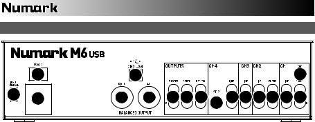
1.ENTRADA DE ALIMENTACIÓN – Use el adaptador de alimentación incluido para conectar el mezclador a un tomacorriente alimentado. Mientras está desconectada la alimentación eléctrica, enchufe la fuente de alimentación al mezclador primero, y luego al tomacorriente.
2.SELECTOR DE VOLTAJE – Este conmutador de 2 posiciones establece el voltaje de entrada de CA del altavoz. Los usuarios de EE.UU. deben colocar este conmutador en "100-120V", mientras que los del Reino Unido y la mayoría de los países europeos deben colocarlo en "220-240V".
3.INTERRUPTOR DE ENCENDIDO – Enciende y apaga el mezclador. Encienda el mezclador después de desconectar todos los dispositivos de entrada y antes de encender los amplificadores. Apague los amplificadores antes de apagar el mezclador.
4.ENTRADAS DE LÍNEA (RCA) – Estas entradas se usan para conectar dispositivos de nivel de línea, tales como reproductores de CD, muestreadores o interfaces de audio.
5.ENTRADAS FONOGRÁFICAS (RCA) – Estas entradas se usan para conectar dispositivos de nivel fonográfico, como giradiscos.
6.TERMINAL DE TIERRA – Si usa giradiscos de nivel fonográfico con cable de conexión a tierra, asegúrese de conectar dicho cable a estos terminales. Si se experimenta un zumbido grave, puede significar que sus giradiscos no están conectados a tierra.
Nota: Algunos giradiscos tienen el cable de conexión a tierra incorporado a la conexión RCA y, por lo tanto, no es necesario conectar nada al terminal de tierra.
7.CH3 USB – Envía la mezcla para grabar a su computadora a los fines de su grabación o envía el audio entrante de su computadora al canal 3 del mezclador.
8.ENTRADA DE MICRÓFONO 2 – Si desea usar un micrófono de 1/4" adicional en el canal 4, conéctelo a esta entrada. Para aplicar la señal de micrófono a la mezcla, debe colocar el conmutador selector de entrada del canal 4, ubicado en el panel superior, en "Mic".
9.SALIDA MAESTRA (XLR) – Esta salida XLR de baja impedancia sirve para conectar a un sistema de altavoces o amplificador. El nivel de esta salida se controla con el FADER MAESTRO del panel superior.
10.SALIDA MAESTRA (RCA) – Use cables RCA estándar para conectar esta salida maestra a un sistema de altavoces o amplificador. El nivel de esta salida se controla con el FADER MAESTRO del panel superior.
11.SALIDA PARA CABINA (RCA) – Use cables RCA estándar para conectar esta salida a un sistema de monitoreo de cabina. El nivel de esta salida se controla con la perilla BOOTH del panel superior.
12.SALIDA PARA GRABACIÓN (RCA) – Use cables RCA estándar para conectar esta salida a un dispositivo de grabación, tal como un grabador de CD o bandeja de cinta. El nivel de esta salida se basa en los niveles pre-master.
8
 Loading...