

Page 1

AIREGARD™ ES Energy Saver Horizontal Laminar Flow
Clean Workstation
Model NU-240
Bench Top Model
Operation and Maintenance Manual
August, 2019
Revision 5
Series 1
(115VAC ONLY)
Manufactured By:
NuAire, Inc.
2100 Fernbrook Lane
Plymouth, MN 55447
Toll-Free: 1-800-328-3352
In Minnesota: (763)-553-1270
Fax: (763)-553-0459
OM0267
Rev 5 August/2019 Page 1 of 46
Page 2

AIREGARD™ ES Energy Saver Horizontal Laminar Flow
Clean Workstation
Model NU-240
Bench Top Model
Operation and Maintenance Manual
Table of Contents
Section No. 1 .............................................................................. General Description
Section No. 2 .............................................................................. Models & Features
Section No. 3 .............................................................................. Shipments
Section No. 4 .............................................................................. Installation Instructions
4.1 ...................................................................................... Location
4.2 ...................................................................................... Set-up Instructions
4.3 ...................................................................................... Certification Testing Methods and Equipment
Section No. 5 .............................................................................. Operating the Laminar Flow Clean Workstation
5.1 ...................................................................................... Operator Controls & Indicators
5.2 ...................................................................................... Operating Guidelines
5.3 ...................................................................................... Ergonomics
5.4 ...................................................................................... Cleaning Procedures
Section No. 6 .............................................................................. General Maintenance
6.1 ...................................................................................... Fluorescent Lamp Bulb Replacement
6.2 ...................................................................................... HEPA Filter Replacement
6.3 ...................................................................................... Prefilter Replacement
Section No. 7 .............................................................................. Error Indicators and Troubleshooting
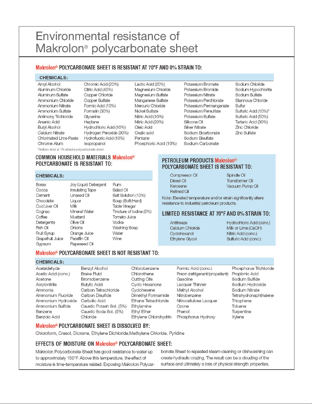
Section No. 8 .............................................................................. Polycarbonate Material Compatibility
Section No. 9 .............................................................................. Remote Contacts
Section No. 10 ............................................................................ Electrical/Environmental Requirements
Section No. 11 ............................................................................ Disposal and Recycle
Insert .......................................................................................... Replacement Parts List, Warranty
Manual Drawings
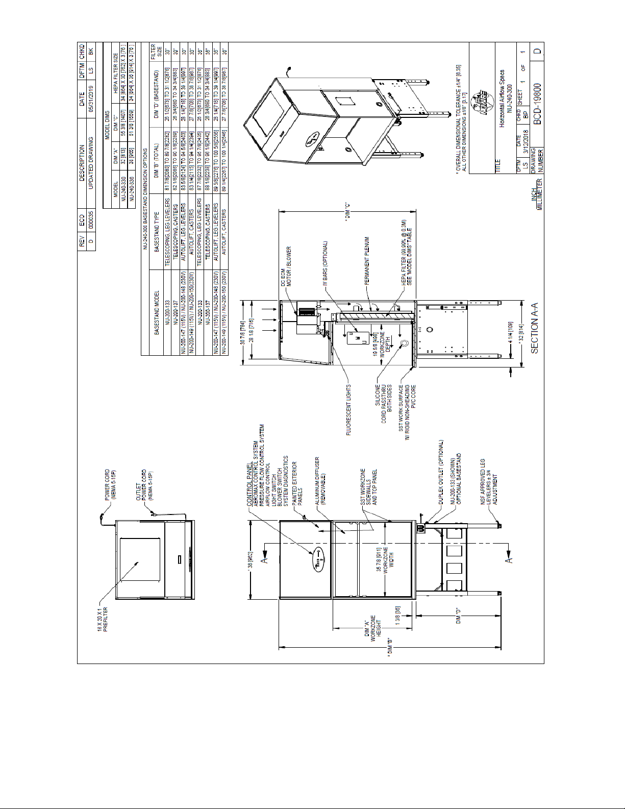
BCD-19800..........................................................Specification Drawing NU-240-300
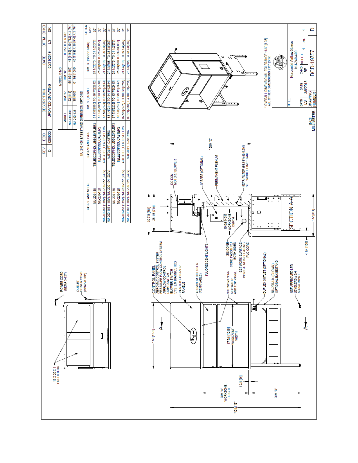
BCD-19757..........................................................Specification Drawing NU-240-400
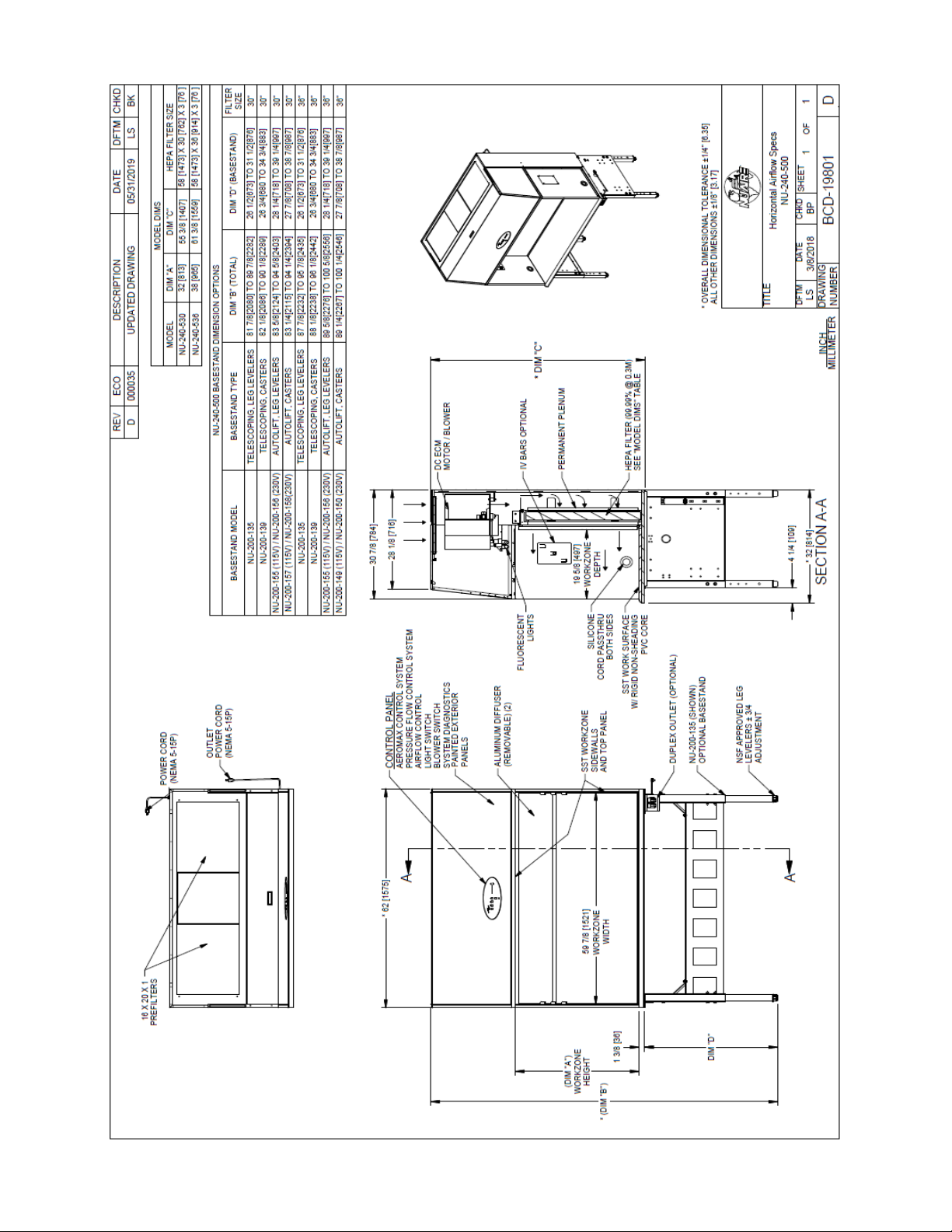
BCD-19801..........................................................Specification Drawing NU-240-500
BCD-19666..........................................................Specification Drawing NU-240-600
Assembly Drawings
ACD-06899..........................................................Blower Brace Removal
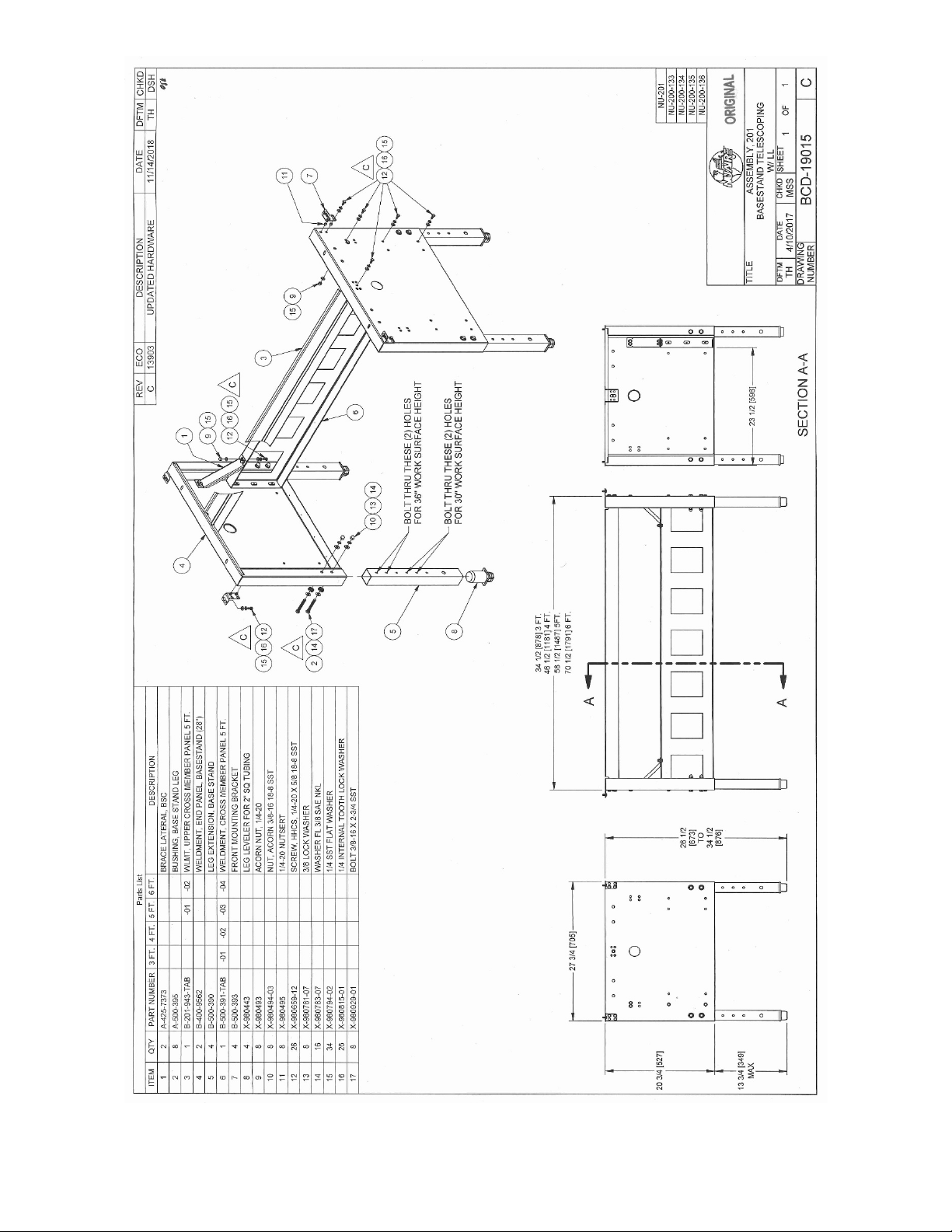
BCD-19015..........................................................Base Stand Telescoping with Leg Levelers
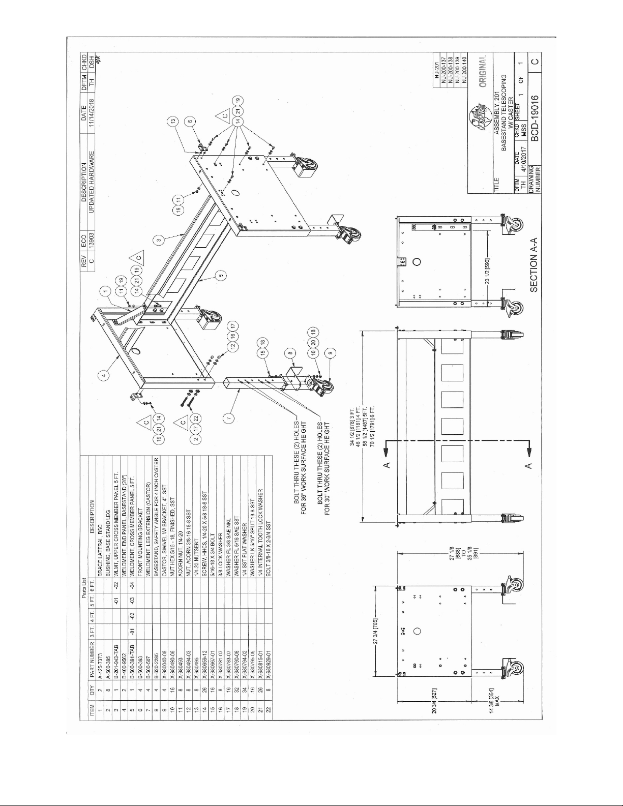
BCD-19016..........................................................Base Stand Telescoping with Caster
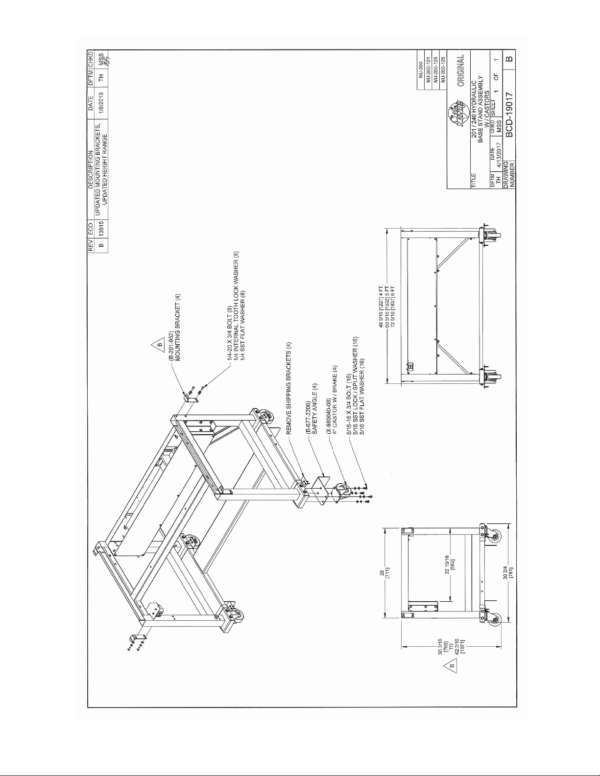
BCD-19017..........................................................Hydraulic Base Stand with Castors
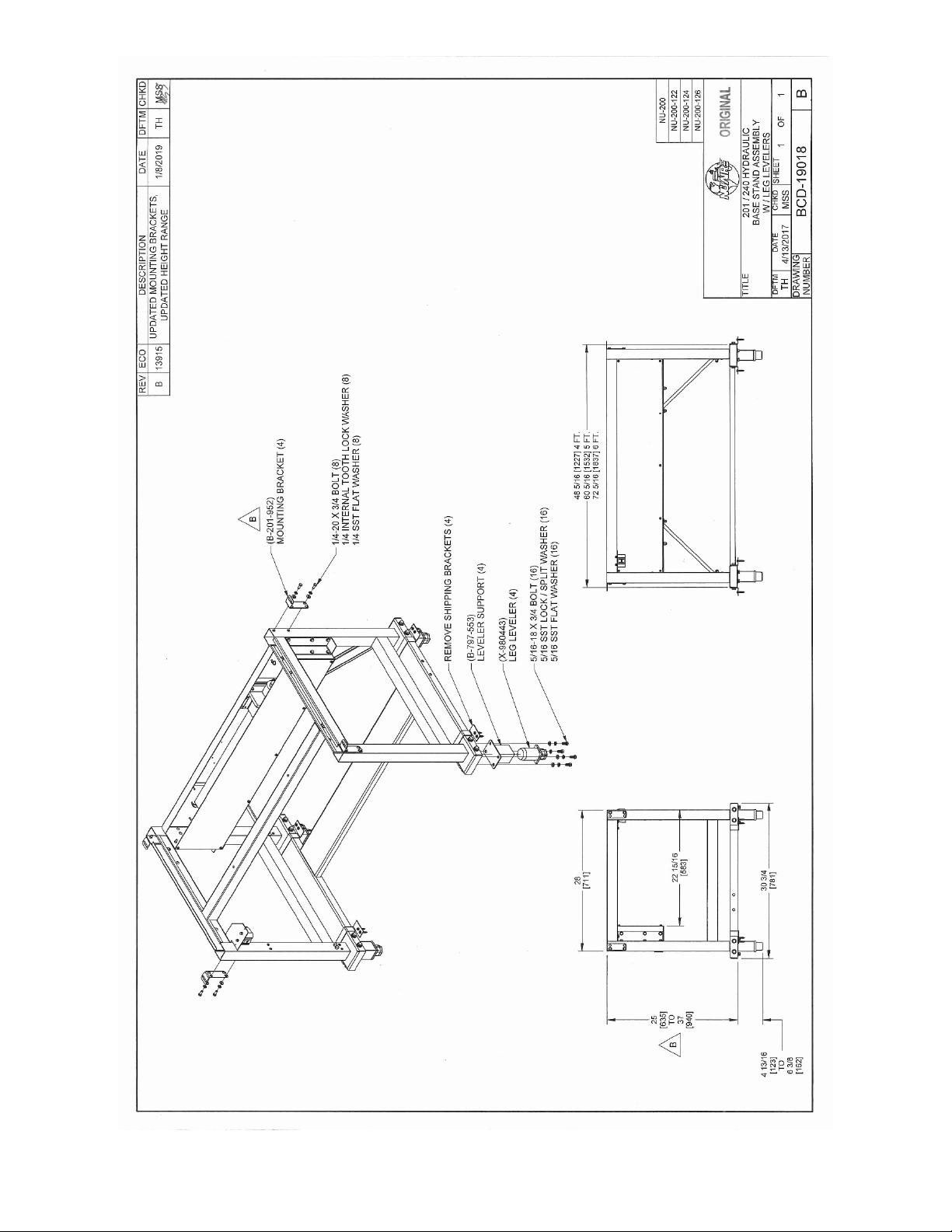
BCD-19018..........................................................Hydraulic Base Stand with Leg Levelers
BCD-16521..........................................................AEROMAX™ Front Panel
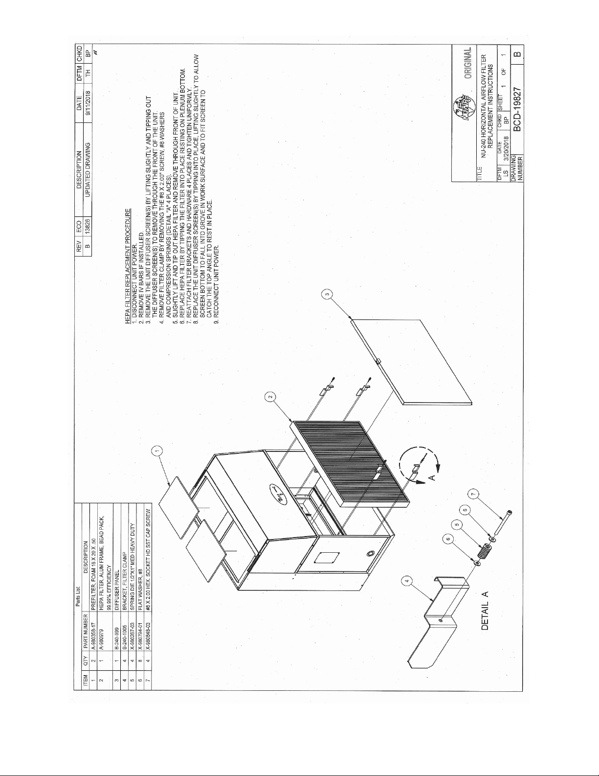
BCD-19827..........................................................Horizontal Airflow Filter Replacement
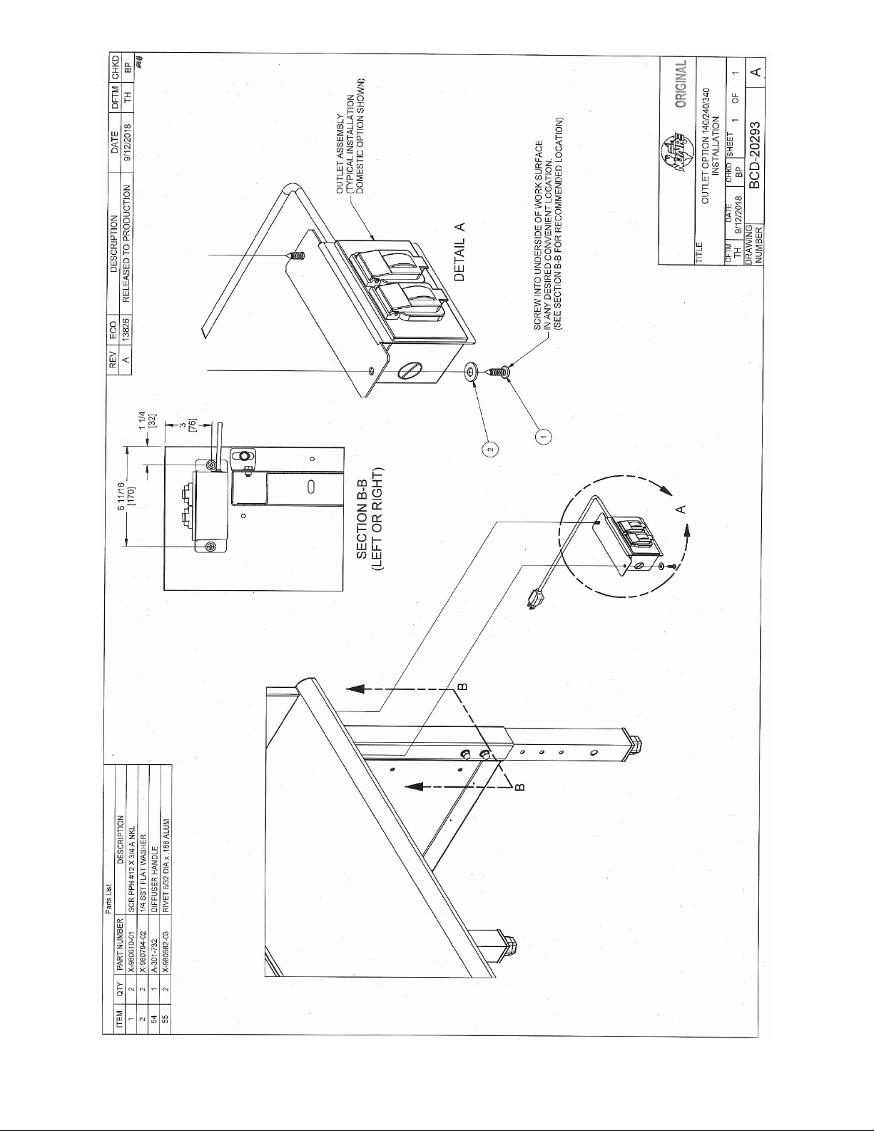
BCD-20293..........................................................Outlet option Instruction
Electrical Schematics
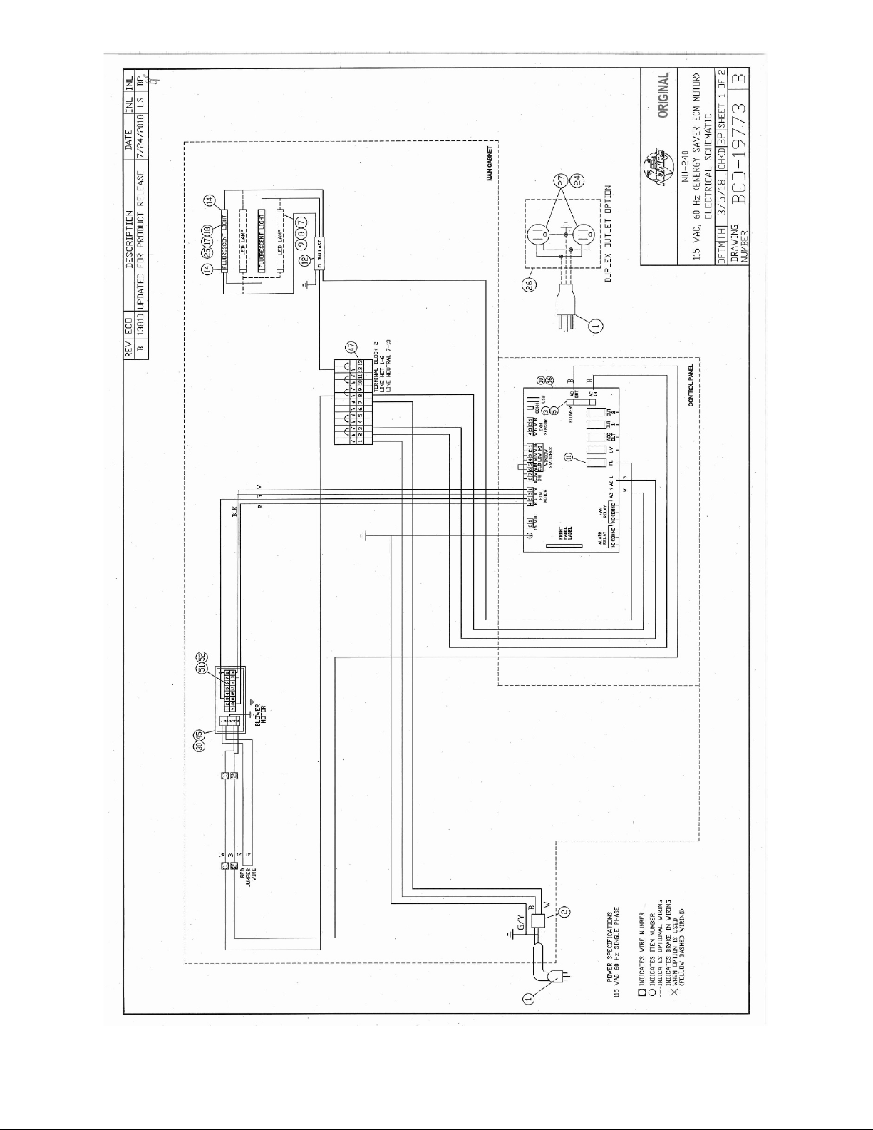
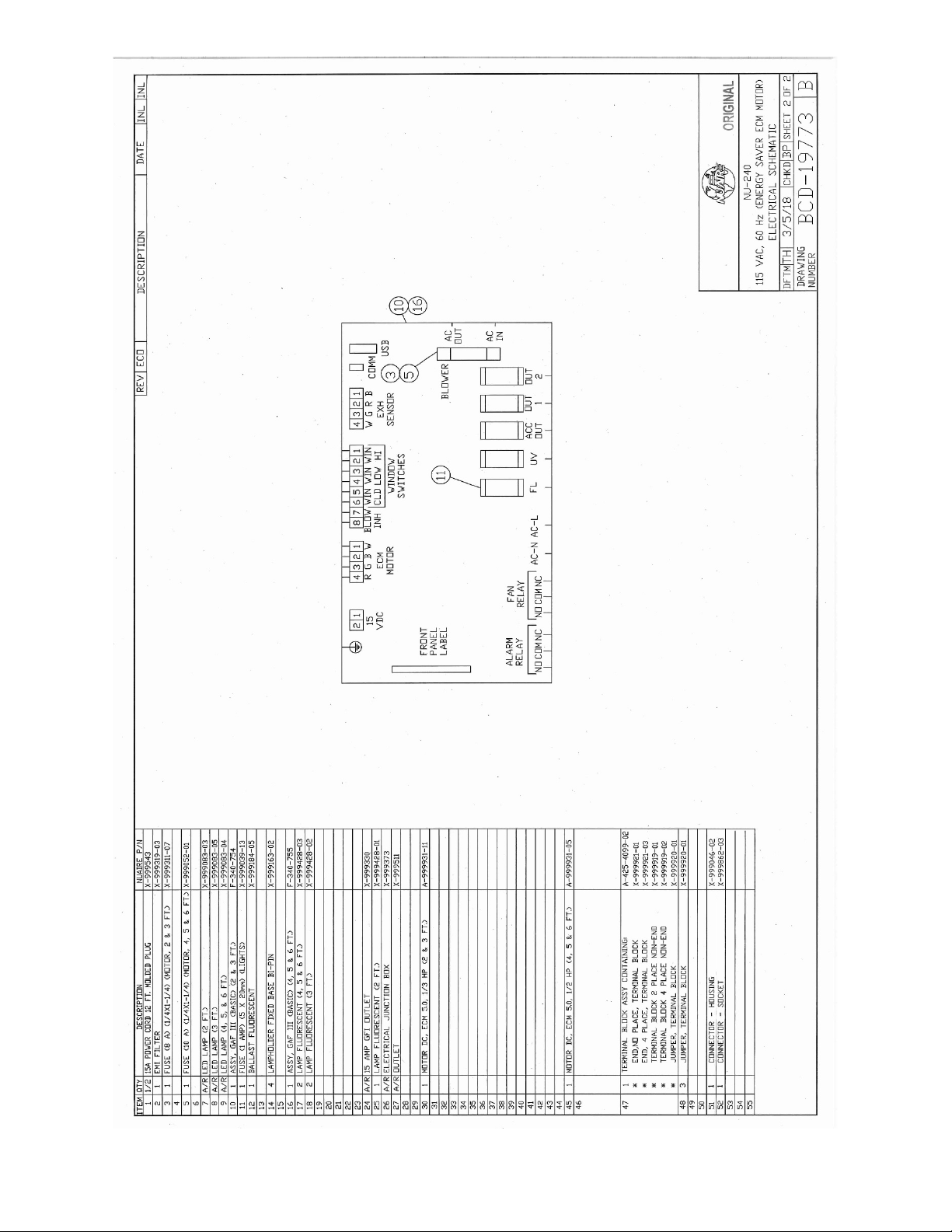
BCD-19773..........................................................Electrical Schematic 115V
OM0267 Page 2 of 46
Rev 5 August/2019
Page 3

1.0 General Description
NuAire AIREGARD™ Horizontal Laminar Flow Clean Workstations utilize the newest technologies in laminar airflow design,
materials and manufacturing processes. The clean workstation can be used where clean airflow per ISO 14644-1 is
required for the preparation of injectable drugs, IV solutions, tissue culture, optics, microelectronics, etc. The clean bench
should not be used for any work that involves biological agents assigned a level of Risk 1 through 4 as classified by the
Centers for Disease Control (CDC), Atlanta, Georgia, since the horizontal flow offers no personnel protection against these
agents. The clean bench should only be used to protect the product from contamination. The clean bench is optionally
available with a base stand, placing the work surface at 30” (762mm) or 36” (914mm). A significant number of design
innovations give the NuAire Laminar flow equipment superior performance qualities in airflow, lighting, noise levels and
vibration.
AIREGARD™ ES Energy Saver Horizontal Laminar Flow
Clean Workstation
Model NU-240
Manufactured By:
NuAire, Inc.,
Plymouth, Minnesota
OM0267 Page 3 of 46
Rev 5 August/2019
Page 4
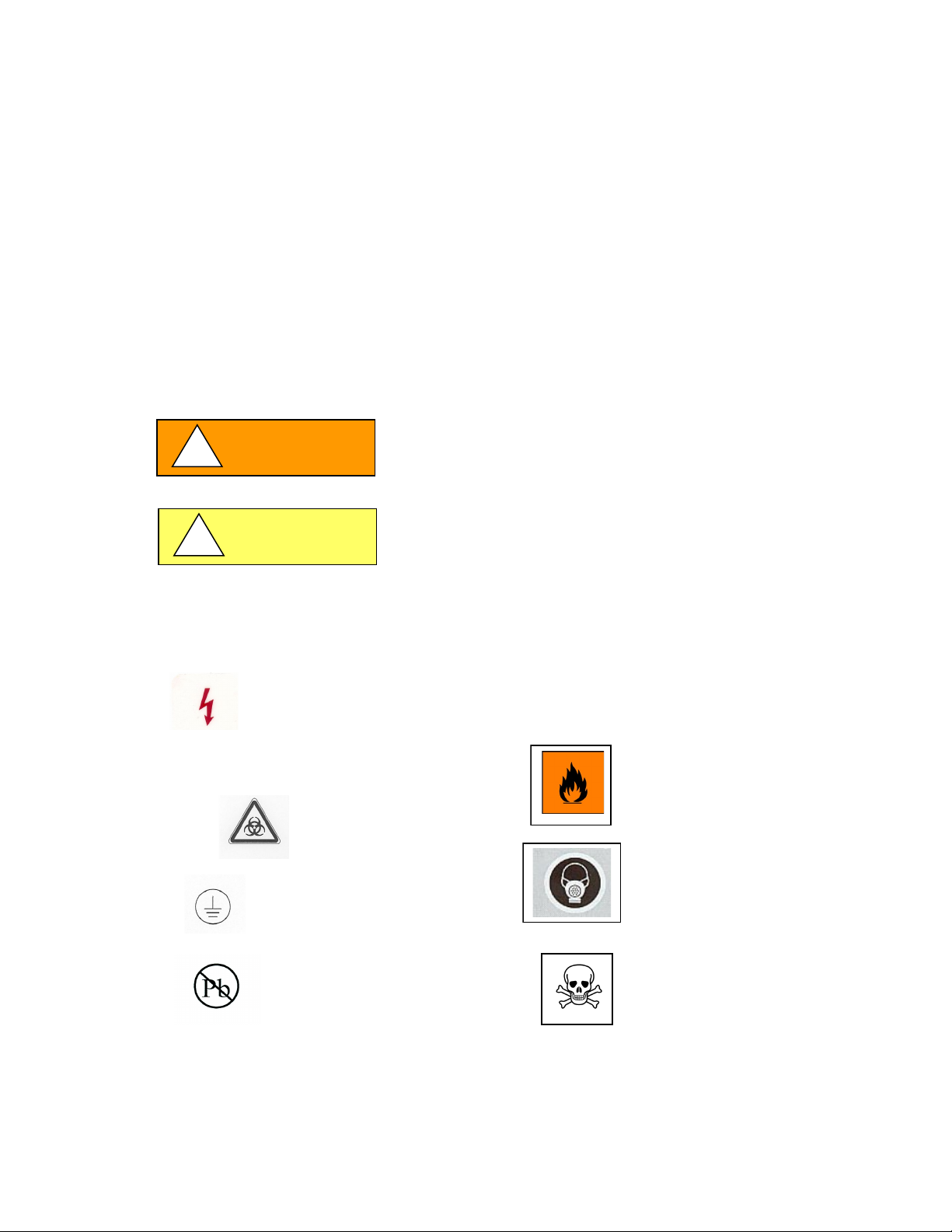
1.1 Safety Instructions
NOTE:
CAUTION used without the safety alert symbol
not avoided, may result in property damage.
Potential electrical hazard, only qualified person
to access.
Used for important information.
Biohazard
Ground, Earth
CAUTION:
Lead Free
Chemical Hazard
Flammable Hazard
Hazardous Gases! Personal
Safety alert symbol indicates a potentially hazardous
of serious injury.
Safety alert symbol indicates a potentially hazardous
moderate injury.
WARNING
!
CAUTION
!
These safety instructions describe the safety features of the AIREGARD™ Horizontal Laminar Flow Clean Workstation model
NU-240. The workstation has been manufactured using the latest technological developments and has been thoroughly
tested before delivery. It may, however, present potential hazards if it is not used according to the intended purpose or
outside of operating parameters. Therefore, the following procedures must always be observed:
• The workstation must be operated only by trained and authorized personnel.
• For any operation of this unit, the operator must prepare clear and concise written instructions for operating and
cleaning, utilizing applicable safety data sheets, plant hygiene guidelines, and technical regulations, in particular.
o which decontamination measures are to be applied for the workstation and accessories,
o which measures are to be taken in the case of an accident.
• Repairs to the device must be carried out only by trained and authorized expert personnel.
• Keep these operating instructions close to the unit so that safety instructions and important information are
always accessible.
• Should you encounter problems that are not detailed adequately in the operating instructions, please contact your
NuAire Representative of NuAire technical Services.
1.2 Explanation of Symbols
indicates a potentially hazardous situation which, if
situation which, if not avoided, could result in death
situation which, if not avoided, may result in minor or
OM0267 Page 4 of 46
Rev 5 August/2019
Protection Equipment Required.
Page 5

2.0 Models and Features
Model Number
NU-240-330
NU-240-336
NU-240-430
NU-240-436
NU-240-530
NU-240-536
NU-240-630
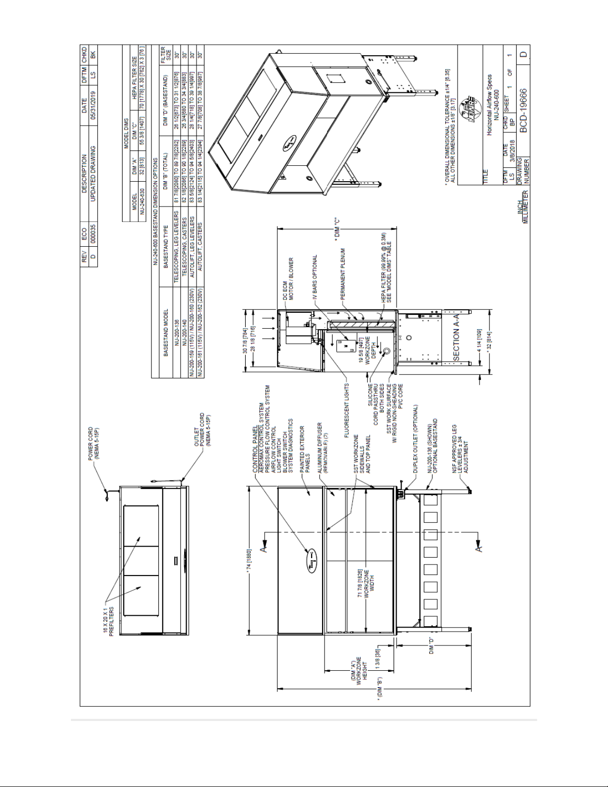
NuAire's Model Number NU-240 designates the basic design series of AIREGARD™ Horizontal Laminar Flow Clean
Workstation with the blower/motor located above the work surface (i.e. bench series). Model numbers are shown below.
OM0267 Page 5 of 46
Rev 5 August/2019
Page 6
OM0267 Page 6 of 46
Rev 5 August/2019
Page 7
OM0267 Page 7 of 46
Rev 5 August/2019
Page 8
OM0267 Page 8 of 46
Rev 5 August/2019
Page 9
OM0267 Page 9 of 46
Rev 5 August/2019
Page 10

3.0 Shipments
NuAire takes every reasonable precaution to insure that your AIREGARD™ Clean Workstation arrives without damage.
Motor carriers are carefully selected and shipping cartons have been specially designed to insure your purchase. However,
damage can occur in any shipment and the following outlines the steps you should take on receipt of a NuAire AIREGARD™
Clean Workstation to be sure that if damage has occurred, the proper claims and actions are taken immediately.
3.1 Damaged Shipments
3.1.1 Terms are factory, unless stated otherwise. Therefore, it is important to check each shipment before acceptance.
3.1.2 If there is visible damage, the material can be accepted after the driver makes a notation on the consignee's copy
of the freight bill. Then an inspection must be made to verify the claim against the carrier. This inspection is the
basis of your filing the claim against the carrier.
3.1.3 If concealed damage is found, it is absolutely necessary to NOTIFY THE FREIGHT AGENT AT ONCE and request an
inspection. Without this inspection, the transportation company may not accept a claim for loss or damage. If the
carrier will not perform the inspection, an affidavit must be prepared stating that he was contacted on a certain
date and that he failed to comply with the request. This, along with other papers in the customer's possession will
support the claim.
OM0267 Page 10 of 46
Rev 5 August/2019
Page 11
4.0 Installation Instructions
4.1 Location
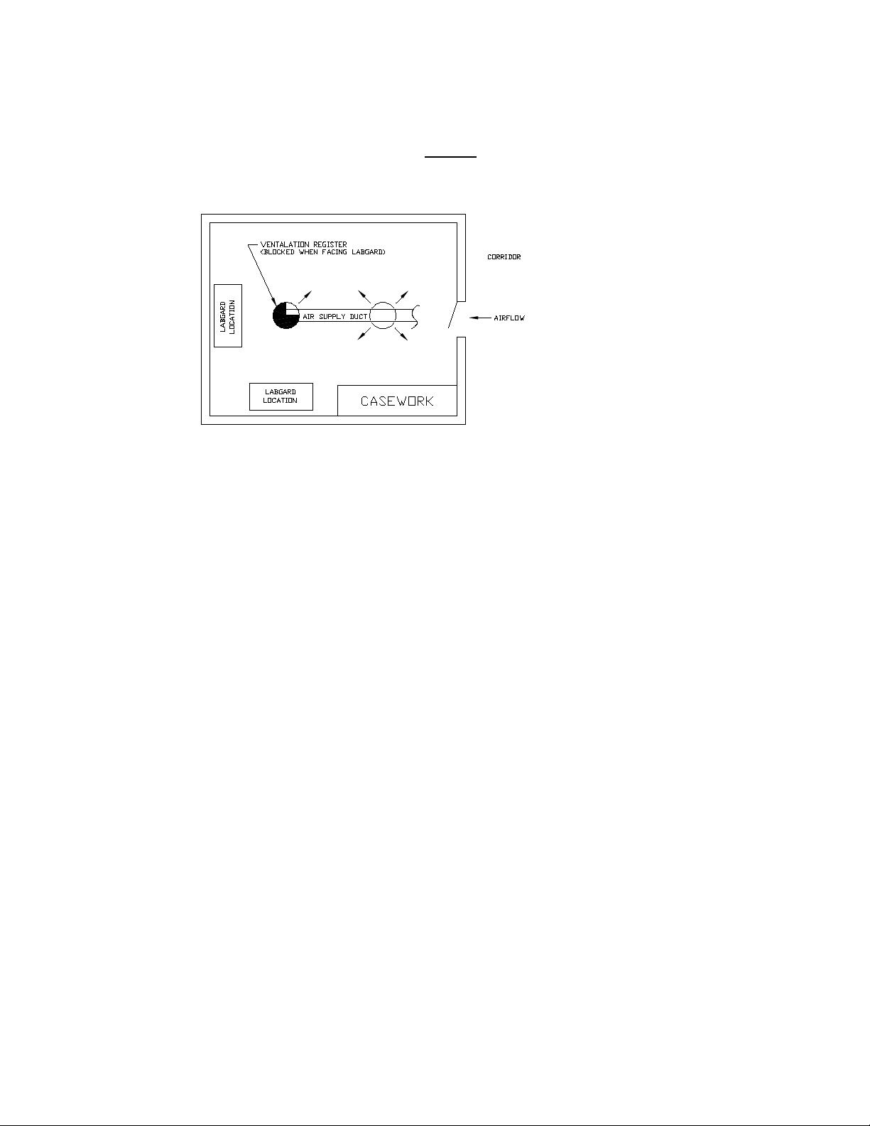
Within the laboratory, pharmacy, production area, etc., the ideal location for the clean workstation is away from personnel
traffic lanes, air vents (in or out), doors and/or other source of disruptive air currents. If drafts or other disruptive air
currents exceed the face velocity of the HEPA filter, the potential exists for contaminated air to enter the work area of the
workstation. Please note, however, that the work area has been constructed to minimize the effect of air currents by
providing sidewalls that are an extension of the HEPA filter flow area.
Where space permits, a clean six (6) inch (152mm) area should be permitted on each side of the workstation for
maintenance purposes. The electrical outlet into which the workstation is connected should be readily accessible.
The workstation shall be positioned as not to obstruct the power supply outlet or the circuit breaker distribution panel.
4.2 Set-Up Instructions
Remove outer shipping protection (carton or crating). If the workstation is fastened to a base skid, it is usually the best
procedure to leave the skid in place until the workstation is located in its approximate position to facilitate ease in handling.
It can then be removed from the skid by removing the four bolts holding the workstation to the skid.
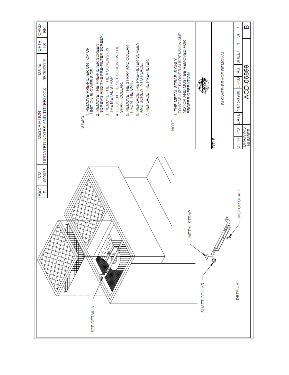
4.2.1 Motor Shipping Bracket
The motor is securely fastened to the workstation during shipment to prevent damage to the blower housing
mounting brackets. The procedure for removing the motor shipping bracket is shown in Drawing ACD-06899.
4.2.2 Base Stand Assembly
The base stand is shipped K.D. in a separate carton and is assembled per the Drawing accompanied with the unit.
With a forklift or other suitable lifting device, lift the NU-240 between the top of the skid and the bottom of the
workstation, slightly off of the floor and remove the four bolts holding the skid to the workstation (one in each
corner). Now lift the workstation on top of the base and bolt the base stand to the workstation using four 4/20 x
¾” (18mm) bolts and washers provided. Place the workstation in its desired location.
OM0267 Page 11 of 46
Rev 5 August/2019
Page 12
4.2.3 Gas Service
CAUTION
!
CAUTION
!
NuAire doesn't recommend the use of natural gas within the clean bench, but if gas service is determined to be
necessary for the application by the appropriate safety personnel, appropriate safety measures must take place.
Once the determination has been made by the appropriate safety personnel, the application of natural gas must
be performed in accordance to national, state and local codes.
All NuAire clean benches meet the safety requirements of UL and CSA for Laboratory Equipment. To comply with
these safety requirements, NuAire uses only certified gas valves. In addition, if external piping is required, only
black pipe is used for this application.
As previously stated NuAire doesn't recommend the use of natural gas within the clean bench and ASSUMES NO
RESPONSIBILITY FOR ITS USE. USE AT YOUR OWN RISK. The Bunsen burner flame within the clean bench disrupts
the laminar air stream, which must be maintained for maximum efficiency.
During use, the Bunsen burner should be placed to the rear of the workspace where resulting air turbulence will
have a minimal effect.
4.2.4 Plumbing Services
Ground key cocks with the type of service specified by the snap-in button on the handle, are located in the work
zone. The ground key cocks are not recommended for pressures over 30 p.s.i. Reducing valves should be installed
external to the workstation if necessary. Ground key cocks should never be used for oxygen service. A special
needle valve for oxygen service is required and available upon request.
External connection is to 3/8 inch (10mm) FPT coupling through the sidewalls. Connection to plant utilities should
be made with proper materials for the individual service and according to national and/or local codes. Observe all
labels pertaining to the type of service and operating pressure.
IT IS ALSO STRONGLY RECOMMENDED THAT AN
EMERGENCY GAS SHUTOFF VALVE BE PLACED JUST
OUTSIDE THE CLEAN BENCH ON THE GAS SUPPLY LINE.
IF THE PROCEDURE DEMANDS USE OF A FLAME, A BUNSEN BURNER
WITH ON DEMAND IGNITION IS STRONGLY RECOMMENDED.
DO NOT USE CONSTANT FLAME GAS BURNERS.
OM0267 Page 12 of 46
Rev 5 August/2019
Page 13
OM0267 Page 13 of 46
Rev 5 August/2019
Page 14
OM0267 Page 14 of 46
Rev 5 August/2019
Page 15
OM0267 Page 15 of 46
Rev 5 August/2019
Page 16
2
OM0267 Page 16 of 46
Rev 5 August/2019
Page 17
4.2.5 Electrical Services
OM0267 Page 17 of 46
Rev 5 August/2019
Page 18

The Horizontal Laminar Flow Clean Workstation may be "hardwired" (optional) or connected via an electrical
NOTE:
NOTE:
NOTE:
CAUTION
!
NOTE:
power cord, which is standard. The unit requires 115 VAC, 60 Hz, single phase. (Current rating varies per
workstation size, reference Electrical/Environmental Requirements).
THIS UNIT CONTAINS ELECTRONIC BALLASTS FOR THE FLUORESCENT LIGHTING. ELECTRONIC BALLASTS
OPERATE WITH HIGH INRUSH CURRENT. IT IS NOT RECOMMENDED TO USE THIS PRODUCT WITH
GROUND FAULT CIRCUIT INTERRUPTERS (GFCI'S) BECAUSE THE BALLASTS MAY CAUSE THE GFCI TO TRIP.
If a "hardwired" (conduit) connection is desired, an electrical junction box is provided on the top of the
workstation with a removable cover. All wiring connections to the junction box should be done according to the
National Electrical Code and/or local codes by a qualified electrician.
4.2.6 Final Assembly
The exterior surfaces and viewing glass are easily cleaned with any mild household detergent cleaner using a soft
cloth. Harsh chemicals, solvent-type cleaners and abrasive cleaners should not be used. See section 5.4 for
cleaning procedures. Turn the workstation on and let it operate for 5 minutes before using it as a clean bench.
4.3 Certification Testing Methods and Equipment
After installation and prior to use, NuAire recommends that the workstation be recertified to factory standards.
At a minimum, the following tests should be performed.
1. HEPA filter media
2. Filter frame leak test
3. Airflow velocities
The testing methods and equipment required are specified on the factory inspection report included with this manual.
IT IS RECOMMENDED THAT THESE TESTS BE PERFORMED BY A QUALIFIED TECHNICIAN WHO IS FAMILIAR WITH
THE METHODS AND PROCEDURES FOR CERTIFYING CLEAN BENCHES.
AFTER THE INITIAL CERTIFICATION, NUAIRE RECOMMENDS THAT THE WORKSTATION BE RECERTIFIED AT A
MINIMUM ON AN ANNUAL BASIS AND AFTER EVERY FILTER CHANGE OR MAINTENANCE ACTION OR ANY TIME
THE OPERATOR FEELS IT IS NECESSARY.
SCANNING THE HEPA FILTER SEAL CANNOT BE DONE BY ONLY REMOVING THE DIFFUSER SCREEN. HEPA
FILTERED AIR MUST BE DIRECTED INTO THE DEAD-AIR SPACE TO FLUSH THE AREA WITH PARTICLE FREE AIR
WHILE SCANNING FOR LEAKS. THE FRAME ITSELF IS UNDER NEGATIVE PRESSURE AND SCAVENGER SLOTS, IF
PRESENT, HELP FLUSH OUT THE AREA WHEN THE DIFFUSER IS INSTALLED.
Note that the NuAire Clean Workstations, filters and seals provide premium performance; Quality control in both design
and manufacturing insure superior reliability. However, protection to the product is so important, that certification to the
performance requirements should be accomplished as stated to insure conformance to factory standards.
It is recommended that power to each work station (power is defined by
each work station’s power cord), whether individual or joined work
stations, be on its own branch circuit, protected with a circuit breaker at
the distribution panel.
OM0267 Page 18 of 46
Rev 5 August/2019
Page 19

AIREGARD™ ES Energy Saver Horizontal Laminar Flow Work station
Catalog Number
Catalog Number
NU-240-330
Nominal 3 foot (0.9m)
NU-240-430
Nominal 4 foot (1.2m)
NU-240-530
Nominal 5 foot (1.5m)
NU-240-630
Nominal 6 foot (1.8m)
Performance Specifications
ISO 14644-1
ISO 5
ISO 5
ISO 5
ISO 5
Bench top/console
Work station
Bench top/console
Work station
Bench top/console
Work station
Bench top/console
Work station
16/18 GA, powder
work zone
16/18 GA, powder
work zone
16/18 GA, powder
work zone
16/18 GA, powder
work zone
Diffuser for Air Supply (Metal)
Non-flammable
Non-flammable
Non-flammable
Non-flammable
Optional Services, (Total) Position:
worksurface
worksurface
worksurface
worksurface
Work Station Size Inches (mm):
Depth
32 (813)
32 (813)
32 (813)
32 (813)
Work Zone Inches (mm):
Depth
19 5/8 (498)
19 5/8 (498)
19 5/8 (498)
19 5/8 (498)
Airflow Volume at 90 fpm (.46 mps)
(w/36” HEPA filter)
852 (1448)
1137 (1932)
1422 (2416)
------
Heat Rejected, BTU, Per Hour
(w/36” HEPA filter)
1099
1491
1884
-----
Electrical:
12 ft. Power Cord (one)
U.L./U.L.-C Listed
14 GA - 3 Wire, 15A
U.L./U.L.-C Listed
14 GA-3 Wire, 15A
U.L./U.L.-C Listed
14 GA-3 Wire, 15A
U.L./U.L.-C Listed
14 GA-3 Wire, 15A
Work Station Weights:***
Net Weight (36”)
305 lbs. /138 kg.
355 lbs. /161 kg.
420 lbs. /191 kg.
------
Models NU-240-330/336/430/436/530/536/630
1. Product Protection
Style of Work station
Work Station Construction
HEPA Filter Seal Type:
Supply Filter-99.99%
Eff. on 0.3 microns
Service Coupling
(3/8 inch NPT)
Gas Valve/Service Coupling
(3/8inch NPT)
Outlet
Height (w/30” HEPA filter)
Height (w/36” HEPA filter)
Width
NU-240-336
IEST-RP-CC002.4
ISO 14644-1
w/base stand/storage
coated steel exterior;
16/18 GA type 304 SST
HEPEX Seal- Neoprene,
Spring-loaded
(3) Right/left sidewalls
(3) Right/left sidewalls
(1) Right/left area under
55 3/8 (1406)
61 3/8 (1559)
38 (965)
NU-240-436
IEST-RP-CC002.4
ISO 14644-1
w/base stand/storage
coated steel exterior;
16/18 GA type 304 SST
HEPEX Seal- Neoprene,
Spring-loaded
(3) Right/left sidewalls
(3) Right/left sidewalls
(1) Right/left area under
55 3/8 (1406)
61 3/8 (1559)
50 (1270)
NU-240-536
IEST-RP-CC002.4
ISO 14644-1
w/base stand/storage
coated steel exterior;
16/18 GA type 304 SST
HEPEX Seal- Neoprene,
Spring-loaded
(3) Right/left sidewalls
(3) Right/left sidewalls
(1) Right/left area under
55 3/8 (1406)
61 3/8 (1559)
62 (1575)
--------
IEST-RP-CC002.4
ISO 14644-1
w/base stand/storage
coated steel exterior;
16/18 GA type 304 SST
HEPEX Seal- Neoprene,
Spring-loaded
(3) Right/left sidewalls
(3) Right/left sidewalls
(1) Right/left area under
55 3/8 (1406)
-------74 (1880)
Height (w/30” HEPA filter)
Height (w/36” HEPA filter)
Width
CFM (CMH)
(w/30” HEPA filter)
(w/30” HEPA filter)
Volts, AC 60 Hz
+Amps: Blower/Lights (30”/36”)
Rated Amps:
Crated Shipping Weight (30”)
Net Weight (30”)
Crated Shipping Weight (36”)
***Crated shipping weight does not include weight for accessories or options
+ Based on Work station with new filters running at 115VAC.
32 (813)
38 (965)
35 7/8 (911)
718 (1220)
863
115
2.2/2.8
7
330 lbs. /150 kg.
290 lbs. /132 kg.
345 lbs. /156 kg.
32 (813)
38 (965)
47 7/8 (1216)
958 (1628)
1256
115
3.2/3.8
8
390 lbs. /177 kg.
340 lbs. /154 kg.
405 lbs. /184 kg.
32 (813)
38 (965)
59 7/8 (1521)
1198 (2036)
1648
115
4.2/4.8
8
450 lbs. /204 kg.
400 lbs. /181 kg.
470 lbs. /213 kg.
32 (813)
---------71 7/8 (1826)
1438 (2443)
1962
115
5.0
8
540 lbs. /245 kg.
470 lbs. /213 kg.
------
OM0267
Rev 5 August/2019 Page 19 of 46
Page 20
5.0 Operating the NU-240
5.1 Aeromax™ Control System
5.1.1 Overview
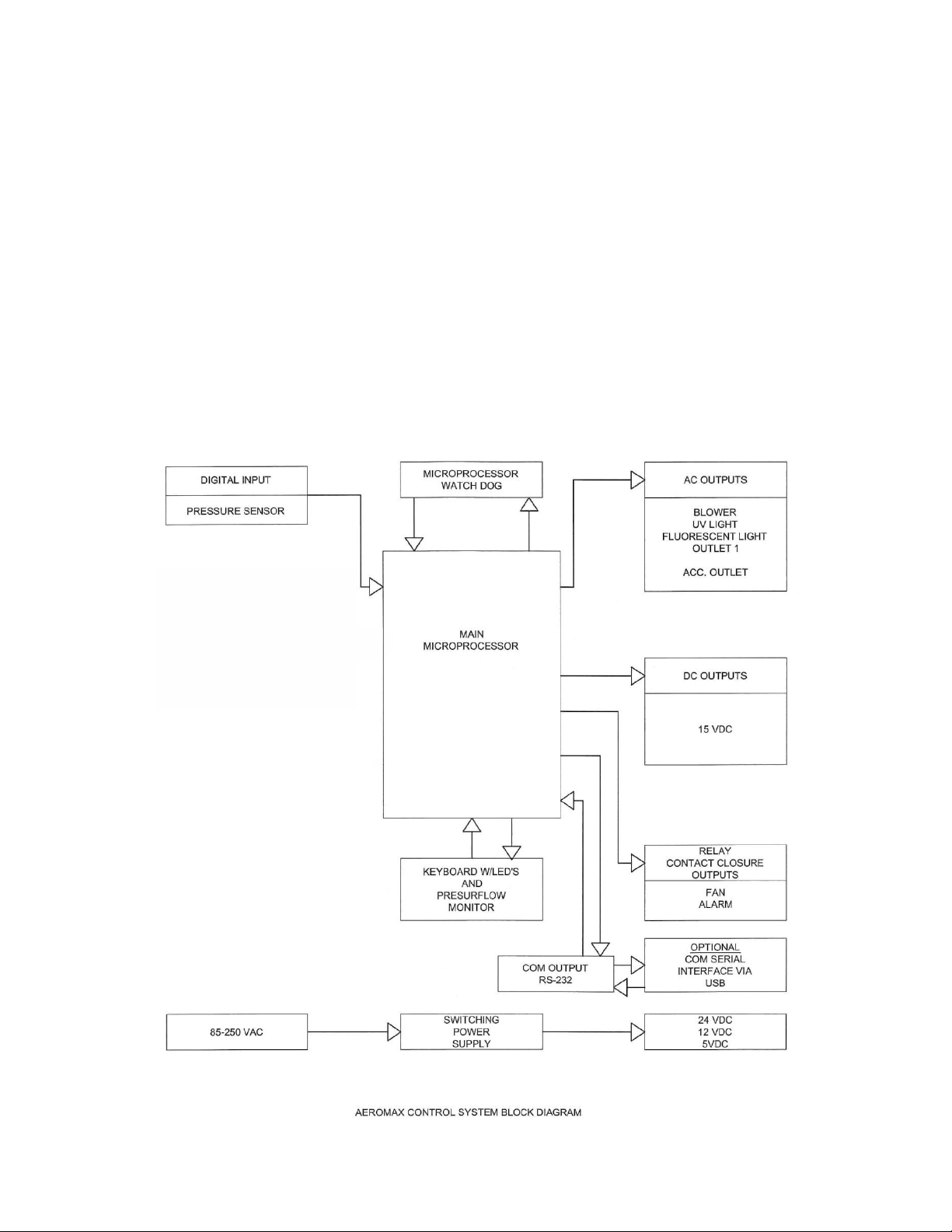
The Aeromax™ control system is designed to service the control requirements of the AireGard™ ES NU-240. The
Aeromax™ control system consists of an electronic module that will perform the following functions:
• Easy user interface via LED’s and function keys
• Control blower via solid state switch.
• Control lights via solid state switch.
• Disable audible alarm switch with ring back function.
• Control blower DC ECM motor/blower with solid-state DC Motor Controller that provides automatic
compensation for line voltage variances.
• Monitor and display airflow system performance via PresurFlow™ monitor.
The AireGard™ ES NU-240 offers the latest digital microprocessor design technology for improved performance
and safety. The Aeromax™ control system integrates a digital pressure sensor (PresurFlow™) to monitor the
airflow performance. The Aeromax™ control system also integrates a DC ECM motor/blower controller that
provides automatic compensation for both filter loading and line voltage variances. There is additional on/off
control of blower and light. All the above functions are shown in a system block diagram (see figure 1).
Figure 1
OM0267 Page 20 of 46
Rev 5 August/2019
Page 21
OM0267 Page 21 of 46
Rev 5 August/2019
Page 22

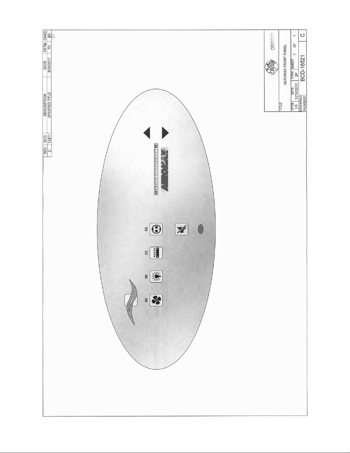
5.1.2 Front Panel
The control system front panel contains the following functions described in detail (see Drawing BCD-16521).
5.1.2.1 Blower Keys
The blower key controls the ON/OFF power to the blower.
LED above key indicates: full green for blower on,
blinking green for blower pending and
full red for blower alarm.
5.1.2.2 Hidden Key
The hidden key is located just above the blower LED indicator centered in the airflow symbol. The hidden key
is used for various functions including the blower password 3 key sequence if the option is activated.
5.1.2.3 Fluorescent Light Key
The fluorescent light key controls the on/off power to the fluorescent light.
LED above the key indicates full blue for fluorescent light on.
5.1.2.4 Ultraviolet (UV) Light Key (Diagnostic Key Use ONLY)
The UV light key controls the on/off power to the UV light (Diagnostic Key Use ONLY).
LED above indicates full yellow for UV light on.
5.1.2.5 Outlet Keys (Special Option Feature ONLY)
The outlet key controls the ON/OFF power to the outlets (Special Option Feature ONLY).
LED above indicates full blue for outlets on.
5.1.2.6 Red Alarm LED
The red alarm LED will indicate any alarm condition and remain indicating until the alarm condition is cleared.
5.1.2.7 Audible Alarm Silence
The audible alarm silence key allows user interaction to silence an audible alarm for a period of 15 minutes.
After 15 minutes if the alarm condition still exists, the audible alarm will again sound.
The audible alarm silence key also is used to exit all Aeromax™ user interaction menus.
5.1.2.8 Arrow Adjustment Keys
The arrow adjustment keys allow user interaction for various functions.
5.1.3 Aeromax™ Control System Power
After the AireGard™ ES NU-240 is plugged into the appropriate facility line power the control system will power up.
The control panel will also indicate the power up status by blinking the red alarm LED. Pressing any key will
acknowledge the power up status and turn off the blinking red alarm LED.
If a power interruption occurs, all control system functions, calibrations and parameters will be maintained and
continue upon restoration of power. Just as the initial power up, the red alarm LED will blink to indicate power up
status.
5.1.4 Standby Mode
When the NU-240 is not in use any of the function keys except the blower that initiates run mode may be turned
on and off in standby mode.
OM0267 Page 22 of 46
Rev 5 August/2019
Page 23

5.1.5 Run Mode
Any time the blower run key is pressed with the hinged window at its correct operational height, the RUN MODE
screen will be initiated. The Run Mode will start with the PresurFlow™ entering and approximate 3 minute warm
up period. The PresurFlow™ LED indicators will blink and indicate the following sequence:
st
minute – Left and right Red LED’s will blink
• 1
nd
• 2
minute – Left and right Green LED’s will blink
rd
• 3
minute – Center 3 Green LED’s will blink
Once the warm up period is complete, only one LED will indicate cabinet airflow status.
During the warm up period the cleaning process may begin.
5.1.6 Standby/Run Mode Alarms
If present, standby/run mode alarms will be both visual and audible, the red alarm LED oval will turn on. Audible
alarms will produce an alarm tone for 30 seconds, then ring back for 2 seconds of every 5 seconds. Pressing the
alarm silence key will silence the audible alarm for 15 minutes initially then will start the ring back function again.
The list below represents alarm types and their respective priority from the highest to lowest priority.
1) New Firmware Loaded
2) Internal Board Failure
3) Power on Reset
4) Airflow Pressure Alarm
5) Blower RPM Failure
Note: The above messages are described in greater detail in section 7.
OM0267 Page 23 of 46
Rev 5 August/2019
Page 24
5.1.7 Operator Accessible Functions
5.1.7.1 Access and Navigation
To access the operator accessible functions,
• Press and hold the key, then enter the 3 key sequence for the desired function, then release
The key and follow each instruction set.
Note: Pressing the key at any time will abort and exit the process without saving any changes
made. Pressing the hidden key will accept all changes and exit.
5.1.7.2 Auto Timer Duration
Auto timer duration timers are countdown timers for the functions displayed once time is entered into a
function. The timer will begin to countdown upon the start of that function (i.e. press light key to start timing
the light). The LED indicator above the function key will start to blink indicating the timer function. If the LED
indicator was full on, no timer function is present. As the timer expires the function will turn off.
• Select auto timer duration function
o Outlets (Special option feature only)
Press and hold key, then press hidden – outlet – outlet keys sequentially.
LED indicator above outlet will blink fast. Adjust desired time as described below.
o Lights
Press and hold key, then press hidden – light – light keys sequentially.
LED indicator above light will blink fast. Adjust desired time as described below.
o UV Light (Diagnostic key use only)
Press and Hold key, then press hidden – UV light – UV light keys sequentially.
LED indicator above UV light will blink fast.
Adjust desired time as described below.
• Low Flow Blower (Diagnostic key use only)
Press and hold key, then press hidden-blower-blower keys sequentially.
LED indicator above Blower key will blink fast. Adjust desired time as described below.
o Adjust countdown time
Press ↑ or ↓ keys to adjust time.
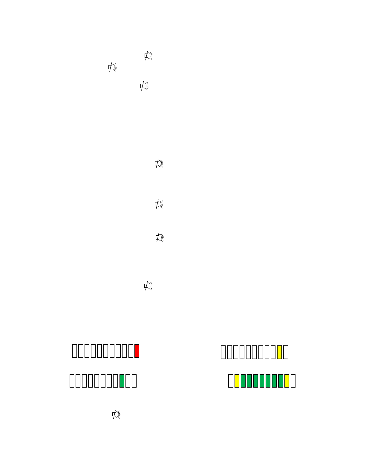
Time will change in 15 minute increments as shown on the PresurFlow™ LED segments
below.
15 minutes for Red LED 30 Minutes for Yellow LED
1 hour for green LED Represents 8 hours (maximum time)
• Press hidden key to accept time and exit.
• Press key at any time to abort and exit.
OM0267 Page 24 of 46
Rev 5 August/2019
Page 25
5.1.7.3 Blower Password
The blower on/off password allows the cabinet user to place a 3 key sequence requirement to turn the blower
on or off.
The 3 key sequence for the blower password will be a combination of the hidden and blower keys.
• Select blower password
Press and hold key, then press hidden – blower – hidden keys sequentially.
Red LED indicator above blower will blink fast.
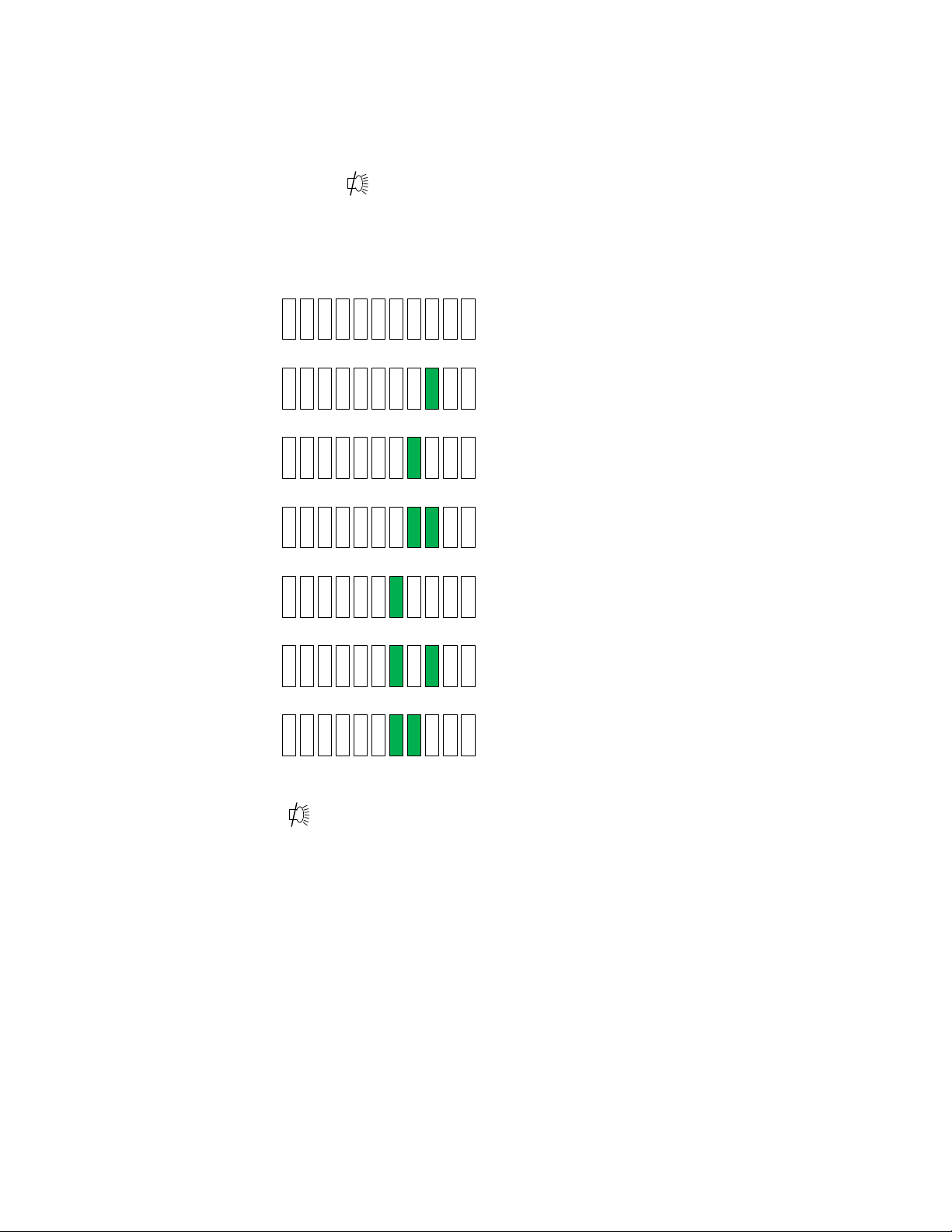
• Select password
Press ↑ or ↓ key to scroll through the code choices below,
No Password
B-B-H password
B-H-B password (default)
B-H-H password only
H-B-B password
H-B-H password
H-H-B password
• Press hidden key to accept time and exit.
• Press key at any time to abort and exit.
Note: If the required blower password option is selected in the blower airflow option menu (see section 7.2.2).
Then the “No password” choice above is not available and the default remains B-H-B.
OM0267 Page 25 of 46
Rev 5 August/2019
Page 26

5.2 Operating Guidelines
Operate the laminar flow workstation continuously. The unit will then remain in its initially clean condition. If, for any
reason, the unit is turned off, turn the unit on and permit to operate for 5 minutes before resuming operations.
Allow only essential items in the work station. Objects should not be placed between the HEPA filter and any point where
the clean environment must be maintained. New items introduced into the work area should be placed downstream of
items already in the work zone for several minutes to allow contaminants to flush off. Note that plastic parts may carry a
static charge which may require special handling in order to remove contaminants.
Particular care must be exercised in placing equipment within the work space. Where possible, equipment should be
placed on perforated platforms to allow air movement under as well as around the object.
All work should be performed with the operator's hand or head downstream of the critical process points. Unnecessary
movement with the work station should be kept to a minimum.
If the workstation is used in a manner not specified by NuAire, the protection provided by the equipment may be impaired.
5.2.1 Operating Sequence
A. Start Up
Turn on workstation blower and lights, check air intake ports of the workstation to make sure they are
unobstructed. The workstations are provided with gauges which indicate pressure differentials across the
filters. They indicate when to replace the filters, dependent upon the blower fan capacity. Blower speed must
only be readjusted by qualified maintenance technicians.
B. Good procedure includes the decontamination or wipe down of workstation surfaces with chemical
disinfectant before work commences.
C. Allow blowers to operate for a minimum of 5 minutes before aseptic manipulations are begun in the
workstation. An additional advantage is obtained from purification (filtration) of the room air circulated
through the equipment. Because of the characteristic contributed to the quality of the laboratory
environment, some owners leave them in operation beyond the time of actual use.
D. Minimize Room Activity - Activity in the room itself should be held to a minimum. Unnecessary activity may
create disruptive air currents, as well as interfere with the work of the operator. A person walking past the
front of the workstation can cause draft velocities up to 175 FPM, which are sufficient to disrupt the air
balance of the Laminar Flow Unit.
E. Utilize Unidirectional Airflow - The operator must keep two important facts in mind:
1) The air, as supplied to the work area through the HEPA filter is contaminant-free.
2) Airborne contamination generated in the work area is controlled by the unidirectional flow of parallel air
streams.
A solid object placed in a laminar air stream will disrupt the parallel flow and consequently, the capability of
controlling lateral movement of airborne particulates. A cone of turbulence extends behind the object and
laminarity of the air stream is not regained until a point is reached downstream, approximately equal to three
to six times the diameter of the object. Within the parameters of this cone, particles may be carried laterally
by multidirectional eddy currents.
5.3 Ergonomics
Ergonomics, the study or accommodation of work practices is extremely important for proper workstation usage and user
health and safety. An evaluation of normal work practices should be performed with each user when working in a
workstation. Evaluation criteria should be at a minimum:
a. Proper user posture
b. Effective workzone layout for work practice
c. Vision or sightlines
OM0267 Page 26 of 46
Rev 5 August/2019
Page 27

For each of the above evaluation criterion, several aids may be supplied to accommodate the user.
• Ergonomic chair - A six-way articulating seat and back control for personalized adjustment to assure proper user
posture. Be sure feet are resting on the floor, chair foot support or foot rest. Also be sure back is fully supported with
proper chair adjustments.
• Forearm/elbow support - The workstation is provided with a forearm support on the work access opening. Periodic
mini-breaks during work practice should be taken resting forearm to avoid stress and fatigue. Elbow rests are optional
that can provide support for particular work practices, such as pipetting.
• Effective workzone layout - Always prepare your work procedure to minimize reach to avoid neck and shoulder stress
and fatigue. Rotating tables are optional to maximum workzone and minimize reach.
• Vision and sightline - Always prepare your work procedure to eliminate glare and bright reflections on the window.
Keep your window clean and sightlines clear to your effect workzone.
5.4 Cleaning Procedures
5.4.1 General
Cleaning laboratory equipment is important in terms of both functionality and general good housekeeping. The
information provided below is intended to aid the development of facility Standard Operating Procedures (SOP’s) for
cleaning the equipment. It is strongly recommended that all cleaning materials used be tested and verified in terms of
both effectiveness and material compatibility before they are written into the cleaning SOP documentation.
a. The airflow blower should be operating during the cleaning process to maintain sterility and/or containment during the
cleaning process.
b. Avoid directly spraying the diffuser screen while installed as this may damage the HEPA filter. Remove the diffuser
screen and clean separately outside the unit.
c. Apply appropriate cleaning material or surface disinfectant to surfaces. Most surface disinfectants require a specific
contact time depending the materials used within the work zone. CONSULT APPROPRIATE DISINFECTANT
DOCUMENTATION FOR PROPER APPLICATION AND SAFETY PRECAUTIONS.
c-1. Polycarbonate (Covestro® Makrolon®AR) has noted material compatibility concerns (see polycarbonate compatibility
section). They recommend the use of Hydrogen Peroxide based materials such as the following:
It is recommended to AVOID the use of cleaning materials that contain Chlorine, Quaternary Ammoniums and Phenol’s.
If the polycarbonate is lightly scratched, it may be able to be polished out with Mirror Glaze Plastic Polish or similar.
Further information may be available from www.covestro.com
c-2. Stainless steel (type 304) has noted material compatibility concerns with Acids, Chlorides and Halogens. IF THESE
MATERIALS ARE USED AND ALLOWED TO BE LEFT ON THE STAINLESS STEEL SURFACE, OXIDATION AND DEGRADATION
WILL OCCUR. Only by re-wiping surfaces with either sterile water or 70% IPA will remove harmful materials from the
stainless steel surface.
Further information is available at the following: http://www.parrinst.com/wpcontent/uploads/downloads/2011/07/Parr_Stainless-Steels-Corrosion-Info.pdf
NOTE: NuAire does not offer any product warranty with respect to cleaning material compatibility. USE AT YOUR OWN
RISK! The information provided above is from raw material suppliers and known general source documents for use to
develop application cleaning SOP’s.
NOTE: When cleaning the work area for the first several times, the new metal surfaces may produce some dark
discoloration on the white cleaning wipes. Repeated cleaning will continuously reduce the amount of the discoloration
material on the cleaning wipes over time.
- Steriplex SD
- Safetec surface wipes
- Peridox RTU
OM0267 Page 27 of 46
Rev 5 August/2019
Page 28
6.0 General Maintenance
CAUTION
!
CAUTION
!
6.1 Fluorescent Lamp Replacement
6.2 HEPA Filter Replacement
6.3 Pre-Filter Replacement
6.4 Airflow Control System Setup and Calibration
OM0267 Page 28 of 46
Rev 5 August/2019
All maintenance actions on this equipment must be performed by a qualified
technician who is familiar with the proper maintenance procedures required for this
equipment. This includes both certification as well as repair.
The fluorescent lamps are T8, cool white and electronic start. The life rating of a lamp is 9000 hours based on three hour
burning cycles.
To replace a lamp:
1. Make sure the workstation light is off.
2. Remove (1) rear-screw at each top side of the top panel and pull out panel to access lamps.
3. Lamps are removed by rotating until the pins can be pulled down.
4. Reverse the procedure to reinstall lamps and reassemble unit.
The HEPA filter, under normal usage and barring an accident (puncture), does not need replacement until the efflux velocity
cannot be maintained at 90 LFPM (.457 m/s) + 10%. This may permit the HEPA filter efflux average to be as low as 81 LFPM
(.411 m/s), as long as no point falls below 70 LFPM (.355 m/s). Use only replacement filters of the same rated flow and size
as originally installed to insure proper airflow and HEPA filter lifetime can be achieved.
The HEPA Filter replacement procedure is performed by the following steps: Drawing BCD-19827):
Disconnect electrical power from the cabinet before attempting any maintenance
action.
1. Remove IV bars if installed.
2. Remove the unit diffuser screen(s) by lifting slightly and tipping out the diffuser screen(s) to remove through the
front of the unit.
3. Remove filter clamp by removing the #8 x 2.00” screw, #8 washers and compression springs (Detail “A” 4 places).
4. Slightly lift and tip out filter and remove through front of the unit.
NOTE: This step usually requires 2 people for the removal and replacement of the HEPA filter.
5. Replace HEPA filter by tipping the filter into place resting on plenum bottom.
6. Reattach filter brackets and hardware 4 places and tighten uniformly.
7. Replace the unit diffuser screen(s) by tipping into place, lifting slightly to all screen bottom to fall into groove in
work surface and to fit screen to catch the top angle to rest in place.
The replacement interval depends on the contaminant (large particles or lint) in the room -- a typical period is every 6
months. The prefilters are located on the top of the workstation.
6.4.1 General
The operation of the NU-240 requires that the setup and calibration procedures be performed in order to certify or
commission for usage. The setup and calibration procedures performed ONLY BY THE CERTIFIER ensure that
setpoints are verified and that the airflow monitor sensor is calibrated to the correct values.
Page 29
6.4.2 Configuration Parameters
Configuration parameters identify NU-240 motor type and size for proper performance characteristics.
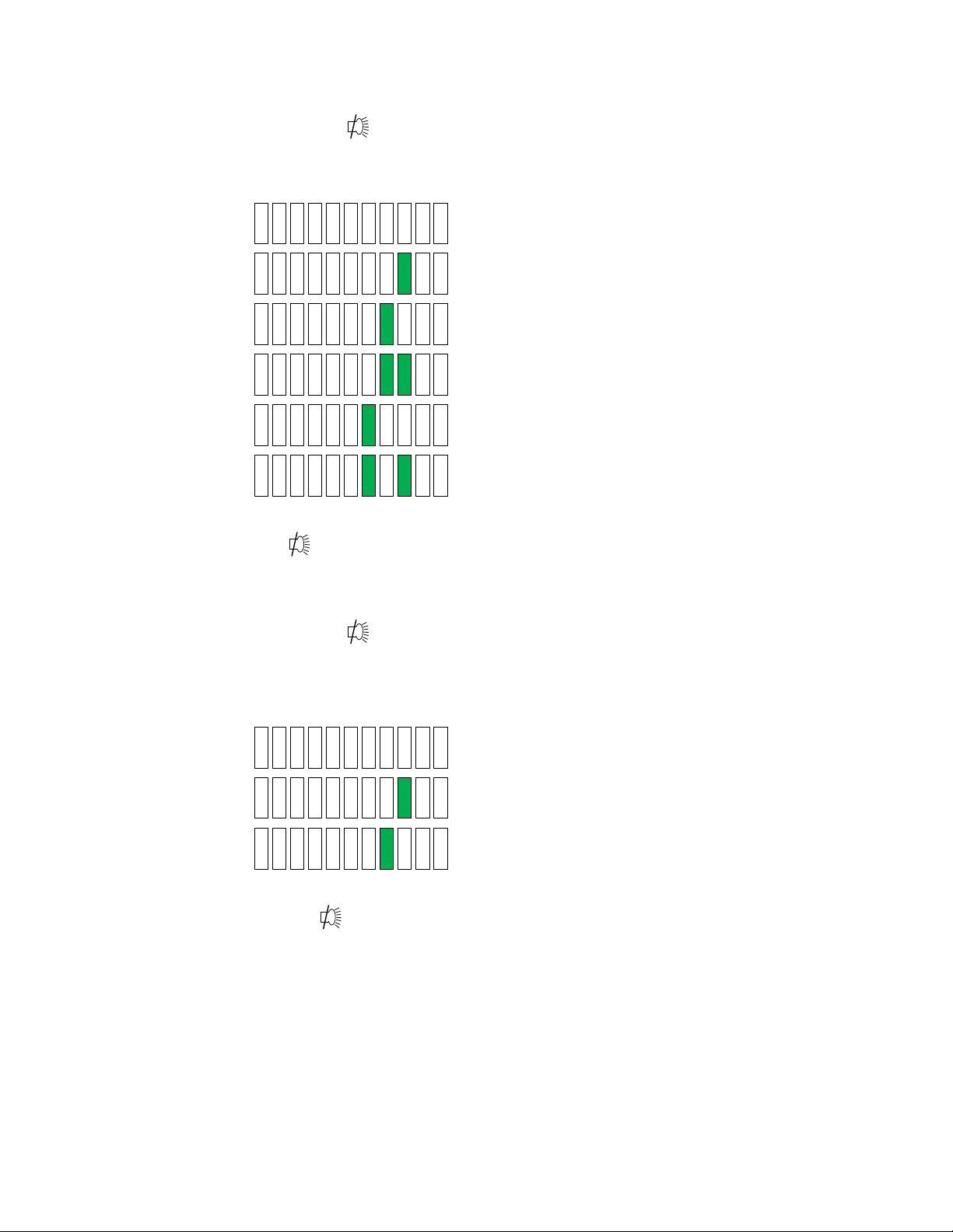
• Select/Verify model and size (Bold items represent default parameters)
o Press and hold key, then press blower – blower – blower keys sequentially.
LED indicates above both blower (red) and UV light keys will blink fast.
Review model type/size and change if desired as described below
o Press ↑ or↓ keys to scroll through the LED segment choices associated with model type/size.
Class II, 3 foot
Class II, 4 foot
Class II, 5 foot
Class II, 6 foot
Laminar, 3/4 foot
Laminar, 5/6 foot
o Press hidden key to accept model/size and exit
o Press key at any time to abort and exit
• Select motor control function/type
o Press and hold key, then press light – light – light keys sequentially.
LED indicators above both blower (red) and light keys will blink fast.
Review motor control function/type and change it desired as described below.
o Press ↑ or ↓ keys to scroll through the LED segment choices associated with motor control
function/type.
Auto DC ECM motor
Fixed duty DC ECM motor
Fixed duty EC Impeller motor
o Press hidden key to accept motor control function/type and exit
o Press key at any time to abort and exit.
OM0267 Page 29 of 46
Rev 5 August/2019
Page 30
6.4.3 Airflow Calibration
CAUTION
!
The NU-240 Airflow Calibration consists of adjusting the airflow.
THIS WORK SHOULD BE DONE ONLY BY A QUALIFIED TECHNICIAN WHO CAN MEASURE THE AIRFLOW WITH A
SUITABLE VELOMETER. NuAire provides one adjustment to set the airflow within the cabinet.
This is: PWM signal adjust via calibration parameter menu.
The PWM signal or blower speed adjustment establishes the NU-240 total volume of airflow as well as makes up
for filter resistance tolerances.
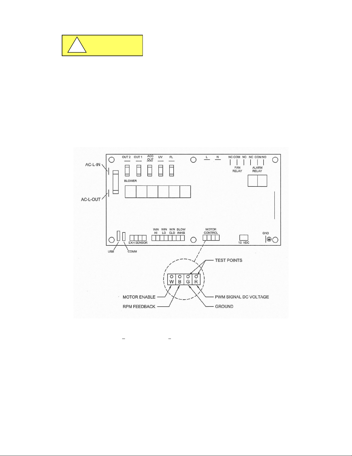
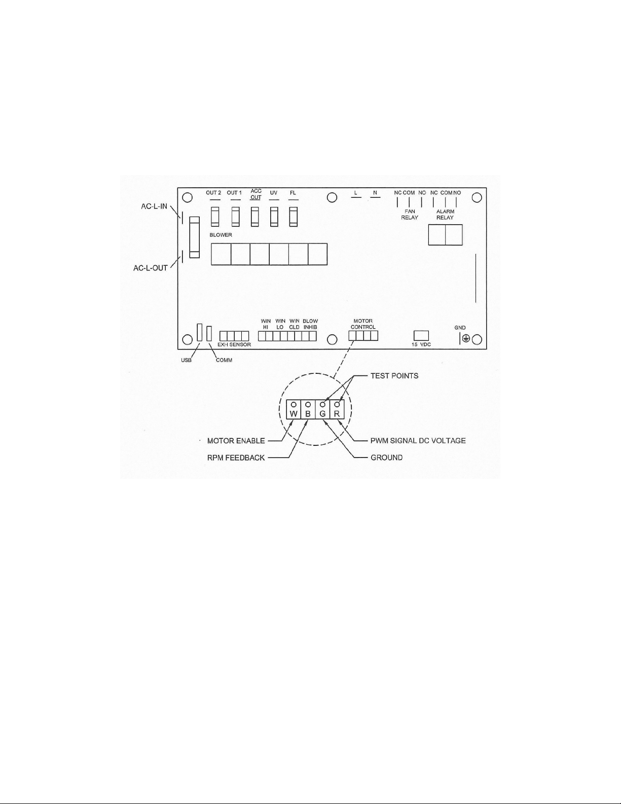
DC ECM motor PWM signal DC voltage should also be monitored and recorded upon final calibration. The DC
voltage may be measured using a digital voltmeter. The two test points to measure DC ECM motor voltage are
located on the DC motor connector on the main control board.
Failure to calibrate airflow to the specified requirements may result
in unsafe conditions of performance (i.e. product protection, noise and
vibration)
BEFORE STARTING AIRFLOW CALIBRATION PROCEDURE, LET THE NU-240 RUN FOR AT LEAST 5 MINUTES.
OM0267 Page 30 of 46
Rev 5 August/2019
The NU-240 is considered to be certifiable if the following airflow measurements are present:
Inflow average: 90 LFPM + 10 LFPM (.46 m/s + 0.05 m/s) using the direct inflow measurement method or related
value using the calculated inflow velocity measurement method.
Page 31
6.4.3.1 Airflow Calibration
Step 1: Measure the inflow velocity using the recommended procedure found in Table 6.0. If necessary, adjust to
achieve the correct average miniflow velocity within the stated range of 90 + 10 LFPM (.46 + 0.05 m/s).
Step 2: If necessary, enter active blower speed adjustment.
• Press and hold key, then press hidden – blower - ↑ keys sequentially.
LED indicator above blower (green) key will blink fast.
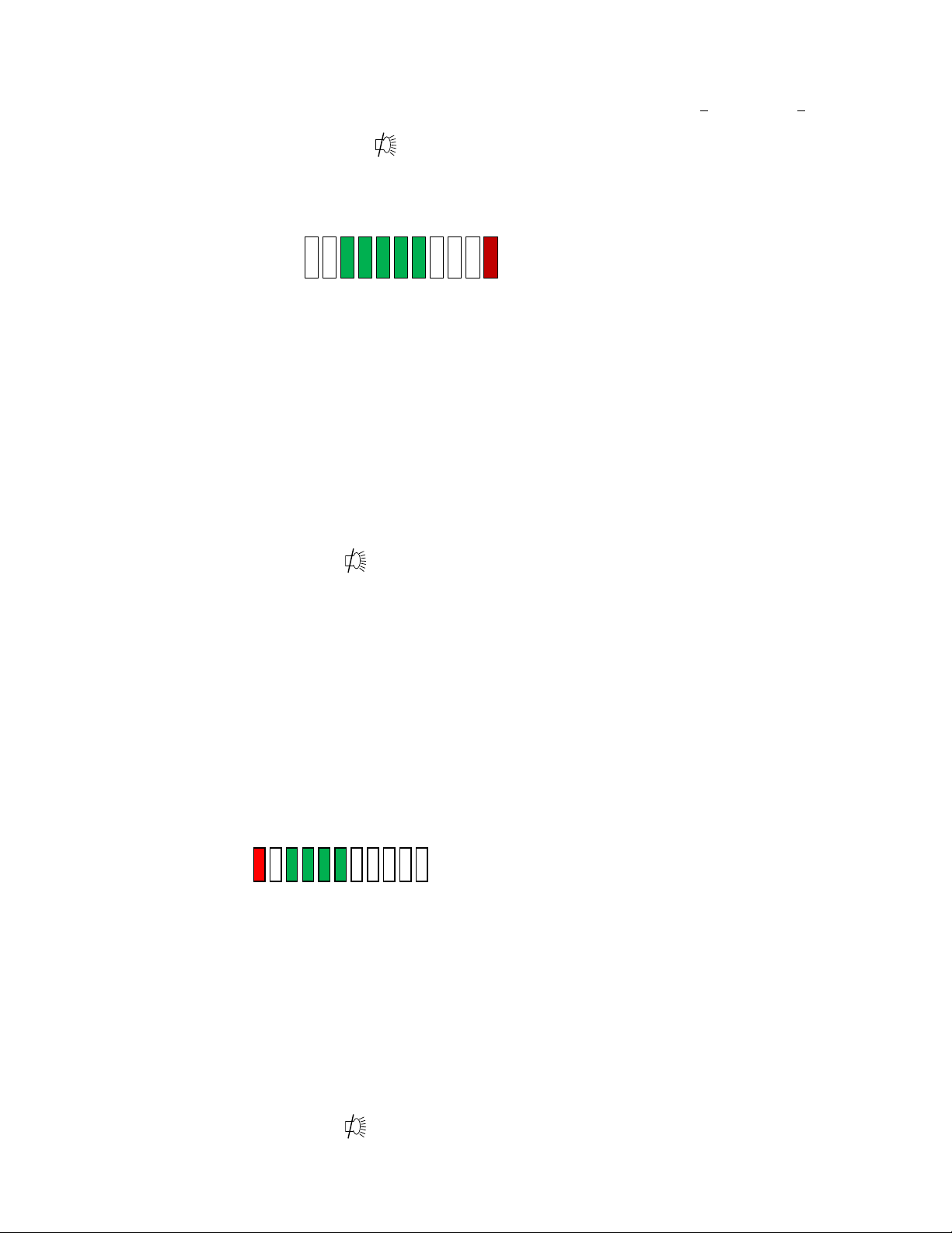
Step 3: Press ↑ or ↓ keys to adjust blower speed.
• LED segments will indicate blower speed percentage and active blower speed adjustment
o Right end red LED indicates active blower speed adjust
The red LED will blink as soon as any adjustments are made and will continue to blink as the
motor rpm settles. Once the red LED stops blinking, the motor will run steady state at the
new percentage.
Note: The red LED must be non-blinking to save or exit
o Green LED’s indicate percentage on of scale (0-100%)
o Yellow LED’s indicate minimum (left/maximum (right) blower speed has been achieved
Note: At any time during the process
• Press hidden key to accept and enter the blower speed calibration point
(If the blower speed calibration point was not successfully entered; a half second audible
alarm will occur. The calibration process must then be repeated for successful entry of
blower speed calibration point.)
• Press key to abort and exit
6.4.3.2 PresurFlow™ Alarm Set Points
The PresurFlow™ alarm setpoints are based on the calibration setpoint. Once the calibration setpoint is
entered, based on a nominal inflow velocity of 90fpm (.46mls) the associated pressure sensor value is entered
as the nominal pressure value. The high and low alarm setpoints are factory verified and set if needed at
90LFPM (.46 m/s).
However, if specific use alarm setpoints are desired, the alarm setpoints may be adjusted by performing the following: Low Alarm Setpoint
• Press and hold the Hidden and↓ key for 3 seconds. (The left red LED will blink and the green LED’s indicate blower speed)
• Press ↑ or ↓ keys to adjust blower speed to the desired airflow velocity low alarm setpoint value.
• Left end red LED indicates active low limit blower speed adjust
The red LED will blink as soon as any adjustments are made and will continue to blink as the motor rpm settles. Once the red LED stops blinking, the motor will run steady state ate the new percentage.
If the low alarm setpoint value is not within an acceptable range, the left end red LED will blink at a very fast rate.
Note: The red LED must be non-blinking to save or exit.
Note: At any time during the process
• Press hidden key to accept low alarm setpoint value
• Press and hold outlet key for three seconds to remove any previous offsets
• Press key to abort and exit
• Upon exiting, the blower will go back to actual airflows.
OM0267 Page 31 of 46
Rev 5 August/2019
Page 32
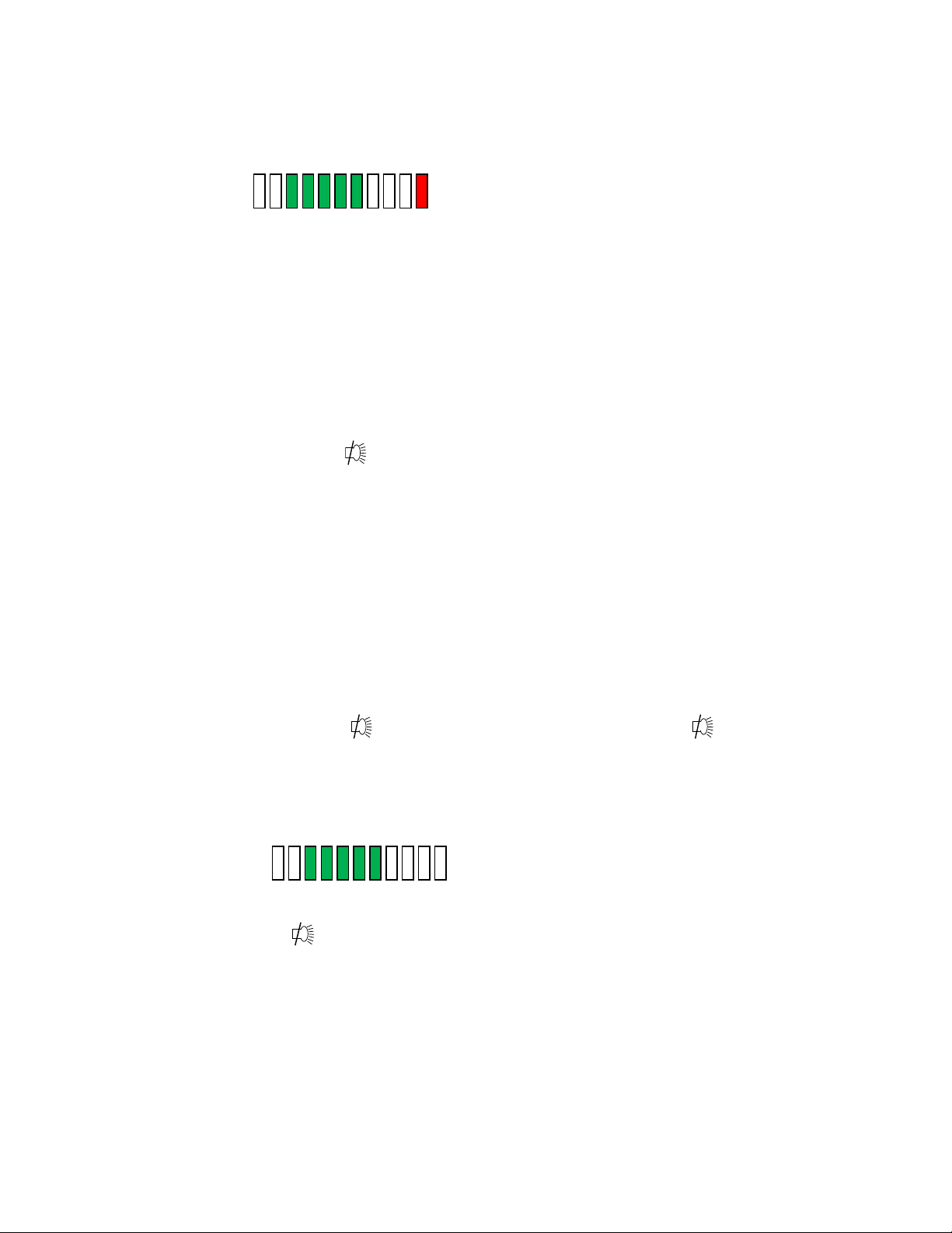
High Alarm Setpoint
• Press and hold the Hidden and ↑ key for 3 seconds. (The right red LED will blink and the green LED’s indicate blower speed)
• Press ↑ or ↓ keys to adjust blower speed to the desired airflow velocity high alarm setpoint value.
• Red end Red LED indicates active high limit blower speed adjust.
The red LED will blink as soon as any adjustments are made and will continue to blink as the motor
rpm settles. Once the red LED stops blinking, the motor will run steady state at the new percentage.
If the high alarm setpoint value is not within an acceptable range, the right end red LED will blink at a
very fast rate.
Note: The red LED must be non-blinking to save or exit.
Note: At any time during the process
• Press hidden key to accept low alarm setpoint value
• Press and hold outlet key for three seconds to remove any previous offsets
• Press key to abort and exit
• Upon exiting, the blower will go back to actual airflows.
Note: Specific use alarm setpoints or the offset pressure value from the nominal calibration point will
be maintained with a new nominal calibration value.
It is not necessary to re-enter the alarm setpoints after a nominal calibration.
6.4.3.3 PresurFlow Alarm Verification
The PresurFlow Alarm setpoints are based on the calibration setpoint. Once the calibration setpoint is
entered, the Alarm setpoint offset pressure values will align from the calibration pressure value. The high
or low alarm setpoint can be verified by measuring inflow volume/velocity while adjusting blower up or
down within the Alarm Verification menu.
• Press and hold key, then press ↑ ↓ ↑ sequentially releasing the key after the 3 key
sequence.
• Note: If blower was off while entering into the Alarm Verification Menu, the low alarm limit will
immediately activate. Turn on blower; once airflow is above the low alarm limit, the alarm will turn
off.
• LED segments will indicate blower speed percentage.
• Press ↑ or ↓ key to raise or lower blower speed. Alarm is active so yellow and red LED’s will activate
if pressure reaches the low or high alarm limit.
• Press to exit (blower should turn off and not go through normal start up procedure).
OM0267 Page 32 of 46
Rev 5 August/2019
Page 33

Table 6.0
Airflow Velocity Profile
A. Instruments: TSI 8355 Thermo anemometer
B. Procedure:
Air velocity readings are taken on a 12 inch (305mm) grid, in a plane parallel to and 6 inches (152mm) from the filter
surface. No reading should be taken closer than 6 inches (152mm) from the inner edge of the filter frame.
C. Test Data:
Number of Readings: Average Velocity: ft./min. m/s
D. Acceptance Criteria:
1. Average Velocity = 80 to 100 fpm (.41 to .51 m/s)
2. Individual Readings must be within ±20 percent of the average velocity
__________ to __________ fpm (__________ to __________ m/s).
OM0267 Page 33 of 46
Rev 5 August/2019
Page 34

6.5 HEPA Filter Leak Test
Model Size
Filter Area (ft2)(m2)
Model Size
Filter Area (ft2)(m2)
330
7.5 (.213)
530
12.5 (.354)
336
9 (.255)
536
15 (.425)
430
10 (.283)
630
15 (.425)
436
12 (.340)
=
=
In order to check filter and filter seal integrity, the HEPA filter media and seals must be directly accessible, by the
measuring instrument. The challenge material (i.e. PAO) should be supplied in the top panel of the workstation. An
upstream challenge may be taken by using the minihelic gauge pressure supply tube if desired.
The diffuser is secured by thumb screws on the sides.
Once removed the diffuser can be lifted up slightly using the small handles and removed from the cabinet.
Laskin Nozzle Concentration Formula
# Nozzles x 135 CFM x 100 ug/L Challenge
CFM Concentration (ug/L)
# Nozzles x 229 CMH x 100 ug/L Challenge
CMH Concentration (ug/L)
6.6 Cleanliness Classification Test for Pharmacy Application
If this cabinet is going to be used within pharmacy, per USP797
ISO 14644-1:2015, Cleanrooms and Associated Controlled Environments, Part 1: Classification of Air Cleanliness
cleanliness classification test is performed using a particle counter to measure particle counts within the cabinet workzone.
Turn on cabinet and let warm up for several minutes. Turn on particle counter and flush out sample tubing line to remove
latent particles. Set the particle counter to measure 0.5 micron or larger particles at the appropriate measuring rate.
3
“Operational Particle Count Test
”
Position the particle counter isokinetic probe at a point 6 inches (152mm) upstream of the aseptic manipulation area (hand
convergence point) and mounted so as not to interfere with the operator’s hand movement. The pharmacy operator will
simulate IV manipulation during the particle count test using non-hazardous materials. A minimum of three (3) 1-minute
particle counts shall be sampled and recorded while the user simulates aseptic compounding manipulations.
“At Rest Particle Count Test”
Take 5 test points in 1-minute intervals on a grid, in a horizontal plane as measured approximately 6-inches (152mm)
parallel to the diffuser. The grid location is designed as the diffuser center point and each corner measured 6-inches
(152mm) from the inside perimeter.
Record the 5 particle count values for each of the test points over the 1-minute sample time. All final count particle
concentrations and calculated 95% upper confidence limit shall not exceed 3520 particles per cubic meter (ppcm) or (100
particles per cubic feet (ppcf).
1
USP28-NF23: United Stated Pharmacopeial Convention, Inc., 12601 Twinbrook Parkway, Rockville, MD
20852, USA, www.usp.org
.
2
ISO 14644-1:2015 Cleanrooms and Associated Controlled Environments-Classification of Air Cleanliness, International
Organization for Standardization, Case Postale 56, CH-1211 Geneve 20, Switzerland
3
CAG-002-2006: CETA Compounding Isolator Testing Guide, Controlled Environment Testing Association, 1500 Sunday
Drive, Suite 102, Raleigh, NC 27607, USA, www.cetainternational.org
1
, the cabinet must be tested to assure compliance to
2
. The
OM0267 Page 34 of 46
Rev 5 August/2019
Page 35
OUTLET FUSE
(Option Only)
ACCESSORY OUTPUT FUSE
(Option Only)
CAUTION
!
CAUTION
!
6.7 Main Control Board Description and Replacement
To access the main control board for fuse or board replacement, remove (1) rear screw at each top side of the top panel
and pull out panel to access. Now the main control board is exposed for service.
6.7.1 Main Control Board Replacement
The main control board consists of one Printed Circuit Board (PCB) assembly.
The PCB contains the power supply, configuration switch, sensor inputs/outputs and control inputs/outputs
components and display.
6.7.2 Main Control Board Fuse Replacement
Disconnect electrical power before fuse replacement.
All AC circuits are fuse protected and when replacement is necessary, USE ONLY FUSES OF SAME TYPE AND RATING
FOR PROTECTION AGAINST RISK OF FIRE.
6.7.3 Main Control Board Replacement
Note: All setup and calibration data will be lost, the memory reinitialized to the default values and all control
If possible, before the main control board replacement, it would be preferred to know the operational
DESCRIPTION: BLOWER FUSE
FUSE TYPE: TIME-LAG TIME-LAG TIME-LAG TIME-LAG
FUSE SIZE: 1/4 X 1-1/4 INCH 5 X 20MM 5 X 20MM 5 X 20MM
NU-240-3XX 8 AMPS 3 AMPS 2 AMPS 1 AMP (2)
NU-240-4XX 10 AMPS 3 AMPS 2 AMPS 1 AMP (2)
NU-240-5XX 10 AMPS 3 AMPS 2 AMPS 1 AMP (2)
NU-240-6XX 10 AMPS 3 AMPS 2 AMPS 1 AMP (2)
functions reset to an initial cabinet power condition.
parameters of the cabinet, (i.e. blower speed/PWM signal DC voltage setpoints if modified and airflow data
from previous certification).
The main control board is fastened to the control center with (6) 6-32 studs/nuts. All electrical connections are
made with removable terminals and/or Faston connectors except for the motor/blower connector which uses a
screw terminal. Remove all electrical connections and fasteners and then remove the main control board from the
control center.
Install new main control board by reattaching all electrical connections and fasteners. Once installed, rotate
control center to normal position and fasten in place. Reconnect power to cabinet.
LIGHT FUSES
OM0267 Page 35 of 46
Rev 5 August/2019
Page 36

Issue
Error Description
Correction
Check light fuse on main control board.
Check ballast.
Check blower fuse on main control board.
control board.
Indicates a power interruption has
occurred.
Check for short on output of fuse.
short.
Message acknowledges new
microprocessor
7.0 Error Messages, Troubleshooting, Option-Diagnostics and Airflow Sensor Performance Verification
Audible alarms and error messages occur for a variety of reasons. Whenever an alarm condition has been present for a
period of at least 10 seconds, the audible alarm/error message will be presented and stay on until the error is cleared. The
audible alarm will be on for 30 seconds upon initial alarm condition, then once every ten seconds. When presented with an
error message, please perform the following:
Step 1: NOTE ALL ERROR MESSAGES.
Error message will appear on the control panel with red LED’s.
Step 2: VERIFY ERROR MESSAGES.
Error messages can be verified by clearing the error function by either turning the blower or the cabinet on
and off.
Step 3: MONITOR RE-OCCURRENCE OF ERROR MESSAGES.
If re-occurrence of the error message is immediate or daily, use the following guide to correct the situation.
7.1 Error Message Troubleshooting Guide
Check fluorescent lamps.
Cabinet fluorescent
lights won’t Turn on
Blue LED above light key indicates the
lamp should be on.
Check voltage coming out of main control
board to light ballasts.
Check light starters, if present.
Cabinet blower won't
turn on.
Red alarm LED blinks
Blower or light fuse
continues to blow after
replacement.
PresurFlow™
left red LED indicator on
and red LED alarm
PresurFlow™
right red LED indicator
on
and red LED alarm
All PresurFlow™
LED’s blink
Green LED above blower key indicates
the blower should be on.
Airflow Alarm.
N/A
PresurFlow™ reading low flow
(pressure)
PresurFlow™ reading high flow
(pressure)
firmware was loaded into
Check AC voltage coming out of main
control board.
Check wiring to blower.
Check blower motor.
Check DC motor PWM signal on main
Press any key to clear.
Isolate output of fuse by disconnecting
control center connectors, light circuit,
AC or DC blower circuit, etc. to isolate the
Check airflow values.
Check blower function.
Recalibrate PresurFlow™ system.
Check airflow values.
Recalibrate PresurFlow™ system.
N/A
Blower red LED blinks
and red LED alarm
OM0267 Page 36 of 46
Rev 5 August/2019
Indicates that the motor rpm signal
has been interrupted
Check connectors and wires from main
control board to the motor
Replace motor if required
Page 37
7.2 Option Parameters
The option parameter menu allows A QUALIFIED TECHNICIAN to configure several different optional parameters per the
menu as described below.
7.2.1 Sync Function with Active Blower
To access the option parameter menu, perform the following:
• Press and hold key, then press hidden - Blower - Fluorescent keys sequentially.
Red LED indicator above the blower key will blink fast
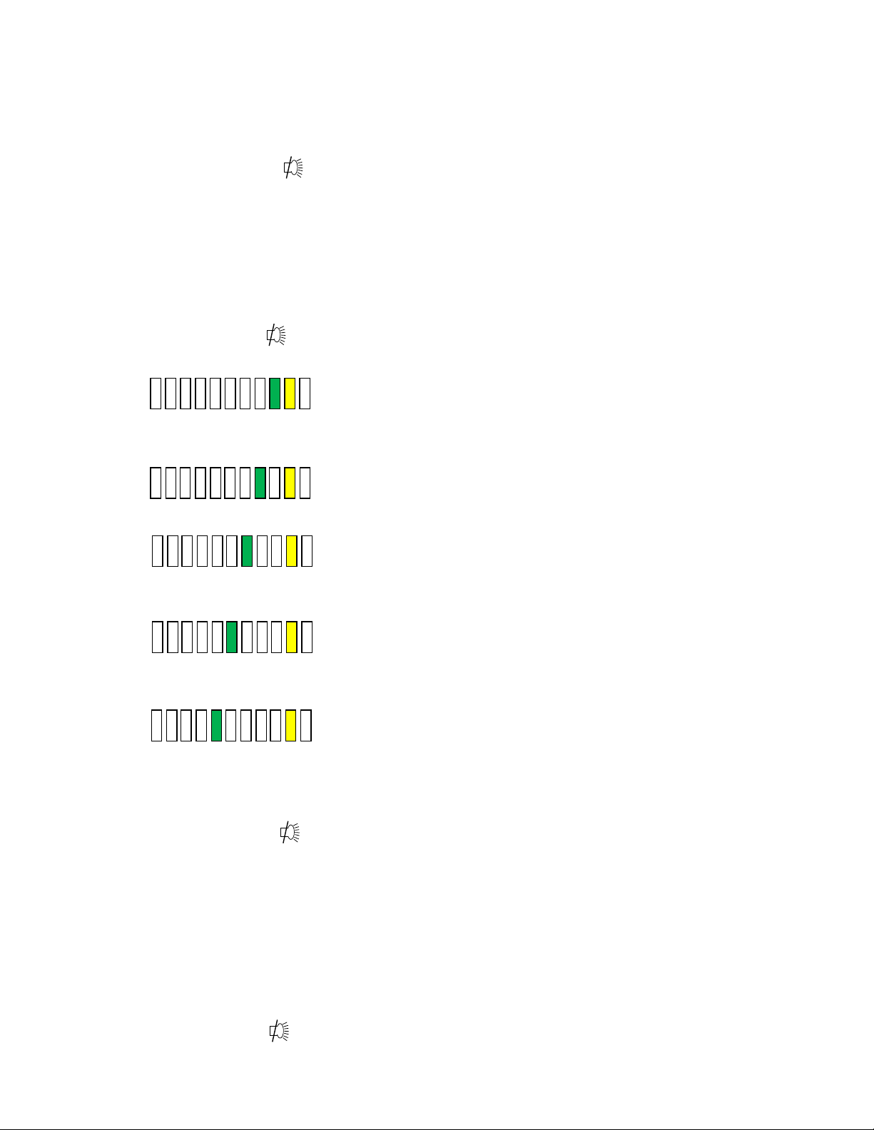
The PresurFlow™ blinking green LED segments will indicate seven optional parameters as shown and described
below. The UV Light key (move lefts) and outlet key (move right) allows selection of the option parameter desired.
Once the desired option parameter is indicated, press ↑ or ↓ key to turn on or off. A slow blinking green LED
indicator means off and a fast blinking green LED indicator means on. Multiple option changes can be selected.
• Pressing the hidden key will accept all changes and exit
• Pressing the key will abort the process and exit
Sync Fan Relay with Active Blower -
Normally the fan relay will activate when the blower switch is pressed. Blower can
either be actively running or pending. If the fan relay sync is active the blower must
be actively running for the relay to change state.
Sync Accessary Outlet with Active Blower - (only usable if accessory outlet is installed)
Normally the accessary outlet is on all the time. If the accessary outlet sync is active,
the blower must be actively running for the accessary outlet to turn on.
Sync Outlet Power with Active Blower - (only usable if outlet is hardwired to control
board) Normally the outlet power is turned on via the outlet key. If the outlet power
sync is active, the outlet power will turn on and off with the blower or may be turned
on and off independently if the blower is active.
Sync Fluorescent Light with Active Blower -
Normally the fluorescent light is turned on via the fluorescent light key. If the
fluorescent light sync is active, the fluorescent light will turn on and off with the
blower or may be turned on and off independently if the blower is active.
Sync 15 Volt DC output with active blower normally the 15 Volt DC output located on
the control board is on when power is applied to the system. If the 15 Volt DC output
sync is active, the blower must be actively running for the 15 Volt DC output to turn
on.
7.2.2 Blower/Airflow Options
To access the option parameter menu, perform the following:
• Press and hold key, then press hidden - ↑ and ↓keys sequentially.
Red LED indicator above the blower key will blink fast
The PresurFlow™ blinking green LED segments will indicate seven optional parameters as shown and described
below.
The UV Light key (moves left) and outlet key (moves right) allows selection of the option parameter desired.
Once the desired option parameter is indicated, press ↑ or ↓ key to turn on or off. A slow blinking green LED
indicator means off and a fast blinking green LED indicator means on. Multiple option changes can be selected.
• Pressing the hidden key will accept all changes and exit
• Pressing the key will abort the process and exit
OM0267 Page 37 of 46
Rev 5 August/2019
Page 38
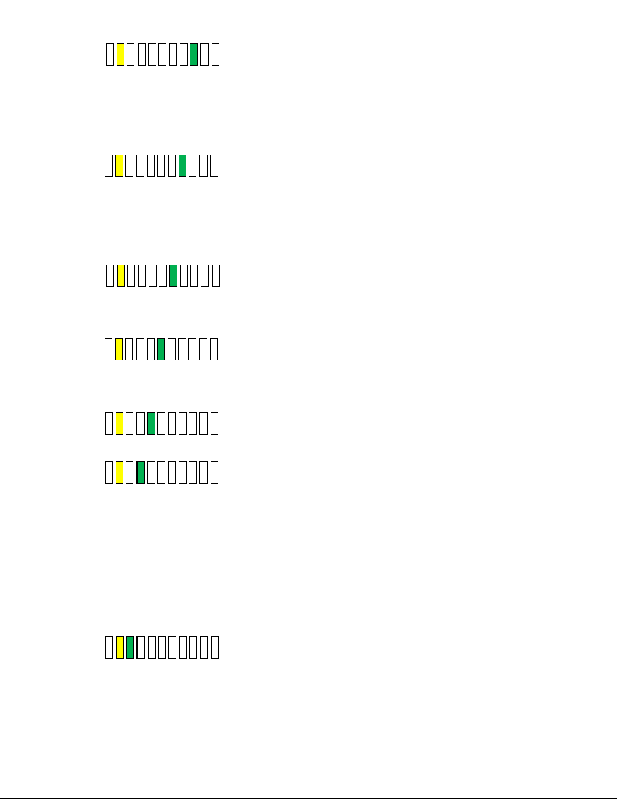
Require Password –
Normally it is not required to use a password (i.e. 3 key press sequence of the blower
and hidden key). If the option is turned on, it would be required to use the correct
password to turn on the blower. The default password once turned on is blowerhidden-blower keys in sequence. The password can be changed in the blower
password option menu.
Note: If turning off the password option, you must also select the no password menu
item (see section 5.1.8.3)
Allow UV light anytime – (not available on product)
Normally the UV light is interlocked with the window being in the closed position.
For service purposes only, if the function is active, the UV light may be turned on at
any window height.
Note: In addition to the Allow UV light anytime system function, there is a double redundant UV light
window interlock relay. To override the UV light window interlock relay, the relay itself must
also be shorted. (See electrical schematic for reference).
Manual Blower Restart –
Normally when the blower is actively running and a power interruption occurs.
The blower will automatically come back on when power is restored. If this function
is turned off, the blower will not automatically come back after a power interruption,
but would require the user to press the blower key to restart the blower.
Low Flow –
Normally the function is turned off. If selected and turned on, once the blower is
actively running. Upon closure, the blower will continue to run at a calibrated lower
speed level to maintain a negative airflow. The PresurFlow™ will indicate(s) blinking
green LEDs along with green LED above blower key.
Disable PresurFlow™ -
If this function is active, the digital pressure sensor and alarm function are turned off.
Temporary Low Flow -
When this option parameter is turned on and the other requirements below are met,
the blower key (when held for 5 seconds) will toggle blower between normal and Low
Flow blower speed. The Low Flow blower will time out, based on the Auto Timer
duration for Low Flow without a blower key press and the blower speed will revert
back to normal.
In addition to turning this option on the following requirements must also be met
• Temporary Low Flow Option must be selected
• Password Option must be selected
• Window is at normal height and blower is running
• Low Flow Option must be selected
• Low Flow blower auto timer must be set for a minimum of 15 minutes.
Disable audible alarms / audible key feedback
Normally audible alarms from the PresurFlow™ monitor and audible key feedback are
present to provide an audible sound to the user. If this function is active, all audible
sound will be silenced when the control system is in normal run mode. Audible sound
will still occur in any service/calibration menu function.
OM0267 Page 38 of 46
Rev 5 August/2019
Page 39
8.0
OM0267 Page 39 of 46
Rev 5 August/2019
Page 40
9.0 Remote Contacts
The NU-240 has several contact closures for remote sensing of various functions.
9.1 Fan Relay
The fan relay contacts are normally open and closed contact closure outputs that are activated whenever the blower key
is pressed and the blower key LED indicator is on or blinking. Contact ratings are 250 VAC maximum at 2 Amps.
9.2 Alarm Relay
The alarm relay contacts are normally open and closed contact closure outputs which are activated whenever an airflow
alarm condition occurs. Contact ratings are 250 VAC maximum at 2 Amps.
9.3 15VDC Output
The 15VDC (100mA) output is generated if the blower is actively running.
OM0267 Page 40 of 46
Rev 5 August/2019
Page 41

10.0 Electrical/Environmental Requirements
Electrical
Voltage
Phase
Frequency
Current
(Amps)
Independent Outlet Current for
Each Outlet (Optional)
NU-240-330
115 Volts
1
60 Hz
7
10
NU-240-336
115 Volts
1
60 Hz
7
10
NU-240-430
115 Volts
1
60 Hz
8
10
NU-240-436
115 Volts
1
60 Hz
8
10
NU-240-530
115 Volts
1
60 Hz
8
10
NU-240-536
115 Volts
1
60 Hz
8
10
NU-240-630
115 Volts
1
60 Hz
8
10
WARNING
!
10.1 Electrical (Supply voltage fluctuations not to exceed +/- 10%)
10.2 Operational Performance (for indoor use only)
Environment Temperature Range: 60°F - 90°F (15.6°C - 32.2°C)
Environment Humidity: Maximum relative humidity 80% for temperatures up to
31°C decreasing linearly to 50% relative humidity at 40°C
Environment Altitude: 6562 Feet (2000 Meters) maximum
10.3 Light Exposure
Standard Fluorescent Lighting @ 150 ft. candles (1614 LUX) maximum intensity.
10.4 Installation Category: 2.0
Installation category (overvoltage category) defines the level of transient overvoltage which the instrument is designed to
withstand safely. It depends on the nature of the electricity supply and its overvoltage protection means. For example,
in CAT II, which is the category used for instruments in installations supplied from a supply comparable to public mains
such as hospital and research laboratories and most industrial laboratories, the expected transient overvoltage is 2500V
for a 230V supply and 1500V for a 120V supply. Main supply fluctuations are not to exceed +10% of nominal voltage.
10.5 Pollution Degree: 2.0
Pollution degree describes the amount of conductive pollution present in the operating environment. Pollution degree 2
assumes that normally only non-conductive pollution such as dust occurs with the exception of occasional conductivity
caused by condensation.
10.6 Chemical Exposure
Chemical exposure should be limited to antibacterial materials used for cleaning and disinfecting. Chlorinated and
Halogen materials are not recommended for use on stainless steel surfaces.
10.7 EMC Performance (classified for light industrial)
Emissions: EN61326
Immunity: EN61326
The EMC performance requirements are generated within the product
enclosure. The enclosure will be all metal grounded to earth.
In addition, the membrane front panel will also include a ground plane for
maximum protection and an electrostatic shield.
OM0267 Page 41 of 46
Rev 5 August/2019
Page 42
11.0 Disposal and Recycle
Component
Material
Main Workstation
Painted Steel
Worksurface
PVC / Stainless Steel
Side Panels
Polycarbonate / Stainless Steel
HEPA Filter Frame
Aluminum
Control Center
Painted Steel
Diffuser
Aluminum
HEPA Filter
Aluminum
Hepex Bag
PVC
Blower Wheel & Housing
Steel
Motor
Various Steel / Copper
Printed Wiring Assembly
Lead Free Electronic
Wire
PVC Coated Copper
Ballasts
Various Steel, Electronic
Connectors
Nylon
Hardware
Stainless Steel and Steel
NOTE:
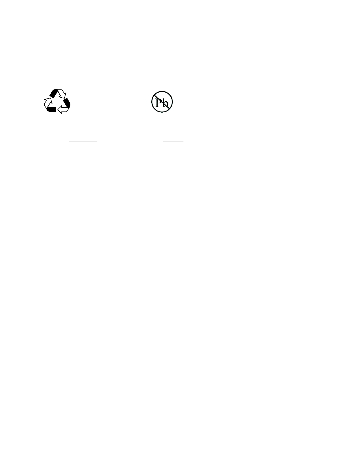
RECYCLE
LEAD FREE
Workstations that are no longer in use and are ready for disposal contain reusable materials. ALL components may be
disposed and/or recycled after they are known to be properly disinfected.
Follow all local, state and federal guidelines for disposal of HEPA filter solid waste.
Note: Material type can be verified with use of a magnet with stainless and aluminum being non-magnetic.
OM0267 Page 42 of 46
Rev 5 August/2019
Page 43
OM0267 Page 43 of 46
Rev 5 August/2019
Page 44
OM0267
Rev 5 August/2019 Page 44 of 46
Page 45
OM0267 Page 45 of 46
Rev 5 August/2019
Page 46
OM0267 Page 46 of 46
Rev 5 August/2019
 Loading...