

Page 1

OM0089 Page 1 of 39
FumeGard Vertical Laminar Flow
Clean Air Wet Process Fume Hood
Model NU-156/E Series
Bench Model
Operation and Maintenance Manual
April, 2021
Revision 16
230VAC Only
Manufactured By:
NuAire, Inc.
2100 Fernbrook Lane
Plymouth, MN 55447
Toll-Free: 1-800-328-3352
In Minnesota: (763)-553-1270
Fax: (763)-553-0459
Page 2

OM0089 Page 2 of 39
April/2021
NOTICE:
This Operation and Maintenance Manual has been prepared to reflect a standard version of NU-156/E FumeGard Vertical Laminar
Flow Clean Air Fume Hood.
NuAire offers a wide variety of polypropylene fume hoods to fit individual requirements. The FumeGard series is flexible, designed
for selection with the options that meet your specific needs.
Customer or shop drawings prepared for customer approval illustrating variety, plumbing fixtures’ locations, work surface
configurations and/or other modifications required are appended to this manual.
Errata sheets illustrating any changes to maintenance procedures and/or spare parts are also included.
Any optional equipment that requires instruction, calibration or preventative maintenance is covered by a separate Operation and
Maintenance Supplement.
Page 3

OM0089 Page 3 of 39
April/2021
FumeGard Vertical Laminar Flow
Clean Air Wet Process Fume Hood
Model NU-156/E Series
Bench Model
Operation and Maintenance Manual
TABLE OF CONTENTS
Section No. 1......................................................................... General Information
Section No. 2......................................................................... Models and Features
Section No. 3......................................................................... Warranty Disclaimer
Section No. 4......................................................................... Shipments
Section No. 5......................................................................... Installation Instructions
5.1.................................................................................... Location
5.2.................................................................................... Setup Instructions
5.3.................................................................................... Certification
Section No. 6......................................................................... Operating the NU-156
6.1.................................................................................... Operator Control and Indicators
6.2.................................................................................... Operating Guidelines
Section No. 7......................................................................... General Maintenance
7.1.................................................................................... LED Lamp Replacement
7.2.................................................................................... Supply Filter/Motor Replacement
7.3.................................................................................... Airflow Adjustments
7.4.................................................................................... Filter Integrity Checks
7.5………………………………………………………………………………..Preventative Maintenance
Section No. 8.................................................................................. Electrical /Environmental Requirements
Section No. 9......................................................................... Optional Equipment
9.1.................................................................................... Ground Fault Interrupter
Section No. 10 ...................................................................... Disposal & Recycle
Section No. 11 ...................................................................... Polypropylene Care and Use
Section No. 12 ...................................................................... Replacement Parts
DRAWINGS
ACD-03004 ............................................................................... NU-156 Airflow Schematic
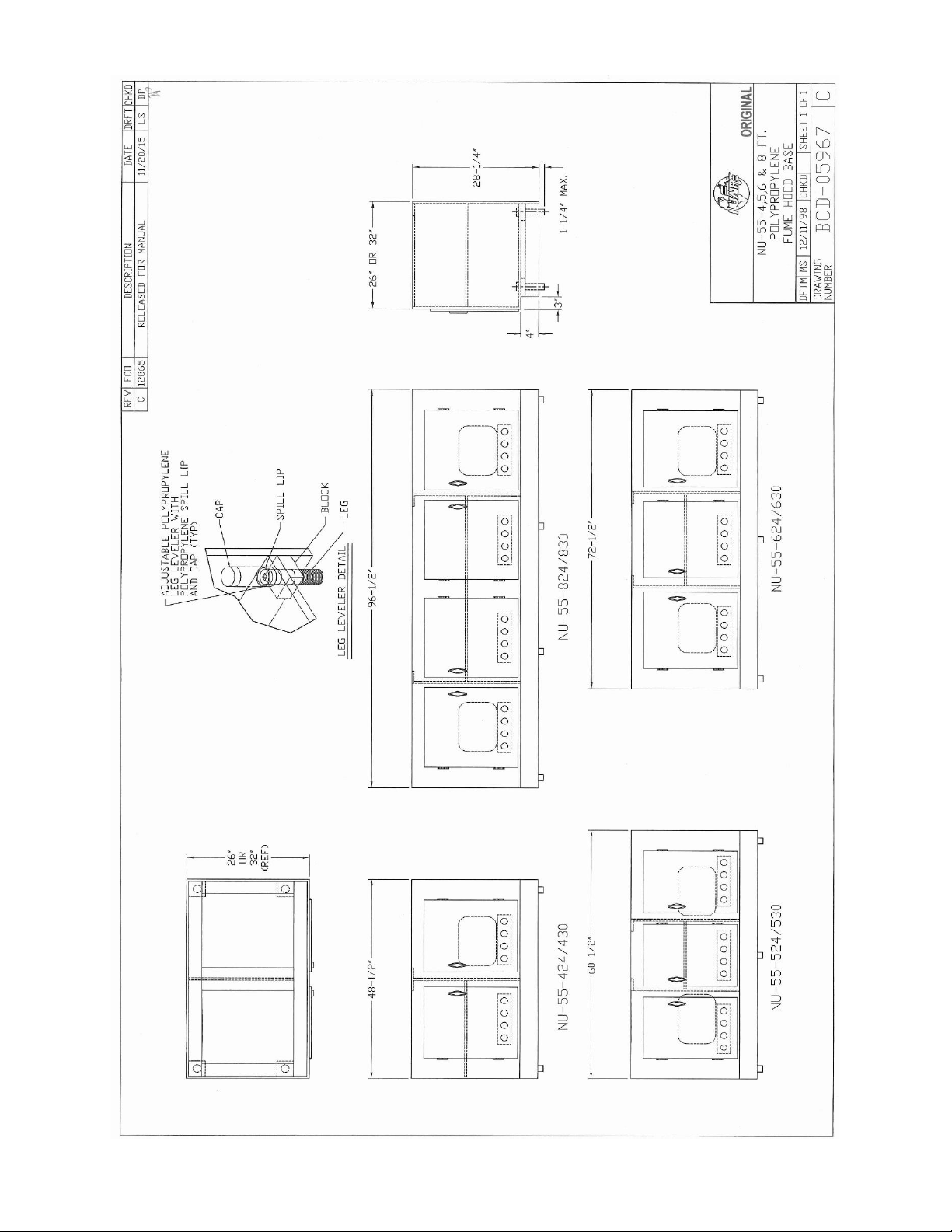
BCD-05967 ............................................................................... NU-55 Polypropylene Bases
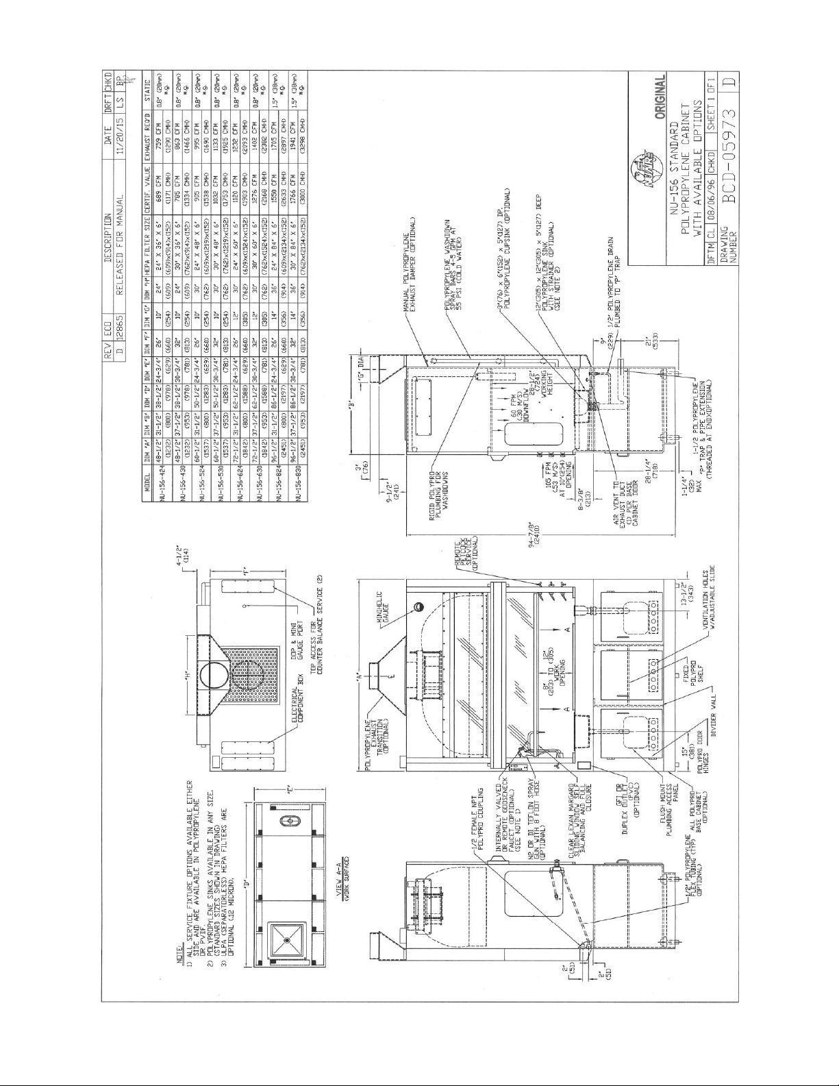
BCD-05973 ............................................................................... NU-156 Standard Bench Model W/Options
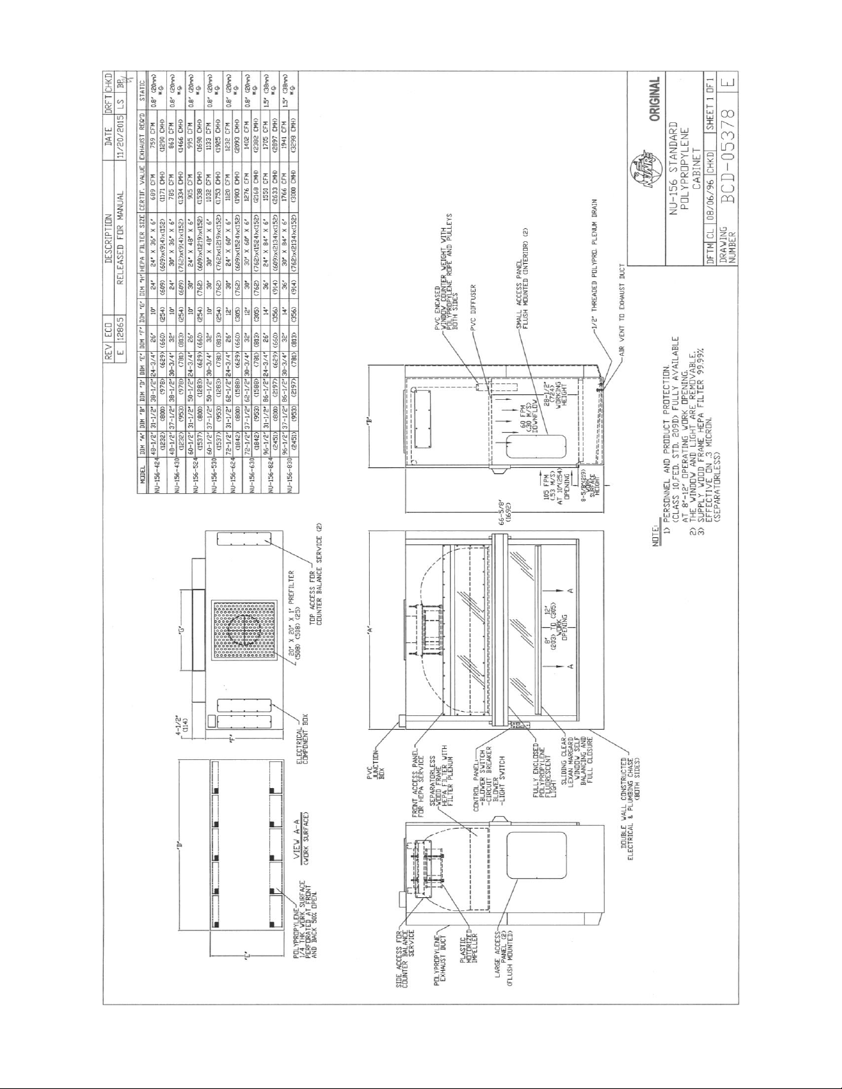
BCD-05378 ............................................................................... NU-156 Standard Bench Model
BCD-05974 ............................................................................... NU-156 Installation Assy.
BCD-05979 ............................................................................... NU-156 Filter Removal Procedure
BCD-05957 ............................................................................... Fume Hood /Base Cabinet Installation
BCD-05831 ............................................................................... NU-156 Electrical Schematic
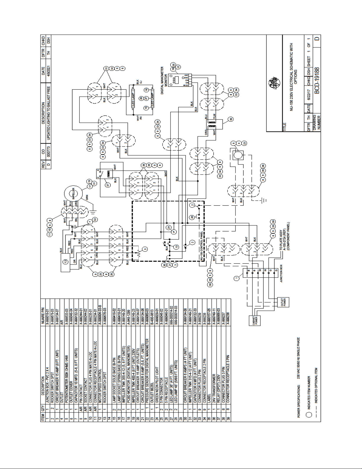
BCD-19188 ............................................................................... NU-156E Electrical Schematic
Page 4

OM0089 Page 4 of 39
April/2021
CONGRATULATIONS!
You have just purchased one of the finest all polypropylene FumeGard Vertical Laminar Flow Clean Air Fume Hoods available. With
proper care, maintenance and laboratory procedure, this Fume Hood will give you years of product protection from particulate
contaminants and personnel protection from particulate, gas and vapors as meeting the containmenmt performance requirements
of NSF/ANSI 49 and ASHRAE Standard 110. Please read this manual carefully to familiarize yourself with proper installation,
maintenance and operation of the Fume Hood.
Page 5

OM0089 Page 5 of 39
April/2021
FumeGard Vertical Laminar Flow
Clean Air Wet Process Fume Hood
(Total Exhaust)
Model NU-156/E Series
Manufactured By:
Nuaire, Inc. - Plymouth, Minnesota
1.0 General Information
1.1 Description
NuAire’s all Polypropylene Model NU-156/E FumeGard Vertical Laminar Flow Wet Process Fume Hood is a bench module
Fume Hood which utilizes the latest state-of-the-art technologies in laminar airflow design, materials and manufacturing
processes. The modular constructed Fume Hood can be used anywhere space permits where product (work-in-process)
and personnel protection are required for chemical research, microelectronics, semi-conductor design/development and/or
production assembly processes. Bench Fume Hoods consist of a single piece construction and can be placed on a customer
bench or on a special option polypropylene base provided for the Fume Hood. A significant number of design innovations
give the NuAire laminar flow equipment superior performance qualities in airflow, lighting, noise levels and vibration. In
addition, NuAire’s “Narrow Line Design” technique achieves excellent appearance and ruggedness through the use of large
modular components, reinforced construction techniques and contrasting color schemes.
The Model NU-156/E FumeGard Vertical Laminar Flow Clean Air Polypropylene Wet Process Fume Hood is a product
resulting from the development of the “laminar” flow principle, the application of environmental controls in the fields of
biological research or chemical containment and the necessity to provide a chemically inert and resistant work space. The
wet process fume hood, when used with proper laboratory technique, is an effective laboratory aid in obtaining optimum
control over product quality while reducing the potential for exposure of both product and personnel to airborne
particulate chemical agents as well as fumes and vapors generated as a result of work-in-progress operations.
The NU-156/E FumeGard has been designed and tested to the performance criteria as established by the NSF/ANSI 49 for
Biosafety Cabinets for personnel, product containment performance. In addition, the NU-156/E meets or exceeds ISO 5 air
quality conditions. The NU-156/E has been independently tested by Knutson Ventilation; Minneapolis, MN for its
containment properties (i.e. personnel protection) to ASHRAE Standard 110-2016 for Fume Hoods, with a Performance
Hood Rating of AM<0.1 (instrument’s limit of detection) when operating at a sash height of 10 inches (254mm).
1.2 Safety Instructions
These safety instructions describe the safety features of the FumeGard Model NU-156/E.
The Fume Hood has been manufactured using the latest technological developments and has been thoroughly tested
before delivery. However, the Fume Hood may present potential hazards if it is not installed and used as instructed for
its intended purpose or outside of operating parameters. Therefore, the following procedures must always be observed:
• The Fume Hood must be operated only by trained and authorized personnel.
• For any operation of this Fume Hood, the operator must prepare clear and concise written instructions for
operating and cleaning, utilizing applicable safety data sheets, plant hygiene guidelines, and technical regulations,
in particular.
o Which decontamination or deactivation measures are to be applied for the Fume Hood and accessories?
o Which protective measures apply while specific materials are used?
o Which measures are to be taken in the case of an accident?
• Repairs to the device must be carried out only by trained and authorized expert personnel.
• Keep these operating instructions close to the Fume Hood so that safety instructions and important information
are always accessible.
• Should you encounter problems that are not detailed adequately in the operating instructions, please contact your
NuAire Representative of NuAire technical Services.
Page 6
OM0089 Page 6 of 39
April/2021
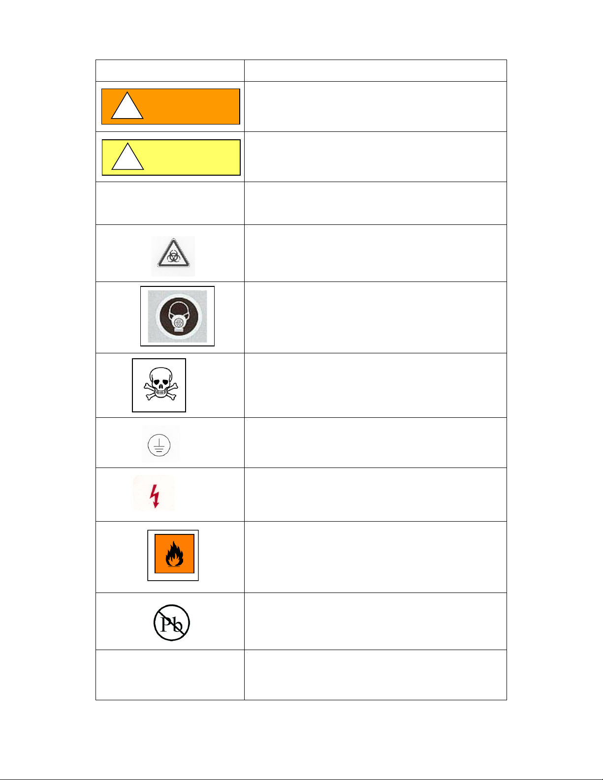
1.3 Explanation of Symbols
Symbol
Description
CAUTION
Safety alert symbol indicates a potentially hazardous
situation which, if not avoided, could result in death of
serious injury.
CAUTION
!
Safety alert symbol indicates a potentially hazardous
situation which, if not avoided, may result in minor or
moderate injury.
WARNING
!
Note: Used for important information
Biohazard
Hazardous Gases!
Personal Protection Equipment Required.
Chemical Hazard
Ground, Earth
Flammable Hazard
Potential electrical hazard,
only qualified person to access.
Lead Free
CAUTION used without the safety alert symbol
indicates a potentially hazardous situation which, if not
avoided, may result in property damage.
Page 7

OM0089 Page 7 of 39
April/2021
Page 8

OM0089 Page 8 of 39
April/2021
2.0 Model and Features
The NU-156/E FumeGard Vertical Laminar Flow Wet Process Fume Hood is manufactured in four standard widths:
4 ft., 5 ft., 6 ft. and 8 ft., with two standard work surface depths: 26” or 32”. (See also Specification Drawing BCD-05043.)
Dimensions
NU-156-4 ft.
NU-156-5 ft.
NU-156-6 ft.
NU-156-8 ft.
Overall Dimensions
Width (W)
Depth (D) includes
duct and light)
Height (H) includes
prefilter grill)
48 1/2”(1232mm)
35”/41”
(889mm)/(1041mm)
66-5/8”
(1692mm)
60 1/2”(1536mm)
35”/41”
(889mm)/(1041mm)
66-5/8”
(1692mm)
72 1/2”(1842mm)
35”/41”
(889mm)/(1041mm)
66-5/8”
(1692mm)
96 1/2”(2451mm)
35”/41”
(889mm)/(1041mm)
66-5/8”
(1692mm)
Work Area Dimensions
Width
Depth
Height
38 1/2”(978mm)
25 1/2”(648mm)
OR: 31 1/2”(800mm)
29”(737mm)
50 1/2”(1283mm)
25 1/2”(648mm)
OR:31 1/2”(800mm)
29” (737mm)
62 1/2”(1588mm)
25 1/2”(648mm)
OR:31 1/2”(800mm)
29” (737mm)
86 1/2”(2197mm)
25 1/2”(648mm)
OR: 31 1/2”(800mm)
29” (737mm)
2.1 Standard Features
*HEPEX Zero Leak Airflow System
*Standard HEPA Filter: Wood Frame Separatorless 99.99% Efficient on 0.3 Microns
*External LED Lighting
*Front Filter Removal
*Sliding View Screen: Fully Closing to 20” Open
*10-Inch (254mm) Work Access Opening at 100 LFPM (.51 m/s)
*Removable Solid Work Surface with Front and Rear Perforated Grills
*1/2-Inch Stress Relieved Seam Welded Polypropylene
*PVC Diffuser over Supply HEPA Filter
*Spill Trough Plenum under Work Surface
*Flush Mounted Interior and Exterior Plumbing Access Panels
*Plastic Motorized Impeller
2.2 Optional Features
*Magnehelic Gauge: For Supply Pressure
*Remote Controlled Polypropylene/PVDF Service Fixtures
*Duplex Electrical Outlet, Externally or Internally Mounted
*12” X 12” x 5” Polypropylene Sink With Strainer and “P” Trap
*Ground Fault Circuit Interrupter
*Polypropylene or PBF Kynar Hi-Purity Plumbing
*Cascade Rinse Tanks, Single to Triple Tanks with Nitrogen Inlets for Improved Scrubbing Action
*DI, N2 Teflon Spray Guns
*Exhaust Monitor Alarm
*Exhaust Blower Interlock with Alarm
*Exhaust Transition 10” to 14” Round; 1/4-Inch Polypropylene
*99.999% Efficient HEPA Filter on 0.12 Micron (ULPA)
*Fully Perforated (10% Open) Work Surface
*Vented Base Storage Cabinet
Page 9
OM0089 Page 9 of 39
April/2021
Page 10
OM0089 Page 10 of 39
April/2021
Page 11
OM0089 Page 11 of 39
April/2021
Page 12

OM0089 Page 12 of 39
April/2021
3.0 Warranty
Details regarding product warranties can be found in the published warranty data separate from this manual and included
within the data packet sent with the unit.
4.0 Shipments
NuAire takes every reasonable precaution to assure that your FumeGard Fume Hood arrives without damage. Motor carriers
are carefully selected and shipping cartons have been specially designed to insure your purchase. However, damage can occur
in any shipment and the following outlines the steps you should take on receipt of a NuAire FumeGard Fume Hood to be sure
that if damage has occurred, the proper claims and actions are taken immediately.
4.1 Damaged Shipments
4.1.1 Terms are factory, unless stated otherwise. Therefore, it is important to check each shipment before acceptance.
4.1.2 If there is visible damage, the material can be accepted after the driver makes a notation on the consignee's copy
of the freight bill. Then an inspection must be made to verify the claim against the carrier. This inspection is the
basis of your filing the claim against the carrier.
4.1.3 If concealed damage is found it is absolutely necessary to NOTIFY THE FREIGHT AGENT AT ONCE and request an
inspection. Without this inspection, the transportation company may not accept a claim for loss or damage. If the
carrier will not perform the inspection, an affidavit must be prepared stating that he was contacted on a certain
date and that he failed to comply with the request. This along with other papers in the customer's possession will
support the claim.
Page 13
OM0089 Page 13 of 39
April/2021
5.0 Installation Instructions
5.1 Location
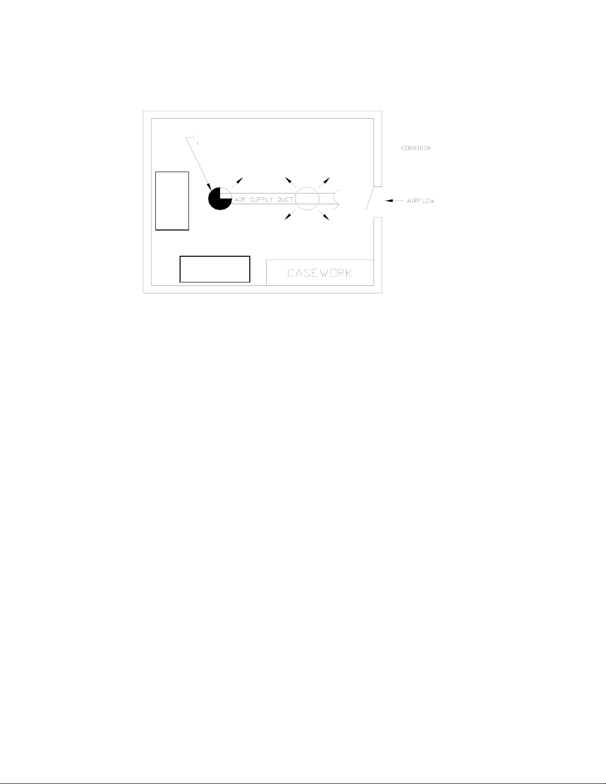
Within the laboratory, production process, etc., the ideal location for the Fume Hood is away from personnel traffic lanes,
air vents (in or out), doors and/or any other source of disruptive air currents.
If drafts or other disruptive air currents exceed the intake velocity of the Fume Hood through the access opening, the
potential exists for contaminated air to exit or enter the work surface area of the Fume Hood. It depends on the severity of
the air current. Remember, the FumeGard Fume Hood is no substitute for good laboratory technique. Supply makeup air
should be evenly diffused into the room at a rate not to exceed 75 LFPM (.38 m/s), and never “blasted” directly at the floor.
Where space permits, it is recommended to provide a clear 6-inch (152mm) area on each side of the Fume Hood for
maintenance purposes.
The electrical outlet into which the Fume Hood is connected should be readily accessible for maintenance purposes. Do not
position the Fume Hood to prevent access to the power cord. The power cord plug serves as the disconnect and should
remain readily accessible. If the outlet is inaccessible, such as a conduit (hardwired) connection, then an appropriate
warning label should be applied near the Fume Hoods on/off switch, to indicate the circuit breaker on the power
distribution panel to be used.
More than any other type of Fume Hood, the NU-156/E requires careful site planning and preparation, due to the total
exhaust nature of the Fume Hood. Proper sizing of the exhaust and supply systems are critical to the successful installation
of the Fume Hood. In addition, the Fume Hood provides for the choice of makeup air for the supply (downflow air). The
following are airflow requirements:
Supply Air
Inflow
Exhaust Air **
NU-156-424/E
409 CFM (695 CMH)
280 CFM (476 CMH)
759 CFM (1291 CMH)*
NU-156-524/E
536 CFM (511 CMH)
369 CFM (627 CMH)
995 CFM (1690 CMH)*
NU-156-624/E
664 CFM (1128 CMH)
456 CFM (775 CMH)
1232 CFM (2093 CMH)*
NU-156-824/E
919 CFM (1561 CMH)
631 CFM (1072 CMH)
1705 CFM (2897 CMH)*
NU-156-430/E
505 CFM (858 CMH)
280 CFM (476 CMH)
863 CFM (1466 CMH)*
NU-156-530/E
663 CFM (1126 CMH)
369 CFM (627 CMH)
1133 CFM (1925 CMH)*
NU-156-630/E
820 CFM (1393 CMH)
456 CFM (775 CMH)
1402 CFM (2382 CMH)*
NU-156-830/E
1135 CFM (1928 CMH)
631 CFM (1072 CMH)
1941 CFM (3298 CMH)*
*CFM exhaust at 0.8 inches (20mm) w.g. negative measured at the rectangular exhaust duct of the Fume Hood for 4, 5 and
6 ft. Fume Hoods. CFM exhaust at 1.5 inches (38mm) w.g. negative measured at the rectangular exhaust duct of the Fume
Hood for 8 ft. Fume Hoods.
**Concurrent Balance Value is determined by a duct traverse measurement method taken a minimum of 7.5 duct
diameters downstream of the direct connected LFBSC at its nominal setpoint calibrated using the primary DIM method and
capture hood removed. These values shall be used for design and balance exhaust/supply HVAC requirements.
FUMEGARD
LOCATION
FUMEGARD
LOCATION
VENTALATION REGISTER
(BLOCKED WHEN FACING FUME HOOD)
Page 14
OM0089 Page 14 of 39
April/2021
Page 15
OM0089 Page 15 of 39
April/2021
Page 16

OM0089 Page 16 of 39
April/2021
5.2 Set-Up Instructions
Remove outer shipping protection (carton or crating). The Fume Hood is banded to the base skid and it is usually the best
procedure to leave the skid in place until the Fume Hood is located in its approximate position to facilitate ease in handling.
It can then be removed from the skid by removing the banding holding the Fume Hood to the skid.
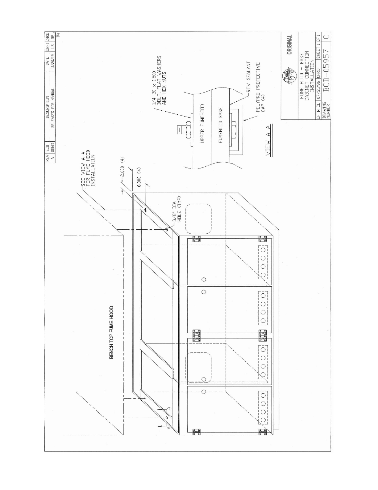
5.2.1 Base Cabinet Assembly (BCD-05957)
The base cabinet is shipped on a separate skid if accompanied with the Fume Hood. Remove the banding holding
the base cabinet to the base skid. Lift the base cabinet from the skid and place on the floor. Now lift the Fume
Hood on top of the base cabinet and bolt the base cabinet to the Fume Hood using (4) 1/4-20 x 1-1/2” bolts and
washers provided for the attachment process.
5.2.2 Leveling
Using a level placed on the work tray, adjust the leg levelers, first, end-to-end then front to back. The leg levelers
located on the floor of the base cabinet are adjusted using a 3/8” drive socket and rotating to raise or lower as
necessary.
5.2.3 Bench Installation
Place the Fume Hood on the bench. Using RTV caulk, seal all around the base of the Fume Hood and the bench.
This provides a tight seal to prevent bench spills from migrating under the Fume Hood.
5.2.4 Electrical Services
The NU-156/E all Polypropylene Wet Process Fume Hood may be "hardwired" (optional) or plugged into an outlet
with protective earthing connection with the standard power cord. The Fume Hood requires 115/230VAC,
50/60Hz single phase (correct rating varies per Fume Hood size, reference Electrical/Environmental Requirements).
It is recommended that power to the Fume Hood, whether hardwired or plug connected, be on its own branch
circuit, protected with a circuit breaker at the distribution panel near the Fume Hood.
5.2.5 Plumbing Services
Remote controlled polypropylene needle-valve plumbing fixtures are provided within the side walls of the Fume
Hood with control handles located external on the face of the Fume Hood. The type of service is specified by the
colored-wall petcock (i.e. air, gas, Vacuum, nitrogen, etc.) Service outlets within the interior are designed for hose
connections with ten serrations.
All plumbing services are plumbed within the right or left chase with 1/2 inch flexible polypropylene tubing and
compression fittings. Water service plumbing lines are rated at a maximum of 60 PSI (4.5 Bars) as tested at NuAire
before shipment. Air and gas lines are tested at a 90 PSI (6.75 Bars) maximum.
All plumbing terminates at the rear of the Fume Hood (for customer hook-up) with 1/2 inch female NPT
polypropylene couplings.
All sinks are plumbed with 1 1/2 inch Polypropylene “P” trap and piping that exits out the rear of Fume Hood in the
storage area. A rear access panel is provided for drain connection.
Connection to plant utilities should be made with proper materials for the individual service and according to
national and/or local codes. It is not recommended that flammable gases be used in the Fume Hood unless flame
retardant Polypropylene is purchased; however, if flammable gas is used, emergency shutoff valves should be
located in an accessible area external to the Fume Hood. Observe all labels pertaining to the type of services and
operating pressure.
Page 17

OM0089 Page 17 of 39
April/2021
5.2.6 Exhaust/Supply Duct Installation Guidelines
The exhaust/supply systems must provide conditions similar to that under which the Fume Hood was certified to
meet its stated performance. The following guidelines should be observed when installing exhaust/supply air duct
work of either existing plant exhaust systems, or a new exhaust system.
1) Adequate room air inflow to replace exhausted air.
Air diffusion rate not to exceed velocity of 105 LFPM (.53 m/s).
MAKEUP AIR REQUIREMENTS
Without Supply Duct
NU-156-424/E
759 CFM (1290 CMH)
NU-156-524/E
995 CFM (1690 CMH)
NU-156-624/E
1232 CFM (2093 CMH)
NU-156-824/E
1705 CFM (2897 CMH)
NU-156-430/E
863 CFM (1466 CMH)
NU-156-530/E
1133 CFM (1925 CMH)
NU-156-630/E
1402 CFM (2382 CMH)
NU-156-830/E
1941 CFM (3298 CMH)
2) Adequate plant exhaust system capability.
The exhaust system is usually adequate if it can provide the rated exhaust flow at 1.0 inches water gauge
negative.
3) Adequate supply air capability (if used).
The supply air system is usually adequate if it can provide the rated supply air at 0.0 inches water gauge
positive.
4) All duct losses must be considered in selecting the exhaust blower, for a new exhaust system.
(i.e. duct diameter, length and number of elbows)
5) All duct work should be securely anchored to the building construction in a manner to be free from
vibration and swaying under all conditions of operation.
6) Sheet metal gauges and seams should be in accordance with the current edition of the ASHRAE guide. A
minimum of 24 gauge is required to prevent duct collapse due to high static pressure conditions,
required.
7) All duct work should be maintained at a negative pressure within the building.
(i.e. externally located exhaust blower)
8) The exhaust blower and duct work should be a sealed system, properly vented to the atmosphere to
disperse exhausted air.
9) The exhaust duct should be dampered. Dampers should be installed with a locking quadrant with
markings to indicate damper position. A Polypropylene damper system is available and is located in the
upper duct extension.
5.2.7 Final Assembly and Inspection
Remove any remaining packaging materials, tape. etc. along with the window sash and counter balance blocking
with in the right and left side service chase. Inspect all fume hood surfaces, service connections and sash assembly
operation, rope and counter balance. Lastly, the exterior surfaces and viewing window are easily cleaned with any
mild household detergent using a soft cloth. Harsh chemicals, solvent-type cleansers and abrasive cleaners should
not be used. Do not attempt to clean the HEPA filter media. Fume Hood interior walls or work surfaces are easily
cleaned with any household detergent using a soft cloth. The work surface is removable for access to the sloped
drain plenum area for cleaning. The interior should be thoroughly cleaned prior to use. A solution of 70% isopropyl
alcohol is suitable for a final cleaning process.
Page 18

OM0089 Page 18 of 39
April/2021
5.3 Testing Methods and Equipment
After installation and prior to use, NuAire recommends that the Vertical Laminar Flow Clean Air Polypropylene Wet Process
Fume Hood be tested or commissioned to factory standards. As part of testing, the certifier should go through the following
initial checklist to assure all aspects of the installation are complete and ready for testing.
• Review product installation
- Exhaust connection
- Damper valve installed correctly
- Base cabinet level
• Perform certification
- At a minimum, the following tests should be performed:
• HEPA filter leak test
• Downflow velocity test
• Inflow velocity test
• Airflow smoke patterns
• Site installation assessment tests
The testing methods and equipment required are specified on the factory inspection report included with this manual (see
insert in back cover).
NOTE: IT IS RECOMMENDED THAT THESE TESTS BE PERFORMED BY A QUALIFIED TECHNICIAN WHO IS FAMILIAR
WITH THE METHODS AND PROCEDURES FOR TESTING BIOSAFETY CABINETS AND FUME HOODS (SEE
INSERT).
NOTE: AFTER THE INITIAL CERTIFICATION, NUAIRE RECOMMENDS THAT THE CABINET BE RECERTIFIED AT A
MINIMUM OF AN ANNUAL BASIS AND AFTER EVERY FILTER CHANGE, MAINTENANCE ACTION, OR ANY
TIME THE OPERATOR FEELS IT IS NECESSARY.
NOTE: The Flowgard Fume Hood, filters and seals provide premium performance. Quality control in both design and
manufacturing insure superior reliability; however, protection to both product and operator is so vital that
certification to the performance requirements should be accomplished as stated to insure personnel safety as
established by the factory standards.
Page 19

OM0089 Page 19 of 39
April/2021
6.0 Operating the NU-156
6.1 Operator Controls and Indicators
The following is a description of the controls and indicators on the instrument control panel.
6.1.1 Blower Switch
The blower switch applies power to the internal blower when in the ON position.
6.1.2 Indicator Light
A green neon indicator light is located above the blower on/off switch and lights when power is applied to the
blower. The lamp is rated for 20,000 hours continuous duty.
6.1.3 Circuit Breaker - Blower
The blower is protected with a circuit breaker. The circuit breaker in conjunction with the blower’s thermal
protector is designed to open under locked rotor or half-wave power conditions. Should the circuit breaker open
(pop-out button will appear), merely press to reset. If the circuit breaker continually opens, a failure has occurred
in the motor or solid-state speed controller. Consult a qualified repair technician or NuAire, Inc. for replacement.
6.1.4 Light switch
The light switch provides on/off control for the LED light.
6.1.5 Outlet Switch (Optional)
This switch provides on/off control for the line power available in the outlet within the interior of the Fume Hood
or located in either outside sidewall of the base cabinet.
6.1.6 Circuit Breaker - Outlets (Optional)
The outlet located on the Fume Hood is protected with a separate circuit breaker. The circuit breaker may trip at
110% of load rating, but will trip at 145% of load rating in less than 2 hours. Should the circuit breaker open
(pop-out button will appear), unplug the appliance plugged into the outlet and merely depress the pop-out button
to reset.
NOTE: If the outlet circuit breaker is not present in your model and the outlet circuit has been specifically wired
as a separate circuit, the outlet rating is dependent on the branch circuit, circuit breaker at the power
distribution panel.
6.1.7 Airflow Control
The operating downflow within the Fume Hood (i.e. 60 LFPM (.30 m/s) is controlled by a potentiometer located in
the instrument control panel. The potentiometer controls the operating voltage applied to the blower. The
potentiometer is adjustable over 270 degrees with a slotted screwdriver, which varies the applied voltage.
THIS ADJUSTMENT SHOULD ONLY BE MADE BY A QUALIFIED TECHNICIAN.
6.1.8 Minihelic Gauge (Optional)
If the unit is equipped with a minihelic gauge, it will display the static pressure within the pressure plenum
supplying the downflow HEPA filter. The gauge is calibrated in “inches of water gauge” pressure. As the HEPA
filter loads with particulate matter, the amount of static pressure will increase, giving an indication of the “health”
of the Fume Hood. From the initial pressure reading each 0.1” w.g. increment, the Fume Hood airflow should be
checked by a qualified technician, unless certified on a yearly (or sooner) basis.
The minihelic gauge is optionally available and is mounted on the upper right front of the Fume Hood. The
minihelic gauge is connected with PVC tubing to the filter plenum.
Page 20

OM0089 Page 20 of 39
April/2021
6.1.9 Exhaust Digital Monitor
General
The exhaust digital monitor uses an integrated digital pressure transducer to monitor negative pressure. The
monitor indicates through both a segment display and LED’s. The segment display is green and operates to
+ 0.01”w.g. sensitivity. The LED’s indicate acceptable pressure (green), caution or near alarm points to
within 0.005”w.g. (yellow) or alarm condition (red).
The monitor starts when the blower to the NU-156 is switched on. Upon start up, all segments displays, and
LED’s will light and a short audible alarm will sound to indicate a properly functioning monitor. During the
next 4 minutes, the segment display will indicate dashes and green LED will blink during the warm-up
period. Once the 4-minute warm-up period is complete, the monitor will measure and display the current
exhaust system. If the monitor is not functioning properly, the green, yellow and red LED’s will blink to
indicate an error.
The monitor is powered by a 115V outlet within the NU-156. The monitor also has alarm contacts, COM,
and NC that will disable the NU-156 supply blower if the exhaust static pressure falls within the alarm
conditions of the digital monitor. All users’ interaction is accomplished through the arrow and reset keys. It
is recommended that the monitor be calibrated during the certification process.
Nominal Pressure Calibration
The exhaust digital monitor is factory calibrated to the nominal exhaust system static pressure. This is
accomplished through an offset calibration procedure. To accomplish, perform the following once the
Isolator has been certified to its proper airflow and the monitor is through the warm-up period.
• Press and hold [] and [] arrow key simultaneously for 3 seconds until the red LED
blinks and the display alternates “In” and a pressure value.
Use [] and [] arrow keys to adjust the display value to match the pressure in the exhaust duct.
• Press [RESET’ key to enter the nominal pressure value (red LED will stop blinking and
display will indicate pressure value).
High/Low Alarm Setpoint Calibration
The exhaust digital monitor is factory calibrated to a high/low alarm setpoint of +.2” w.g. / -.50” w.g. from
the nominal exhaust system static pressure setpoint. To verify or to change the alarm setpoints, perform
the following procedure.
• Press and hold either [] key for high alarm or [] key for low alarm for 3 seconds until the red
LED blinks and the display alternates either “Hi” or “Lo” and a pressure value.
• Use [] and [] arrow keys to adjust the display value desired.
• Press [RESET] key to enter the alarm setpoint value.
Audible alarm
The audible alarm should be activated whenever the pressure reaches the high or low alarm setpoint.
However, once the alarm pressure is reached, it must stay on the alarm limit for 5 seconds consistently or it
will not recognize it as an alarm. If at any time, the pressure returns to acceptable limits, the alarm would
be reset and silenced. Once the 5 second period of constant alarm is present, the audible should sound for
30 seconds, then ring back 1 second every 10 seconds. If the [RESET] key is pressed, the alarm should be
silenced for 5 minutes, then continue to ring back for 1 second every 10.
Page 21

OM0089 Page 21 of 39
April/2021
6.2 Operating Guidelines
The intent herein is to present general operational guidelines that will aid in the use of the Laminar Flow Wet Process Fume
Hood to control airborne contaminants of low to moderate risk as stated in Technical Report No. FPS 56500000001
prepared by Dow Chemical U.S.A. for the National Cancer Institute.
6.2.1 Procedure protocols defined in terms of the barrier or control concepts unique to the NU-156 must be developed
in order to obtain the maximum potential for safety and protection. The preplanning necessary to develop these
protocols is based on several fundamental considerations, each of which will contribute to optimum benefits from
the equipment:
a. Minimize disruption of “air curtain”
b. Minimize room activity
c. Utilize unidirectional air flow
d. Adequately diffused makeup air
e. Minimize blockage of front/rear inlet grills
f. Minimize overcrowding of work surface
6.2.2 Minimize Penetration of “Air Curtain”
The minimum number of items necessary should be placed into the Fume Hood to prevent overloading, but the
work should also be planned to minimize the number of times an operator’s hands and arms must enter and leave
the air curtain at the open face. The ideal situation is to have everything needed for the complete procedure
placed in the hood before starting, so that nothing need pass in or out through the air barrier at the face until the
procedure is completed. This is especially important in working with moderate risk agents.
Unnecessary raising of the hands inside the Fume Hood above the level of the work opening should be avoided.
This presents an inclined plane from hands to elbows along which the downflow of air may run, to and possibly
out, the open face. When withdrawing hands from the Fume Hood, never use horizontal sweeping movements.
Always use motions parallel to the inflow velocity - straight in, straight out.
NOTE: When working with agents of lower risk, it is not as important for all materials to be placed in the Fume
Hood before starting, or for the procedure to be completely finished before materials are removed. Also,
the time period for a unit of work may be continued over a more extended period during which entries
and withdrawals from the Fume Hood may be made.
6.2.3 Minimize Room Activity
Activity in the room itself should be held to a minimum. Unnecessary activity may create disruptive air currents as
well as interfere with the work of the operator. A person walking past the front of a Fume Hood can cause draft
velocities up to 175 FPM (.89 m/s), which are sufficient to disrupt the air balance of the laminar flow unit.
6.2.4 Utilize Unidirectional Air Flow
The operator must keep two important facts in mind:
(1) The air, as supplied to the work area through filters from the top, is contaminant free and
(2) Airborne contamination generated in the work area is controlled by the unidirectional flow of parallel air
streams in a top-to-bottom direction.
A solid object placed in a laminar air stream will disrupt the parallel flow and consequently, the capability of
controlling lateral movement of airborne particulates. A cone of turbulence extends below the object and
laminarity of the air stream is not regained until a point is reached downstream, approximately equal to three to
six times the diameter of the object. Within the parameters of this cone, particles may be carried laterally by
multidirectional eddy currents.
6.2.5 Adequately Diffused Makeup Air must be employed in order to avoid disruptive air currents that will penetrate
the work access opening, causing contaminated interior downflow air to escape or inflow air to penetrate the work
surface, contaminating work in process. Makeup air must be diffused at no greater than 100 LFPM (.51 m/s) as
measured 6 inches (152mm) below the diffuser. If this cannot be achieved, then makeup air must be supplied near
the inlet air to the blower above the Fume Hood. Smoke flow tests, see Section 4.6, must result in all smoke being
contained, with no refluxing or drift within the interior. On units with sinks, some drift of the interior downflow
will be experienced near the sink, toward the center of the Fume Hood. These flow characteristics must be kept in
mind when locating “clean” and “dirty” work in process.
Page 22

OM0089 Page 22 of 39
April/2021
6.2.6 Minimize Blockage of Front/Rear Inlet Grills
The personnel and product protection afforded by the NU-156 demands that the front and rear grills be kept free
of all materials. The tests per NSF/ANSI 49 and ASHRAE110-2016 to determine the level of personnel and product
protection are conducted with the grills unblocked.
Blocking the inlet grill will most assuredly result in a loss of personnel protection. Arms should be kept above the
inlet grill (i.e. this is the reason for the one-inch airfoil lip). Lab coats should be tight fitting and not permit blocking
of the suction inlet grill.
Blocking of the rear grill will alter the airflow pattern which could affect cross contamination of work in process.
Excessive blocking of the rear grill will force more air toward the front grill which will lower the personnel
protection afforded by the Fume Hood, permitting potentially contaminated downflow air to escape the work
access opening.
NOTE: With a fully perforated work surface it is not as important to concern oneself with blocking airflow
patterns created by the rear grill. Overcrowding the work surface should be avoided, however, since the
perforated work surface does not have a defined rear grill.
6.3 Ergonomics
Ergonomics, the study or accommodation of work practices is extremely important for proper cabinet usage and user
health and safety. An evaluation of normal work practices should be performed with each user when working in a cabinet.
Evaluation criteria should be at a minimum:
a. Proper user posture
b. Effective work zone layout for work practice
c. Vision or sightlines
For each of the above evaluation criterion, several work aids may be supplied to accommodate the user.
• Ergonomic chair - A six-way articulating seat and back control for personalized adjustment to assure proper user
posture. Be sure feet are resting on the floor, chair foot support or foot rest. Also be sure back is fully supported
with proper chair adjustments.
• Forearm/elbow support - The cabinet is provided with a non-metallic forearm support on the work access opening.
Periodic mini-breaks during work practice should be taken resting forearm to avoid stress and fatigue. Elbow rests
that can provide support for particular work practices, such as pipetting are optional. Also available as an option,
closed cell foam disposable forearm pads to reduce pressure points and add comfort.
• Effective workzone layout - Always prepare your work procedure to minimize reach to avoid neck and shoulder
stress and fatigue. Rotating tables used to maximum workzone and minimize reach are optional.
• Vision and sightline - Always prepare your work procedure to eliminate glare and bright reflections on the window.
Keep your window clean and sightlines clear to your effective workzone.
Page 23

OM0089 Page 23 of 39
April/2021
7.0 General Maintenance
All maintenance actions on this equipment must be performed by a qualified
technician who is familiar with the proper maintenance procedures required
for this equipment. This includes certification, inspection as well as repair.
The prefilter replacement internal depends on the contaminant (large particles or lint) in the room - a typical period is every
three months. NuAire does, however, recommend that the FumeGard have the integrity of the HEPA filters verified by a
qualified technician after the unit has been initially installed. Thereafter, certification should be performed on an annual basis,
or whenever the operator has reason to believe it necessary, especially if the Fume Hood has been moved to a new location, or
the magnehelic gauge has increased by 0.1” w.g. (2.5mm w.g.).
7.1 LED Lamp Replacement
Two LED lamps are sealed external to the Fume Hood to aid maintenance and minimize heat buildup within the Fume
Hood. The life rating of the lamp is 9000 hours based on three-hour burning cycles.
To replace a lamp it is necessary to remove the lamp fixture assembly.
1. Switch Fume Hood light switch off and remove the four front flat head screws.
2. With the help of another person to support the fixture, disconnect the fixture connector on the left end so the
entire fixture can be laid on a bench. The lamps are sealed behind a 1/8 inch (3mm) thick Lexan cover. Remove
the 1/4-20 screws that secure the cover to the fixture.
3. After the lamps are replaced reverse the procedure for assembly.
4. When replacing the light fixture, be sure to tuck the electrical wiring back into the holes (i.e. Fume Hood interior),
preventing unsightly wires from being exposed.
7.2 Supply Filter/Motor Replacement
The supply HEPA filter under normal usage and barring an accident (a puncture) do not need replacement until the supply
volume cannot be maintained. This may permit the supply average velocity to be as low as 55 LFPM (.28 m/s), as long as no
point falls below 20 percent of the average.
The supply filter for the FumeGard employs NuAire’s HEPEX system.
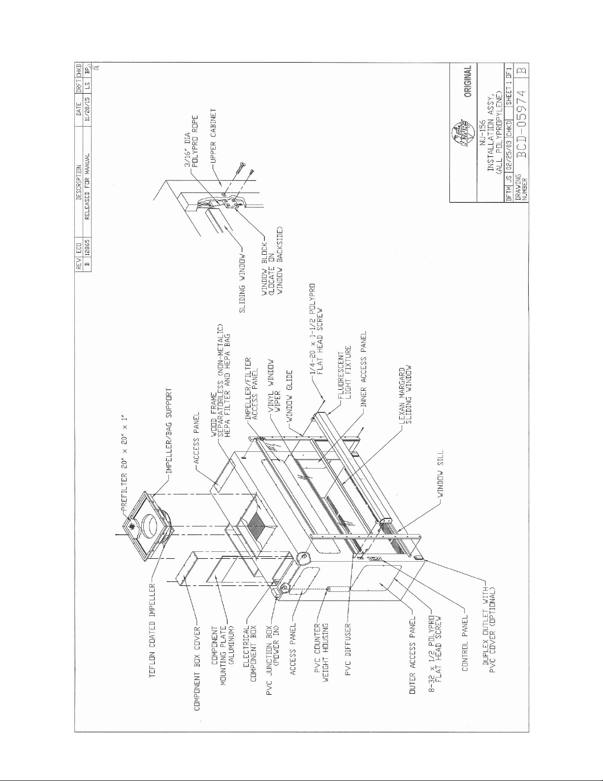
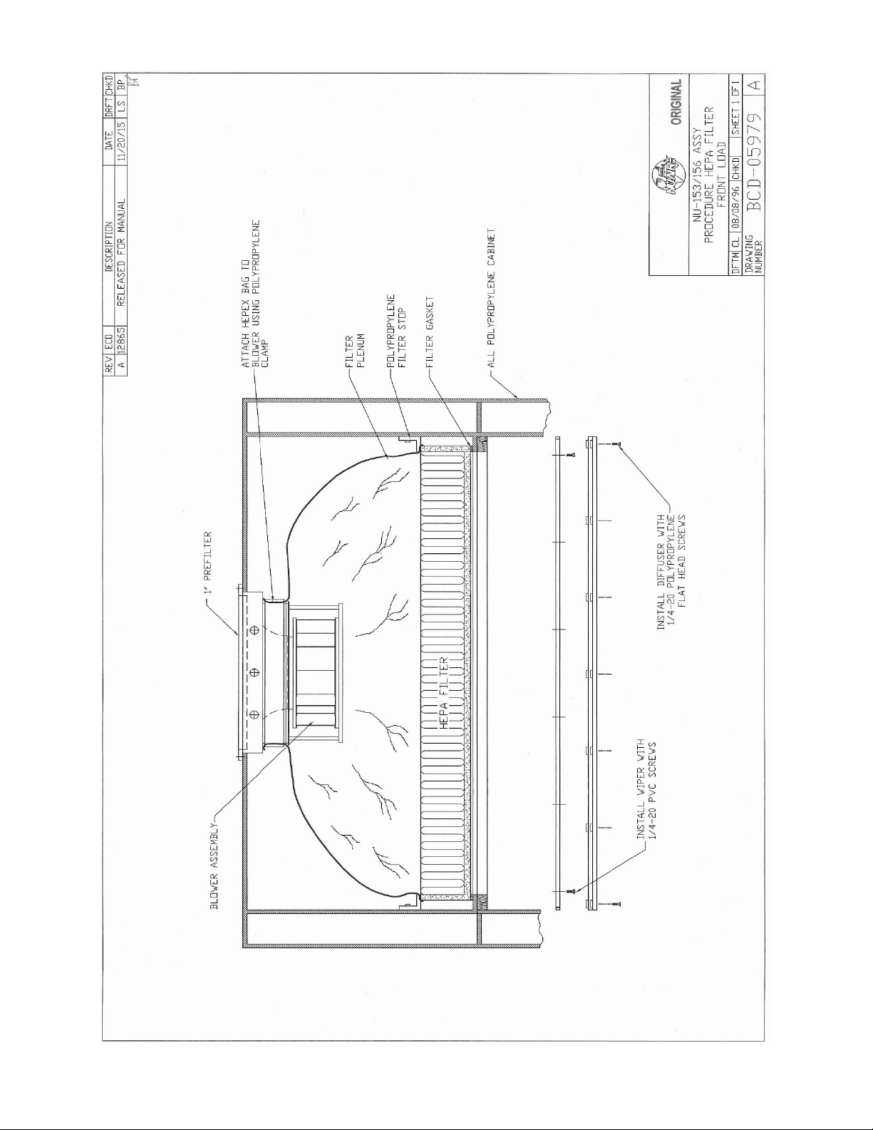
7.2.1 Supply Filter Replacement (Drawing BCD-05979)
Disconnect electrical power from the unit before attempting any
maintenance action.
Step 1: Remove the front access panel on upper Fume Hood to gain access to the HEPA filter and blower plenum
connection.
Step 2: Remove the Polypropylene band clamp holding the flexible plenum to the blower assembly.
NOTE: The blower assembly has been gasketed with double sticky back gasket which must be replaced
when installing a new filter.
Step 3: For ease of filter removal, remove the diffuser from inside the work zone. Remove the Polypropylene 1/4
- 20 flat head screws holding the diffuser in place. The diffuser also houses the vinyl wiper for the
window, which does not require removal.
Step 4: Before removing the HEPA filter, remove filter stops holding down the filter. It is the best procedure to
use two people to remove and replace the HEPA filter. Note that the filter is cradled in sponge rubber
and may require gentle tugging to gain release.
Step 5: To install the supply HEPA filter, simply reverse the procedure outlines in the steps above.
CAUTION
!
CAUTION
!
Page 24

OM0089 Page 24 of 39
April/2021
7.2.2 Blower Removal
Step 1: Disconnect electrical connections to the blower. A four-pin quick disconnect connector has been
provided for this purpose. It is recommended that the blower be removed as a single unit mounted on
the subassembly plate. Remove the (4) 1/4-20 x 1/2 bolts under the subassembly plate that connects
with the Teflon coated support posts. The plate and blower can be removed through the front access
panel.
Step 2: Replace the blower exactly as originally installed, paying particular attention to the correct electrical
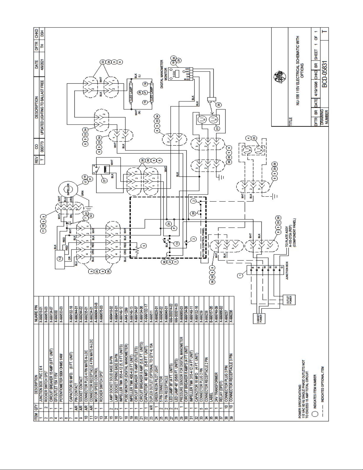
connections, see electrical schematic.
The following color coding has been established by NuAire:
Wire #
Definition
Color Code
1
Neutral
White
2
Hot (To Triac)
Black
5
Capacitor
Brown
7.3 Airflow Adjustments
The NU-156 airflow calibration consists of internal and external adjustments to balance the airflow within the Fume Hood
and the calibration of the airflow monitor probes. THIS WORK SHOULD BE DONE ONLY BY A QUALIFIED TECHNICIAN WHO
CAN MEASURE THE AIRFLOW FROM THE FILTERS WITH A SUITABLE VELOMETER. NuAire provides one internal adjustment
to balance the supply airflow within the Fume Hood. This is: Blower speed adjustment via control system.
The blower speed control system adjusts the Fume Hood’s supply volume of airflow while the customer supplied exhaust
system controls the exhaust volume of airflow.
The Fume Hood is considered to be certifiable if the following airflow measurements are present:
a. Downflow average: 60 LFPM +5 LFPM (.30 m/s +.025 m/s).
b. Inflow average: 105 LFPM +5 LFPM (.53 m/s +.025 m/s) using the direct inflow measurement method.
The following procedure should be used to measure the Fume Hood flow, in the order specified in the subsequent sections.
7.3.1 Total Flow Reference
The first step is to determine the total flow as a reference available to the Fume Hood, in order to evaluate the
proper installation (capability of the exhaust system.) The exhaust system is adequate if it can provide the
required static pressure at the Fume Hood’s rated maximum flow.
The total flow measurement procedure can be found in Table 7.1. If necessary, adjust the exhaust system to
achieve the correct exhaust volume. Use Table 7.0 to relate downflow and inflow volumes and corresponding
average airflow velocities. Note the internal motor/blower is turned off during the total flow measurement.
7.3.2 Determine Downflow Average
The procedure for determining the downflow average velocity is shown in Table 7.1. NuAire provides one
adjustment to balance the downflow within the Fume Hood, the motor speed adjustment. The downflow is
considered to be certifiable if the following measurements are present.
NOTE: NuAire employs a permanent split capacitor motorized blower which, due to its physical properties, will
automatically increase RPM as the applied load to the blower increases (i.e. the static pressure increases
due to HEPA filter loading.) This results in the capacity to automatically handle a 60 percent increase in
static pressure across the HEPA filter with no more than 10% drop in total flow (CFM). Therefore only a
moderate motor speed adjustment may be required on an annual certification basis.
7.3.3 Determine Work Access Inflow Velocity Average
The procedure to determine average inflow velocity is shown in Table 7.1. Once the average downflow velocity is
set, average inflow velocity is measured using a Direct Inflow Reading Instrument (DIM) and adjusting the exhaust
volume until the target value is achieved.
Page 25

OM0089 Page 25 of 39
April/2021
7.4 Filter Integrity Checks
In order to check filter and filter seal integrity, the HEPA filter media and seals must be directly accessible by measuring
instrument. The challenge material (i.e. PAO) should be supplied over the supply inlet for the supply filter and in the rear
center of the workzone over the intake slots for the exhaust filter. The upstream challenge port is located on top of the
Fume Hood.
A PVC diffuser plate, placed below the supply HEPA to protect the filter during normal usage as well as diffuse (even out)
the downflow, may be removed as follows.
The PVC diffuser is secured to the Fume Hood top by 1/4 - 20 Polypropylene screws located immediately behind the front
viewing window and along the rear and sidewalls. After removing the screws, lower the diffuser and remove from work
zone. Note that the diffuser has fixed spacers to allow clean air to feed down along side walls, back and front window to
force any stagnant particles through the perforated grills and out the exhaust duct. Also note the front of the diffuser
sandwiches a vinyl window wiper to contain air leakage above the diffuser.
Once the HEPA filter media and seals are exposed, the media and seals are scanned with a photometer at a traverse rate no
greater than 10 ft. per minute for leaks not to exceed 0.01% of upstream (challenged) concentration.
7.5 Airflow Smoke Pattern Test
The airflow smoke pattern test is performed using a smoke source (i.e. smoke tubes) in and around the cabinet workzone
and access opening to determine a visual representation of the cabinet’s containment performance. To perform the test,
the smoke source should be passed through the following areas:
A smoke source shall be passed:
1. From one end of the cabinet to the other, along the center line of the work surface, at a height of 4 inches
(102mm) above the top of the access opening.
2. From one end of the cabinet to the other, 1 inch (25mm) just inside the view screen, at a height 6 inches
(152mm) above the top of the access opening.
3. Along the edges of the entire perimeter of the work opening approximately 1.5 inches (38mm) outside the
cabinet, with particular attention paid to corners and vertical edges.
4. 2 inches (51mm) from the sides up inside of the window at the side channel seals, and along inside of the
cabinet along the top of the work area or immediately below the wiper gasket.
The criteria used to evaluate the smoke patterns is the following:
1. The smoke inside the cabinet shall show smooth downward flow with no dead spots or reflux.
2. No smoke shall escape from inside the cabinet.
3. No smoke refluxes out of the cabinet once drawn in, nor does smoke billow over the worksurface or penetrate
onto it.
4. No smoke shall escape from the cabinet.
7.6 Preventative Maintenance
The Fume Hood preventative maintenance inspection procedures should be performed annually during the certification
and consist of a physical examination of the work zone interior condition and cleanliness. Sash operation and condition,
rope, counter balance, light operation and service fixture ware and function. Inspection results should be recorded with
the certification results.
Page 26

OM0089 Page 26 of 39
April/2021
TABLE 7.0
CERTIFICATION VALUES
The following are recommended minimum/maximum Fume Hood airflow setpoints in order to maintain the Hood
Performance rating for personnel protection. NuAire recommends, however, operation at the stated average flow
for ease of maintenance and annual certification.
Model
Parameter
Minimum
Acceptable Flow
Stated
Average Flow
Maximum
Acceptable Flow
NU-156-424
1. Inflow Avg. Velocity
2. Inflow Volume
3. Down Avg. Velocity
4. Down Volume
5. Total Volume
100 FPM (.51 m/s)
270 CFM (459 CMH)
55 FPM (.28 m/s)
375 CFM (637 CMH)
645 CFM (1095 CMH)
105 FPM (.53 m/s)
280 CFM (476 CMH)
60 FPM (.30 m/s)
409 CFM (695 CMH)
689 CFM (1171 CMH)
110 FPM (.56 m/s)
294 CFM (500 CMH)
65 FPM (.33 m/s)
443 CFM (753 CMH)
737 CFM (1252 CMH)
NU-156-524
1. Inflow Avg. Velocity
2. Inflow Volume
3. Down Avg. Velocity
4. Down Volume
5. Total Volume
100 FPM (.51 m/s)
355 CFM (603 CMH)
55 FPM (.28 m/s)
491 CFM (834 CMH)
846 CFM (1437 CMH)
105 FPM (1.53 m/s)
369 CFM (627 CMH)
60 FPM (.30 m/s)
536 CFM (911 CMH)
905 CFM (1538 CMH)
110 FPM (.56 m/s)
386 CFM (656 CMH)
65 FPM (.33 m/s)
581 CFM (987 CMH)
967 CFM (1643 CMH)
NU-156-624
1. Inflow Avg. Velocity
2. Inflow Volume
3. Down Avg. Velocity
4. Down Volume
5. Total Volume
100 FPM (.51 m/s)
435 CFM (739 CMH)
55 FPM (.28 m/s)
609 CFM (1035 CMH)
1044 CFM (1774 CMH)
105 FPM (.53 m/s)
456 CFM (775 CMH)
60 FPM (.30 m/s)
664 CFM (1128 CMH)
1120 CFM (1903 CMH)
110 FPM (.56 m/s)
477 CFM (810 CMH)
65 FPM (.33 m/s)
720 CFM (1223 CMH)
1197 CFM (2034 CMH)
NU-156-824
1. Inflow Avg. Velocity
2. Inflow Volume
3. Down Avg. Velocity
4. Down Volume
5. Total Volume
100 FPM (.51 m/s)
605 CFM (1028 CMH)
55 FPM (.28 m/s)
843 CFM (1432 CMH)
1448 CFM (2460 CMH)
105 FPM (.53 m/s)
631 CFM(1072 CMH)
60 FPM (.30 m/s)
919 CFM (1561 CMH)
1550 CFM (2633 CMH)
110 FPM (.56 m/s)
661 CFM (1123 CMH)
65 FPM (.33 m/s)
996 CFM (1692 CMH)
1657 CFM (2815 CMH)
NU-156-430
1. Inflow Avg. Velocity
2. Inflow Volume
3. Down Avg. Velocity
4. Down Volume
5. Total Volume
100 FPM (.51 m/s)
270 CFM (459 CMH)
55 FPM (.28 m/s)
463 CFM (787 CMH)
733 CFM (1245 CMH)
105 FPM (.53 m/s)
280 CFM (476 CMH)
60 FPM (.30 m/s)
505 CFM (858 CMH)
785 CFM (1334 CMH)
110 FPM (.56 m/s)
294 CFM (500 CMH)
65 FPM (.33 m/s)
547 CFM (929 CMH)
841 CFM (1429 CMH)
NU-156-530
1. Inflow Avg. Velocity
2. Inflow Volume
3. Down Avg. Velocity
4. Down Volume
5. Total Volume
100 FPM (.51 m/s)
355 CFM (603 CMH)
55 FPM (.28 m/s)
608 CFM (1033 CMH)
959 CFM (1629 CMH)
105 FPM (1.53 m/s)
369 CFM (627 CMH)
60 FPM (.30 m/s)
663 CFM (1126 CMH)
1032 CFM (1753 CMH)
110 FPM (.56 m/s)
386 CFM (656 CMH)
65 FPM (.33 m/s)
718 CFM (1220 CMH)
1104 CFM (1876 CMH)
NU-156-630
1. Inflow Avg. Velocity
2. Inflow Volume
3. Down Avg. Velocity
4. Down Volume
5. Total Volume
100 FPM (.51 m/s)
435 CFM (739 CMH)
55 FPM (.28 m/s)
752 CFM (1278 CMH)
1187 CFM (2017 CMH)
105 FPM (.53 m/s)
456 CFM (775 CMH)
60 FPM (.30 m/s)
820 CFM (1393 CMH)
1276 CFM (2168 CMH)
110 FPM (.56 m/s)
477 CFM (810 CMH)
65 FPM (.33 m/s)
889 CFM (1510 CMH)
1366 CFM (2321 CMH)
NU-156-830
1. Inflow Avg. Velocity
2. Inflow Volume
3. Down Avg. Velocity
4. Down Volume
5. Total Volume
100 FPM (.51 m/s)
605 CFM (1028 CMH)
55 FPM (.28 m/s)
1041 CFM (1769 CMH)
1646 CFM (2797 CMH)
105 FPM (.53 m/s)
631 CFM(1072 CMH)
60 FPM (.30 m/s)
1135 CFM (1928 CMH)
1766 CFM (3000 CMH)
110 FPM (.56 m/s)
661 CFM (1123 CMH)
65 FPM (.33 m/s)
1230 CFM (2090 CMH)
1891 CFM (3213 CMH)
Page 27

OM0089 Page 27 of 39
April/2021
TABLE 7.1
Recommended Measurement Methods for Fume Hood Downflow & Inflow.
Downflow Measurement
The downflow velocity is measured on a grid scale in a horizontal plane 4 inches (102mm) above the bottom edge of the viewing
window. Readings taken at least six inches (152mm) from perimeter walls.
Downflow Velocity Profile (applicable on all units)
A. Instruments: TSI 8355 Thermo anemometer or equivalent
B. Procedure:
Supply filter efflux is measured on a grid, in a horizontal plane 4 inches (102mm) above the bottom edge of the
window.
No reading should be taken closer than 6 inches (152mm) from the inside perimeter.
C. Test Data - Inches (mm):
400/E
6
(152)
11.300
(287)
16.60
(422)
21.90
(556)
27.200
(691)
32.500
(826)
500/E
6
(152)
11.500
(292)
17.000
(432)
22.500
(572)
28.000
(711)
33.500
(851)
39.000
(991)
44.500
(1130)
600/E
6
(152)
11.610
(295)
17.220
(437)
22.830
(580)
28.440
(722)
34.060
(865)
39.670
(1008)
45.280
(1150)
50.890
(1293)
56.500
(1435)
800/E
6
(152)
11.731
(298)
17.461
(443)
23.192
(589)
28.923
(735)
34.653
(880)
40.385
(1025)
46.115
(1171)
51.846
(1317)
57.577
(1462)
63.307
(1608)
69.038
(1754)
74.769
(1899)
80.500
(2045)
6
(152)
11
(279)
16
(406)
21
(533)
26
(660)
Number of Readings:
Average Velocity ft./min. (m/s)
D. Acceptance Criteria: Average downflow velocity = 55 to 65 fpm (.30 to .33 m/s)
E. Meets Acceptance Criteria: Yes _____ No_____
Inflow/Exhaust Volume Measurement
A. Instrument: Shortridge Flowhood ADM-870 or TSI 8355 Thermo anemometer.
B. Procedure: The exhaust airflow (customer supplied) shall draw air from the cabinet. Any one of a number of airflow
controlling and measuring means may be used to establish inflow/exhaust volume. The inflow/exhaust volume is
established for the cabinet having the workzone downflow average velocity at its nominal value. To measure the inflow
volume, the internal blower should be turned on, thus, the inflow volume balanced with the downflow volume can be
measured to set the desired average inflow velocity.
The inflow/exhaust volume is measured by using a Direct Inflow Measurement (DIM) instrument (i.e. Shortridge Flowhood).
The DIM instrument can be used directly on the cabinet with NO CORRECTION FACTORS REQUIRED. The DIM instrument
should also be duct taped to the cabinet’s front work access opening to prevent any sneak air paths from occurring. The
DIM instrument will read inflow volume (i.e. CFM). Use the area table to calculate the inflow velocity and referenced
exhaust volume based upon the DIM measurement.
Inflow
÷ Work Access
= Inflow Velocity ft./min (m/s)
Page 28

OM0089 Page 28 of 39
April/2021
Volume ft.3/min. (m3/s)
Opening Area ft.2 (m2)
Alternate Procedure:
The alternate procedure to determine inflow velocity is as follows. The inflow velocity is measured on a grid scale with the
internal blower on and with in a 12” (30mm) cardboard tunnel extension taped too and the same size as the work access
opening. Readings taken at least 4 inches (102mm) from sides of window access opening and in to rows at 25% and 75% in
a center plane of the cardboard tunnel of the access opening height.
400/E
4
(102)
7.812
(198)
11.625
(295)
15.438
(392)
19.250
(489)
23.062
(586)
26.875
(683)
30.688
(779)
34.5
(876)
500/E
4
(102
7.863
(200)
11.725
(298)
15.589
(396)
19.450
(494)
23.312
(592)
27.175
(690)
31.038
(788)
34.901
(886)
38.764
(985)
42.625
(1083)
46.500
(1181)
600/E
4
(102)
7.893
(200)
11.786
(299)
15.679
(398)
19.572
(497)
23.465
(596)
27.358
(695)
31.250
(794)
35.144
(893)
39.037
(992)
42.930
(1090)
46.823
(1189)
800/E
4
(102)
7.925
(201)
11.850
(301)
15.775
(401)
19.700
(500)
23.625
(600)
27.550
(700)
31.475
(800)
35.400
(900)
39.325
(998)
43.250
(1098)
47.175
(1198)
2.5
7.5
600/E
(CONT)
50.716
(1288)
54.609
(1387)
58.500
(1486)
800/E
(CONT)
51.100
(1298)
55.025
(1398)
58.950
(1497)
62.875
(1597)
66.800
(1697)
70.725
(1796)
74.650
(1896)
78.575
(1996)
82.5
(2096)
2.5
(CONT)
7.5
(CONT)
Inflow Volume
ft.3/min.(m3/s)
Inflow Area
ft.2(m2)
Inflow Velocity
ft./min.(m/s)
C. Acceptance Criteria: Access Opening inflow velocity = 100 to 110 ft. /min.
D. Meets Acceptance Criteria: Yes ______ No ______
Cabinet Test (First Method): Yes ______ No ______
Cabinet Test (Second Method): Yes ______ No ______
Pertinent Areas for Calculation
Work Zone Cross-Sectional Area
Work Access Opening Area (10-Inch)
NU-156-424/E
NU-156-524/E
NU-156-624/E
NU-156-824/E
6.82 sq. ft (.633 m2)
8.94 sq. ft (.830 m2)
11.07 sq. ft (1.028 m2)
15.32 sq. ft (1.423 m2)
2.67 sq. ft (.248 m2)
3.51 sq. ft (.326 m2)
4.34 sq. ft (.403 m2)
6.01 sq. ft (.558 m2)
NU-156-430/E
NU-156-530/E
NU-156-630/E
NU-156-830/E
8.42 sq. ft (.782 m2)
11.05 sq. ft (1.026 m2)
13.67 sq. ft (1.269 m2)
18.92 sq. ft (1.757 m2)
2.67 sq. ft (.248 m2)
3.51 sq. ft (.326 m2)
4.34 sq. ft (.403 m2)
6.01 sq. ft (.558 m2)
Page 29

OM0089 Page 29 of 39
April/2021
8.0 Electrical/Environmental Requirements
8.1 Electrical (Supply Voltage Fluctuations not to Exceed +/- 10%)
NU-156-424/430 115 VAC, 60 Hz, 1 Phase, 4 Amps
NU-156-524/530 115 VAC, 60 Hz, 1 Phase, 6 Amps
NU-156-624/630 115 VAC, 60 Hz, 1 Phase, 6 Amps
NU-156-824/830 115 VAC, 60 Hz, 1 Phase, 12 Amps
*NU-156-424E/430E 230 VAC, 50 Hz, 1 Phase, 5 Amps
*NU-156-524E/530E 230 VAC, 50 Hz, 1 Phase, 5 Amps
*NU-156-624E/630E 230 VAC, 50 Hz, 1 Phase, 5 Amps
*NU-156-824E/830E 230 VAC, 50 Hz, 1 Phase, 6 Amps
* CE Certified
8.2 Operational Performance (for indoor use only)
Environment Temperature Range: 60F - 90F (15.6C - 32.2C)
Environment Humidity: Maximum relative humidity 80% for temperatures up to
31°C decreasing linearly to 50% relative humidity at 40°C
Environment Altitude: 6562 Feet (2000 Meters) maximum
8.3 Light Exposure
Standard LED Lighting @ 150 ft. candles (1614 LUX) maximum intensity.
8.4 Installation Category: 2.0
Installation category (overvoltage category) defines the level of transient overvoltage, which the instrument is designed to
withstand safely. It depends on the nature of the electricity supply and its overvoltage protection means. For example, in
CAT II, which is the category used for instruments in installations supplied from a supply comparable to public mains such as
hospital and research laboratories and most industrial laboratories, the expected transient overvoltage is 2500 V for a 230 V
supply and 1500 V for a 120 V supply.
8.5 Pollution Degree: 2.0
Pollution degree describes the amount of conductive pollution present in the operating environment. Pollution degree 2
assumes that normally only non-conductive pollution such as dust occurs with the exception of occasional conductivity
caused by condensation.
8.6 EMC Performance (classified for light industrial)
Emissions: EN61326
Immunity: EN61326
Class A equipment is intended for use in an industrial environment.
In the documentation for the user, a statement shall be included drawing attention to
the fact that there may be potential difficulties in ensuring electromagnetic
compatibility in other environments, due to conducted as well as radiated disturbances.
WARNING
!
Page 30

OM0089 Page 30 of 39
April/2021
9.0 Optional Equipment
9.1 Ground Fault Interrupter
The duplex outlet may be wired with a Ground Fault Interrupting circuit (GFI). The GFI sensor detects a “leakage” of five
milliamperes or greater between power and ground and interrupts current flow in 1/40 of a second; fast enough to
prevent injury to personnel.
The GFI duplex contains a “reset” button that pops out, showing a red line which indicates that power to the protected
circuit has been discontinued. The GFI circuit should be tested at least once a month for maximum protection against
electrical shock hazard.
To Test:
1. Push “test” button.
The “reset” button should pop up, showing a red line which indicates that power to the protected circuit has
been discontinued. The GFI circuit should be tested at least once a month for maximum protection against
electrical shock hazard.
2. If the “reset” button does not pop up when the test button is pushed, a loss of ground fault protection is
indicated. Do not use, call a qualified electrician.
3. To restore power, push the “reset” button.
The GFI is so dependable that the FumeGard can be used to verify the integrity of electrical circuitry in any appliance
simply by plugging it into a FumeGard electrical outlet.
Each GFI is thoroughly tested prior to shipment.
Page 31
OM0089 Page 31 of 39
April/2021
10.0 Disposal and Recycle
Cabinets that are no longer in use and are ready for disposal contain reusable materials. ALL components with the
exception of the HEPA filters may be disposed and/or recycled after they are known to be properly disinfected.
NOTE: Follow all local, state and federal guidelines for disposal of HEPA filter solid waste.
Prior to any disassembly for disposal, the cabinet must be decontaminated.
Component
Material
Base Cabinet
Polypropylene
Front Grill
Polypropylene
Work Surface
Polypropylene
Window Faring
Polypropylene
Window Glides
Polypropylene
Window
Polycarbonate
Window Frame
Polycarbonate
Supply Diffuser
PVC
HEPA Filter Frames
Wood
Hepex Bag
PVC
Blower Wheel & Housing
PVC
Motor
Various Steel/Copper
Printed Wiring Assembly
Lead Free Electronic
Wire
PVC Coated Copper
Ballasts
Various Steel, Electronic
Connectors
Nylon
Hardware
Polypropylene/Teflon Coated Steel
NOTE: Material type can be verified with use of a magnet with stainless and aluminum being non-magnetic.
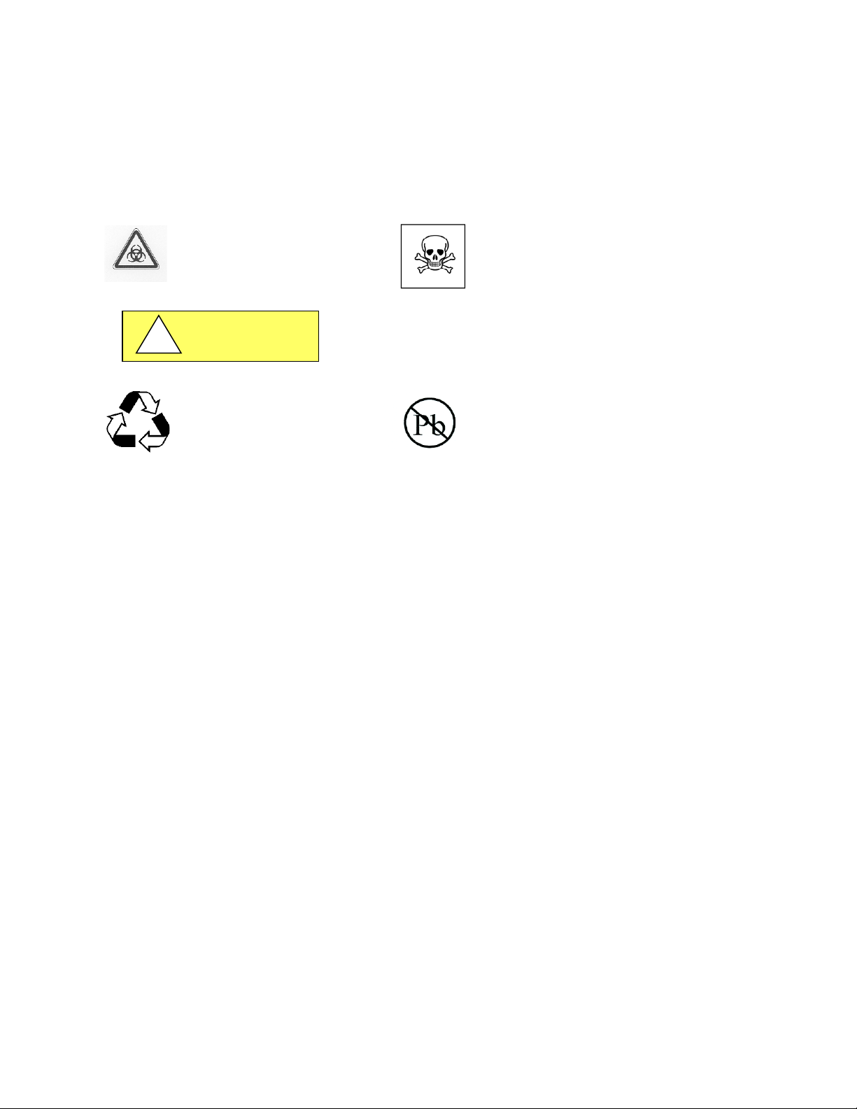
BIOHAZARD
RECYCLE
LEAD FREE
Chemical Hazard
CAUTION
!
Page 32

OM0089 Page 32 of 39
April/2021
11.0 Polypropylene Care and Use
NuAire products manufactured from Polypropylene materials require special consideration for the care and use to assure
maximum customer satisfaction. Polypropylene materials have many favorable characteristics, such as being resistant to
many chemicals, rigid, durable, and available in many thicknesses. NuAire fabricates the Polypropylene materials in many
different ways to produce a variety of products for the laboratory. Understanding about the care and use of the
Polypropylene material is important.
11.1 Cleaning
Regular cleaning can be done with gentle household or neutral cleaner. Don’t use sharp and/or scouring cleaning agents
as they could easily damage the surface. This also includes all liquid cleaning agents which contain abrasive whiting
(powdered chalk) or similar ingredients. Only use cleaning cloths, wipes or natural or synthetic sponges. A soft brush can
be used for crevices.
If an external surface static charge develops, spraying an anti-static solution on the affected area will eliminate the
problem.
NOTE: NuAire does not offer any product warranty with respect to cleaning material compatibility. USE AT YOUR OWN
RISK! The information provided above is from raw material suppliers and known general source documents for use to
develop application cleaning SOP’s.
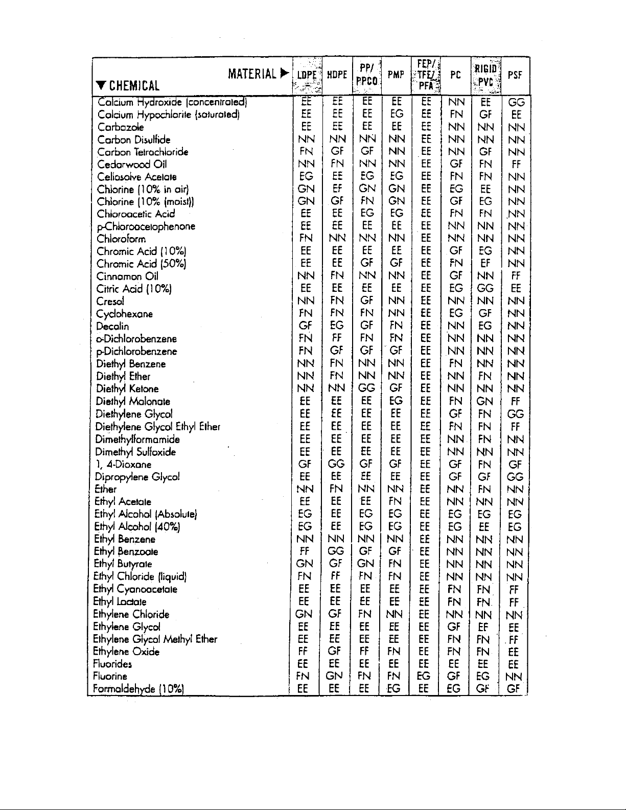
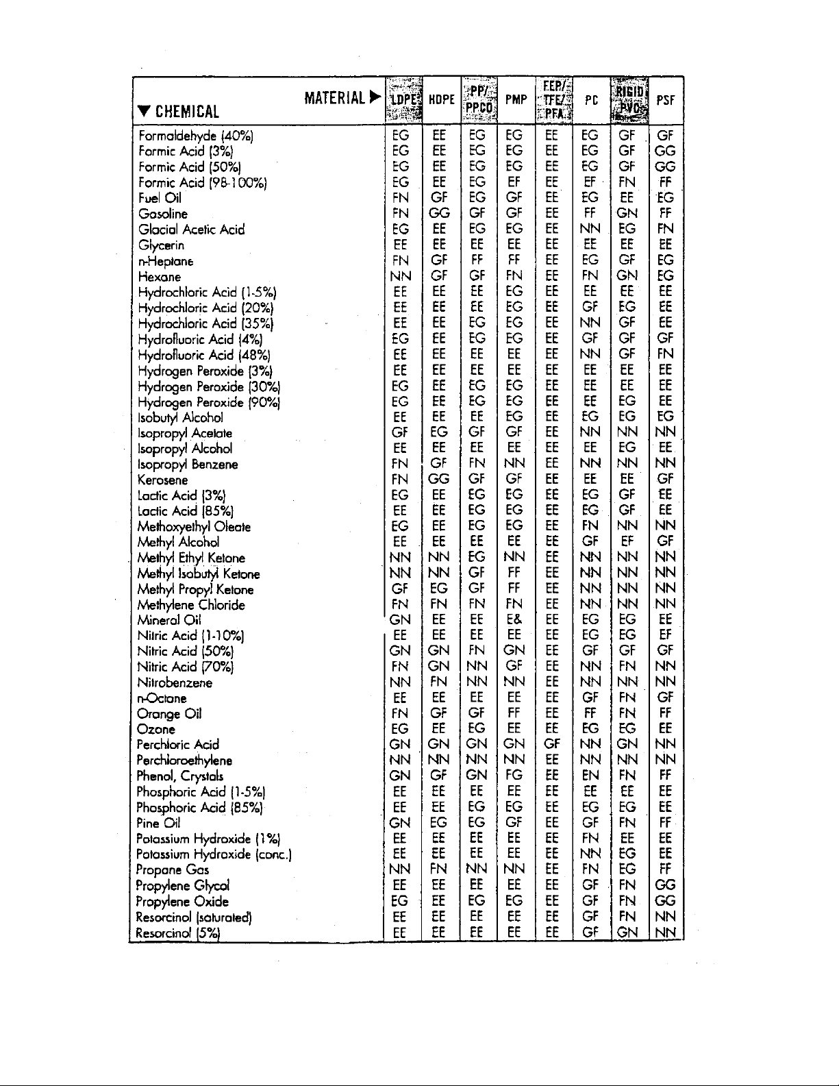
11.2 Material Compatibility
High concentrations of some acids may cause staining if in the constant contact with Polypropylene. Once it has
penetrated the surface of the material, only option would be to replace the surface, if at all possible.
See chemical resistance guide on following page for Polypropylene and other various types of plastics.
Page 33

OM0089 Page 33 of 39
April/2021
Page 34
OM0089 Page 34 of 39
April/2021
Page 35
OM0089 Page 35 of 39
April/2021
Page 36

OM0089 Page 36 of 39
April/2021
12.0 REPLACEMENT PARTS LIST
The following is a list of replacement parts. For replacement of electrical parts, refer to the electrical schematic. Please
consult NuAire, Inc. for parts not listed. To order, specify: model no., serial no. and part no.
Replacement Parts List
Model No.
HEPA Filter
HEPEX Plenum
Diffuser
Window
NU-156-424
24 x 36 x 6
A-980944-01
B-155-2129-01
B-151-1826-01
B-156-2099-01
NU-156-430
30 x 36 x 6
A-980944-04
B-155-2129-02
B-151-1826-05
B-156-2099-01
NU-156-524
24 x 48 x 6
A-980944-02
B-155-2129-03
B-151-1826-02
B-156-2099-02
NU-156-530
30 x 48 x 6
A-980944-05
B-155-2129-04
B-151-1826-06
B-156-2099-02
NU-156-624
24 x 60 x 6
A-980944-03
B-155-2129-05
B-151-1826-03
B-156-2099-03
NU-156-630
30 x 60 X 6
A-980944-06
B-155-2129-06
B-151-1826-07
B-156-2099-03
NU-156-824
24 x 84 x 6
A-156-2709-01
B-155-2129-07
B-151-1826-04
B-156-2099-04
NU-156-830
30 x 84 x 6
A-156-2709-02
B-155-2129-08
B-151-1826-08
B-156-2099-04
*Standard HEPA filter initial resistance is rated at 0.5” w.g. (12mm w.g.) at 100 LFPM (.51 m/s) (separatorless)
ULPA filter initial resistance is rated at 0.65” w.g. (16mm w.g.) at 100 LFPM (.51 m/s).
Page 37
OM0089 Page 37 of 39
April/2021
Page 38
OM0089 Page 38 of 39
April/2021
Page 39
OM0089 Page 39 of 39
April/2021
 Loading...