

Page 1

1 | P a g e R e v . 1 .1
I s s u e 3 0 - 11- 2018
The
SIL O
2
Oxygen Analyser
User Operation Manual
Rev. 1.1
30/11/2018
Page 2

2 | P a g e R e v . 1 .1
I s s u e 3 0 - 11- 2018
Page 3

3 | P a g e R e v . 1 .1
I s s u e 3 0 - 11- 2018
Contents
1. Introduction .................................................................................................................................................... 6
1.1 The purpose of this User and Operation Manual................................................................................... 6
2. Installation and Operation ............................................................................................................................... 7
2.1 Notes for a safe installation ................................................................................................................... 7
2.2 Installation ........................................................................................................................................... 10
2.2.1 Mounting the SIL O2 Analyser....................................................................................................... 10
2.3 Electrical and Interface Connections ................................................................................................... 11
2.3.1 Sensor Input and Customer Interface Wiring.................................................................................. 11
2.3.2 Operational Settings and Wiring Configuration ............................................................................. 12
2.3.3 Typical Relay Configuration........................................................................................................... 13
2.3.4 Sensor Process Connection options ................................................................................................ 15
2.4 Operation ............................................................................................................................................. 16
2.4.1 Calibration Procedures .................................................................................................................... 16
2.4.2 Setting the Zero point. .................................................................................................................... 17
2.4.3 SPAN Calibration ........................................................................................................................... 18
.......................................................................................................................................................................... 18
3. Operational safety and maintenance instructions.......................................................................................... 19
3.1 Fault conditions ................................................................................................................................... 19
3.2 Wire break ........................................................................................................................................... 19
3.3 System faults ....................................................................................................................................... 19
3.4 Troubleshooting .................................................................................................................................. 20
Possible Faults and their solutions ........................................................................................................................ 20
3.4.1 Possible Sensor Faults .................................................................................................................... 21
3.5 General Maintenance .......................................................................................................................... 22
4. Specifications................................................................................................................................................ 23
5. Appendices ................................................................................................................................................... 26
5.1 SIL O2 Analyser and Sensor Connection Diagrams ........................................................................... 27
5.2 SIL O2 Analyser CE and ATEX Certificates ...................................................................................... 28
5.3 Sensor CE and ATEX Certificates ...................................................................................................... 29
Page 4

4 | P a g e R e v . 1 .1
I s s u e 3 0 - 11- 2018
Revision History
Revision No.
Change Description
Date
0
First Issue
19-10-2018
1
Note added for Non-ATEX Sensor usage
22-10-2018
1.1
Reference to 15% O2 in trouble shooting section removed.
30-11-2018
Calibration Span instruction amended and note added
Page 5

5 | P a g e R e v . 1 .1
I s s u e 3 0 - 11- 2018
Page 6

6 | P a g e R e v . 1 .1
I s s u e 3 0 - 11- 2018
1. Introduction
The Ntron SIL O2 Analyser is a ATEX approved SIL 2 rated Oxygen measuring instrument. It contains three
programmable alarm settings, industry standard Analogue Output(active source) and a non-programmable safety
trip relay. The range of operation is 0 to 25% Oxygen. The Reasolution is to 0.01%.
Together with one of the range of Ntron ATEX approved Oxygen Sensors, it forms a SIL2 rated measurement
unit which can operate on its own or as part of a larger installation.
Note. Non-Atex (Ex) Sensors variants of the models listed in the manual may also be used with the SIL O2
Analyser as long as they are installed in a Non-ATEX (Ex) or ‚Safe‘ area or zone.
The Alarm settings are typically factory set according to the end user’s requirements. Interface software and
hardware is available for the user to perform such functions themselves. Contact Ntron for further details.
1.1 The purpose of this User and Operation Manual
This Manual is limited to providing the user with necessary details on installation, interface wiring, operation
and maintenance of the SIL O2 Analyser and Oxygen Sensor, to ensure safe and reliable operation of this
Analyser and Sensor unit.
Note: This manual does not cover the design or application of a safety Instrumented System (SIS) into
which the SIL O2 Analyser unit may be incorporated. Further details of this can be obtained in the Ntron
SILO2 Technical and Safety Manual.
Increase (UP) and
Decrease (Down)
Pushbuttons. Pressing
simultaneously enables
entry into the
calibration mode.
Power, Error/Fault and
Alarm Level indicators
RS232
Communications
connection
The main user interface features
4-Digit LCD
Display/Readout
Page 7
7 | P a g e R e v . 1 .1
I s s u e 3 0 - 11- 2018
2. Installation and Operation
Note: For system application information, consult the SIL O2 Analyzer
Technical User Manual
2.1 Notes for a safe installation
Please do not short-circuit the + and -ve sensor cables while connecting to the SIL O2 Analyzer. This
could damage the sensor.
This system can also be used in a non-Ex area application. In all applications, the SIL O2 Analyzer Din
rail module is always located in the non-Ex area!
Assignment of the mounting rail housing terminals with intrinsically safe circuits and non-intrinsically
safe circuits is indicated on the nameplate and is clearly indicated. In addition, the 4-pin terminals of
intrinsically safe circuits follow the standard color protocol for intrinsically safe terminal connections and
are coloured Blue. Connections for intrinsically safe external circuits are arranged in such a way that, in
accordance with EN 60079-11, the exposed parts are at least 50 mm from the exposed connections and
parts of the non-intrinsically safe circuits.
For safe operation, a protective ground/earth connection to terminal 13 or 15 should be made.
Assembly / disassembly, installation, operation and maintenance may only be performed by qualified
personnel in accordance with regulatory requirements and the SIL O2 Oxygen Analysis Manual.
During installation, the technical data and the electrical values of the connected circuits must be
respected.
Electrical supply. The SILO2 Analyser operates with an Extra low Voltage (ELV) supply. (See
specification section in this manual)No special precautions are necessary but the ELV supply to the SIL
O2, if generated from a Mains power source, that mains power source and associated wiring must be in
accordance with IEC/EN standards and is the responsibilty of the user to provide and to ensure correct
and safe installation of such.
When the SIL O2 analyzer is integrated into another system, also refer to the system manual for
additional operational information.
The Ntron SILO2 Analyser is designed for use with a range of Ntron ATEX certified Oxygen Sensors to
form a measurement system.These Sensor options are detailed in the Specification section of this manual.
If the SIL O2 Analyser has been supplied with a Sensor, the two units will have been calibrated at the
Ntron factory prior to delivery. Otherwise, if a Sensor is supplied separately from the SIL O2 Analyser, a
calibration will be required prior to putting the system into operational service.
Page 8

8 | P a g e R e v . 1 .1
I s s u e 3 0 - 11- 2018
The Ntron Sensors suitable for use with the SIL O2 analyser are listed in the Installationn section which
follows.
Page 9

9 | P a g e R e v . 1 .1
I s s u e 3 0 - 11- 2018
The SIL O2 oxygen analyzer is an associated explosion-proof [Ex ia] IIC or [Ex ib] IIC electrical device
and should always be used outside potentially explosive areas (in a safe area). Only electrical circuits,
certified as intrinsically safe, can be connected to other intrinsically safe circuits in the Ex zone.
Before operation, the intrinsic safety must be verified for the SIL O2 oxygen analyzer circuit connected
to the circuit of other equipment, including the interconnecting cabling.
The data contained in the EC test certificate and the regulations of EN 60079-14: 2011-10 must be
observed.
The Sensors are ATEX rated devices and have certain conditions of use assigned.
Note. Non-Atex (Ex) Sensors variants of the models listed in the manual may also be used with the
SIL O2 Analyser as long as they are installed in a Non-ATEX (Ex) or ‚Safe‘ area or zone.
For Acetal-bodies Sensors, the following instructions apply;
The Sensor should be installed in such a way that it is not subject to impact by other objects and should
not be located close to additional heat sources. Note the ambient temperature range as it appears on the
Sensor labelling.
Care must be taken when installing equipment with plastic enclosures or plastic parts of enclosures to
ensure that the equipment is protected from any situations that could cause a build up of static charge. The
equipment must not be installed into locations in which it could come into contact with, through normal
or abnormal circumstances, fast moving dust laden air/gas or non-conductive fluids. The equipment must
be cleaned only with a damp cloth.
Page 10
10 | P a g e R e v . 1 .1
I s s u e 3 0 - 11- 2018
2.2 Installation
The installation must be in accordance with the local electrical codes and taking into account the details
in the Specification section of this manual.
The SIL O2 analyzer is designed for DIN rail mounting and can be supplied mounted in an additional
enclosure or provided without an additional enclosure for customer mounting in a system enclosure or
control panel.
The Sensor option chosen will determine the process connection/installation for that Sensor type. The
Sensor types and related process connections are given below.
Sensor Type: Process Connection:
Model OC-25 Ntron Sensor base, Flow Through or Tri-Clamp
Model OC-26 KF40 Flange
Model OC-200’Oxyprobe‘ series Bushing insert or Extract* Probe Holder
The Sensor is typically supplied with a correcponding connection cable of either standard length or to a
customer specified length.
*The Ntron OxyExtract Manual or Automatic probe insertion mechanism.
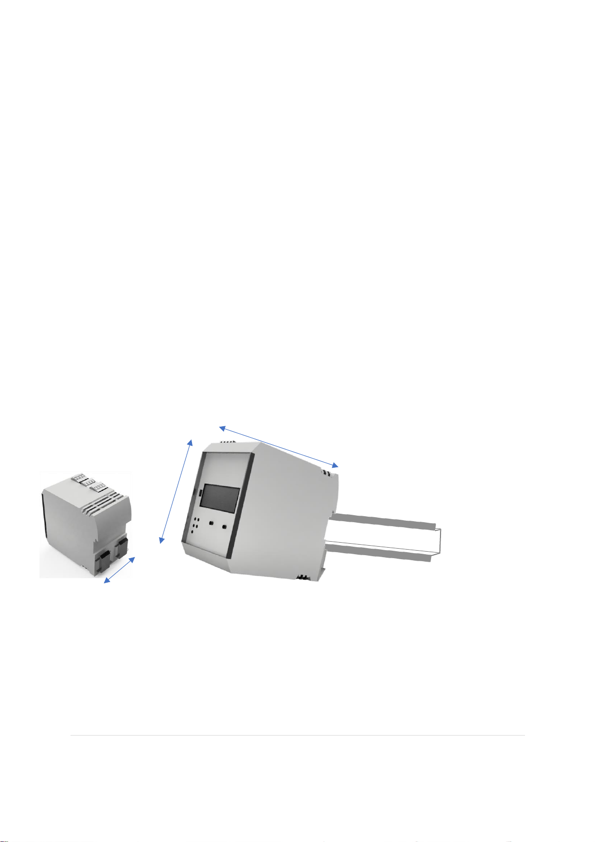
2.2.1 Mounting the SIL O2 Analyser
Mount the SIL O2 Analyser onto 35mm DIN rail as shown. Any Trunking/wireways above and below
the Analyer when in situ, must be positioned so that there is a minimum of 30mm clearance between
such trunking and the Analyser connection terminals.
115mm
100mm
67mm
Page 11
11 | P a g e R e v . 1 .1
I s s u e 3 0 - 11- 2018
2.3 Electrical and Interface Connections
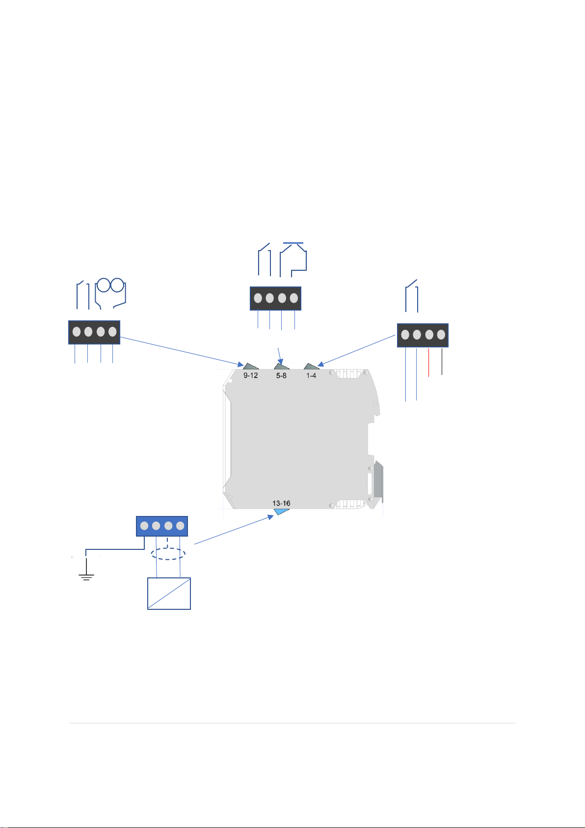
2.3.1 Sensor Input and Customer Interface Wiring
The Ntron ATEX Sensor selected for use with the SIL O2 Analyser as listed in the Installation section
previously, has intrinisically safe parameter values which match the Isolation Barrier output which is built into
the SIL O2 Analyser. The Sensor connects to the Blue terminals as shown below.
The dark Grey terminals are for safe (Non-Ex area) customer interface connections. See the configuration
section on the following page.
13 14 15 16
+ve -ve
Customer Clean
Earth
O2 Sensor
1 2 3 4
+ - 24 VDC
Relay 1
To customer Circuit
5 6 7 8
Relay 2 Transistor(DO)
To customer Circuit
9 10 11 12
Relay 3 4-20mA (AO)
To customer Circuits
Page 12
12 | P a g e R e v . 1 .1
I s s u e 3 0 - 11- 2018
2.3.2 Operational Settings and Wiring Configuration
The SIL O2 Analyser has two presettable alarm levels and associated Relays, referred to as RL1 and RL2. It
also has a third presettable alarm level with an associate Transistor Digital Output (DO) The programmed
setting of these outputs can vary depending on application. The Inspection and Calibration certificate supplied
with each SIL O2 Analyser and Sensor unit will detail these settings. See the Ntron SIL O2 Technical and
Safety manual for further details.
The SIL O2 Analyser has a main trip Relay referred to as RL3. This is not programmable and is normally
open(contacts)/de-energised when the Analyser is not under power. The Relay energises and its associate
contacts close when power is applied and the Analyser and Sensor are healthy and ready to operate.
The Analogue output is an industry standard 4-20mA active source output. The connected circuit should be of
maximum resistance 420 ohm.
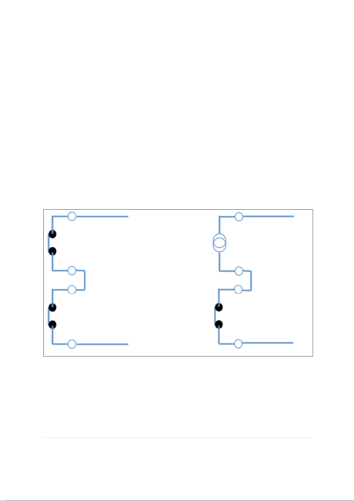
To meet the SIL 2 operational requirements as an Analyser and Sensor unit, the main trip Relay is required to be
connected in series with other elements within the Analyser as shown in the diagrams below. For any other
configurations, See the Ntron SIL O2 Technical and Safety manual for further details.
*Special case for use of the 4-20 mA analogue output within a safety system
When using the 4-20 mA analogue output from the SILO2 Oxygen Analyser within the safety
system, this signal would typically be required to be processed by a safety PLC which would then
activate the Final Trip Element. See the Ntron SIL O2 Technical and Safety manual for further
details.
Relay 3 Main Trip
Relay 1 or 2
Relay 3 Main Trip
Analogue Output
1/5
2/6
9
10 9 10
11
12
Page 13
13 | P a g e R e v . 1 .1
I s s u e 3 0 - 11- 2018
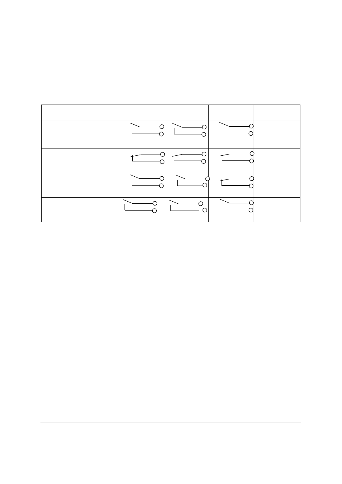
2.3.3 Typical Relay Configuration
Power to the Analyser
Relay
Contact 1
Relay Contact
2
Relay Contact
3
Comments
Power Off
(All relay contacts in Fail
Open condition)
Relays
De-energised
Power on and system
good/healthy
**
** All Relays
Energised
Power on and O2 alarm
level(s) reached
* *
Relays 1 & 2
De-energised
Power on and System fault
**
** All Relays
De-energised
These relays are programmed to respond to the measured Oxygen level setpoints (Alarms), rising or falling in
the range 0-25% Oxygen. These are pre-set to the customer’s requirements.
They operate in ‘Fail Safe’ mode which means that they are energized (under current), presenting a closed
contact to the customer/user when the SIL O2 module is under power and the status is healthy/good.
When at a level setpoint (Alarm) or when the SIL O2 module is not-powered, the relays are de-energised (not
under current), presenting an open contact to the customer/user. This is also known as ‘Fail Open’ (FO)
condition.
Transisitor (DO)
This is an NPN device that can switch 24VDC and can be configured to be normally open or normally closed.
Analogue 4-20mA
This is an active output and requires connection to a passive external circuit suitable for proper operation.
It is set to the range 0-25% Oxygen / 4-20mA (0% Oxygen = 4mA, 25% Oxygen = 20mA.)
This range can not be adjusted.
If the 4-20 mA output is not used, the SIL O2 terminals T11 and T12 must be wired by the user. This output is
internally connected in series with the SIL O2 Analyzer digital display, which will not work if the
aforementioned terminals are in open circuit!
Page 14

14 | P a g e R e v . 1 .1
I s s u e 3 0 - 11- 2018
Page 15

15 | P a g e R e v . 1 .1
I s s u e 3 0 - 11- 2018
2.3.4 Sensor Process Connection options
The Sensors are suitable for mounting directly onto process
Lines via a selection of process fittings. The electrical signal connectors
are rated to IP67.
Tri-Clamp Sensor Base
Flow Through Sensor Base
OC-25 Sensor
OC-26 Sensor KF40 Process fitting
KF40 Process fitting onto pipeline
OC-200 Sensor with Screwed Bush Process
fitting
Page 16

16 | P a g e R e v . 1 .1
I s s u e 3 0 - 11- 2018
2.4 Operation
Before turning on the SIL O2 analyzer for the first time or after disconnecting the sensor for maintenance /
replacement, make sure that a working sensor is connected. Otherwise, the SIL O2 analyzer will go into failure
mode, with the red error indicator on and the RL3 relay disabled. As the fault circuit performs a cyclic check
every 30 seconds or so. When the sensor is connected, resetting the red indicator and relay 3 occurs
automatically, but it is advisable to power off the system to allow the sensor to be disconnected / reconnected
under normal circumstances, if possible.
Turn on/apply power to the SIL O2 Analyser.
When operating under normal process/system conditions, the SIL O2 Analyser will give a digital readout of the
measured Oxygen level (from the Sensor in the process).
This measurement is converted into a 4-20mA output signal proportional to the Oxygen being measured.
If an Alarm level even occurs, the relevant programmed output device will operate (Relay or Transistor) and the
ineterface circuit to the user equipment will be interrupted. For further alarm or fault events and their conditions,
please see the troubleshooting section at the end of this Manual.
2.4.1 Calibration Procedures
The SIL O2 Analyser and Sensor unit requires periodic calibrations performing, the timing between such
calibrations being determined by the application and process requirements.
Typically, a periodic calibration check would reveal if any calibration adjustment is necessary. The SPAN
calibration point of 20.9% O2 (Air) is the important setting and typically, if calibration adjustment is required,
this is the value that would be adjusted. This adjustment can be made ussing ambient air as the calibration
standard or, for greater accuracy, certified cylinder gas at 20.9% O2.
It is possible to also adjust the Zero point of the SIL O2 Analyser. Typically this would only be required when
fitting a new/replacement Sensor. A Complete calibration procedure is given below.
Note: Calibration Adjustment procedure.
The displayed number change starts with the digit to the far right of the decimal point. Press and hold the
Up or Down buttons to change the reading. This gives an accelerated adjustment. More accurate
adjustment is achieved by pressing the Up or Down button at one press (press release, release of press,
etc.). When the display reads 20.9%, the calibration of the range is complete
19.05
19.05
1, 2, 3….
6
6
1-
Page 17

17 | P a g e R e v . 1 .1
I s s u e 3 0 - 11- 2018
2.4.2 Setting the Zero point.
This must be done each time a new sensor is installed before a span calibration is performed.
Subsequently, a zeroing can be performed periodically as needed.
A zeroing operation requires the application of a zero oxygen gas to the sensor, typically nitrogen (minimum
quality <100 ppm). Note: Accessing the Zero function when the sensor is in ambient air (20.9% O2) will result
in an error / fault condition.
Depending on the type of sensor installed, zero gas must be applied through a process fitting or calibration
adapter, and be sure to leave a free exhaust at a suitable location so that the sensor does not become pressurized.
The sensors to be used with the SIL O2 unit will generally give a small output at zero oxygen levels. The zero
adjustment function allows the user to adjust this small signal so that the SIL 2 analyzer displays 0.0 when no
oxygen is present in the measured gas.
• ZERO mode is activated after pressing the UP and DOWN button simultaneously for more than one
second. As an acknowledgment of receipt, the A3 LED flashes. An adjustment of the indicated value is
made by pressing the UP or DOWN buttons individually as required.
• The change starts with the digit to the right of the decimal point. (00.0) Press and hold the Up or Down
buttons to change the displayed reading. This allows an accelerated adjustment. Accurate adjustment is
achieved by pressing the Up or Down button at one press (press release, release of press, etc.). When
the display reads 0.0% O2, the setting is complete. By simultaneously pressing the two buttons or a
delay of 20 seconds, the ZERO operating mode ends.
0.00
Page 18

18 | P a g e R e v . 1 .1
I s s u e 3 0 - 11- 2018
2.4.3 SPAN Calibration
This can be done periodically or as needed in accordance with the requirements of the calibration protocol.
Calibration can be performed by applying either clean ambient air or a 20.9% certified oxygen rate to the sensor.
Note:
• The SIL 2 analyzer should only be calibrated at approximately 20.9% oxygen.
• If an ambient air calibration is performed, it is recommended to confirm the oxygen level with a
certified portable oxygen analyzer prior to calibration.
• If a zero setting is made first, then after the end of the zero operation mode, the Span mode is
automatically activated after a delay of 20 seconds.
• If A Span only calibration is required, then just press the UP or DOWN buttons individually to
increase or decrease the displayed value of oxygen to read 20.9. Note: Ensure the Sensor is in
20.9% oxygen when you do this!
• Calibration complete.
20.90
Page 19

19 | P a g e R e v . 1 .1
I s s u e 3 0 - 11- 2018
3. Operational safety and maintenance instructions.
If it is assumed that safe operation is no longer possible, the device must be taken out of service and protected
against accidental use. The reasons can be:
visible damage to the device
failure of the electrical function
long shelf life at temperatures above 85 ° C
Transport damage
Before the device can be put back into service, a professional routine check must be carried out in accordance
with DIN EN 61010, part. 1. This examination must be carried out by the manufacturer. Repair work on Ex devices
may only be carried out in accordance with § 9 of Ex. (Elex V).
3.1 Fault conditions
The SIL O2 Analyzer failure operation is not locked out by a fault. When a fault condition is repaired, the trip
relay RL3 and the red fault indicator will return to their "healthy" or "operational" state after a few seconds
following an automatic internal cyclic check.
3.2 Wire break
When manually disconnecting the sensor (for example for maintenance) or following a break in the sensor
connection cable, the SIL O2 Analyzer RL3 fault relay switches off and interrupts the safety circuit.
The red fault indicator will illuminate on the SIL O2 analyzer and the 4-20 mA analog output will reach a constant
high value of 22.0 mA. At the same time, the setpoint relays RL1 and RL2 will be deactivated.
When the sensor is reconnected or the cable fault is corrected, the RL3 relay automatically resets after about 30
seconds and the red LED goes out. At the same time, RL1 and RL2 are reset according to their setpoints and the
measured gas level. See also note on page 13 of this manual for reset requirements under specific conditions.
3.3 System faults
A number of internal faults in the SIL O2 analyzer generate a fault output and interrupt the safety circuit. In some
cases, cycling the power supply of the SIL O2 analyzer may be sufficient to remedy the problem. Otherwise,
please contact Ntron for assistance.
Page 20

20 | P a g e R e v . 1 .1
I s s u e 3 0 - 11- 2018
3.4 Troubleshooting
Possible Faults and their solutions
The following possible conditions are applicable to a system (Sil Analyser and Sensor) already installed
and commissioned. Some conditions below may also be applied to new systems not yet commissioned.
• Action: Performing a Zero calibration when the Oxygen Sensor is in ambient air.
Problem: An incorrect Zero level input to the Analyser will result in an overrange fault. This can
occur if a Zero calibration is performed when the Sensor is in ambient air. If this occurs, the Red fault
LED will illuminate and the Analyser display and Analogue output will read an over-range value. The
Alarm level LED’s may also illuminate. This may also occur if a genuine overrange event takes place,
with gas containing more than 25% O2 being applied. (25%O2 displayed)
Solution: re-calibrate with Nitrogen gas (Zero) and then re-calibrate at the Span point of 20.9%.
• Action: Powering on the Analyser with no sensor connected or a wire break to the sensor.
Problem: If the sensor is disconnected, this would ordinarily cause relays R1, R2 and R3 to de-
energise. Analyser display and Analogue output will read a fault value. (28% O2 displayed and 22mA
output)
Solution: Check Sensor wiring and connect the sensor to the Analyser. After approximately 30
seconds, the Analyser will reset and the Red LED should extinguish.
• Action: Unable to perform a Span calibration.
Problem: The Analyser cannot be adjusted to display 20.9% O2 during Span calibration.
Solution: The Sensor may be approaching end of life or has been damaged and cannot generate
sufficient output. Replace the sensor
Alarm level LED’s may or may not be illuminated depending on configuration.
• Action: Alarm Level LED’s (Yellow) illuminated.
Problem: Alarm level LED’s illuminated.
Solution: Genuine Oxygen level alarm event.
Incorrect sample gas levels being applied to the Sensor or incorrect alarm level settings are configured
within the Analyser. If this is not expected then check sample gas with independent instrument
gas/and/or re-configure Analyser Alarm setpoints. This will require interface with PC based software.
Page 21

21 | P a g e R e v . 1 .1
I s s u e 3 0 - 11- 2018
• Action: Red Fault LED illuminated when none of the above conditions are present.
Problem: Analyser in fault condition. Analyser display and Analogue output will read a fault value.
(28% O2 displayed and 22mA)
Solution: Internal Analyser electronics or programming fault. Try Power On/Off cycle to reset.
If fault does not clear then seek further assistance.
Problem: No Analyser display (Blank)
Solution: Analogue output circuit is broken or interrupted. Investigate and repair.
3.4.1 Possible Sensor Faults
Applicable to all sensor types (OC-25, OC-26, OC-200)
Problem:. SIL O2 Analyser will not calibrate (Cannot be set to 20.9%)
Solution: Sensor is at end of life. Sensor has been wetted or contaminated. The Sensor output signal can be
checked at the SIL O2 Analyser terminals 14 and 16. See specification section for details of a healthy
output signal.
Problem:. SIL O2 Analyser reads Zero (0.00)
Solution: Actual low Oxygen measurement. Sensor wires have been shorted together, damaging the Sensor.
Verify the Oxygen level by other means. Check the Sensor output signal. Replace Sensor as necessary.
Page 22

22 | P a g e R e v . 1 .1
I s s u e 3 0 - 11- 2018
3.5 General Maintenance
Establish a periodic checking and maintenance routine in line with the requirements for Safety Instrumented
Systems. See the Ntron SIL O2 Analyser Technical and Safety manual for further details.
The SIL O2 Analyser requires little physical maintenance. The user Enclosure into which it is housed
should provide protection against a build up of dust or other contaminants on the surface of the SIL O2
Analyser housing. If such contaminants are seen during regular inspection, such can be removed by gentle
suction device or by wiping with a damp but not wet, cloth. The ingress of such contaminants should be
investigated.
Ensure all wiring to the SIL O2 Analyser is secure and in good condition, paying particular attention to the
security of the connection terminals if the user enclosure is subject to vibrations.
There are no user serviceable parts within the SIL O2 Analyser. If any malfunction is detected, mechanical
or electrical, the SIL O2 Analyser should be immediately removed from service following the correct
protocols.
The Sensor used has a finite life span. The Performance of the Sensor is verified by calibration check and
this should be performed according to the protocols required by the safety system. Replacement of the
Sensor is necessary when it does not meet the required performance levels.
During operation life, the Sensor should be kept clean of contaminants. It can be wiped with a soft damp
cloth. Observe the restrictions regarding potential static charges as detailed on the Sensor Installation
Instruction Documents found in the appendix to this manual.
When removing Sensors from their process installation for replacement or other service requirements,
observe the following points.
• Ensure any and all system shut down protocols are followed as applicable.
• Do not disconnect the Sensor from the connecting cables whilst the system is operating or is
‘Live’.
• Ensure the process being measured is shut down or the Sensor connection is isolated by any
intermediate valve mechanism if fitted.
• Always remove the Sensor connector before unscrewing the OC-25/OC-200 Sensors or
unclamping the OC-26 Sensors from their process fittings
• Block off the exposed process connection if required during the period the Sensor is disconnected.
• Protect the disconnected Sensor cable from damage during the period the Sensor is disconnected.
Page 23

23 | P a g e R e v . 1 .1
I s s u e 3 0 - 11- 2018
4. Specifications
SIL O2 Analyser
Specifications-Electrical
Supply Voltage
24VDC +/- 10%
Supply Power
1.5 Watt
Analogue Output
4-20mA active source. 22mA Max output . Load 390 Ohm@22mA, Max
420 Ohm@20mA constant current.
Communications
RS232/Com 9600bps
Relay Contact outputs
RL1/RL2/RL3
Um 125VAC/110VDC (Typically 30VDC)@ 1Amp. Min Current 10uA
DC. Min. Voltage 10mVDC. Type According to IEC 947-5-1 resp. EN
60947)
Transistor Output (Do)
Switching parameters: <28V @<50mA
Intrinsically Safe
Connection
voltage Uo DC 6 V
current intensity Io 0,2 mA
power Po 0,3 mW
max. outer inductivity Lo 1000 mH
max. outer capacity Co 10 μF
Specifications-Mechanical
Terminal /Wire Size
Pluggable/Quick Releas terminals, capacity 2.5mm
2.
Mounting
35mm Din rail
Housing Material
PBT
Protection Class
IP20
Combustibility Class
VO according to UL
Weight
300g
Enviromental
Temperature: -20 to +60°C, 10-95% Humidity, no condensation.
Dimensions
67 mm x 114.5 mm x 99 mm
Indications
4 Digit LCD Display, Green OK led, Red Fault LED, Amber Alarm LED.
Page 24

24 | P a g e R e v . 1 .1
I s s u e 3 0 - 11- 2018
Certification/Standards
CE, ATEX 2014/34/EU/ EN 60079-0:2012 + A11:2013, EN 60079-
11: 2012, EN 60079-26: 2015 0158 II (1) G II (1) D ; [Ex ia
Ga] IIC; [Ex ia Da] IIIC
Functional safety: SIL2 according to IEC 61508/61511
EMC 2014/30/EU
EN 61326-3-2:2008; EN 61000-6-3: 2007 + A1: 2011
EN 61000-4-2:2009; EN 61000-4-3: 2006 + A1: 2008 + A2: 2010
EN 61000-4-4:2012
2006 + A1: 2008 + A2: 2010
EN 61000-4-5:2014
EN 61000-4-6:2014
Oxygen Sensor
Specifications-Electrical
Models
OC-25, OC-26, OC-200 series
Range
0-25% Oxygen
Signal Output
300-375mV in Air OC25, OC-26. 135-160mV in Air OC-200
Technology/Lifespan
Electrochemical Solid State Long Life / 3-5+ Years application
dependant. Storage Life 1 Year.
Connections
Circular Pluggable IP67 Connector with cable to specified length.
Intrinsically Safe Sensor
Input Connection
Parameters.
voltage Uo DC 12 V
current intensity Io 120 mA
power Po 0.55 W
max. outer inductivity Lo 0 mH
max. outer capacity Co 1.2 μF
Specifications-Mechanical
Dimensions OC-25
100mm High x 50mm Diameter
Dimensions OC-26
75mm High x 55 Diameter (KF40)
Dimensions OC-200
Variable length to order, typically 200mm long x 12mm Diameter probe.
Max. Diameter is 30mm.
Page 25

25 | P a g e R e v . 1 .1
I s s u e 3 0 - 11- 2018
Protection Class
IP67 When inserted into process fitting with Connector fitted.
Process Connection
OC-25 =Ntron Sensor base; OC-26 = KF40 Flange, OC-200 = Probe
Holder mechanism or Bushing
Weight
OC-25= 250g; OC-26=150g, OC-200=180g
Environmental
Temperature: -20 to +45-50°C, 10-95% Humidity, no condensation.
Certification/Standards
CE, ATEX 2014/34/EU/ 1180 II 1 GD
EN60079-0:2012 + A11:2013
EN60079-11:2012
ATEX II 1 GD; Ex ia IIC T6 Ga(-20°C≤Ta≤+55°C)
Ex ia IIIC T90°C Da( -20°C≤Ta≤+55°C)
IECEx BAS 09.0148X
Page 26

26 | P a g e R e v . 1 .1
I s s u e 3 0 - 11- 2018
5. Appendices
• SIL O2 Analyser and Sensor Connection Diagrams
• SIL O2 Analyser CE and ATEX Certificates
• Sensor CE and ATEX Certificates
Page 27

27 | P a g e R e v . 1 .1
I s s u e 3 0 - 11- 2018
5.1 SIL O2 Analyser and Sensor Connection Diagrams
• E364 SIL O2 with OC-25 Sensor
• E511 SIL O2 with OC-26 Sensor
• E395 SIL O2 with OC-200 ‘Oxyprobe’
Page 28

Gas Measurement
Page 29

Gas Measurement
Page 30

Gas Measurement
Page 31

Gas Measurement
Page 32

Gas Measurement
Page 33

28 | P a g e R e v . 1 .1
I s s u e 3 0 - 11- 2018
5.2 SIL O2 Analyser CE and ATEX Certificates
• CE Certificate CETX003
• ATEX Certificate Dekra BVS 13 ATEX E 010
Page 34

Rev. 1.5
25/02/2019 Page 1 of 2
CETX003
En: We declare, under our full responsibility, that we believe the products identified in this declaration,
and to which this declaration relates are in conformity with the requirements of Council Directives:
D: Wir erklären unter unserer vollen Verantwortung, dass wir glauben, dass die Produkte in dieser Erklärung identifiziert, auf die sich diese
Erklärung bezieht, in Übereinstimmung mit den Anforderungen der Richtlinien:
Fr: Nous déclarons, sous notre entière responsabilité, que nous croyons que les produits identifiés dans la présente Déclaration, et à
laquelle se réfère cette déclaration sont conformes aux exigences des directives du Conseil:
Es: Declaramos, bajo nuestra responsabilidad exclusiva, que creemos que los productos identificados en esta declaración, y al cual se
refiere esta declaración son conformes con los requisitos de las Directivas del Consejo:
It: Dichiariamo, sotto la nostra piena responsabilità, che crediamo i prodotti identificati in questa dichiarazione, e al quale questa
dichiarazione si riferisce sono conformi alle prescrizioni delle direttive del Consiglio:
This product meets the specifications according to the following European directives:
Dieses Produkt erfüllt die Spezifikationen nach den folgenden Europäischen Richtlinien:
Ce produit est conforme aux spécifications selon les directives Européennes suivantes:
Este producto cumple con las especificaciones de acuerdo a las siguientes directivas Europeas:
Questo prodotto soddisfa le specifiche in base alle seguenti direttive Europee:
Directive/ Richtlinie/ directive/ directiva/ direttiva 2014/34/EU- Equipment and protective systems intended
for use in potentially explosive atmospheres./Richtlinie 2014/34 / EU Geräte und Schutzsysteme zur bestimmungsgemäßen
Verwendung in explosionsgefährdeten Bereichen/ Directive 2014/34 / EU équipements et systèmes de protection destinés à être utilisés
dans des atmosphères explosibles./ Directiva 2014/34 / UE equipos y sistemas de protección destinados a ser utilizados en atmósferas
potencialmente explosivas./ apparecchiature e sistemi di protezione destinati all'uso in atmosfere potenzialmente esplosive.
Directive/ Richtlinie/ directive/ directiva/ direttiva 2014/30/EU–Electromagnetic
Compatibility/Elektromagnetische Verträglichkeit/Compatibilité électromagnétique/ Compatibilidad
Electromagnética/Compatibilità Elettromagnetica
Directive/ Richtlinie/ directive/ directiva/ direttiva 2011/65/EU and of Council of 8th June 2011 on the
restriction of the use of certain hazardous substances in electrical and electronic equipment (RoHS2)(*)
*OJ L 174, 1.7.2011, p.88 & P106 Annex IV 1b exemption./ und vom Rat vom 8. Juni 2011 zur Beschränkung der Verwendung
bestimmter gefährlicher Stoffe in Elektro- und Elektronikgeräten (RoHS2) (*)
ABl. L 174 vom 1.7.2011, S. 88 und P106 Anhang IV 1b Befreiung./ et du Conseil du 8 juin 2011 sur la limitation de l'utilisation de
certaines substances dangereuses dans les équipements électriques et électroniques (RoHS2) (*)
* JO L 174 du 1.7.2011, p.88 et P106 Annexe IV 1b./ y del Consejo de 8 de junio de 2011 sobre la restricción del uso de determinadas
sustancias peligrosas en equipos eléctricos y electrónicos (RoHS2) (*)
* DO L 174 de 1.7.2011, p.88 y P106 Anexo IV 1b exención./ e del Consiglio, dell'8 giugno 2011, sulla restrizione dell'uso di talune
sostanze pericolose nelle apparecchiature elettriche ed elettroniche (RoHS2) (*)
* GU L 174 dell'1.7.2011, pag.88 & P106 Allegato IV, punto 1b.
Description of Equipment/Beschreibung des Gerätes/Description de l'équipement/Descripción de
Equipo/Descrizione delle attrezzature:
SilO2 Oxygen Analyser.
SilO2 Sauerstoff Analyser.
SilO2 Analyseur d'oxygène.
SilO2 Analizador de Oxígeno.
SilO2 analizzatore di ossigeno.
EU Declaration of Conformity/ EG-Konformitätserklärung/ Déclaration de
conformité CE/ Declaración de conformidad CE/ Dichiarazione di conformità
CE.
Page 35

Rev. 1.5
25/02/2019 Page 2 of 2
CETX003
Standards and marking/ Standards und Kennzeichnung/ Normes et marquage/ Normas y marcado/ Norme e
marcatura:
ATEX:
EMC:
EN 60079-0: 2012 + A11: 2013
Explosive atmospheres - Part 0: Equipment - General requirements.
EN 60079-11:2012 Explosive atmospheres - Part 11: Equipment protection by intrinsic
safety “i”.
EN61326-3-2:2008 Electromagnetic compatibility – immunity requirements for safety
related systems and for equipment intended to perform safety related functions in
industrial applications with specified electromagnetic environment.
EN 61000-6-3: 2007 + A1: 2011, Emissions Light Industrial
EN61000-4-2:2009, Electrostatic Discharge
EN61000-4-3: 2006 + A1: 2008 + A2: 2010, Immunity Heavy Industrial
EN61000-4-4:2012, Burst Immunity
EN61000-4-5:2014, Surge Immunity
EN61000-4-6:2014, Conducted Immunity
II (1)G (Ex ia Ga) IIC
II (1)D (Ex ia Da) IIIC
Notified body:
Benannte Stelle:
Organisme notifié:
Organismo notificado:
Organismo notificato:
DEKRA Exam GmbH.
Dinnendahlstrasse 9
44809 Bochum
Germany.
BVS 13 ATEX E 010
The Authorised Signatory to this declaration, on behalf of the manufacturer, is identified below:
Der Prokurist dieser Erklärung im Namen des Herstellers, ist unten angegeben:
Le Signataire autorisé à cette déclaration, le nom du fabricant, est identifié ci-dessous:
El Signatario autorizado a esta declaración, en nombre del fabricante, se identifica a continuación:
Il Firmatario autorizzato a tale dichiarazione, per conto del produttore, viene identificata di seguito:
Name/ Nom/Nombre/Nome:
David Beirne
Title/Position; Titel / Position; Titre / Position; Título / Puesto; Titolo / Ruolo :
Managing Director/Geschäftsführer /Directeur Général/ Director Gerente/Amministratore Delegato
Address/Anschrift/ adresse/ dirección/indirizzo
Ntron Ltd, Mullaghboy Industrial Park, Navan, Co. Meath, Ireland.
Signature Date: 25/02/2019
Standards applied:
Normen:
Normes appliquées:
De normas vigentes:
Norme di riferimento:
Equipment marking:
Kennzeichnung der Anlagen:
Matériel de marquage:
Equipo de marcado
Contrassegno degli impianti:
Page 36

Page 37

Page 38

Page 39

Page 40

Page 41

Page 42

Page 43

Page 44

Page 45

Page 46

29 | P a g e R e v . 1 .1
I s s u e 3 0 - 11- 2018
5.3 Sensor CE and ATEX Certificates
• CE Certificate SUII01, SUII02
• ATEX Certificate BAS02ATEX1230X-11
Page 47

Document: SUII01 Rev. 15
Description of Equipment:
Beschreibung des Gerätes:
Description du matériel:
Descripción de la máquina:
OC-Type Oxygen Sensors For Use in Hazardous Areas.
Standards applied:
Normes appliquées:
Normas aplicadas:
EN60079-0:2012 + A11:2013
EN60079-11:2012
Marking:
Kennzeichnung:
Marquage:
Marcado:
II II 1 GD Ex ia IIC T6 Ga(-20°C≤Ta≤+55°C)
Ex ia IIIC T90°C Da( -20°C≤Ta≤+55°C)
Certificate No: BAS02ATEX1230X
(Other markings: IECEx BAS 09.0148X)
Notified Body:
Benannte Stelle:
Organisme notifié:
Organismo notificado:
SGS Baseefa
Rockhead Business Park
Staden Lane, Buxton, Derbyshire,
SK17 9RZ, UK.
Notified Body Number: 1180
The Authorised Signatory to this declaration, on behalf of the manufacturer, is identified below:
Name: David Beirne Title/Titel/ Titre/ título: Managing Director/Geschäftsführer/Directeur-Général/director Gerente
Address/Adresse/ dirección: Ntron Ltd Ph: 00353469071333
Mullaghboy Industrial Estate Fx: 00353469071331
Navan email: info@ntron.com
Co. Meath Web: www.ntron.com
Ireland, C15 XD61
Signature: Date: 12/02/2019
EU Declaration of Conformity
EG-Konformitätserklärung / Déclaration de conformité CE /
Declaración de conformidad CE:
We declare, under our sole responsibility, that we believe the products identified in this declaration, and to which
this declaration relates are in conformity with the requirements of the EU Council Directives as stated below;
Directive 2014/34/EU equipment and protective systems intended for use in potentially explosive atmospheres.
Directive 2011/65/EU and of Council of 8th June 2011 on the restriction of the use of certain hazardous substances
in electrical and electronic equipment (RoHS2)(*)
*OJ L 174, 1.7.2011, p.88 & P106 Annex IV 1b exemption.
Wir erklären in alleiniger Verantwortung, dass wir der Ansicht sind, dass die in dieser Erklärung genannten Produkte, auf die sich diese
Erklärung bezieht, den Anforderungen der unten aufgeführten Richtlinien des EU-Rats entsprechen; Richtlinie 2014/34 / EU Geräte und
Schutzsysteme zur bestimmungsgemäßen Verwendung in explosionsgefährdeten Bereichen.Richtlinie 2011/65 / EU und des Rates vom 8. Juni
2011 zur Beschränkung der Verwendung bestimmter gefährlicher Stoffe in Elektro- und Elektronikgeräten (RoHS2) (*)* ABl. L 174 vom
1.7.2011, S. 88 & S. 106 Anhang IV 1b Befreiung.
Nous déclarons, sous notre seule responsabilité, que nous croyons que les produits identifiés dans cette déclaration, et auxquels cette déclaration
se rapporte, sont conformes aux exigences des directives du Conseil de l'UE comme indiqué ci-dessous;Directive 2014/34 / EU équipements et
systèmes de protection destinés à être utilisés dans des atmosphères explosibles.Directive 2011/65 / UE et du Conseil du 8 juin 2011 relative à la
limitation de l'utilisation de certaines substances dangereuses dans les équipements électriques et électroniques (RoHS2) (*) * JO L 174 du
1.7.2011, p.88 et P106 Annexe IV 1b.
Declaramos, bajo nuestra exclusiva responsabilidad, que creemos que los productos identificados en esta declaración, y a los que se refiere esta
declaración, están en conformidad con los requisitos de las Directivas del Consejo de la UE como se establece a continuación; Directiva 2014/34
/ UE equipos y sistemas de protección destinados a ser utilizados en atmósferas potencialmente explosivas. Directiva 2011/65 / UE y del Consejo,
de 8 de junio de 2011, sobre la restricción del uso de determinadas sustancias peligrosas en aparatos eléctricos y electrónicos (RoHS2) (*) * DO
L 174 de 1.7.2011, p.88 y P106 Anexo IV 1b exención.
Page 48

Ntron Ltd, Mullaghboy Ind Est, Navan, Co. Meath, Ireland. Ph: ++353 46 9071333 Fx: ++353 46 9071331 Doc No: SUII01 Rev.15
ENGLISH SENSOR USE/INSTALLATION INSTRUCTIONS To ensure security of personnel, goods and plant it is important that the
national standards laid down for the installation of electrical equipment
are followed, that instructions on the nameplate are achieved, and that
the work is carried out by trained personnel. Furthermore, it is necessary
to use the oxygen sensor in accordance with the advice and data given in
this text.
Oxygen sensors for hazardous areas are especially designed to conform
to national and international standards governing risks of explosion and
certificates for each type are issued by an approved organisation or
notified body. Be careful ! A certification number followed with “X” or a
“U” requires specific conditions for use.
1. Care must be taken when installing equipment with plastic enclosures or
plastic parts of enclosures to ensure that the equipment is protected from
any situations that could cause a build up of static charge. The equipment
must not be installed into locations in which it could come into contact with,
through normal or abnormal circumstances, fast moving dust laden air/gas
or non-conductive fluids. The equipment must be cleaned only with a damp
cloth.
2. When installing equipment with Metal enclosures, earthing of the metal
enclosure must be ensured to avoid the potential of electrostatic discharge. STORAGE
The sensor should be stored in a cool dry place.
HANDLING WARNINGS
Do not expose open end of sensor housing to liquids, particulates,
grease, or oil.
Do not touch top of sensor within open end of sensor housing.
Do not allow vacuum grease to coat open end of sensor.
Do not expose sensor to sudden mechanical shocks.
INSTALLATION & CALIBRATION
Remove the sensor connector plug from the old sensor.
Remove the old sensor by uscrewing counterclock wise or by removing
from housing.
Remove and dispose of the old sealing O-Ring where fitted.
Fit the new sealing O-Ring if required.
Install the replacement sensor threading on clockwise or replacing in
housing.
Fully hand tighten the sensor housing to ensure O-Ring compression.
Re-connect the sensor plug.
Calibrate the analyser to the new sensor.
Note: The system must not be put back on-line until the analyser has
been calibrated to the new sensor. ELECTRICAL CERTIFICATION
Sensor Type’s OC-2, OC-7, OC-16, OC-17, OC-18, OC-19, OC-20,
OC-21, OC-22, OC-23, OC-24, OC-28, OC-28M & OC-47 carry the
following markings. BAS02ATEX1230X
Ex ia IIC T6 Ga(-20°C≤Ta≤+55°C)
Ex ia IIIC T90°C Da( -20°C≤Ta≤+55°C)
IECEx BAS 09.0148X
Ui:30v, Ii:120mA, Pi: 0.55W, Ci:0, Li:0 Sensor types OC-19, OC-20, OC-25, OC-25M, OC-26, OC-26M carry
the following markings. BAS02ATEX1230X
Ex ia IIC T6 Ga(-20°C≤Ta≤+55°C)
Ex ia IIIC T90°C Da( -20°C≤Ta≤+55°C)
IECEx BAS 09.0148X
Ui:12v, Ii:120mA, Pi: 0.55W, Ci:1.2uf, Li:0 Application Note For All Sensor Types:
The Oxygen Sensors may only be used within a -20 to +55 Deg. C
temperature range and will withstand a 500V isolation test between the
input connection and frame of the apparatus. Application Note for OC-25M, OC-26M and OC-28M Sensors.
See Sensor use/Installation Instructions note 2 above. MAINTENANCE
At the end of the sensor’s life, the output of the oxygen cell will fall to zero
in less than a day. If the sensor will no longer re-calibrate, it should be
replaced.
FRENCH INSTALLATION ET UTILISATION DU CAPTEUR Pour assurer la sécurité du personnel, des biens et de l’usine, il est
important de respecter les normes nationales en vigueur pour l’installation
des équipements électriques, de se conformer aux consignes figurant sur
la plaque du constructeur et de confier la réalisation des travaux à un
personnel qualifié. De plus, le capteur d’oxygène doit être utilisé dans le
respect des indications et des données fournies par la présente notice.
Les capteurs d’oxygène pour zones dangereuses sont spécifiquement
conçus pour respecter les normes nationales et internationales
réglementant les risques d’explosion. En outre, des certificats sont
délivrés pour chaque type de capteur par un organisme agréé ou un
organisme notifié. Attention : un numéro de certificat suivi d’un « X » ou
d’un « U » signale que des conditions d’utilisation particulières sont
requises.
1. Des précautions doivent être prises lors de l'installation d'équipements
avec boîtiers en plastique ou les pièces en plastique des boîtiers pour assurer
que le matériel est protégé contre toutes les situations qui pourraient causer
une accumulation de charge statique. L'équipement ne doit pas être installé
dans des endroits où il pourrait entrer en contact avec, dans des
circonstances normales ou anormales, se déplaçant rapidement la poussière
chargée air / gaz ou fluides non-conductrices. L'équipement doit être nettoyé
seulement avec un chiffon humide.
2. Lors de l'installation de l'équipement avec des boîtiers métalliques, la mise
à la terre du boîtier métallique doit être assurée pour éviter le risque de
décharge électrostatique.
STOCKAGE
Stocker le capteur dans un endroit sec et frais.
MISES EN GARDE DE MANIPULATION
Ne pas exposer l’extrémité ouverte du boîtier du capteur aux liquides, aux
particules, à la graisse ou à l’huile.
Ne pas toucher la tête du capteur à travers l’extrémité ouverte du boîtier
du capteur.
Ne pas laisser de graisse à vide recouvrir l’extrémité ouverte du capteur.
Ne pas exposer le capteur à des chocs violents.
INSTALLATION MECANIQUE
Retirez le connecteur du capteur de l'ancien capteur.
Retirer l'ancien capteur en dévissant sens anti-horaire ou par démontage
du carter.
Retirer et jeter le joint torique vieille quand elle existe.
Monter le nouveau joint torique si nécessaire.
Installez le capteur de rechange filetage sur aiguilles d'une montre ou le
remplacement dans le logement.
Entièrement serrer à la main le boîtier du capteur pour assurer joint
torique de compression.
Rebranchez le connecteur du capteur.
Calibrer l'analyseur pour le nouveau capteur CERTIFICATION EN ELECTRICITE
Les capteurs de type OC-2, OC-7, OC-16, OC-17, OC-18, OC-19, OC-
20, OC-21, OC-22, OC-23, OC-24, OC-28, OC-28M & OC-47 portent les
inscriptions suivantes : BAS02ATEX1230X
Ex ia IIC T6 Ga(-20°C≤Ta≤+55°C)
Ex ia IIIC T90°C Da( -20°C≤Ta≤+55°C)
IECEx BAS 09.0148X
Ui:30v, Ii:120mA, Pi: 0.55W, Ci:0, Li:0 OC-19, OC-20, OC-25, OC-25M, OC-26, OC-26M type de capteur a sur
elle le marquage suivant BAS02ATEX1230X
Ex ia IIC T6 Ga(-20°C≤Ta≤+55°C)
Ex ia IIIC T90°C Da( -20°C≤Ta≤+55°C)
IECEx BAS 09.0148X
Ui:12v, Ii:120mA, Pi: 0.55W, Ci:1.2uf, Li:0 Note concernant l’utilisation de tous les types de capteurs :
Les capteurs d’oxygène ne doivent être utilisés que dans un intervalle de
température compris entre –20 et +55 ° C et ils résisteront à un test
d’isolation de 500 V entre la connexion d’entrée et le châssis de
l’appareil.
Note d'application pour les capteurs OC-25M, OC-26M et OC-28M.
Voir la section Utilisation du capteur / Instructions d'installation note 2 ci-
dessus. ENTRETIEN
À la fin de la vie du capteur, le signal de sortie de la cellule à oxygène
tombera à zéro en moins d'une journée. Si le capteur ne se ré-étalonne
plus, il doit être remplacé.
GERMAN BEDIENUNGS- UND INSTALLATIONSANLEITUNG DES SENSORS Um die Sicherheit von Personal, Gütern und Anlage gewährleisten zu
können, ist es wichtig, dass die nationalen Normen für die Installation
elektrischer Geräte befolgt werden, dass die Anweisungen auf dem
Typenschild ausgeführt werden und dass die Arbeit von Fachpersonal
erledigt wird. Des Weiteren ist es erforderlich, den Sauerstoffsensor
gemäß den Hinweisen und Angaben in diesem Text zu verwenden.
Sauerstoffsensoren für Gefahrenbereiche werden so konstruiert, dass sie
nationalen und internationalen Normen entsprechen, um so einer
Explosionsgefahr vorzubeugen, und für jeden Typ werden von einer
anerkannten Organisation oder benannten Stelle Zertifizierungen
ausgestellt. Vorsicht! Bei einer Zertifizierungsnummer mit einem „X“ oder
einem „U“ am Ende sind spezielle Bedingungen für den Gebrauch
erforderlich.
1. Es muss bei der Installation von Geräten mit Kunststoffgehäusen oder
Kunststoffteile von Gehäusen, um sicherzustellen, dass die Anlage von allen
Situationen, die einen Aufbau statischer Ladung verursachen können
geschützt sind. Das Gerät darf nicht in die Orte, an denen könnte es in
Kontakt mit durch normale oder abnormale Umstände zu kommen, sich
schnell bewegende Staub beladene Luft / Gas oder nichtleitende
Flüssigkeiten installiert betragen. Das Gerät darf nur mit einem feuchten
Tuch gereinigt werden.
2. Bei der Installation von Geräten mit Metallgehäusen muss die Erdung des
Metallgehäuses gewährleistet sein, um elektrostatische Entladungen zu
vermeiden. LAGERUNG
Der Sensor sollte kühl und trocken gelagert werden.
WARNHINWEISE
Setzen Sie das offene Ende des Sensorgehäuses nicht Flüssigkeiten,
Schwebstoffen, Fett oder Öl aus.
Berühren Sie nicht die Spitze des Sensors im offenen Ende des
Sensorgehäuses.
Achten Sie darauf, dass kein Vakuumfett das offene Ende des Sensors
überzieht.
Setzen Sie den Sensor keinen plötzlichen mechanischen
Erschütterungen aus.
MECHANISCHE INSTALLATION
Entfernen Sie den Sensor Stecker aus der alten Sensor.
Entfernen Sie den alten Sensor durch Abschrauben Gegenuhrzeigersinn
weise oder durch Entfernen aus dem Gehäuse.
Entfernen und entsorgen Sie die alte Dichtungs-O-Ring, wo angebracht.
Den neuen Dichtungs-O-Ring, falls erforderlich.
Installieren Sie die Ersatz-Sensor Einfädeln im Uhrzeigersinn oder
Austausch im Gehäuse.
Vollständig von Hand anziehen Sensorgehäuse O-Ring Kompression zu
gewährleisten.
Re-connect den Sensor ziehen.
Kalibrieren Sie den Analysator mit dem neuen Sensor. ELEKTRISCHE ZERTIFIZIERUNG
Sensoren des Typs OC-2, OC-7, OC-16, OC-17, OC-18, OC-19, OC-20,
OC-21, OC-22, OC-23, OC-24, OC-28, OC-28M & OC-47 Extract
weisen folgende Beschriftung auf. BAS02ATEX1230X
Ex ia IIC T6 Ga(-20°C≤Ta≤+55°C)
Ex ia IIIC T90°C Da( -20°C≤Ta≤+55°C)
IECEx BAS 09.0148X
Ui:30v, Ii:120mA, Pi: 0.55W, Ci:0, Li:0 Sensortyp OC-19, OC-20, OC-25, OC-25M, OC-26, OC-26M drauf hat,
die folgenden Kennzeichnungen BAS02ATEX1230X
Ex ia IIC T6 Ga(-20°C≤Ta≤+55°C)
Ex ia IIIC T90°C Da( -20°C≤Ta≤+55°C)
IECEx BAS 09.0148X
Ui:12v, Ii:120mA, Pi: 0.55W, Ci:1.2uf, Li:0 Hinweis für alle Sensortypen:
Die Sauerstoffsensoren dürfen nur in einem Temperaturbereich von -20
bis +55 °C verwendet werden und halten einer 500 V-Isolationsprüfung
zwischen Eingangsanschluss und Geräterahmen stand.
Anwendungshinweis für OC-25M, OC-26M und OC-28M Sensoren.
Siehe oben unter Sensorgebrauch / Installationsanleitung, Hinweis 2. WARTUNG
Am Ende der typischen Lebensdauer des Sensors, fällt die Leistung der
Sauerstoffzelle in weniger als einem Tag auf Null ab. Wenn der Sensor
nicht mehr neu kalibriert werden kann, sollte er ausgetauscht werden
SPANISH MANUAL DE USO E INSTALACIÓN DEL SENSOR Con el fin de garantizar la seguridad del personal, de los productos y de
las instalaciones, es importante que se cumplan los estándares
nacionales establecidos para la instalación de equipos eléctricos, que se
sigan las instrucciones que indica la placa y que el trabajo sea llevado a
cabo por personal cualificado. Además, se requiere el uso del sensor de
oxígeno de acuerdo con las instrucciones y la información que aporta
este documento.
Los sensores de oxígeno para áreas peligrosas están especialmente
diseñados para ajustarse a los estándares nacionales e internacionales
que regulan los riesgos de explosión, y los certificados de cada tipo han
sido expedidos por una organización autorizada o un organismo
notificado. Advertencia: Un número de certificación seguido de “X” o “U”
necesita unas condiciones específicas para su uso.
1. Se debe tener cuidado al instalar el equipo con cajas de plástico o las
piezas de plástico de recintos para asegurarse de que el equipo está
protegido de las situaciones que podrían causar una acumulación de carga
estática. El equipo no debe ser instalado en lugares en los que podría entrar
en contacto con, por circunstancias normales o anormales, rápido
movimiento cargado de polvo de aire / gas o fluidos no conductores. El
equipo se debe limpiar con un paño húmedo.
2. Al instalar equipos con gabinetes de metal, la conexión a tierra del
gabinete de metal debe estar asegurada para evitar el potencial de descarga
electrostática. ALMACENAJE
El sensor debe guardarse en un lugar fresco y seco.
ADVERTENCIAS SOBRE EL MANEJO
No exponga el extremo abierto de la caja del sensor a líquidos,
partículas, grasa o aceite.
No toque la parte superior dentro del extremo abierto de la caja del
sensor.
Evite que la grasa de vacío cubra el extremo abierto del sensor.
No exponga el sensor a choques mecánicos bruscos.
INSTALACIÓN MECÁNICA
Retire el tapón del sensor del sensor viejo.
Retire el sensor viejo aflojando en sentido contrario al sabio o eliminando
de la vivienda.
Retire y deseche la junta tórica vieja si las hay.
Coloque la nueva junta tórica si es necesario.
Instale el sensor de repuesto enhebrar las agujas del reloj o en
sustitución de la vivienda.
Totalmente apriete a mano la carcasa del sensor para asegurar la junta
tórica de compresión.
Vuelva a conectar el conector del sensor.
Calibrar el analizador para el nuevo sensor
CERTIFICACIÓN ELÉCTRICA
Los tipos de sensor OC-2, OC-7, OC-16, OC-17, OC-18, OC-19, OC-
20, OC-21, OC-22, OC-23, OC-24, OC-28, OC-28M & OC-47 Extract
presentan las siguientes marcas.
BAS02ATEX1230X
Ex ia IIC T6 Ga(-20°C≤Ta≤+55°C)
Ex ia IIIC T90°C Da( -20°C≤Ta≤+55°C)
IECEx BAS 09.0148X
Ui:30v, Ii:120mA, Pi: 0.55W, Ci:0, Li:0 Tipo de sensor OC-19, OC-20, OC-25, OC-25M, OC-26, OC-26M tiene
sobre ella las siguientes marcas BAS02ATEX1230X
Ex ia IIC T6 Ga(-20°C≤Ta≤+55°C)
Ex ia IIIC T90°C Da( -20°C≤Ta≤+55°C)
IECEx BAS 09.0148X
Ui:12v, Ii:120mA, Pi: 0.55W, Ci:1.2uf, Li:0 Nota de aplicación para todos los tipos de sensor:
Los sensores de oxígeno sólo deben emplearse en un intervalo de
temperaturas entre -20 y +55 ° C y resisten una prueba de aislamiento de
500 V entre la conexión de entrada y el marco del aparato.
Nota de aplicación para los sensores OC-25M, OC-26M y OC-28M.
Vea las instrucciones de uso / instalación del sensor nota 2 arriba. MANTENIMIENTO
Al final de la vida del sensor, la salida de la celda de oxígeno caerá a
cero en menos de un día. Si el sensor ya no volverá a calibrar, se debe
reemplazar.
II 1GD
II 1GD
II 1GD
II 1GD
II 1GD
II 1GD
II 1GD
II 1GD
Page 49

Page 50

Ntron Ltd, Mullaghboy Ind Est, Navan, Co. Meath, Ireland. Ph: ++353 46 9071333 Fx: ++353 46 9071331 Doc No: SUII02 Rev.7
ENGLISH SENSOR USE/INSTALLATION INSTRUCTIONS PRELIMINARY ADVICE
To ensure security of personnel, goods and plant it is important that the
national standards laid down for the installation of electrical equipment
are followed, that instructions on the nameplate are achieved, and that
the work is carried out by trained personnel. Furthermore, it is necessary
to use the oxygen sensor in accordance with the advice and data given in
this text.
Oxygen sensors for hazardous areas are especially designed to conform
to national and international standards governing risks of explosion and
certificates for each type are issued by an approved organisation or
notified body. Be careful ! A certification number followed with “X” or a
“U” requires specific conditions for use.
The Specific Condition of Use for the sensor types listed below is;
Possible Electrostatic Risk-Do not charge by Rubbing and do not
clean with Solvent
STORAGE
The sensor should be stored in a cool dry place. HANDLING WARNINGS
Do not expose open end of sensor housing to liquids, particulates,
grease, or oil.
Do not touch top of sensor within open end of sensor housing.
Do not allow vacuum grease to coat open end of sensor.
Do not expose sensor to sudden mechanical shocks. INSTALLATION & CALIBRATION
Remove the sensor plug from the old sensor.
Remove the old sensor by unscrewing counter clock wise.
Install the replacement sensor threading on clockwise.
Fully tighten the sensor housing.
Re-connect the sensor plug.
Calibrate the analyser to the new sensor. Note: The system must not be put back on-line until the analyser has
been calibrated to the new sensor. ELECTRICAL CERTIFICATION Sensor Type’s OxyProbe
200
Sensor Probe carry the following markings.
OXYGEN SENSOR
BAS02ATEX1230X
Ex ia IIC T6 Ga(-20°C≤Ta≤+55°C)
Ex ia IIIC T90°C Da( -20°C≤Ta≤+55°C)
IECEx BAS 09.0148X
Ui:12v, Ii:120mA, Pi: 0.55W, Ci:1.2uf, Li:0
Application Note For All Sensor Types:
The Oxygen Sensors must only be used within the temperature range
quoted in the certification details, and will withstand a 500V isolation test
between the input connection and frame of the apparatus.
MAINTENANCE
If the sensor will no longer re-calibrate, it should be replaced. It is
recommended that sensors be replaced after 36 months.
FRENCH INSTALLATION ET UTILISATION DU CAPTEUR INDICATIONS PRELIMINAIRES
Pour assurer la sécurité du personnel, des biens et de l’usine, il est
important de respecter les normes nationales en vigueur pour l’installation
des équipements électriques, de se conformer aux consignes figurant sur
la plaque du constructeur et de confier la réalisation des travaux à un
personnel qualifié. De plus, le capteur d’oxygène doit être utilisé dans le
respect des indications et des données fournies par la présente notice.
Les capteurs d’oxygène pour zones dangereuses sont spécifiquement
conçus pour respecter les normes nationales et internationales
réglementant les risques d’explosion. En outre, des certificats sont
délivrés pour chaque type de capteur par un organisme agréé ou un
organisme notifié. Attention : un numéro de certificat suivi d’un « X » ou
d’un « U » signale que des conditions d’utilisation particulières sont
requises.
Les conditions spécifiques d'utilisation pour les types de capteurs sont
énumérés ci-dessous;
Possibles risques électrostatiques Ne pas charger par frottement et
ne pas nettoyer avec des solvants.
STOCKAGE
Stocker le capteur dans un endroit sec et frais. MISES EN GARDE DE MANIPULATION
Ne pas exposer l’extrémité ouverte du boîtier du capteur aux liquides, aux
particules, à la graisse ou à l’huile.
Ne pas toucher la tête du capteur à travers l’extrémité ouverte du boîtier
du capteur.
Ne pas laisser de graisse à vide recouvrir l’extrémité ouverte du capteur.
Ne pas exposer le capteur à des chocs violents. INSTALLATION MECANIQUE
Débrancher la prise du capteur de l’ancien capteur.
Retirer l’ancien capteur en dévissant dans le sens inverse des aiguilles
d’une montre.
Poser le capteur de remplacement en vissant dans le sens des aiguilles
d’une montre.
Serrer Complètement à fond le boîtier du capteur.
Rebrancher la prise du capteur. CERTIFICATION EN ELECTRICITE
Les capteurs de type OxyProbe
200
Sensor Probeportent les inscriptions
suivantes :
OXYGEN SENSOR
BAS02ATEX1230X
Ex ia IIC T6 Ga(-20°C≤Ta≤+55°C)
Ex ia IIIC T90°C Da( -20°C≤Ta≤+55°C)
IECEx BAS 09.0148X
Ui:12v, Ii:120mA, Pi: 0.55W, Ci:1.2uf, Li:0 Note concernant l’utilisation de tous les types de capteurs :
Les capteurs d'oxygène doivent être utilisés uniquement dans la plage de
température indiquée dans les détails de la certification, et ils résisteront
à un test d’isolation de 500 V entre la connexion d’entrée et le châssis de
l’appareil. ENTRETIEN
Si le capteur ne sera plus recalibrer, il doit être remplacé. Il est
recommandé que les capteurs être remplacés après 36 mois..
GERMAN BEDIENUNGS- UND INSTALLATIONSANLEITUNG DES SENSORS VORABHINWEIS
Um die Sicherheit von Personal, Gütern und Anlage gewährleisten zu
können, ist es wichtig, dass die nationalen Normen für die Installation
elektrischer Geräte befolgt werden, dass die Anweisungen auf dem
Typenschild ausgeführt werden und dass die Arbeit von Fachpersonal
erledigt wird. Des Weiteren ist es erforderlich, den Sauerstoffsensor
gemäß den Hinweisen und Angaben in diesem Text zu verwenden.
Sauerstoffsensoren für Gefahrenbereiche werden so konstruiert, dass sie
nationalen und internationalen Normen entsprechen, um so einer
Explosionsgefahr vorzubeugen, und für jeden Typ werden von einer
anerkannten Organisation oder benannten Stelle Zertifizierungen
ausgestellt. Vorsicht! Bei einer Zertifizierungsnummer mit einem „X“ oder
einem „U“ am Ende sind spezielle Bedingungen für den Gebrauch
erforderlich.
Die spezifische Voraussetzung für die Nutzung der Sensor unten
angegebenen Typen ist: möglicher elektrostatischer Risk-Laden Sie
nicht durch Reiben und nicht mit Lösungsmittel reinigen. LAGERUNG
Der Sensor sollte kühl und trocken gelagert werden. WARNHINWEISE
Setzen Sie das offene Ende des Sensorgehäuses nicht Flüssigkeiten,
Schwebstoffen, Fett oder Öl aus.
Berühren Sie nicht die Spitze des Sensors im offenen Ende des
Sensorgehäuses.
Achten Sie darauf, dass kein Vakuumfett das offene Ende des Sensors
überzieht.
Setzen Sie den Sensor keinen plötzlichen mechanischen
Erschütterungen aus. MECHANISCHE INSTALLATION
Ziehen Sie den Stecker vom alten Sensor aus.
Entfernen Sie den alten Sensor, indem Sie ihn entgegen dem
Uhrzeigersinn losschrauben.
Installieren Sie den Austauschsensor, indem Sie ihn im Uhrzeigersinn
eindrehen.
Ziehen Sie den Sensor Fall in vollem Umfang.
Schließen Sie den Stecker des Sensors wieder an. ELEKTRISCHE ZERTIFIZIERUNG
Sensoren des Typs OxyProbe
200
Sensor Probe weisen folgende
Beschriftung auf.
OXYGEN SENSOR
BAS02ATEX1230X
Ex ia IIC T6 Ga(-20°C≤Ta≤+55°C)
Ex ia IIIC T90°C Da( -20°C≤Ta≤+55°C)
IECEx BAS 09.0148X
Ui:12v, Ii:120mA, Pi: 0.55W, Ci:1.2uf, Li:0
Hinweis für alle Sensortypen:
Die Sauerstoffsensoren dürfen nur im Temperaturbereich in den
Zertifizierungsangaben zitiert eingesetzt werden, und halten einer 500 V-
Isolationsprüfung zwischen Eingangsanschluss und Geräterahmen stand. WARTUNG
Wenn der Sensor nicht mehr neu zu kalibrieren, sollte sie ausgewechselt
werden. Es wird empfohlen, Sensoren nach 36 Monaten ausgetauscht
werden..
SPANISH
MANUAL DE USO E INSTALACIÓN DEL SENSOR INSTRUCCIONES PRELIMINARES
Con el fin de garantizar la seguridad del personal, de los productos y de
las instalaciones, es importante que se cumplan los estándares
nacionales establecidos para la instalación de equipos eléctricos, que se
sigan las instrucciones que indica la placa y que el trabajo sea llevado a
cabo por personal cualificado. Además, se requiere el uso del sensor de
oxígeno de acuerdo con las instrucciones y la información que aporta
este documento.
Los sensores de oxígeno para áreas peligrosas están especialmente
diseñados para ajustarse a los estándares nacionales e internacionales
que regulan los riesgos de explosión, y los certificados de cada tipo han
sido expedidos por una organización autorizada o un organismo
notificado. Advertencia: Un número de certificación seguido de “X” o “U”
necesita unas condiciones específicas para su uso.
Las condiciones específicas de uso de los tipos de sensores se
enumeran a continuación: Posible riesgo electrostático-No cobran
por frotamiento y no limpiar con solvente. ALMACENAJE
El sensor debe guardarse en un lugar fresco y seco. ADVERTENCIAS SOBRE EL MANEJO
No exponga el extremo abierto de la caja del sensor a líquidos,
partículas, grasa o aceite.
No toque la parte superior dentro del extremo abierto de la caja del
sensor.
Evite que la grasa de vacío cubra el extremo abierto del sensor.
No exponga el sensor a choques mecánicos bruscos. INSTALACIÓN MECÁNICA
Retire el enchufe del sensor antiguo.
Reitre el sensor antiguo destornillando en sentido contrario al de las
agujas del reloj.
Instale el sensor sustituto enroscándolo en el sentido de las agujas del
reloj.
Apriete por completo, thesensor caja.
Vuelva a conectar el enchufe del sensor. CERTIFICACIÓN ELÉCTRICA
Los tipos de sensor OxyProbe
200
Sensor Probe presentan las siguientes
marcas.
OXYGEN SENSOR
BAS02ATEX1230X
Ex ia IIC T6 Ga(-20°C≤Ta≤+55°C)
Ex ia IIIC T90°C Da( -20°C≤Ta≤+55°C)
IECEx BAS 09.0148X
Ui:12v, Ii:120mA, Pi: 0.55W, Ci:1.2uf, Li:0
Nota de aplicación para todos los tipos de sensor:
Los sensores de oxígeno sólo deben utilizarse dentro del rango de
temperatura citado en los detalles de certificación, y resisten una prueba
de aislamiento de 500 V entre la conexión de entrada y el marco del
aparato. MANTENIMIENTO
Si el sensor ya no se volverá a calibrar, debe ser reemplazado. Se
recomienda que los sensores pueden reemplazar después
de 36 meses
II 1GD
II 1GD
II 1GD
II 1GD
Page 51

Document: SUII02 Rev.7
Description of Equipment:
Beschreibung des Gerätes:
Description du matériel:
Descripción de la máquina:
OxyProbe200 - Oxygen Sensors For Use in Hazardous Areas.
OxyProbe200 - Sauerstoff-Sensoren für den Einsatz in
explosionsgefährdeten Bereichen/OxyProbe200 - capteurs d'oxygène pour
une utilisation dans des zones dangereuses/ OxyProbe200 - Los sensores de
oxígeno para su uso en áreas peligrosas.
Standards applied:
Normes appliquées:
Normas aplicadas:
EN60079-0:2012 + A11:2013
EN60079-11:2012
Marking:
Kennzeichnung:
Marquage:
Marcado:
II II 1 GD Ex ia IIC T6 Ga(-20°C≤Ta≤+55°C)
Ex ia IIIC T90°C Da( -20°C≤Ta≤+55°C)
IECEx BAS 09.0148X
Certificate No: BAS02ATEX1230X
Notified Body:
Benannte Stelle:
Organisme notifié:
Organismo notificado:
SGS Baseefa
Rockhead Business Park
Staden Lane, Buxton, Derbyshire,
SK17 9RZ, UK.
Number/Anzahl/nombre/número: 1180
The Authorised Signatory to this declaration, on behalf of the manufacturer, is identified below:
Der Prokurist dieser Erklärung im Namen des Herstellers, ist unten angegeben:
Le signataire autorisé à cette déclaration, le nom du fabricant, est identifié ci-dessous:
El signatario autorizado a esta declaración, en nombre del fabricante, se identifica a continuación:
Name: David Beirne Title/Titel/ Titre/ título: Managing Director/Geschäftsführer/ Directeur-
Général/ director Gerente
Address/Adresse/ dirección: Ntron Limited
Mullaghboy Industrial Estate
Navan
Co. Meath
Ireland, C15 XD61
Signature: Date: 25/02/2019
EU Declaration of Conformity
EG-Konformitätserklärung / Déclaration de conformité CE /
Declaración de conformidad CE:
We declare, under our sole responsibility, that we believe the products identified in this declaration, and to which this
declaration relates are in conformity with the requirements of the EU Council Directives as stated below;
Directive 2014/34/EU equipment and protective systems intended for use in potentially explosive atmospheres.
Directive 2011/65/EU and of Council of 8th June 2011 on the restriction of the use of certain hazardous substances in
electrical and electronic equipment (RoHS2)(*)
*OJ L 174, 1.7.2011, p.88 & P106 Annex IV 1b exemption.
Wir erklären in alleiniger Verantwortung, dass wir der Ansicht sind, dass die in dieser Erklärung genannten Produkte, auf die sich diese Erklärung
bezieht, den Anforderungen der unten aufgeführten Richtlinien des EU-Rats entsprechen; Richtlinie 2014/34 / EU Geräte und Schutzsysteme zur
bestimmungsgemäßen Verwendung in explosionsgefährdeten Bereichen.Richtlinie 2011/65 / EU und des Rates vom 8. Juni 2011 zur Beschränkung
der Verwendung bestimmter gefährlicher Stoffe in Elektro- und Elektronikgeräten (RoHS2) (*)* ABl. L 174 vom 1.7.2011, S. 88 & S. 106 Anhang
IV 1b Befreiung.
Nous déclarons, sous notre seule responsabilité, que nous croyons que les produits identifiés dans cette déclaration, et auxquels cette déclaration se
rapporte, sont conformes aux exigences des directives du Conseil de l'UE comme indiqué ci-dessous;Directive 2014/34 / EU équipements et
systèmes de protection destinés à être utilisés dans des atmosphères explosibles.Directive 2011/65 / UE et du Conseil du 8 juin 2011 relative à la
limitation de l'utilisation de certaines substances dangereuses dans les équipements électriques et électroniques (RoHS2) (*) * JO L 174 du 1.7.2011,
p.88 et P106 Annexe IV 1b.
Declaramos, bajo nuestra exclusiva responsabilidad, que creemos que los productos identificados en esta declaración, y a los que se refiere esta
declaración, están en conformidad con los requisitos de las Directivas del Consejo de la UE como se establece a continuación; Directiva 2014/34 /
UE equipos y sistemas de protección destinados a ser utilizados en atmósferas potencialmente explosivas. Directiva 2011/65 / UE y del Consejo, de
8 de junio de 2011, sobre la restricción del uso de determinadas sustancias peligrosas en aparatos eléctricos y electrónicos (RoHS2) (*) * DO L 174
de 1.7.2011, p.88 y P106 Anexo IV 1b exención.
Page 52

Page 53

Page 54

Page 55

Page 56

30 | P a g e R e v . 1 .1
I s s u e 3 0 - 11- 2018
Ntron Ltd.
Mullaghboy Industrial Estate,
Navan, County Meath, Ireland.
00353 46 9071333
www.ntron.com
 Loading...