

Page 1

Microx Online
Issue Number:
V2.3.3.P
Issue Date:
07/01/2019
The
User Instruction Manual
Oxygen Analyser
With Zirconia Sensor
Rev 1.0
Page 2

1 Introduction ....................................................................................................................... 1
1.1 Microx Online Analyser ........................................................................................... 1
1.2 Operation .................................................................................................................... 2
1.2.1 Zirconia Sensor ................................................................................................... 3
2 Specification ...................................................................................................................... 4
3 Physical data ..................................................................................................................... 5
3.1 Mounting and Dimensions ..................................................................................... 5
3.1.1 Field Connections ............................................................................................... 6
3.1.4 Mounting Locations and Installation ................................................................. 9
3.4 RS232 connections ............................................................................................... 11
3.5 Analogue Output ................................................................................................. 11
4 Software Features .......................................................................................................... 12
4.1 Password .................................................................................................................. 12
................................................................................................................................. 14
4.1.1 Menu 1 – Calibrate sensor ............................................................................... 15
4.1.2 Menu 2 – Analogue output FSD ...................................................................... 16
4.1.3 Menu 3 – Set 4 mA output ............................................................................... 16
4.1.4 Menu 4 – Set 20 mA output ............................................................................. 17
4.1.5 Menu 5 – Analogue Output Simulation .......................................................... 17
4.1.6 Menu 6 – Sensor selection .............................................................................. 18
4.1.7 Menu 7................................................................................................................ 18
4.1.8 Menu 8 - Diagnostics ........................................................................................ 18
4.1.8 Menu 9................................................................................................................ 19
4.1.9 Menu 10 ............................................................................................................. 19
4.1.11 Menu 11 – PPM sensor Gain .......................................................................... 20
4.1.12 Menu 12 – % vol sensor gain .......................................................................... 20
4.1.13 Menu 13 – Sensor damping ............................................................................ 21
4.1.14 Menu 14 – New sensor data............................................................................ 21
4.1.15 Menu 15 – Electronics zero ............................................................................. 22
4.1.16 Menu 16 – Noise Rejection ............................................................................. 23
4.1.17 Menu 17 – Relay ............................................................................................... 24
4.1.18 Menu 18 – Alarm levels .................................................................................... 25
4.1.19 Menu 19 – Alarm hysteresis ............................................................................ 25
4.1.10 Menu 20- Password Disable .......................................................................... 26
5 Routine Inspection and Maintenance .................................................................... 27
Page 3

Issue:
V2.3.3.P
Rev. 1.0
Page 1
1 INTRODUCTION
1.1 Microx Online Analyser
The Microx Online is a wall or surface mounting instrument is for the
measurement of % or ppm (model dependant) Oxygen volume levels taken
from a process line.
Typically the sample source would indicate the Oxygen level in the related
process and the Microx Online would be configured to initiate an Alarm
condition if the Oxygen content measured is too high.
This can be typically be for process purity reasons such as in Nitrogen
generation processes. Thus the inverse of the Oxygen measurement can also
indicate the level of Nitrogen in the process being measured.
Key design features are:
• Sturdy compact enclosure
• Simple keypad calibration facility (utilising onboard LCD display).
• 4-20mA current source output for gas level indication (10-bit
resolution).
• 230VAC or 24VDC power supply
• RS232 output for transmission of live data to a PC.
• Status indicating light tower for audible/visual warning as an
option.
The Sample gas is supplied from( and exhausted to*) the sample location to
the via pipework provided and installed by the customer.
This sample gas is supplied under small positive pressure which can be
regulated down to a suitable level via the Regulator device within the Microx
Online Analyser.
The Sample gas then enters (and leaves) the Microx Online via integral 6mm
Bulkhead fittings.
*Alternatively, The Exhausted sample gas can be piped to a suitable vent
location.
Note! This Instrument is for Safe, Non-Hazardous(Non-Ex) locations of
operation only.
Page 4

Issue:
V2.3.3.P
Rev. 1.0
Page 2
1.2 Operation
When power is applied to the Microx Online Analyser, an initialisation
procedure is performed as follows:
• All the display segments are displayed
• The software version number is displayed
• The company name is displayed
• The sensor type is displayed
• The display then shows the gas level.
The Microx Online is now operational.
Note: The Microx Online Oxygen Monitor is based around the Microx
series of Oxygen Analyser controllers and contains some Menu
programming options which are not relevant to this Microx product and
its mode of operation.
Such menu’s and information are highlighted in this user manual as
‘Customer Access Not Permitted’ and other various warnings against
adjustment of such menu options. Please observe these prohibitions to
ensure correct operation of the Microx Online Oxygen Analyser
The Microx Online Oxygen Analyser is supplied factory configured and
calibrated for correct operation, and apart from sensor replacement and
periodic calibration, should require no further user intervention.
Page 5

Issue:
V2.3.3.P
Rev. 1.0
Page 3
1.2.1 Zirconia Sensor
A % Volume or ppm Zirconia sensor is an integral part of the Microx Online.
The % Volume measurement range of the Microx Online is factory set at 0 to
25%, with calibration at 20.9% O2. The ppm version is typically set to 0-1000
ppm O2.
This model uses Zirconia technology Sensor which should give accurate
trouble free service and a lifetime of between 3 and 5 years depending on
application. Regular calibration adjustment should not be required, but regular
calibration checks should be made to verify the accuracy of the Sensor. It
needs to be ensured that if contaminants are present in the process from
where the sample is being taken, these are prevented from entering the
pipework and sensor.
Contaminants may include particulates or certain heavy vapours. Inline
Filtration of the sample may be required. More detail is available in the
maintenance section of this manual.
*Sensor is not be disposed of into the general waste stream but
disposal should be according to local waste recycling requirements, and due
to hazardous substances being released on destruction of the Sensor, only
approved/certified recyclers should be used for disposal.
Page 6
Issue:
V2.3.3.P
Rev. 1.0
Page 4
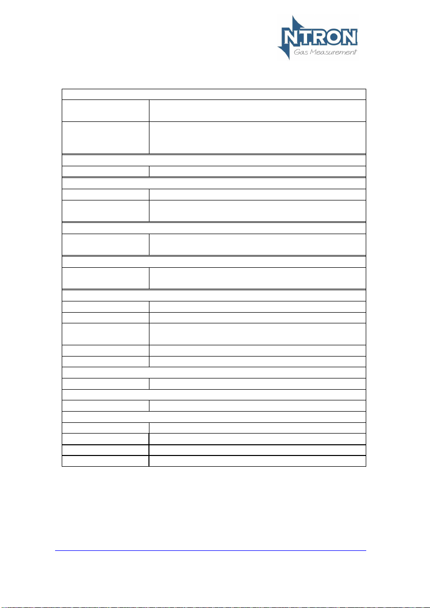
2 SPECIFICATION
Supply
Input Voltage
Options:
2310VAC/24 VDC.
Supply current:
140 mA at 24VDC nominal all relays energised,
20 mA drawn on current loop.
Outputs
Analogue Output:
4-20mA analogue output (10-bit resolution)
Sensor Input
No of Channels:
1
Sensor
%Vol or ppm Zirconia, 3-5Year Life.
Relays
3
Single pole change over.
Rating 6 Amps 250 v AC
Fuses
Fuse
500mA anti-surge on board fuse for circuit
protection.
Additional Features
Display:
4 Digit, 7 Segment Display.
Keypad:
4-Button Keypad
Software:
Software configuration, calibration and data
logging provided by PC communications.
RS232 Output
Weight
1.3Kg
Dimensions
219(265 inc. fittings)x280x156 (LxHxD)
Operating Temp.
-30oC to +400C
Status Indicator
Option.
Two-Lamp Light Tower with Sounder
Red Lamp LED-Alarm (+ Sounder 80db@0.3Mtr)
Page 7
Issue:
V2.3.3.P
Rev. 1.0
Page 5
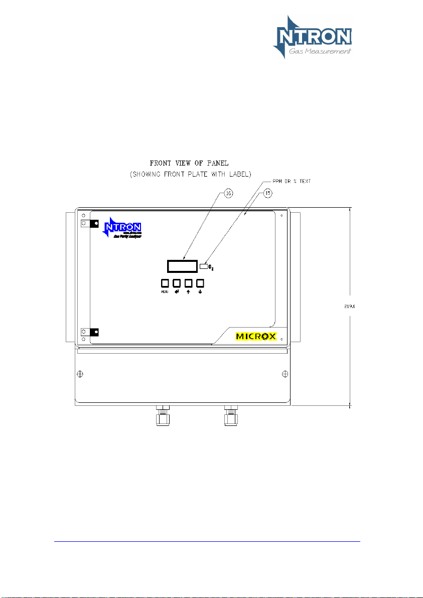
3 PHYSICAL DATA
3.1 Mounting and Dimensions
Fig.1 shows the overall dimensions of the Microx on line.
Page 8
Issue:
V2.3.3.P
Rev. 1.0
Page 6
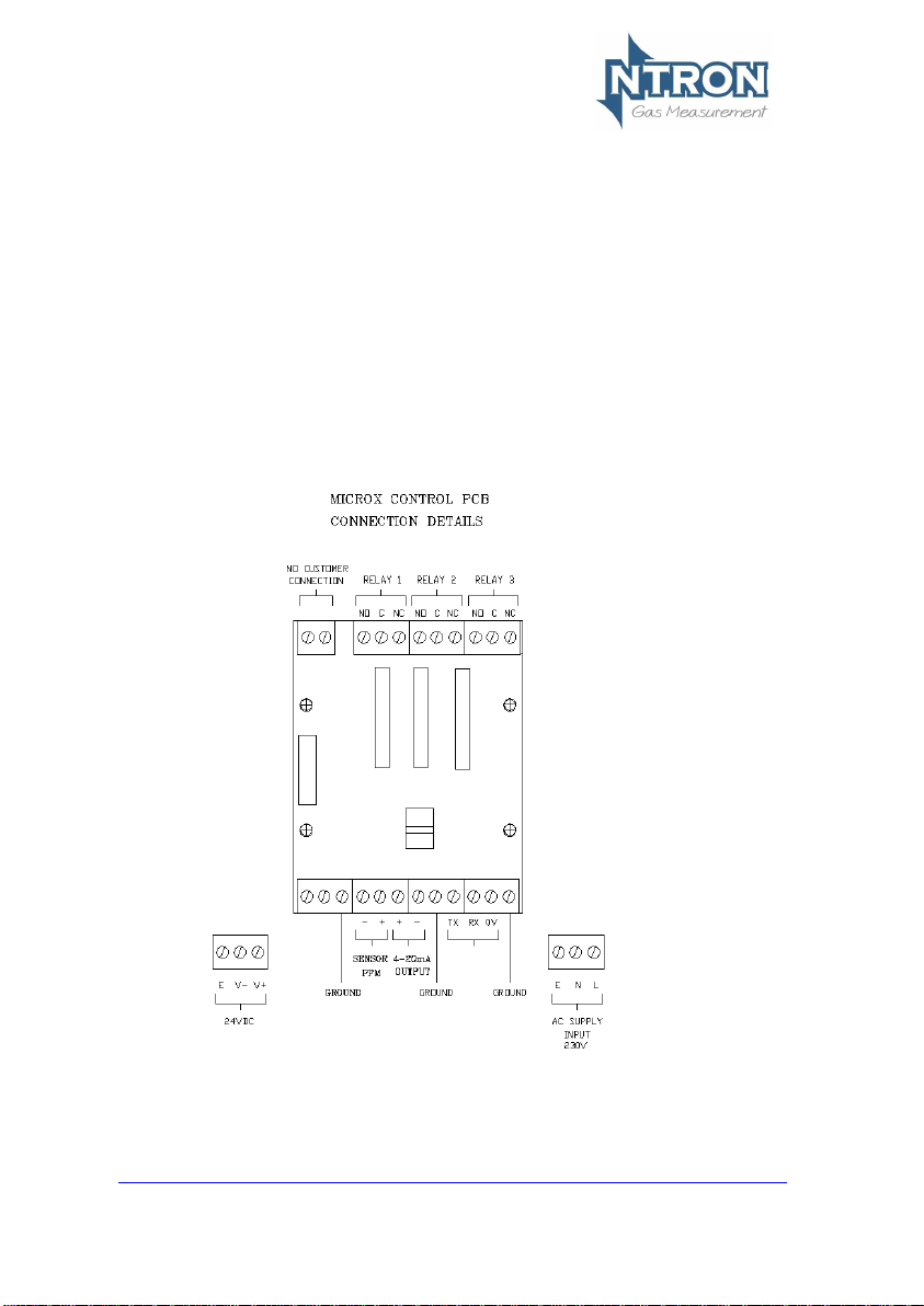
3.1.1 Field Connections
All connections to the module are provided in the form of screw terminals.
Access is gained by opening the Microx Online enclosure to reveal the
terminal connector strips on the rear of the control module backplate
NOTE: Confirm the Voltage supply option of the instrument before connecting
power.(230VAC or 24VDC)
The user field connection points are illustrated below. Cable glands are
provided for power and interface cabling.
The User is to make all field connections in suitable cable to local
regulation codes and taking into account the power requirements of the
instrument as detailed in section 2 (Specification) of this manual.
The AC supply connection should be protected by an upstream protective
device. 24VDC is available at the 24VDC terminals if an AC supply is connected.
If AC mains supply is not available then it is possible to power the unit from
24VDC source via these terminals.
Page 9
Issue:
V2.3.3.P
Rev. 1.0
Page 7
Page 10
Issue:
V2.3.3.P
Rev. 1.0
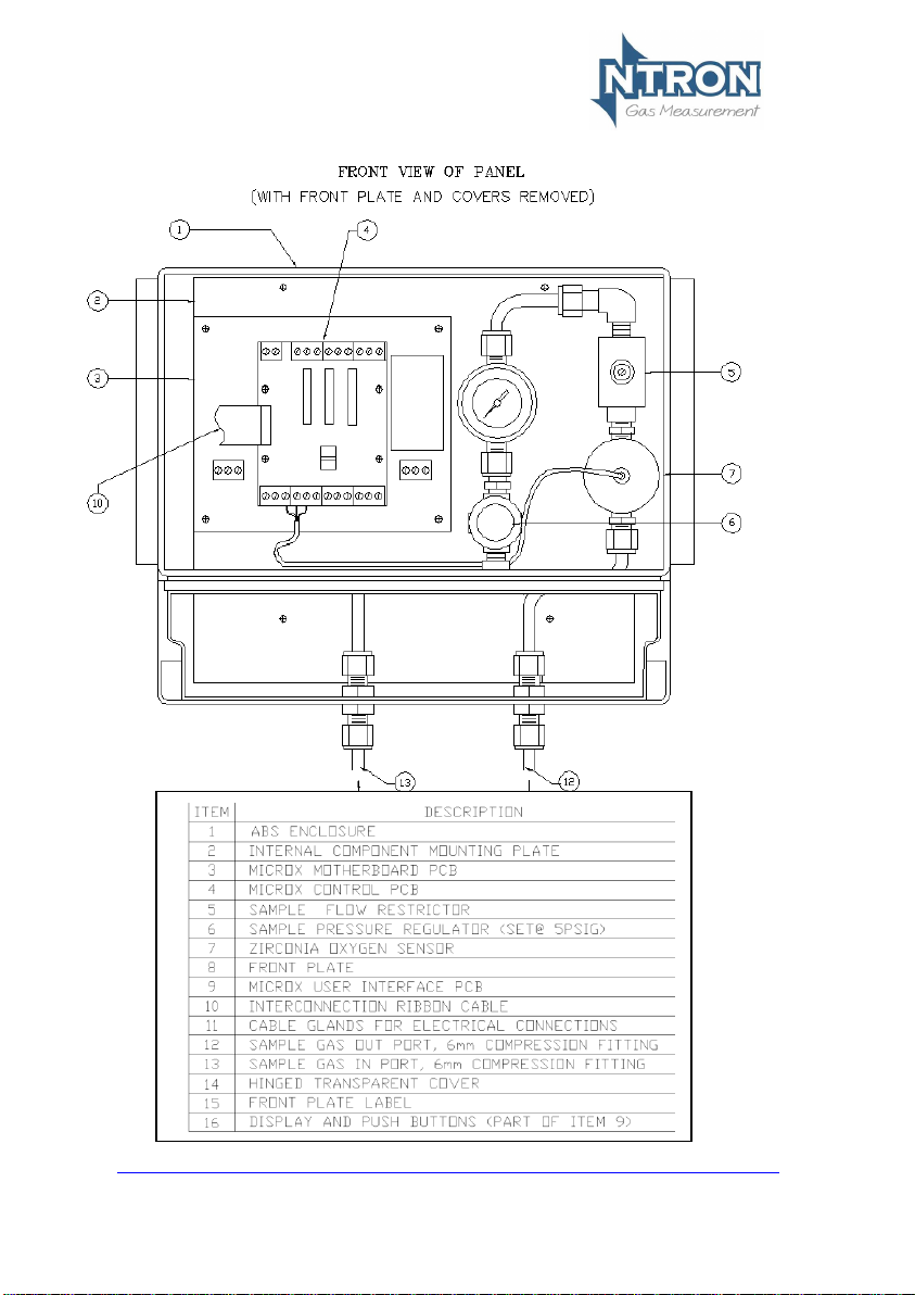
Page 8
Internal layout
Page 11

Issue:
V2.3.3.P
Rev. 1.0
Page 9
3.1.4 Mounting Locations and Installation
The Microx Online is a fixed gas detection system and should be installed so
as to provide effective analysis of a process sample, either at end of line or
from a process pipeline or vessel. The Alarm indication thus rendered by the
Microx Online should be able to initiate the following actions as required:
Indication of ‘Alarm’ level oxygen content.
Shut Down of process or plant.
Alarm relayed back to customer PLC/DCS.
In general, fixed systems should be installed so that maintenance of failure of
one of the instrument does not compromise the safety of the process being
measured.
Factors to take into consideration when choosing a location to mount the
Microx Online:
Location of suitable process sample point.
Visibility of status indicator tower (Light Tower)
Sufficient space on vertical surface or wall for secure mounting and access to
the instrument.
Nature of gas to be measured.
Pressure of gas to be measured at point of sample take-off.
Routing of sample in and exhaust pipework.
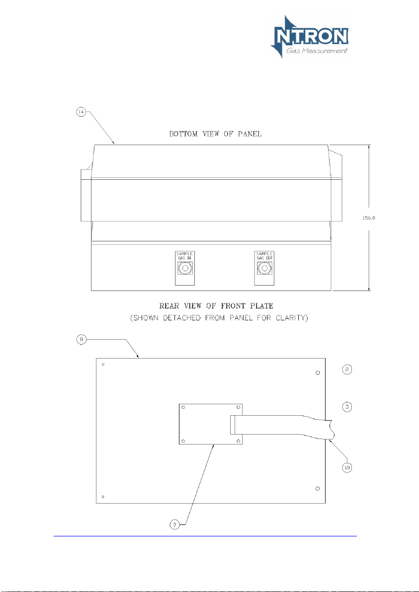
The Microx Online has 6mm Bulkhead Compression fittings for Sample In and
Sample Out(Exhaust) pipe work. Typically the Pipework is of Stainless Steel
but flexible PVC or other tube could be used if space limitations or other
factors favour this.
It is the end user’s responsibility to ensure the correct and suitable pipe or
tube is used for the installation.
Important Wiring note:
If the Light Tower option is fitted (see next page), two of the internal Relays
will be allocated to facilitate the operation of the Light Tower.
In such cases, One relay (Relay 3) will be available for user by the customer
(dry change over contact)
Page 12

Issue:
V2.3.3.P
Rev. 1.0
Page 10
Light Tower Option
The Light tower illustrated above can be fitted to the top of the Microx
OL. It contains a Green and red indicator (for Safe and Alarm
conditions and also an audible Alarm sounder
109mm
Page 13

Issue:
V2.3.3.P
Rev. 1.0
Page 11
3.4 RS232 connections
Microx
PC Connections
Function
Function
9-way ‘D’
25-way ‘D’
TxD
RxD 2 3
RxD
TxD 3 2
0V
0V 5 9
3.5 Analogue Output
The analogue output provides a means of indicating to external equipment
(e.g. data loggers, remote displays) the gas levels currently being detected by
the system. The output is that of a Current Source (4-20mA), where 4mA
represents zero gas and 20mA represents gas at the sensor FSD.
Page 14

Issue:
V2.3.3.P
Rev. 1.0
Page 12
4 SOFTWARE FEATURES
The menu system featured within the Microx Online allows all calibration and
configuration activities to be performed.
A B C D
The keypad has the following functionality:
Button
Function
Alternate Function
A
Menu Open/Close
B
Enter
Numerical value 1
C
Next (Increment)
Numerical value 2
D
Previous (Decrement)
Numerical value 3
4.1 Password
The Microx module uses a password system to restrict the end user from
carrying out certain changes that may compromise the use of the equipment.
The Password feature may be Enabled or disabled.
Menu access is organised in three levels, 1, 2 and 3.
Each of the three menu levels allows access to specific menu options within
the menu system.
When a particular menu level is accessed, the user has 10 seconds to enter a
specific menu within that level otherwise the menu level is automatically
exited. Once a menu is entered, the user then has a duration of 10 minutes
within that menu to make adjustments. When the adjustment is made, the
menu is exited to save the adjusted setting to the analyser memory.
20.9
Page 15

Issue:
V2.3.3.P
Rev. 1.0
Page 13
Menu options
Menu option
Function
E:1
Calibrate Sensor
E:2
Analogue output FSD
E:3
Set 4 mA
E:4
Set 20 mA
E:5
Analogue Output Simulation
E:6
Factory Restore
E:8
Diagnostics
E:9*
Sensor type. (Factory Only)
E:10**
Zero Offset (ppm Sensor only)*
E:11
PPM Sensor Gain
E:12
% Vol Sensor Gain
E:13
Sensor Damping
E:14
New Sensor Data
E:15
Electronic Zero
E:16
Noise Rejection
E:17
Relay
E:18
Alarm Levels
E:19
Alarm Hysteresis
E:20
Password Enable/Disable
*This Menu is protected by an additional factory Password and is not
for use by the end user.
**This Menu is only visible when certain sensor types are fitted.
To access the Menus, first press the MENU button on the Analyser keypad.
The Analyser display will flash with the word PASS. Enter the Password
depending on the menu access required. The numerical Passwords are to be
entered by using the keypad buttons as identified on the previous page.
(e.g. for numerical password 1331, press button ‘B’ then button ‘D’ twice, then
button ‘B’ again.) Note that for access to the Level 1 menus, no password
entry is required. Next, press the MENU button again and press the UP arrow
button to advance through the menu levels.
Page 16

Issue:
V2.3.3.P
Rev. 1.0
Page 14
Password Structure
1.
Level 1
Level 2
Level 3
Password
Password
Password
None
1331
12231
Menu
Menu
Menu
E:1
E:2 E:3 E:3 E:4 E:4
E:5 E:5 E:5
E:6
E:8 E:8 E:8
E:9*
E:10**
E:11
E:12
E:13
E:14
E:15
E:16
E:17
E:17
E:17
E:18
E:18
E:18
E:19
E:19
E:19
E:20
MENU
MENU
MENU
MENU
MENU
MENU
*E:9-Password protected, Factory only; **E:10-visibilty according to sensor type.
Page 17

Issue:
V2.3.3.P
Rev. 1.0
Page 15
4.1.1 Menu 1 – Calibrate sensor
• Press the MENU button to open the menu system.
• Using the NEXT and PREVIOUS buttons select menu option:
E:1
• Press ENTER.
• Apply a known concentration of gas (applicable to sensor type)
at a flow rate of between 100 to 500 ml/m. Allow time for the
sensor to respond. (see diagram on page 8)
• Using the INC and DEC buttons set the reading to that of the
calibration gas level.
• Press ENTER to span the sensor, ‘– – – –‘will be displayed to
confirm the sensor span has been performed.
Note: Pressing the MENU button rather than the ENTER
button exits the span feature without performing the
calibration.
Wait until the reading is stable, if not press the ENTER
button to span the sensor.
• Press the MENU button to close the menu system.
Note: The sensor span setting will be displayed ( as a
percentage value) on exit while the MENU key is pressed.
Note that this value is a percentage of the initial calibration
value set via “New Sensor Data” in menu E:14. See note
below.
• Turn off and disconnect the calibration gas.
Note: On each occasion that a new sensor is connected and calibrated the
“New Sensor Data” should be set via the procedure in menu 14. The
setting should only be carried out after the calibration and not before.
This will ensure that subsequent span setting figures displayed on exit
of menu 1 will be valid.
Page 18

Issue:
V2.3.3.P
Rev. 1.0
Page 16
4.1.2 Menu 2 – Analogue output FSD
• Press the MENU button to open the menu system.
• Using the NEXT and PREVIOUS buttons select menu option:
E:2
• Press ENTER.
• Using the INCREASE and DECREASE buttons adjust the FSD
to the required level.
• Press ENTER.
Note: Pressing the MENU button rather than the ENTER
button exits the sensor FSD feature without any change.
• Press the MENU button to close the menu system.
Note: The Sensor FSD will be displayed on exit while the
MENU key is pressed.
4.1.3 Menu 3 – Set 4 mA output
• Monitor the current sourced from the analogue output of the
OEM module using a multimeter set to read milliamps.
• Press the MENU button to open the menu system.
• Using the NEXT and PREVIOUS buttons select menu option:
E:3
• Press ENTER.
• Using the INCREASE and DECREASE buttons adjust the
output to 4mA .
• Press ENTER.
Note: Pressing the MENU button rather than the ENTER
button exits the 4 mA feature without performing the
calibration.
• Press the MENU button to close the menu system.
Note: The 4 mA factor will be displayed on exit.
Page 19

Issue:
V2.3.3.P
Rev. 1.0
Page 17
4.1.4 Menu 4 – Set 20 mA output
• Monitor the current sourced from the analogue output of the
OEM module using a multimeter set to read milliamps.
• Press the MENU button to open the menu system.
• Using the NEXT and PREVIOUS buttons select menu option:
E:4
• Press ENTER.
• Using the INCREASE and DECREASE buttons adjust the
output to 20 mA.
• Press ENTER.
• Press the MENU button to close the menu system.
Note: The 20 mA factor will be displayed on exit.
4.1.5 Menu 5 – Analogue Output Simulation
The Gasnz analogue output can be tested for functionality via menu 5.
This option allows the user to simulate the analogue output.
• Press the MENU button to open the menu system.
• Using the NEXT and PREVIOUS buttons select menu option:
E:5.
• Use the UP and DOWN button to increase or decrease the
analogue output. The value displayed on the Microx display will
be equivalent to the analogue output.
• Press the MENU button to close the menu system.
Note: The module will return to the conditions on entry.
Page 20

Issue:
V2.3.3.P
Rev. 1.0
Page 18
4.1.6 Menu 6 – Sensor selection
This option allows the user to restore the configuration data to the factory
default values.
Warning
A restore will overwrite all previous calibration data for the selected
sensor excluding those set at the factory.
• Press the MENU button to open the menu system.
• Using the NEXT and PREVIOUS buttons select menu option:
E:6
• Press ENTER button. Hold for 5 or 6 seconds.
• When - - - - is displayed, release the ENTER button.
Note: Pressing the MENU button rather than the ENTER
button exits the restore feature without performing any
change.
• Press the MENU button to close the menu system.
4.1.7 Menu 7
No Function
4.1.8 Menu 8 - Diagnostics
This feature is a view-only feature. No configuration changes are possible from
within this menu.
• Press the MENU button to open the menu system.
• Using the NEXT and PREVIOUS buttons select menu option:
E:8
• Press ENTER.
• The display will alternate between the current value and
diagnostic code E:8x: where x is:
0 Sensor signal, A to D counts low ppm range.
1 Sensor signal, A to D counts high ppm range.
2 Sensor signal, A to D counts %vol range.
3 Firmware version.
• The diagnostic code can be selected by pressing the UP button.
• Press MENU to return the instrument to its standard mode of
operation.
Page 21

Issue:
V2.3.3.P
Rev. 1.0
Page 19
4.1.8 Menu 9
Factory Only
4.1.9 Menu 10
Not Applicable
Page 22

Issue:
V2.3.3.P
Rev. 1.0
Page 20
4.1.11 Menu 11 – PPM sensor Gain
4.1.12 Menu 12 – % vol sensor gain
This option is used to allow the user to adjust the sensor gain for optimal
performance. Care should be taken when using this option, which is normally
only used when a new sensor is fitted.
Warning
Customer adjustment of this setting is not recommended. The module
will be factory set prior to shipment at a value appropriate to the sensor
type fitted. Otherwise changing this value may limit the performance
and, in extreme cases, the instrument may no longer detect gas.
The display alternates between the sensor signal level, indicated as a number
between 0 and 4095, and the menu number, E:11. The value used should be
about 3500.
The display indicates the gain setting when the Up / DOWN keys are pressed.
The gain is between 0 and 31, a typical value would be 3.
Apply 13 mV to the sensor input.
• Press MENU to open the menu system.
• Using the NEXT and PREVIOUS buttons, select menu option:
E:12
• Press ENTER. The display shows the sensor peak output level.
• Use the INCREASE and DECREASE buttons to set the required
signal level.
Note: When the INCREASE and DECREASE buttons are
being operated the display shows the amplifier gain setting
as a number between 0 and 31. The larger the number the
higher the gain, the lower the signal reading.
• Press ENTER to store the new value.
Note: Pressing the MENU button rather than the ENTER button
exits without any change.
• Press MENU to close the menu system.
Note: The signal gain setting will be displayed on exit while
the MENU key is pressed.
Customer adjustment of this setting is not permitted.
Page 23

Issue:
V2.3.3.P
Rev. 1.0
Page 21
4.1.13 Menu 13 – Sensor damping
Oxygen sensors output change when subjected to pressure changes.
The damping option is used to allow the user to reduce the effects of sudden
changes by applying digital filtering. The larger the number the more the signal
damping that is applied.
Note: The minimum setting is 5.
• Press MENU to open the menu system.
• Using the NEXT and PREVIOUS buttons, select menu option:
E:13
• Press ENTER. The display shows the damping factor that is
applied to the sensor.
• Use the INCREASE and DECREASE buttons to set the required
damping level.
• Press ENTER to store the new value.
Note: Pressing the MENU button rather than the ENTER button
exits without any change.
• Press MENU to close the menu system.
Note: The signal damping setting will be displayed on exit
while the MENU key is pressed.
4.1.14 Menu 14 – New sensor data
This option allows the initial sensor calibration data to be set. It is used to
predict the remaining sensor life.
• Press MENU to open the menu system.
• Using the NEXT and PREVIOUS buttons, select menu option:
E:14
• Press ENTER. The display displays E:14
• Press ENTER to store the new data in the memory.
Note: Pressing the MENU button rather than the ENTER button
exits without any change.
• Press MENU to close the menu system.
Page 24

Issue:
V2.3.3.P
Rev. 1.0
Page 22
4.1.15 Menu 15 – Electronics zero
Disconnect the sensor and place a short at the sensor input to simulate 0%
oxygen.
• Press the MENU button to open the menu system.
• Using the NEXT and PREVIOUS buttons select menu option:
E:15
• Press ENTER.
• Press ENTER to zero the sensor, ‘– – – –‘will be displayed to
confirm the sensor zero has been performed.
Note: Pressing the MENU button rather than the ENTER
button exits the zero feature without performing the
calibration.
• Press the MENU button to close the menu system.
Page 25

Issue:
V2.3.3.P
Rev. 1.0
Page 23
4.1.16 Menu 16 – Noise Rejection
Warning
Customer adjustment of this setting is not recommended. The module
will be factory set prior to shipment at a value appropriate to the sensor
type fitted. Otherwise changing this value may limit the performance
and, in extreme cases, the instrument may no longer detect gas.
The unit has a noise rejection value associated with the reading and
displaying of the measured gas level.
The noise rejection value is expressed in number of readings that
must be within approximately 20 counts on the AtoD converter of each
other before the display is updated. It takes a value of between 0 and
9, where 0 is no rejection and 9 is the maximum jejection.
Setting the noise rejection results in a two second delay for quick
changing gas levels.
• Press MENU to open the menu system.
• Using the NEXT and PREVIOUS buttons, select menu option:
E:16
• Press ENTER. The display shows the Noise rejection value.
• Use the UP / DOWN keys to set the desired level.
• Press ENTER to store the new value in the memory.
Note: Pressing the MENU button rather than the ENTER button
exits without any change.
• Press MENU to close the menu system.
Note each range noise rejection differs in the equivalent gas level as
follows:
Range
%vol
Fixed A to D
Counts
Typical span
factor
Equivalent gas
level %vol
0.00 - 0.0200
20
0.05
0.0001
0.02 - 0.1000
20
0.3
0.0006
0.10 – 1.0000
20
3.5
0.0070
0.0 – 5.0
20
0.004
0.08
5.0 – 25.0
20
0.013
0.26
Page 26

Issue:
V2.3.3.P
Rev. 1.0
Page 24
4.1.17 Menu 17 – Relay
The unit is fitted with three relays that are operated in conjunction with one of
three alarm levels.
Relay 1 is associated with alarm level 1.
Relay 2 is associated with alarm level 2.
Relay 3 is associated with alarm level 3.
The user can select if the relay is normally Energized, E’ or normally de-
energised, ‘d’ when the unit is not in an alarm condition. The relay can also be
set to act on rising, ‘r’ or falling ‘F’ gas levels.
This option allows the user to configure the operation of the relays.
• Press MENU to open the menu system.
• Using the NEXT and PREVIOUS buttons, select menu option:
E:17
• Press ENTER. The display displays r:1
• Use the UP / DOWN keys to select the desired relay.
• The display will show the following:
E:r Normally energized, rising alarm
d:r Normally de-energized, rising alarm
E:F Normally energized, falling alarm
d:F Normally de-energized, falling alarm
• The mode of operation can be changed by pressing the UP
button.
• Press ENTER to store the new data in the memory.
Note: Pressing the MENU button rather than the ENTER button exits
without any change.
• Press MENU to close the menu system.
Page 27

Issue:
V2.3.3.P
Rev. 1.0
Page 25
4.1.18 Menu 18 – Alarm levels
Note: When the option of the Light Tower indicator is fitted, Relays 1 or Relays 1 and 2
will be used to operate the Red, Green Lamps and Audible alarm. Thus only Relay 3 is
typically available for customer interface connection. The programming of Relay 3 can
be matched to either Relay 1 or Relay 2 or another Oxygen level setting as required..
This option allows the user to set the operation of the alarm levels. There are
three alarms levels associated with 3 relays.
Alarm level 1 is associated with relay 1.
Alarm level 2 is associated with relay 2.
Alarm level 3 is associated with relay 3.
• Press MENU to open the menu system.
• Using the NEXT and PREVIOUS buttons, select menu option:
E:18
• Press ENTER. The display displays A:1
• Use the UP / DOWN keys to select the desired alarm level.
• Press ENTER. The display shows the alarm level.
• Use the UP / DOWN keys to set the desired alarm level.
• Press ENTER to store the new value in the memory.
Note: Pressing the MENU button rather than the ENTER button
exits without any change.
• Press MENU to close the menu system.
4.1.19 Menu 19 – Alarm hysteresis
The unit has a hysteresis value associated with the alarm levels to
avoid relay chattering as the unit goes in and out of alarm conditions.
The hysteresis value is expressed as a percentage of the alarm set
point and takes a value of between 0 and 10.
• Press MENU to open the menu system.
• Using the NEXT and PREVIOUS buttons, select menu option:
E:19
• Press ENTER. The display shows the hysteresis level.
• Use the UP / DOWN keys to set the desired level.
• Press ENTER to store the new value in the memory.
Note: Pressing the MENU button rather than the ENTER button
exits without any change.
• Press MENU to close the menu system.
Page 28

Issue:
V2.3.3.P
Rev. 1.0
Page 26
4.1.10 Menu 20
The Password function can be enabled or disabled in this Menu.
• Press MENU to open the menu system.
• Using the NEXT and PREVIOUS buttons, select menu option:
E:20
• Press ENTER. The display shows the current status On or Off
• Use the UP / DOWN keys to set the desired status On or Off.
• Press ENTER to store the new value in the memory.
Note: Pressing the MENU button rather than the ENTER button
exits without any change.
Press MENU to close the menu system.
Page 29

Issue:
V2.3.3.P
Rev. 1.0
Page 27
5 Routine Inspection and Maintenance
It is advisable to periodically inspect the Microx module installation:
Clean gas detector head using a clean DAMP cloth.
Inspect the sensor and ensure it is sound and the sensor-housing
aperture is not obstructed (where applicable).
The maximum time interval between routine inspections and should be
assessed by the calibrating personnel and will depend upon the environment
in which the equipment is installed.
Calibration requirements and periods vary depending on sensor type and
application. A reasonable schedule should be arrived at by the user.
Sensors utilising Zirconia Technology
These are very stable over their normal lifespan and usually do not require
regular calibrations. A check on calibration can be made at intervals to suit the
application by the user and if a calibration operation is deemed necessary,
follow the instructions contained in this manual.
Avoid exposing the Sensor to moisture or wetting particularly if the gas being
presented for measurement by the sensor contains condensable vapours or
entraned liquids. Pre-filtering and drying of the gas to be sampled may be
required by the user.
If the Sensor is not powered for any period, then condensable moisture must
be prevented from entering the sample system and reaching the sensing
element.
Other gases to avoid are halogens, organic vapours, H2S and SO4.
Page 30

Issue:
V2.3.3.P
Rev. 1.0
Page 28
Page 31

Issue:
V2.3.3.P
Rev. 1.0
Page 29
 Loading...