

Page 1

The
Ambient Oxygen
Monitor
With
Part Number: 05-680
Electrochemical Sensor
User Instruction Manual
F/W Issue V233P
Issue Date:
01/10/2018
Rev 1.2
Page 2

1. Introduction ................................................................................................................... 3
1.1 Gasenz ................................. ......................................... .................. ............................3
1.2 Operation ................................................................................. ................................... 4
1.2.1 %Vol Sensor ........................ ................................................................................ 5
2. Specification .................................................................................................................. 6
2.1 Status Indicator.........................................................................................................7
3. Mounting and Dimensions ........................... .......................................................... ....8
3.1.1 Field Connections ............................................................................................... 9
3.1.2 Field Connections -DC Supply-Option. Fig.3 ..................................... .......... 10
3.1.3 Field Connections -DC Supply-Option. Fig.4 ................................................. ....11
3.1.4 Mounting Locations .............................................................................................. 12
3.1.5 Analogue Output ........................................................... .................. ......................14
4. Software Features ................................................................. ..................................... 15
4.1 Password .............................................. ........................................................... .........1 5
4.2 Menu options ........................ ...................................................................................16
Menu Structure .......................................... ................... .................................................... 17
4.2.1 Menu 1-Calibrate Sensor ................. .................... ....................................... .....18
4.2.2 Menu 2 - Analogue output FSD...................................... ................................19
4.2.3 Menu 3 - Set 4 mA output .......................... ..................................................... 19
4.2.4 Menu 4 - Set
4.2.5 Menu 5 - Analogue Output Simulation ..........................................................20
4.2.6 Menu 6 - Factory Restore ......................................................... ...................... 21
4.2.7 Menu 8 - Diagnostics.......................................................................... .....22
4.2.8 Menu 14 - New sensor data........................ .................................................... 22
4.2.9 Menu 17 - Rela y
......................................... .................. .................................... 23
4.2.10 Menu 18 - Alarm levels.................................................................................... 24
4.2.11 Menu 19 - Alarm hysteresis .................................................. ..........................25
4.2.12 Menu
5. Routine Maintenance & Servicing ................................ .......................................... 26
5.1 Routine Inspection and Maintenance ..................................................................... 26
20
mA output ............................................................................. 20
20
................................................................................. ............................2 5
Page 3

1. I
NTRODUCTION
1.1 Gasenz
The Gasenz is a wall or surface mounting device has for the monitoring of %
Oxygen volume levels in an Ambient environment.
Key design features are:
•
Sturdy compact enclosure
•
Status indication by means of a two-lamp beacon and sounder
unit.
•
Simple keypad calibration facility (utilising onboard LCD display).
•
4-20mA current source output for gas level indication (10-bit
resolution).
•
Input voltage range, 85-264VAC. PCB mounted screw terminals
for all connections. Option of 24VDC only.
Issue: V233P
Rev. 1.2
Page 3
Page 4

1.2 Operation
When power is first applied to the Gasenz an initialisation procedure is
performed as follows:
•
All the display segments are displayed
•
The software version number is displayed
•
The company name is displayed
•
The sensor type is displayed
•
The display then shows the gas level.
The Gasenz is now operational
Note: The Gasenz Oxygen Monitor is based around the Microx series of
Oxygen Analyser controllers and contains some Menu programming options
which are not relevant to the Gasenz product and its mode of operation.
Such menu's and information are highlighted in this user manual as 'Customer
Access Not Permitted' and other various warnings against adjustment of such
menu options. Please observe these prohibitions to ensure correct operation
of the Gasenz Oxygen Monitor.
The Gasenz Oxygen Monitor is supplied factory configured and calibrated for
correct operation, and apart from sensor replacement and periodic calibration,
should require no further user intervention.
.
Issue: V233P
Rev. 1.2
Page 4
Page 5

1.2.1 %Vol Sensor
A % Volume sensor is an integral part of the Gasenz Monitor.
The % Volume measurement range of the Gasenz Monito
combination is factory set at O to25%, with calibration at 2O.9% 02. (Ambient).
The sensor is disposable, and so requires replacement periodically. (See
maintenance section 5.1 in this user manual)
r/s
ensor
Issue: V233P
Rev. 1.2
Page 5
Page 6
Supply
85-264VA
C
Outp
uts
Sensor Input
Relays
F
uses
Additional Features
2. S
PECI
FIC
ATION
Input Voltage
Options:
140 mA at 24VDC nominal , all relays energised,
20
Supply current:
Analogue Output: 4-20mA analogue output (10-bit resolution)
No of Channels: 1
Sensor %Vol oxygen 0-25% 18 Months life approx.
mA drawn on current loop.
+30mA for integral Sounder Beacon
(Replacement Sensor Part No. 01-335)
. Option of 24 VDC Only.
#1 or 2 (For
user connection)
Fuse
Display: 4 Digit, 7 Segment Display.
Keypad: 4-Button Keypad
Status Indicator Two-Lamp Light Tower with Sounder
Single pole change over.
Rating 6 Amps 250 v AC
500mA anti-surge on board fuse for circuit
protection.
Red Lamp LED-Alarm (+ Sounder 80db
Green Lamp LED-Normal
/Re
ady
@0.
# Depending on Alarm configuration requirements. See page 6.
3Mtr)
Issue: V233P
Rev. 1.2
Page 6
Page 7

2.1 Status Indicator
A Two- Lamp High Intensity LED Light Tower provides indication of Normal
0perational/Ready status or condition (Green) and Alarm condition(Red).
The Alarm condition is triggered by a pre-settable gas measurement level
being reached. At the same time as the Red lamp is illuminated, the Sounder
also operates providing the user with both audible and visual indication of the
alarm condition.
(For setting alarm levels-see page 24)
The Light Tower can be pre-wired for High and Low 02 indication or for Low
02 indication only.
Typical 0perational Settings:
High 02=23% rising alarm.
Low 02= 19% falling alarm.
# If High and Low level alarm functionality is required then only 0ne user
interface relay is available for external connection by the user.
If Low level alarm functionality only is required, then Two user interface relays
remain available for the user to connect to.
Note: The Gasenz will be supplied configured with standard alarm level
settings unless otherwise requested by the user.
For details of standard settings and other options please see the alarm and
Relay configuration section within this manual.
Issue: V233P
Rev. 1.2
Page 7
Page 8
250mm
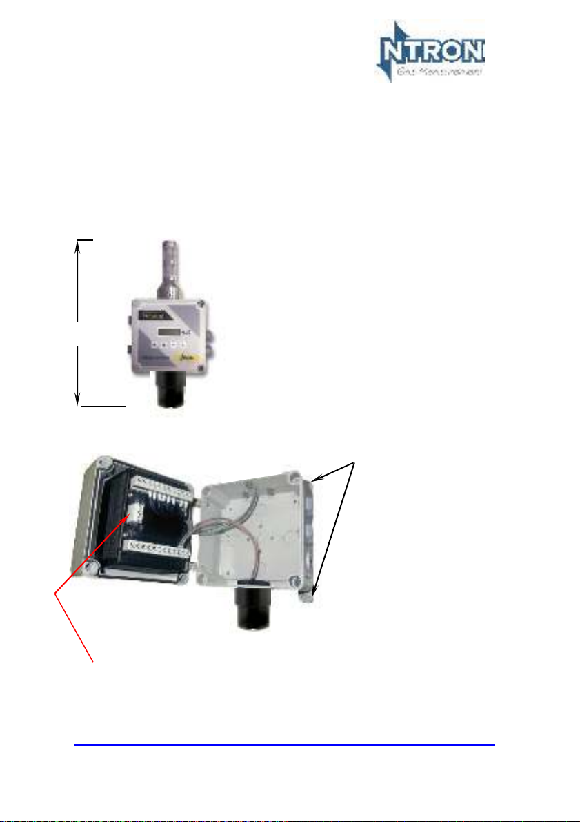
3. M
Fig.1 shows the overall dimensions of the Gasenz.
OUNTING AND DIMENSIONS
Overall dimensions
250mm(H) x 110mm(W) x 93mm(D).
(including Cable Glands)
Fig.1
Control
internal Wiring
Module and
Fig.2
85-264VAC
C
onnection Terminal Strip
supply
Sensor and
internal wiring
Mounting lugs-one per
corner
Issue: V233P
Rev. 1.2
Page 8
Page 9

3.1.1 Field Connections
All connections to the module are provided in the form of screw terminals.
Access is gained by opening the Gasenz enclosure to reveal the terminal
connector strips on the rear of the control module.
NOTE: Confirm the Voltage supply option of the Gasenz before connecting
power.(24VDC or 85-264VAC)
Take care with Mains Voltage when
Connecting and operating the
Monitor. The Door should always be in the
Closed position when operating.
See Fig's 3 and 4 on the following pages for user field connection wiring.
The User is to make all field connections in suitable cable to local
regulation codes and taking into account the power requirements of the
Gasenz as detailed in section 2 (Specification) of this manual.
Issue: V233P
Rev. 1.2
Page 9
Page 10

3.1.2 Field Connections -DC
Supply-Option. Fig.3
*See section 2.1.1 page 6
Relay 3
C
/
N
C
Relay 2 Relay 1
0
/
N
No Connection
Power
In
24VDC
+
_
Internal Wiring to
Light Tower*
I
nternal
Wiring to
Light
Tower
(+/-
24VDC)
-
Output
+
-
+
No
Connection
Ground
Rx
0V
RS232 4-20mA
Tx
Ground
+
-
Ground
Internal wiring
to Sensor (%)
Issue: V233P
Rev. 1.2
Page
10
Page 11

Tx
-
3.1.3 Field Connections -DC
Power
In
85-264VAC N
47-63Hz
*See section 2.1.1 page 6
Relay 3
C
/
N
C
E
L
0V
Ground
RS232
4-20mA
Output
Relay 2 Relay 1
0
/
N
Internal Wiring to
Rx
Ground
Supply-Option. Fig.4
Light Tower*
+
+
-
No
Connection
No Connection
I
Wiring to
24VDC)
Ground
+24vdc out
-24vdc out
nternal
Light
Tower
(+/-
-
+
I
nternal
wiring to
Sensor
(%)
Issue: V233P
Rev. 1.2
Page
11
Page 12

3.1.4 Mounting Locations
The Gasenz is a fixed gas detection system and should be installed so as to provide
effective monitoring of a plant area where a low Oxygen level could occur.
It should be capable of giving an early warning of both the presence and location of an
Oxygen deficient atmosphere.
The Alarm indication thus rendered by the Gasenz should be able to initiate the
following actions as required:
D Safe Evacuation of location or Premises,
D Shut Down of process or plant.
D Ventilation Control.
D Appropriate Fire Fighting Procedures
In general, fixed systems should be installed so that maintenance of failure of one of the
monitoring units does not compromise the safety of the location or premises being
monitored. Duplication of Gasenz units may therefore be appropriate to maintain an
adequate safety level.
Factors to take into consideration when choosing a location to mount the Gasenz are:
D Dimensions of location to be monitored
D Potential leak source
D Nature of gas to be detected
D Possibility of pressurized gas release/evapouration/Liquid leaks
D Confined spaces
D Air movements, ventilation, topography of location, temperature.
D Number of personnel in location.
Issue: V233P
Rev. 1.2
Page
12
Page 13

The densities of gases with respect to air is given in European standard EN
617791:2
temperature and subsequent temporary increase in gas density. In general, Gas
monitors should be installed close to any potential leak source but not so close that they
respond to equipment which may produce inconsequential leakage.
000
. It should be noted that high pressure gas leaks can result in a drop in gas
A well designed ventilation system should result in a number of air changes per hour
and thus limit the potential for a gas build up or depleted Oxygen environment from
developing.
A gas monitor, as a general rule, can cover an area of around 50M2. All applications are
different and require careful consideration before determining the number and location
of gas monitors.
The 50M2 rule equates to approximately a radius of 5M around the gas monitor. If the
gas monitor is mounted on a wall, the operational area is effectively halved. (See
illustrations below)
Issue: V233P
Rev. 1.2
Page
13
Page 14

3.1.5 Analogue Output
The analogue output provides a means of indicating to external equipment
(e.g. data loggers, remote displays) the gas levels currently being detected by
the system. The output is that of a Current Source (4-20mA), where 4mA
represents zero gas and 20mA represents gas at the sensor FSD.
Issue: V233P
Rev. 1.2
Page
14
Page 15

Numeric value of 3
4. S
OFTWARE FEATURES
The menu system featured within the Gasenz allows all calibration and
configuration activities to be performed.
20.9
A B
The keypad has the following functionality:
Function Alternate Function
Button
A Menu Open
B Enter
C Next
D Previous (Decrement)
(In
crement)
4.1 Password
The Gasenz Analyser uses a password system to restrict the end user from
carrying out certain changes that may compromise the use of the equipment.
The Password feature may be Enabled or disabled.
Menu access is organised in three levels, 1, 2 and 3.
Each of the three menu levels allows access to specific menu options within
the menu system.
When a particular menu level is accessed, the user has
specific menu within that level otherwise the menu level is automatically
exited. Once a menu is entered, the user then has a duration of
within that menu to make adjustments. When the adjustment is made, the
menu is exited to save the adjusted setting to the analyser memory.
The menu structure and Password system is explained on the following
pages.
/Cl
ose
c
D
Numeric value of 1
Numeric value of 2
10
seconds to enter a
10
minutes
Issue: V233P
Rev. 1.2
Page
15
Page 16

M
enu opt
ion Functi
o
n
E:11** PPM Sensor Gain
E:12** % Vol Sensor Gain
E:13** Sensor Damping
E
:14 New Sensor D
ata
E:15** Electronic Zero
E:16** Noise Rejection
E
:17 Relay
E
:18 Al
arm L
evels
E
:19 Al
arm
Hysteresis
E
:20 Pass
word
Enable/Disable
4.2 Menu options
E:1
Calibrate Sensor
E:2
Analogue output FSD
E:3
Set 4 mA
E:4
Set
E:5
Analogue Output Simulation
E:6
Factory Restore
E:8
Diagnostics
E:9*
Sensor type. (Factory Only)
20
mA
*This Menu is protected by an additional factory Password and is not for use
by the end user.
** These menus should not be accessed or changed by the user.
Note: there is no Menu 10.
To access the Menus, first press the MENU button on the Analyser keypad.
The Analyser display will flash with the word PASS. Enter the Password depending on
the menu access required. The numerical Passwords are to be entered by using the
keypad buttons as identified on the previous page.
(e.g. for numerical password 1331, press button ‘B’ then button ‘D’ twice, then button ‘B’
again.) Note that for access to the Level 1 menus, no password entry is required. Next,
press the MENU button again and press the UP arrow button to advance through the
menu levels.
Issue: V233P
Rev. 1.2
Page
16
Page 17

Level 2
Pass
word
1331
Menu
E:3
E
:18
E
:19
Level l
E:2
E:3
E:9*
E
:12
E
:13
E
:14
E
:19
E
:20
Level 1
E:8
E
:17
Menu Structure
MENU
PASS
MENU
PASS
1331
MENU
MENU
PASS
12231
MENU
Password
None
Menu
Password
12231
Menu
E:1
MENU
E:4
E:5
E:4
E:5
E:8
E:5
E:6
E:8
E:11
E:15
E:16
E:17
E:18
E:17
E:18
E:19
*E:9-Password protected, Factory only; 'Greyed out' menus should not be accessed.
Issue: V233P
Rev. 1.2
Page
17
Page 18

4.2.1 Menu 1-calibrate Sensor
This can be performed in ambient atmosphere after verification that said
atmosphere is @20.9% Oxygen.
•
Press the MENU button to open the menu system.
•
Using the NEXT and PREVIOUS buttons select menu option:
E:1
•
Press ENTER.
•
Allow time for sensor to respond/stabilise.
•
Using the INC and DEC buttons set the reading to that of the
calibration gas level.
•
Press ENTER to span the sensor, '- - - -'will be displayed to
confirm the sensor span has been performed.
Note: Pressing the MENU button rather than the ENTER
button exits the span feature without performing the
calibration.
Wait until the reading is stable, if not press the ENTER
button to span the sensor.
•
Press the MENU button to close the menu system.
Note: The sensor span setting will be displayed ( as a
percentage value) on exit while the MENU key is pressed.
Note that this value is a percentage of the initial calibration
value set via "New Sensor Data" in menu E:14. See note
below.
Note: On each occasion that a new sensor is connected and calibrated the
"New Sensor Data" should be set via the procedure in menu 14. The
setting should only be carried out after the calibration and not before.
This will ensure that subsequent span setting figures displayed on exit
of menu 1 will be valid.
Issue: V233P
Rev. 1.2
Page
18
Page 19

4.2.2 Menu 2 - Analogue output FSD
•
Press the MENU button to open the menu system.
•
Using the NEXT and PREVIOUS buttons select menu option:
E:2
•
Press ENTER.
•
Using the INCREASE and DECREASE buttons adjust the FSD
to the required level.
•
Press ENTER.
Note: Pressing the MENU button rather than the ENTER
button exits the sensor FSD feature without any change.
•
Press the MENU button to close the menu system.
Note: The Sensor FSD will be displayed on exit while the
MENU key is pressed.
4.2.I Menu I - Set 4 mA output
•
Monitor the current sourced from the analogue output of the
OEM module using a multimeter set to read milliamps.
•
Press the MENU button to open the menu system.
•
Using the NEXT and PREVIOUS buttons select menu option:
E:I
•
Press ENTER.
•
Using the INCREASE and DECREASE buttons adjust the
output to 4mA .
•
Press ENTER.
Note: Pressing the MENU button rather than the ENTER
button exits the 4 mA feature without performing the
calibration.
•
Press the MENU button to close the menu system.
Note: The 4 mA factor will be displayed on exit.
Issue: V233P
Rev. 1.2
Page
19
Page 20

4.2.4 Menu 4 - Set 20 mA output
•
Monitor the current sourced from the analogue output of the
OEM module using a multimeter set to read milliamps.
•
Press the MENU button to open the menu system.
•
Using the NEXT and PREVIOUS buttons select menu option:
E:4
•
Press ENTER.
•
Using the INCREASE and DECREASE buttons adjust the
output to
•
Press ENTER.
•
Press the MENU button to close the menu system.
Note: The 20 mA factor will be displayed on exit.
20
mA.
4.2.5 Menu 5 - Analogue Output Simulation
The Gasnz analogue output can be tested for functionality via menu 5.
This option allows the user to simulate the analogue output.
•
Press the MENU button to open the menu system.
•
Using the NEXT and PREVIOUS buttons select menu option:
E:5.
•
Use the UP and DOWN button to increase or decrease the
analogue output. The value displayed on the Microx display will
be equivalent to the analogue output.
•
Press the MENU button to close the menu system.
Note: The module will return to the conditions on entry.
Issue: V233P
Rev. 1.2
Page
20
Page 21

4.2.6 Menu 6 - Factory Restore
This option allows the user to restore the configuration data to the factory
default values.
Warning
A restore will overwrite all previous calibration data for the selected
sensor excluding those set at the factory.
•
Press the MENU button to open the menu system.
•
Using the NEXT and PREVIOUS buttons select menu option:
E:6
•
Press ENTER button. Hold for 5 or 6 seconds.
•
When - - - - is displayed, release the ENTER button.
Note: Pressing the MENU button rather than the ENTER
button exits the restore feature without performing any
change.
•
Press the MENU button to close the menu system.
Issue: V233P
Rev. 1.2
Page
21
Page 22

4.2.7 Menu 8 - Diagnostics
This feature is a view-only feature. No configuration changes are possible
from within this menu.
•
Press the MENU button to open the menu system.
•
Using the NEXT and PREVIOUS buttons select menu option:
E:8
•
Press ENTER.
•
The display will alternate between the current value and
diagnostic code E:8x: where x is:
O
Sensor signal, A to D counts low ppm range.
1 Sensor signal, A to D counts high ppm range.
2 Sensor signal, A to D counts %vol range.
3 Firmware version.
4 Analyser Serial Number. First four digits
5 Analyser Serial Number. Last four digits.
(The Analyser Serial number comprises typically of 6
numerical digits)
•
The diagnostic code can be selected by pressing the UP button.
•
Press MENU to return the instrument to its standard mode of
operation.
4.2.8 Menu 14 - New sensor data
This option allows the initial sensor calibration data to be set. It is used to
predict the remaining sensor life.
•
Press MENU to open the menu system.
•
Using the NEXT and PREVIOUS buttons, select menu option:
E:14
•
Press ENTER. The display displays E:14
•
Press ENTER to store the new data in the memory.
Note: Pressing the MENU button rather than the ENTER button
exits without any change.
•
Press MENU to close the menu system.
Issue: V233P
Rev. 1.2
Page
22
Page 23

4.2.9 Menu 17 - Relay
Note: Changing these settings (and those in Menu 18) will alter the
operating point of the Indicator unit and Relays and as such may
affect the capability of the unit to announce a dangerous Oxygen
Level to the user. Be sure you understand the intended effects of your
intervention into these Menus.
Relay 1 or 1 and 2 are configured and wired for operation of the Light Tower indication
unit and when so used, are not available for use by the user. Relays not used to operate
the Light Tower are available for user connection. Relay 3 (and Relay 2 if available) are
volt free contacts, 6A @ 250VAC rated.
The unit is fitted with three relays that are operated in conjunction with one of
three alarm levels.
Relay 1 is associated with alarm level 1.
Relay 2 is associated with alarm level 2.
Relay 3 is associated with alarm level 3.
The user can select if the relay is normally Energized, E' or normally deenergised, 'd' when the unit is not in an alarm condition. The relay can also be
set to act on rising, 'r' or falling 'F' gas levels.
This option allows the user to configure the operation of the relays.
•
Press MENU to open the menu system.
•
Using the NEXT and PREVIOUS buttons, select menu option:
E:17
•
Press ENTER. The display displays r:1
•
Use the UP I DOWN keys to select the desired relay.
•
The display will show the following:
E:r Normally energized, rising alarm
d:r Normally de-energized, rising alarm
E:F Normally energized, falling alarm
d:F Normally de-energized, falling alarm
•
The mode of operation can be changed by pressing the UP
button.
•
Press ENTER to store the new data in the memory.
Note: Pressing the MENU button rather than the ENTER button exits
without any change.
•
Press MENU to close the menu system.
Issue: V233P
Rev. 1.2
Page
23
Page 24

4.2.10 Menu 18 - Alarm levels
Relay's 1 and 2 alarm levels are factory configured for 19% Vol. 02 falling (relay
1) and 21% Vol. 02 Rising (relay 2). Relay 1 is set at 25% rising by default.
19.5% is the 0HSHA recognised US lower Alarm level for 02 depletion. Some
users may wish to follow this regulatory body in the application of this and other
alarm level settings.
This option allows the user to set the operation of the alarm levels. There are
three alarms levels associated with 3 relays.
Alarm level 1 is associated with relay 1.
Alarm level 2 is associated with relay 2.
Alarm level 3 is associated with relay 3.
•
Press MENU to open the menu system.
•
Using the NEXT and PREVIOUS buttons, select menu option:
E:18
•
Press ENTER. The display displays A:1
•
Use the UP I DOWN keys to select the desired alarm level.
•
Press ENTER. The display shows the alarm level.
•
Use the UP I DOWN keys to set the desired alarm level.
•
Press ENTER to store the new value in the memory.
Note: Pressing the MENU button rather than the ENTER button
exits without any change.
•
Press MENU to close the menu system.
Issue: V233P
Rev. 1.2
Page
24
Page 25

4.2.11 Menu 19 - Alarm hysteresis
The unit has a hysteresis value associated with the alarm levels to
avoid relay chattering as the unit goes in and out of alarm conditions.
The hysteresis value is expressed as a percentage of the alarm set
point and takes a value of between O and
1O.
Warning Note:
Setting to -1 disables the Relays.
•
Press MENU to open the menu system.
•
Using the NEXT and PREVIOUS buttons, select menu option:
E:19
•
Press ENTER. The display shows the hysteresis level.
•
Use the UP I DOWN keys to set the desired level.
•
Press ENTER to store the new value in the memory.
Note: Pressing the MENU button rather than the ENTER button
exits without any change.
•
Press MENU to close the menu system.
The Password function can be enabled or disabled in this Menu.
4.2.12 Menu 20
•
Press MENU to open the menu system.
•
Using the NEXT and PREVIOUS buttons, select menu option:
E:20
•
Press ENTER. The display shows the current status On or Off
•
Use the UP I DOWN keys to set the desired status On or Off.
•
Press ENTER to store the new value in the memory.
Note: Pressing the MENU button rather than the ENTER button
exits without any change.
•
Press MENU to close the menu system.
Issue: V233P
Rev. 1.2
Page
25
Page 26

5. R
OUTINE MAINTENANcE
& S
ERVIcING
The Gasenz will provide reliable and fault free service when given regular
maintenance and calibrations.
5.1 Routine Inspection and Maintenance
It is advisable to periodically inspect the Gasenz installation:
Clean gas detector head using a clean DAMP cloth.
Inspect the sensor and ensure it is sound and the sensor-housing
aperture is not obstructed (where applicable).
The maximum time interval between routine inspections should be assessed
by the calibrating personnel and will depend upon the environment in which
the equipment is installed.
Replacement of Sensor
The stated life of the Oxygen sensor is 18 Months under normal operating
conditions.
At the expiry of this period, or at shorter periods for plannedlpreventative
maintenance, the sensor will need replacing.
Remove the two Allen-headed screws and
withdraw this portion of the outer casing to
reveal the sensor. The sensor simply unplugs
from the internal circuit boards and the new
sensor plugs into the same location. Replace
the outer casing and observe the user manual
instructions for sensor calibration.
Issue: V233P
Rev. 1.2
Page
26
Page 27

Sensor disposal.
This instrument utilises an Electro-chemical Sensor, which contains
corrosive electrolyte and must not be opened or sealed membranes
removed. Eye and hand protection must be worn if the sensor is leaking.
Wipe and flush any electrolyte spilt on surfaces. Electrolyte can be fatal
if swallowed.
Do not dispose of into normal waste, but dispose of according to local
codes.
Issue: V233P
Rev. 1.2
Page
27
Page 28

contact
Mullaghboy Industrial Park,
Navan,
Ireland.
Pn.: 00151(0)46 9071111
Fx.: 00151(0)46 9071111
E-mail: lnfo@ntron.com
Web.: www.ntron.com
Ntron at:
county
Meath,
lssue: V233P
Rev. 1.1
Page 28
 Loading...