


Operating instructions
Edition V3-6-5.2

Inhalt |
|
|
1. |
Important notes ............................................................................................................................................. |
3 |
1.1 |
General safety guidelines............................................................................................................................. |
3 |
1.2. |
Used symbols............................................................................................................................................... |
4 |
1.3 |
Intendend use............................................................................................................................................... |
5 |
1.4 |
Short description .......................................................................................................................................... |
5 |
1.5 |
Combination with other products .................................................................................................................. |
5 |
1.6. |
Hygiene standards ....................................................................................................................................... |
6 |
1.7 |
Standards and guidelines............................................................................................................................. |
6 |
1.8 |
Terms ........................................................................................................................................................... |
6 |
2. |
Scope of delivery .......................................................................................................................................... |
7 |
2.1 |
Basic unit...................................................................................................................................................... |
7 |
2.2 |
Equipment .................................................................................................................................................... |
7 |
2.3 |
Accessories, consumables, spare parts, service partner ............................................................................. |
7 |
3. |
Warranty ....................................................................................................................................................... |
7 |
4. |
EMC Notice................................................................................................................................................... |
7 |
4.1 |
Guidance and manufacturer’s declaration – electromagnetic emissions...................................................... |
8 |
4.2 |
Guidance and manufacturer’s declaration – electric immunity ..................................................................... |
9 |
4.3Electromagnetic Environmental Recommendations - Separation distances between portable and mobile
|
RF communications equipment and DENTALONE ................................................................................................ |
11 |
|
|
4.4 |
Essential performance................................................................................................................................ |
11 |
5. |
Environmental conditions............................................................................................................................ |
12 |
|
6. |
Storage and transport ................................................................................................................................. |
12 |
|
7. |
Use and removal of transport cover .......................................................................................................... |
13 |
|
8. |
Use ............................................................................................................................................................. |
14 |
|
|
8.1 |
Description of components......................................................................................................................... |
14 |
|
8.2 |
Preparation / initial operation...................................................................................................................... |
15 |
|
8.3 |
Filling the water tank .................................................................................................................................. |
16 |
|
8.4 |
Completion and arrangement of instruments.............................................................................................. |
17 |
|
8.5 |
Operating elements / displays .................................................................................................................... |
18 |
|
8.6 |
Instruments................................................................................................................................................. |
18 |
|
8.6.1 |
Straight handpieces and contra-angles *)............................................................................................. |
19 |
|
8.6.2 |
Brushless motor Ti-Max NLX-nano....................................................................................................... |
19 |
|
8.6.3 |
Ultrasrasonic scaler VARIOS 170 LUX................................................................................................. |
20 |
|
8.6.4 |
Multifunction syringe ............................................................................................................................. |
22 |
|
8.6.5 |
Suction.................................................................................................................................................. |
23 |
9. |
Cleaning, maintenance, disinfection and sterilization.................................................................................. |
23 |
|
|
9.1. General............................................................................................................................................................ |
24 |
|
|
9.2. Disinfection, cleaning and sterilization of instruments and handpieces ........................................................... |
24 |
|
|
9.3. Cleaning and sterilization of drills and abrasive bodies ................................................................................... |
25 |
|
|
9.4. Cleaning of surfaces which cannot be sterilized.............................................................................................. |
25 |
|
|
9.5. Water pipes and water tank............................................................................................................................. |
25 |
|
|
9.6. Suction system ................................................................................................................................................ |
26 |
|
|
9.7. Recommended disinfection and cleaning agent .............................................................................................. |
26 |
|
10. |
Maintenance.......................................................................................................................................... |
26 |
|
|
10.1. |
Regular maintenance works ................................................................................................................. |
26 |
|
10.2. |
Maintenance intervals........................................................................................................................... |
26 |
|
10.3. Maintenance of the compressed air reservoir................................................................................................ |
27 |
|
|
10.4. Replacing the hand piece cords .................................................................................................................... |
27 |
|
11. |
Malfunctions and trouble-shooting......................................................................................................... |
28 |
|
|
11.1. Fault diagnosis .............................................................................................................................................. |
28 |
|
|
11.2. Fault signals ................................................................................................................................................. |
29 |
|
|
11.3. |
Change of fuse ..................................................................................................................................... |
29 |
|
11.4 |
Manual unlocking the console .............................................................................................................. |
30 |
12. |
Disposal advices ................................................................................................................................... |
30 |
|
13. |
Technical data ....................................................................................................................................... |
31 |
|
Annex A.................................................................................................................................................................. |
|
33 |
|
|
Operation manual Multi-control panel..................................................................................................................... |
33 |
|
Annex B................................................................................................................................................................. |
|
43 |
|
|
Operation manual Ultrasonic Scaler Varios 170..................................................................................................... |
43 |
|
Annex C ................................................................................................................................................................. |
|
52 |
|
|
Operation manual Micromotor NLX nano ............................................................................................................... |
52 |
|
Page 2 of 54

1. Important notes
In order to get to know the advantages of the treatment unit and to guarantee patient safety it is absolutely necessary to thoroughly read the instructions for use before putting the device into operation.
1.1General safety guidelines
1The unit is built under consideration of the requirements of the German Act of Medical Devices or the guideline 93/42/EWG for medical devices and meets the essential requirements of annex I. The product is a device of class IIa according to annex IX of regulation 9 of guideline 93/42/EEC for medical devices.
2The safety technical standard is based on the VDE-regulation for electromedical devices DIN IEC 60601 part 1 / DIN VDE 0750 part 1.
3Caution: To avoid the risk of electric shock, the device is to be connected with supply networks which are installed according to the regulations for medically used rooms (IEC 60364-7- 710:2002-11 or DIN VDE 0100-710).
4The device has to be located in such a way, that a separation from the mains by pulling the mains
plug is easily possible in the event of a fault.
5The product is a medical device and must be used in accordance with the rules of the medical devices Act (MPG) by authorized personnel only. The user must guarantee proper handling due to his education or skills and be familiar with the operation of the device.
6Before operating the unit, the user must ensure the reliability and orderly condition of the device. 7 For safety reasons, the equipment must remain switched off when it is unattended. In that case
the power switch is always to be turned off.
8The unit is not suitable for operation in potentially explosive areas
9The product is subject to regular safety checks. The medical devices Act (MPG) and the corresponding regulations are to be observed by the operator fully.
Scope and deadlines of the technical safety checks are prescribed as follows:
At least every 12 months must be carried out following listed safety controls in compliance with DIN VDE 0750 and DIN VDE 0751 like perform:
Visual inspection of device and accessories, protection ground conductor checking according to DIN VDE 0751, equivalent leakage current measurement according to DIN VDE 0751, functional testing of the unit in accordance with the accompanying documents.
We recommend keeping a medical book in which the test results of the safety checks are documented.
10As manufacturer of the device, we can assume responsibility for the safety properties of the unit only if maintenance and repair is performed by us or an authorised agent, if the prescribed service intervals are observed and the device is used in accordance with the operating instructions.
A further condition is that components, affecting the safety of the device, are replaced only with original parts.
Technical service documents are available for companies authorized by us for the service and repair.
11 Warning: Any change of the device is NOT permitted.
12 In case of maintenance, inspection or repair you should request a certificate of type and scope of work of the company. The certificate must contain the date of implementation, as well as name of the company with signature (see also MDD, DIN VDE 0750 / DIN VDE 0751).
13 The user has to comply with all valid laws and directives for medical devices as well as national regulations, in particular, the work safety regulations and accident prevention measures
14 Portable communication devices which emit radio waves (E.g. mobile phones) can affect the medical equipment. Don’t use such devices near the Dentalone (refer page 8, table 4.3 )
15 The instruments Motor, Scaler and Syringe are equipped with LED light. Eye damage may result if the LED is directed straight into the eyes. Do not look into or turn it to the eyes of the patient.
Page 3 of 54

1.2.Used symbols
Caution – check for specific warnings or precautions!
Read the instructions for use!
Caution line voltage!
A disposal through household waste/residual waste is not allowed. Note recycling information!
Application components type B: device with earth connection
Manufacturer
IP30 Device is protected against penetration of solid bodies > 2,5 mm;
Device is protected against dripping water. Vertically falling dripping water may not have any adverse effect.
Don’t tread on! Do not overload!
Do not use outside closed rooms!
Autoclavable on max. 135°C
Direction up
Protect from moisture
Recycleable
Caution fragile!
Handle with care!
 Conformity according to all European Directives
 Temperature limits for storage and transport
 Limits of humidity for storage and transport
 Limits of atmospheric air pressure for storage and transport
Page 4 of 54

1.3Intended use
 The device Dentalone is a portable dental treatment unit and is used for outpatient and stationery general treatment of teeth.
The product is designed only for dental use by qualified personnel.
The NLX nano motor is for cutting / polishing as required during general dental treatment.
The Scaler Varios 170 generates ultrasonic waves intended for use in dental applications such as scaling, root canal treatment, periodontal and cavity preparation.
For the choice of the treatment locations the information in the operating instructions are decisive.
Contra-Indication:
Dentalone: The device should NOT be used for surgical, oral surgical treatments and implant surgery.
Scaler:
1.4Short description
Dentalone is a self-contained dental unit with an integrated water and compressed air supply as well as a low volume suction. The essential features include:
Mobile unit
Ergonomic design due to height-adjustable console
Compact construction, minimal space requirement.
Equipped with Ultrasonic Scaler, Electric Micro-motor, Multifunction syringe and Saliva ejector.
LED Light on Motor, Scaler and Multifunction syringe for better illumination of the treatment area
Motor control with stable tractive power in each speed range.
Ergonomic operation of handpieces/ contra-angles in combination with NLXnano electric micromotor.
No suck-back spray supply on micro-motor, ultrasonic scaler and multifunction syringe.
Clearly arranged work console with integrated swivelling instrument holder, centrally arranged multi-function control panel and storage space for accessories.
Automatic instrument recognition of active instrument
Clearly visible graphic display of the device status and the set parameter
Quick release connection of all instrument hoses for easy exchange
Easy-care housing
Base with wheels combined with the cover and integrated telescopic handle makes transport comfortable as a trolley
1.5Combination with other products
The dental micro-motor NLXnano can be used with instruments from NSK, but also with instruments from other manufacturers with E-type fitting.
Furthermore there is no intended combination with other products.
The ultrasonic scaler Varios 170 should be used exclusively with the correct tips from NSK.
The multi-function syringe should only be used with tips of the manufacturer.
The saliva ejector can be used with any 6 mm or ¼” tips which are approved as dental consumables (CE sign).
For all accessories and consumables the hygiene regulations of the manufacturer shall apply.
Page 5 of 54

1.6.Hygiene standards
1All objects which get into the oral cavity of a patient have to be pre-treated to avoid any infection with any disease.
2All objects which directly or indirectly get in touch with the mouth of the patient are regarded as contaminated. Contaminated objects MUST NOT get in contact with other patients without any disinfection/sterilization.
3Direct unprotected contact with saliva or blood has to be avoided.
For your own safety you MUST, wear suitable protective equipment during the treatment in accordance with country-specific occupational safety and health regulations, E.g. gloves, goggles and face mask.
4It is extremely important that any patient treatments planned in advance, thus all necessary objects are available at the beginning of the treatment to save time and reduce the risk of cross contamination.
5To avoid cross contamination clean and dirty instruments must be kept separately.
6All objects, which are directly or indirectly in contact with the patient, must be either professionally disposed of following treatment or they need to be processed for cross infection control
7The water tank should be filled with of drinking water quality or treated (purified) water. As an additive the product ALPRON is recommended.
1.7Standards and guidelines
Standard |
Contents |
2006/42/EC |
Machinery Directive |
93/42/EC |
Medical Device Directive |
DIN EN 1041 |
Information supplied by the manufacturer of medical devices |
DIN EN 60529 |
Degrees of protection provided by enclosures ( IP-Code ) |
IEC 60601-1 |
Medical electrical equipment; - Part 1: General requirements for safety |
IEC 60601-1-2 |
Medical electrical equipment; Part 1: Electromagnetic compatibility |
DIN EN 62304 |
Medical device software - Software life-cycle processes |
IEC 60601-1-6 |
Medical electrical equipment - Collateral standard: Usability |
DIN EN 980 |
Graphical symbols for use in the labelling of medical devices |
DIN EN ISO 10993-1 |
Biological evaluation of medical devices |
DIN EN 14971 |
Medical devices - Application of risk management to medical devices |
EN ISO 7494-1 |
Dentistry - Dental units - Part 1 General requirements and test methods |
EN ISO 7494-2 |
Dentistry - Dental units - Part 2 Water and air supply |
DIN EN ISO 14457 |
Dentistry – Handpieces and motors |
DIN EN ISO 22374 |
Dentistry - Dental handpieces - Electrical-powered scalers and scaler tips |
EN ISO 10079-3 |
Medical suction equipment - Part 3: Suction equipment powered from a |
|
vacuum or pressure source |
1.8 Terms |
|
Term |
Description |
EMC |
Electromagnetic Compatibility |
Instrument |
Applied part |
Page 6 of 54

2. Scope of delivery
2.1Basic unit
The scope of delivery of the basic unit additionally includes the following components:
1 piece |
Cover with telescopic handle |
1 piece |
Water tank incl. screw cap |
1 piece |
Waste container incl. screw cap with integrated filling level sensor |
1 piece |
Power Cord with non-heating apparatuses plug |
1 piece |
Instruction for use |
1 piece |
Foot pedal |
Accessories (not in the sense of the directive)
Motor: 1 piece Autoclave plug
1 piece Motor Cap for autoclave 1 set O-Rings (3 x black o-rings) 1 piece O-Ring blue
Scaler: 1 piece Sterilization cassette 3 piece Tip Wrench
1 piece Scaler Tip type G4
1 piece Scaler Tip type G6
1 piece Scaler Tip type G8
2 pieces O-Ring
2.2Equipment
(Instrument holder equipped from the left to the right side)
Scaler with light “VARIOS 170 LUX” (separately packed)
Micromotor NLX nano with light (without handpiece/contra-angle *)
Multi-function Syringe
Saliva ejector (without cannula)
2.3Accessories, consumables, spare parts, service partner
Consult your NSK-dealer for more information about specifications, accessories, consumables, spare parts and service partners.
3. Warranty
The manufacturer's warranty is 1 year from date of purchase for provided the unit has been properly commissioned and used in appropriate conditions. The manufacturer reserves the right to determine the cause of any problems and to analyze.
Consumables parts and wearing parts are not covered by the warranty. The warranty will lapse,
-if non-approved materials and liquids as described in the instruction for use are being used,
-if any modification on the unit is made by the customer or other unauthorized persons,
-if the device is used for any other purpose as its intended use,
-if damage is caused by gross negligence or due to improper use.
4.EMC Notice
 The DENTALONE is subject to special precautions regarding EMC and must therefore be installed and used according to the EMC notes in this operation manual.
The Dentalone may cause radio interference or it can interfere with the operation of devices in the vicinity. If the location in which the DENTALONE is used exceeds the applicable RF compliance level mentioned above, the DENTALONE should be checked to verify normal operation. If abnormal performance is observed, additional measures may be necessary, such as reorienting or relocating the DENTALONE.
Portable and mobile RF communications equipment can affect the DENTALONE.
The following cables / components are part of the DENTALONE and can be used exclusively on the DENTALONE (except power cord):
Page 7 of 54

Component |
Ident number |
|
Cable type |
length |
|
|
|
|
|
|
|
Power cord |
|
31338.1 |
H05VV-F 3x0.75mm2 unshielded |
2,0 m |
|
|
|
|
|
|
|
Scaler cord |
VALux-SC |
37075 |
2x0.25mm2 unshielded + 2x0.16mm2 |
1,2 m |
|
|
|
|
unshielded |
|
|
Motor cord |
NLX CD |
37074 |
3x0.25mm2 unshielded + 2x0.16mm2 |
1,2 m |
|
|
|
|
unshielded |
|
|
Multifunction syringe |
57066 |
2x0.25mm2 |
unshielded |
1,2 m |
|
|
|
|
|
|
|
Foot switch |
|
37100 |
4x0.16mm2 |
unshielded |
2,0 m |
|
|
|
|
|
|
Scaler VA2-LUX-HP |
E351050 |
|
|
|
|
|
|
|
|
|
|
Motor NLX nano |
E1044051 |
|
|
|
|
|
|
|
|
|
|
Use of other cables may result in increased emissions or decreased immunity.
4.1Guidance and manufacturer’s declaration – electromagnetic emissions
The DENTALONE is intended for use in the electromagnetic environment specified below.
The customer or the user of the DENTALONE should assure that it is used in such an environment.
Emissions test |
Compliance |
Electromagnetic environment - guidance |
|
|
|
RF emissions |
Group 1 |
The DENTALONE uses RF energy only for its |
CISPR 11 |
|
internal function. |
|
|
Therefore, RF emissions are very low and are not |
|
|
likely to cause any interference in nearby electronic |
|
|
equipment. |
RF emissions |
Class B |
The DENTALONE is suitable for use in all |
CISPR 11 |
|
establishments, including domestic establishments |
Harmonic emissions |
Class A |
and those directly connected to the public low – |
IEC 61000-3-2 |
|
voltage power supply that supplies buildings used |
Voltage fluctuation / |
Complies |
for domestic purposes. |
Flicker emissions |
|
|
IEC 61000-3-3 |
|
|
Page 8 of 54

4.2Guidance and manufacturer’s declaration – electric immunity
The DENTALONE is intended for use in the electromagnetic environment specified below.
The customer or the user of the DENTALONE should assure that it is used in such an environment.
Immunity Test |
IEC 60601-1-2 |
Compliance |
Electromagnetic environment - |
|
|
Test level |
level |
guidance |
|
Electrostatic discharge |
± 6 kV contact |
± 6 kV contact |
Floors should be wood, concrete, |
|
(ESD) |
± 8 kV air |
± 8 kV air |
or ceramic tile. If floors are |
|
IEC 61000-4-2 |
|
|
covered with synthetic material, |
|
|
|
|
the relative humidity should be at |
|
|
|
|
least 30% |
|
Electrical fast transient |
± 1 kV |
± 1 kV |
Mains power quality should be |
|
/ |
for input / output |
for input / output |
that of a typical commercial or |
|
burst |
lines |
lines |
hospital environment |
|
IEC 61000-4-4 |
± 2 kV |
± 2 kV |
|
|
|
for power supply |
for power supply |
|
|
|
lines |
lines |
|
|
Surge |
± 1 kV |
± 1 kV |
Mains power quality should be |
|
IEC 61000-4-5 |
differential mode |
differential mode |
thatof a typical commercial or |
|
|
± 2 kV Common |
± 2 kV |
hospital environment |
|
|
mode |
Common mode |
|
|
Voltage dips, short |
<5% UT for 0.5 cycle |
<5% UT for 0.5 cycle |
Mains power quality should be |
|
interruptions and |
(>95% dip in UT) |
(>95% dip in UT) |
that of a typical commercial or |
|
voltage variations on |
hospital environment. |
|||
40% UT for 5 cycles |
40% UT for 5 cycles |
|||
power supply input |
|
|||
lines |
(60% dip in UT) |
(60% dip in UT) |
Compliance is dependent on the |
|
IEC 61000-4-11 |
70% UT for 25 cycles |
70% UT for 25 cycles |
operator following recommended |
|
|
charging and maintenance of the |
|||
|
|
|
||
|
(30% dip in UT) |
(30% dip in UT) |
installed battery backup |
|
|
<5% UT for 5 |
<5% UT for 5 seconds |
|
|
|
seconds |
(>95% dip in UT) |
|
|
|
(>95% dip in UT) |
|
|
|
|
|
|
|
|
Power frequency |
3 A/m |
3 A/m |
Power frequency magnetic fields |
|
(50/60 Hz) magnetic |
|
|
should be at level characteristic of |
|
field |
|
|
a typical location in a typical |
|
IEC 61000-4-8 |
|
|
commercial or hospital |
|
|
|
|
environment |
NOTE: UT is the A.C. mains voltage prior to application of the test level.
Page 9 of 54

Guidance and manufacturer’s declaration – electromagnetic immunity
The DENTALONE is intended for use in the electromagnetic environment specified below.
The customer or the user of the DENTALONE should assure that it is used in such an environment.
Immunity Test |
IEC 60601-1-2 |
Compliance |
Electromagnetic environment - |
|
|
Test level |
|
|
guidance |
|
|
|
|
|
Conducted RF |
3 V rms |
3 V |
Portable and mobile RF |
|
IEC 61000-4-6 |
150 kHz to 80 MHz |
|
communications equipment should |
|
|
outside |
|
be used no closer to any part of the |
|
Radiated RF |
ISM bands a) |
|
Avea Ventilator, including cables, |
|
IEC 61000-4-3 |
3 V rms |
|
than the recommended separation |
|
|
3 V/m |
distance calculated from the |
||
|
150 kHz to 80 MHz |
|
equation applicable to the |
|
|
In ISM bands a) |
|
frequency of the transmitter. |
|
|
|
|
Recommended separation distance: |
|
|
|
|
d= 1,17 |
P |
|
|
|
d= 1,17 |
P |
|
|
|
on 80 MHz until 800 MHz |
|
d= 2,33  P
P
on 800 MHz until 2,5 GHz Where is P the maximum output power rating of the transmitter in watts (W) according to the
transmitter manufacturer and is the recommended separation distance in meters (m). a)
Field strengths from fixed RF transmitters, as determined by an electromagnetic site survey, c should be less than the compliance level in each frequency range. b) Interference may occur in the vicinity of equipment marked
with the following symbol:  Note 1: At 80 MHz and 800 MHz, the higher frequency range applies.
Note 2: These guidelines may not apply in all situations. Electromagnetic propagation is affected by absorption and reflection from structures, objects and people.
a) Field strengths from fixed transmitters, such as base stations for radio (cellular/cordless) telephones and land mobile radios, amateur radio, AM and FM radio broadcast and TV broadcast cannot be predicted theoretically with accuracy. To assess the electromagnetic environment due to fixed FR transmitters, an electromagnetic site survey should be considered. If the measured field strength in the location in which the DENTALONE is used exceeds the applicable RF compliance level above, the DENTALONE should be checked to verify normal operation. If abnormal performance is observed, additional measures may be necessary, such as reorienting or relocating the DENTALONE.
b) Over the frequency range 150 kHz to 80 MHz, field strengths should be less than 3 V/m.
Page 10 of 54
4.3Electromagnetic Environmental Recommendations - Separation distances between portable and mobile RF communications equipment and DENTALONE
DENTALONE is intended for use in an electromagnetic environment in which radiated RF disturbances are controlled. The customer or the user of the DENTALONE can help prevent electromagnetic interference by maintaining a minimum distance between portable and mobile RF communications equipment (transmitters) and the DENTALONE as recommended below, according to the maximum output power of the communications equipment.
Rated maximum output |
Separation distance according to frequency of transmitter (m) |
||
power of transmitter (W) |
150 kHz to 80 MHz |
80 MHz to 800 MHz |
800 MHz to 2,5 GHz |
|
d=1,17 P |
d=1,17 P |
d=2,33 P |
0,01 |
0,12 |
0,12 |
0,23 |
0,1 |
0,37 |
0,37 |
0,74 |
1 |
1,17 |
1,17 |
2,33 |
10 |
3,7 |
3,7 |
7,3 |
100 |
11,7 |
11,7 |
23,3 |
For transmitters rated at a maximum output power not listed above, the recommended separation distance in metres (m) can be determined using the equation applicable to the frequency of the transmitter, where is the maximum output power rating of the transmitter in Watts (W) according to the transmitter manufacturer.
Note1. At 80 MHz and 800 MHz, the separation distance of the higher frequency range applies. Note2. These guidelines may not apply in all situations. Electromagnetic propagation is affected by absorption and reflection from structures, objects and people.
4.4Essential performance
In accordance with EN 60601-1-2, section 6.2.1.10 are essential features, which under the terms of the immunity guarantee fault-free device functions of the DENTALONE as listed below:
Function of
-Supply of compressed air
-Control of micro-motor
-Control of ultrasonic scaler
-Operation function multi pad
-Suction of saliva ejector
-Automatic detection of removal of the instruments in operation
Page 11 of 54

5. Environmental conditions
Operation |
|
+15to +40 |
|
Temperature area |
|
°C |
|
Relative air humidity, non-condensing, no tropical protection |
30to75 |
% |
|
Air pressure |
|
860to 1060 |
mbar |
Transport |
|
|
|
Temperature area |
|
-10 to+60 |
°C |
Relative air humidity, non-condensing, |
no tropical protection |
10to85 |
% |
Air pressure |
|
500to 1060 |
mbar |
Storage |
|
|
|
Temperature area |
|
-10 to+60 |
°C |
Relative air humidity, non-condensing, |
no tropical protection |
10to 85 |
% |
Air pressure |
|
500 to 1060 |
mbar |
Technical changes reserved |
|
|
|
6. Storage and transport
For correct storage of the product please note the storage conditions (see section 5)
The device either has to be stored or transported in outer packaging (original cardboard box) or in transport packaging (with cover).
For a stackability of several devices additional precautions have to be made.
Before t the DENTALONE, also when relocating from one room into another,
the fresh water tank (4) and the waste water collection tank (7) have to be emptied! Spilled water can damage the electronic components of the DENTALONE.
The footswitch can be stowed in the space next to the waste water tank.
Before a bigger transport (from location to location) it is recommended to additionally carry out the following measures:
Cleaning, disinfection and sterilization as required (see section 9)
Pull out the plug of the footswitch from the connector socket
Bring console in transport position and lock
Place foam insert on the console to protect the instruments and fold down instrument holder
Stow instrument hoses and accessories in the device and fasten with webbing
Make sure instruction for use manual is always kept with the DENTALONE
 Attention! Before transport at minus temperatures the device has to be completely emptied from water, which means in addition to the water tank also all internal water ways, until no spray mist escapes at the hand pieces anymore, as otherwise frost damage may occur.
The same also applies to waste container and suction hose.
All internal waterways MUST be drained completely before any period of disuse, to prevent the formation and development of germs.
In a final step the cover has to be pushed over the device and locked at 3 points (see fig. 1).
Page 12 of 54
7. Installation instructions / removal of cover
Ensure suitability of the premises with regard to the level and stability of flooring; cleanliness of the room and the climatic conditions and power supply (compare section 1; 4 and 5.)
The DENTALONE should only be unpacked once suitability of the environment has been established, At the first operation please control the outer packaging of the device case for potential external damages.
 When determining transport damages please contact your NSK-dealer and clarify further procedures.
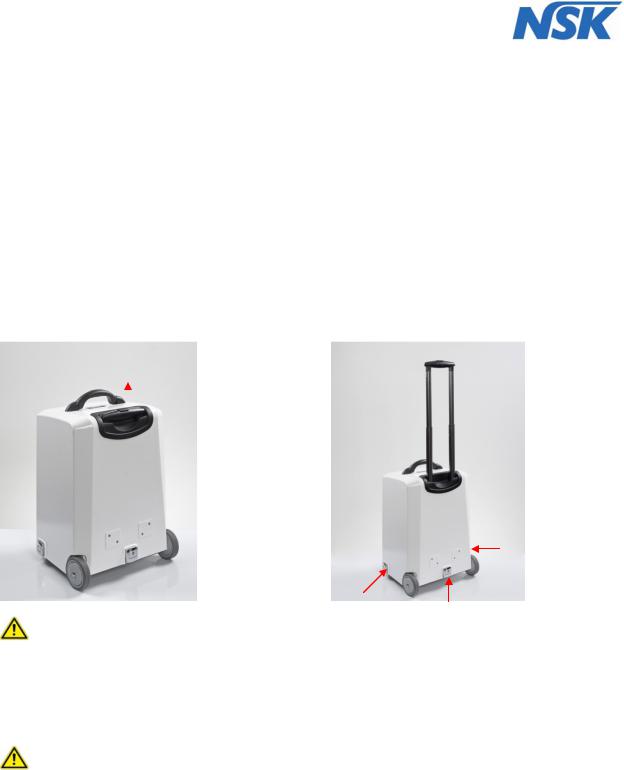
First, the outer packaging (box) must be removed by lifting the device from the box using the handle attached to the middle of the cover. We recommend that you keep the packaging.
Afterward the telescopic handle can be pulled out and the device can be rolled to the location where it will be used.
(fig. 1).
There the cover can be removed after opening the three clips (see fig. 2)
fig.1 Unlocking the trolley handle |
fig.2 Opening the cover |
Check that the device has been set up on a flat and stable surface! If this is not the case, change the location.
The ventilation slits in the housing MUST NOT be adjusted or covered. Sufficient ventilation of the device is required to avoid that overheating of internal components occurs.
 Attention! Wait before switching-on and using the DENTALONE, until it has adapted to the ambient temperature (E.g. after a cold night in the car). Note the admissible operation conditions (see section 5).
Attention: in order to avoid the risk of an electric shock this device may only be connected to a supply network with protective earth.
The device has to be installed in such a way that in case of failure a separation from the supply network is easily possible by pulling the power plug.
Use only the supplied power cord.
Page 13 of 54

8.Use
8.1Description of components
The DENTALONE consists of a base (10) and height-adjustable console (4), which can be pulled out upwards at two columns (5) and locked.
On the left side of the DENTALONE are the power inlet with the power switch, the fuse holder (1) (fig.3), and the connector socket for the foot switch (2).
1
2
3
fig.3 |
fig.4 |
At the rear of the housing a removable water tank (8) with a capacity of 500 ml is located. (see fig.5).
4
5
6
7
8
9 
10
11
fig.5 |
fig.6 |
Page 14 of 54

At the front is placed a removable waste water container (12) for suction waste (fig.6).
3
|
|
12 |
|
|
|
|
|
|
|
|
|
|
|
|
|
|
|
|
|
|
|
|
13 |
|
|
|
|
|
|
|
|
|
|
|
|
|
|
|
|
|
|
|
|
|
|
|
|
|
|
|
|
|
15 |
|
|
|
|
|
14 |
|
|
|
|
|
|
|
|
|
|
|
|
|
|
|
|
|
|
|
|
|
|
|
|
|
|
|
|
|
|
fig.7 |
|
|
fig.8 |
|
|
|
|
|
|
|
|
||||||
1. |
Power switch / power inlet / safety switch |
|
|
|
|
|
|
|
|
|
|
|
|
|
|||
2. |
Foot pedal connection |
16 |
|
|
|
|
|
|
|
|
|
|
|
||||
3. |
Foot pedal |
|
|
|
|
|
|
|
|
|
|
|
|||||
|
|
|
|
|
|
|
|
|
|
|
|
|
|||||
4. |
Console |
|
|
|
|
|
|
|
|
|
|
|
|
|
|||
5. |
Pillar guide |
17 |
|
|
|
|
|
|
|
|
|
|
17 |
||||
6. |
Housing |
|
|
|
|
|
|
|
|
|
|
|
|
|
|||
7. |
Compressed air filter |
|
|
|
|
|
|
|
|
|
|
|
|
|
|||
8. |
Water tank |
|
|
|
|
|
|
|
|
|
|
|
|
|
|||
9. |
Power cord |
|
|
|
|
|
|
|
|
|
|
|
|
|
|||
10. |
Base |
|
|
|
|
|
|
|
|
|
|
|
|
|
|||
11. |
Foot stand with handle |
|
|
|
|
|
|
|
|
|
|
|
|
|
|||
12. |
Waste water container |
|
|
|
|
|
|
|
|
|
|
|
|
|
|||
13. |
Spray-adjuster for Scaler |
|
|
|
|
|
|
|
|
|
|
|
|
|
|||
14. |
Spray-adjuster for Motor |
|
|
|
|
|
|
|
|
|
|
|
|
|
|||
15. |
Spray ON/OFF Switch |
|
|
|
|
|
|
|
|
|
|
|
|
|
|||
16. |
Moulded foam insert |
|
|
|
|
|
|
|
|
|
|
|
|
|
|||
17. |
2 x electrical unlocking switches for console |
|
|
|
|
|
|
|
|
|
|
|
|
|
|||
18. |
Instrument holder |
|
|
|
|
|
|
|
|
|
|
|
|
|
|||
19. |
Ultrasonic Scaler |
|
|
|
|
|
|
|
|
|
|
|
|
|
|||
20. |
Micro-motor |
|
|
|
|
|
|
|
|
|
|
|
|
|
|||
|
|
|
|
|
19 |
|
20 |
|
|
|
|
|
|||||
|
|
18 |
|
|
|
|
21 |
|
22 |
23 |
|||||||
21. |
Multifunction control panel |
|
|
|
|
|
|
|
|||||||||
|
|
|
|
|
|
|
|
|
|
|
|||||||
22. |
Multifunction syringe |
|
|
Abb. |
|
|
|
|
|
|
|
|
|
||||
|
|
|
|
|
|
|
|
|
|
|
|||||||
|
|
9 |
|
|
|
|
|
|
|
|
|||||||
23.Saliva ejector
8.2Preparation / initial operation
First of all the DENTALONE has to be connected to a suitable power supply using the power cord provided (9) at the power inlet (1).
Please correspondingly consider the regulations for medically used rooms in accordance with DIN VDE 0107.
The instrument tubings and suction hoses have to be taken from the lower storage space and to be structured in such a way that the loops are not entwined with each other.
Now the power switch (1) at the left side of the device can be switched on. The indicator lamp shows a green light.
If the DENTALONE is used for the first time or after a long period out of operation, the internal compressor is working initially until the operating pressure is reached. This process can take up to 20 seconds.
At this stage the console has to be brought into the working position. The procedure is as follows: In the recessed grips at the left and right side of the console there are unlocking switches (17) and through the activation of the rocker switches (Fig.10) the console (4) can be electrically unlocked. (works only when the DENTALONE is turned on and the device has power)
Page 15 of 54

By activating the rocker switches (see illustration (fig.10) and pulling at the recessed grips on both sides the operating console (4) can manually be moved upwards until it is audibly locked in the working position, as soon.
After pressing both locking switches (17) and unlocking the console (4) (audible click), the console has to be lifted within 1.5 seconds to raise it from the lower position into the upper position. Otherwise, the lock function is activated automatically again. In this case both locking switch (17) must be released again and process must be repeated. The same applies to lowering the console.
You should remove the moulded foam part (16), which is placed on the console (4) for protecting and safeguarding the instruments and store it for future transports.
Please check after transport whether the instruments are still placed properly and in the correct order in the instrument holder (18) (from left to right: Scaler (19); Micro-motor (20); Multifunction syringe (22); Saliva ejector (23)). Refer to fig.9.
Then swivel the instrument holder (18) by gently pulling on the control panel (21) in a comfortable working position until it is audibly locked. (fig.10).
There are 2 additional stop positions which facilitate an individual positioning, so that the instruments can comfortably be taken out and the display i of the control panel (21) can be easily seen (fig.11).
fig.10 |
fig.11 |
 Please check whether all instruments are completely assembled.
Check your device for completeness in accordance with the delivery notes.
The footswitch (3) is located in a holder mounted side on in the lower part of the device. (fig.7).
Remove the foot switch from its holder and connect it to foot switch socket (2) at the left side of the device (fig.3 and fig.4).
Before every operation check the device for proper condition.
This concerns the stability of the unit, the two-sided lock in the extended position of the console as well as the measures described in the following sections of these instructions. All cables, tubings and the suctino hose should be checked for any damage.
Furthermore , the instrument detection and function of the instruments and also the default settings on the control panel should be checked. (see section 8.5 and annex A (control panel))
Before the initial operation always check whether there is enough clean water in the water tank and the suction container (12) is empty.
8.3Filling the water tank
 Before removing of the water tank (8) the DENTALONE has to be switched off at the main switch (1) or the spray switch (15) has to switch off. Following that any remaining pressure in the system has to be drained by pressing the venting valve (see fig.12). After that the fresh water tank can be pulled off the coupling pins by releasing the coupling.
(See fig.13).
Page 16 of 54

fig.12 |
fig.13 |
After unscrewing the screw cap from the bottle any remaining water should be disposed and the container has to be thoroughly cleaned according in accordance with applicable guidelines.
The water tank (8) should to be disinfected before refilling in accordance with applicable guidelines. (Refer to section 9.5)
Only use drinking water quality water suitable for dental equipment must be used. The maximum capacity of the tank is 500 ml
Before closing the bottle also the screw cover has to be cleaned, disinfected and checked for correct seating of the lid gasket. Please screw the cap hand-tight. Do not overtighten!
Now the water tank can be attached again to the quick release fitting and the Spray switch (15) can be switched back on.
 The compressor will start again to establish the operating pressure
8.4Completion and arrangement of instruments
During transport of the device all sterile parts of instruments, i.e. Scaler and Scaler Tips, motor handpiece; the tips of the syringe and the saliva ejector have to be packed separately and must be fitted again by the user.
See the detailed instructions in section 8.6.and annex B (Scaler) and annex C (Motor).
The instrument holders, as already described in section 8.2, have been located with functionality and ergonomic operation in mind
 The instruments may not swapped between holders, because this would cause malfunctions!
 Each day before the first treatment each instrument should be activated 30 seconds in order to rinse stagnant water in instrument hoses.
Initial operation and practice interruption of more than 24 hours
Before the initial operation and before and after each treatment pause (> 10 hours), disinfection, cleaning, sterilization has to be carried out! (See section 9.)
Then fill the water tank (8) with fresh drinking water.
Start rinsing process: by switching on the spray function two times in succession for approximately 20 seconds all lines are rinsed with water.
The spray regulators (13) and (14) have to be adjusted to maximum flow setting.
By doing so any disinfection agents in the instrument hoses are thoroughly removed from the hoses.
 For safety reasons the device is to be switched off at the power switch (1) before leaving the surgery.
Page 17 of 54
 Loading...