

NSC LM2601MTCX, LM2601MTC, LM2601MTCEVAL Datasheet
LM2601
Adapter Interface Circuit
General Description
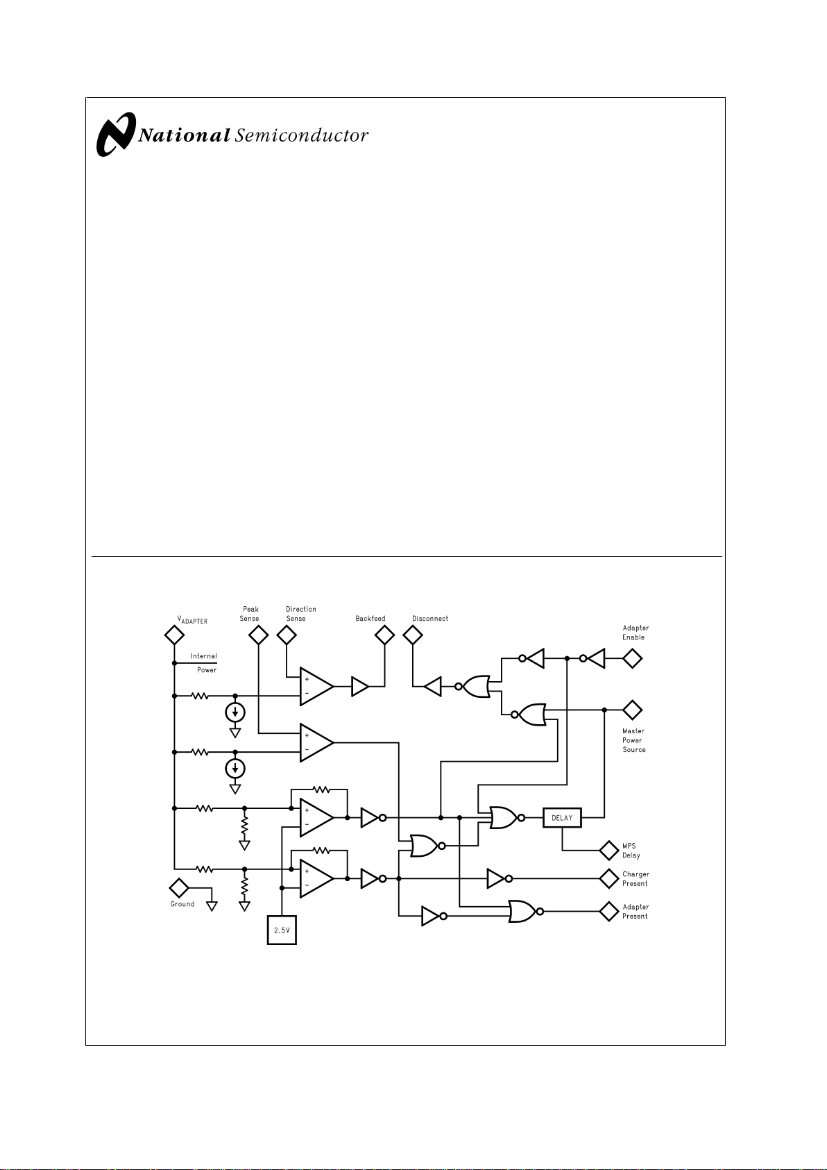
The Adapter Interface Circuit (AIC) is used to sense the
presence of an external power source for a portable computer. It notifies the computer if a source is present and
indicates if the source is appropriate for charging battery
packs inside the computer. The AIC also senses an adapter
current and itsdirection.AIC isolates theadapter and signals
the computer when peak current threshold is exceeded.
LM2601 drives P-channel FETs. No high current rated
Schottky diode is required to implement an adapter switchover circuit. This significantly decreases additional heat dissipation during simultaneous fast battery charging while running a computer, particularly in Maximum Performance
mode of operation
Features
n Detects an AC-DC adapter suitable for battery charging
or an airplane or car power line adapter that should not
be used for battery charging
n Allows the implementation of intelligent switchover
circuits for portable systems
n LM2601 shuts down automatically when adapter is
removed
n Low leakage current from battery when not powered
n Drives P-channel FETs, no Schottky diodes are required
n No reverse inrush current from battery into the adapter
output capacitance
n Allows for battery capacity gas-gauge calibration under
system software/firmware control
n Adapter over current threshold programmable with
external resistors
n Wide input range: 5V - 24V
n Available in TSSOP-14 package
Applications
n Portable Computers
n Portable IAs (Internet Appliances, Information
Appliances)
n Other Battery Powered Devices
Block Diagram
10130901
April 2001
LM2601 Adapter Interface Circuit
© 2001 National Semiconductor Corporation DS101309 www.national.com
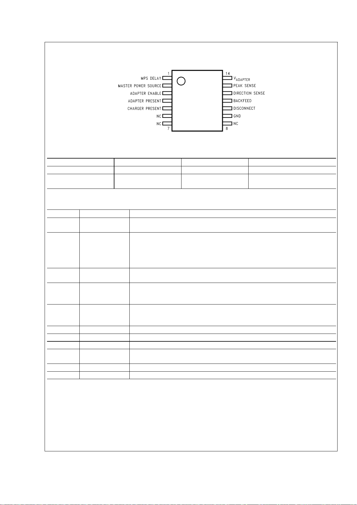
Pin Configuration
TSSOP-14
10130902
Ordering Information
Order Number Package Number Package Type Supplied As
*
LM2601MTC MTC14 TSSOP-14 Rail (94 Units/Rail)
LM2601MTCX MTC14 TSSOP-14 Tape and Reel (2500
Units/Reel)
*
Partial Rails are available, there is no minimum order quantity. Tape and Reel is supplied as full reels only.
Pin Description
Pin No. Name Function
1 MPS DELAY A capacitor between this pin and ground sets the delay of the MPS risetime. See MPS
DELAY description in Typical Application section.
2 MASTER POWER
SOURCE
Bi-directional logic pin. If driven high by an external source, indicates that a battery is
powering the power bus. If driven high by the AIC, indicates the adapter is powering the
bus. AIC cannot drive MPS low. If there is no valid adapter voltage present, the pin is not
an output but a high impedance logic input. The input is pulled-down via an internal 40k
resistor.
3 ADAPTER
ENABLE
Logic input pin. Active high. Grants permission to the adapter to drive both the power bus
and the MPS signal.
4 ADAPTER
PRESENT
Logic output pin. High when 12 volts
<
V
ADAPTER
<
17 volts. The output typically has 40k
pull-down resistor. The source current is not internally limited and the part can be
damaged if the output is shorted to ground when driven HIGH.
5 CHARGER
PRESENT
Logic output pin. High when V
ADAPTER
>
17 volts. The output typically has 40k pull-down
resistor. The source current is not internally limited and the part can be damaged if the
output is shorted to ground when driven HIGH.
9 GND IC ground pin.
10 DISCONNECT Drives the gate of the disconnect P-ch FET.
11 BACKFEED Drives the gate of the backfeed P-ch FET.
12 DIRECTION
SENSE
Connection for current sense resistor to control BACKFEED.
13 PEAK SENSE Connection for current sense resistor to control DISCONNECT.
14 V
ADAPTER
Power input pin. Output of AC adapter, auto adapter or airline adapter.
LM2601
www.national.com 2
 Loading...