

NSC DP83936AVUL-25 Datasheet
TL/F/12597
DP83936AVUL-20/25/33 MHz Full Duplex SONIC-T Systems-Oriented
Network Interface Controller with Twisted Pair Interface
January 1996
DP83936AVUL-20/25/33 MHz Full Duplex SONICTM-T
Systems-Oriented Network Interface Controller
with Twisted Pair Interface
General Description
The SONIC-T (Systems-Oriented Network Interface Controller with Twisted Pair) is a second-generation Ethernet Controller designed to meet the demands of today’s high-speed
32- and 16-bit systems. Its system interface operates with a
high speed DMA that typically consumes less than 5% of
the bus bandwidth. Selectable bus modes provide both big
and little endian byte ordering and a clean interface to standard microprocessors. The linked-list buffer management
system of SONIC-T offers maximum flexibility in a variety of
environments from PC-oriented adapters to high-speed
motherboard designs. The SONIC-T can be configured for
full duplex operation. Furthermore, the SONIC-T integrates
a fully-compatible IEEE 802.3 Encoder/Decoder (ENDEC)
and a Twisted Pair Interface which provide a one-chip solution for Ethernet when using 10BASE-T. When using
10BASE2 or 10BASE5, the SONIC-T may be paired with the
DP8392 Coaxial Transceiver Interface to achieve a simple
2-chip solution.
For increased performance, the SONIC-T implements a
unique buffer management scheme to efficiently process
receive and transmit packets in system memory. No intermediate packet copy is necessary. The receive buffer management uses three areas in memory for (1) allocating additional resources, (2) indicating status information, and (3)
buffering packet data. During reception, the SONIC-T stores
packets in the buffer area, then indicates receive status and
control information in the descriptor area. The system allocates more memory resources to the SONIC-T by adding
descriptors to the memory resource area. The transmit buffer management uses two areas in memory:
1. indicating status and control information;
2. fetching packet data.
The system can create a transmit queue allowing multiple
packets to be transmitted from a single transmit command.
The packet data can reside on any arbitrary byte boundary
and can exist in several non-contiguous locations.
Features
Y
32-bit non-multiplexed address and data bus
Y
Configurable for Full Duplex operation
Y
Auto AUI/TPI selection
Y
High-speed interruptible DMA
Y
Linked-list buffer management maximizes flexibility
Y
Two independent 32-byte transmit and receive FIFOs
Y
Bus compatibility for all standard microprocessors
Y
Supports big and little endian formats
Y
Integrated IEEE 802.3 ENDEC
Y
Integrated Twisted Pair Interface
Y
Complete address filtering for up to 16 physical and/or
multicast addresses
Y
32-bit general-purpose timer
Y
Loopback diagnostics
Y
Fabricated in low-power CMOS
Y
160 PQFP package
Y
Full network management facilities support the 802.3
layer management standard
Y
Integrated support for bridge and repeater applications
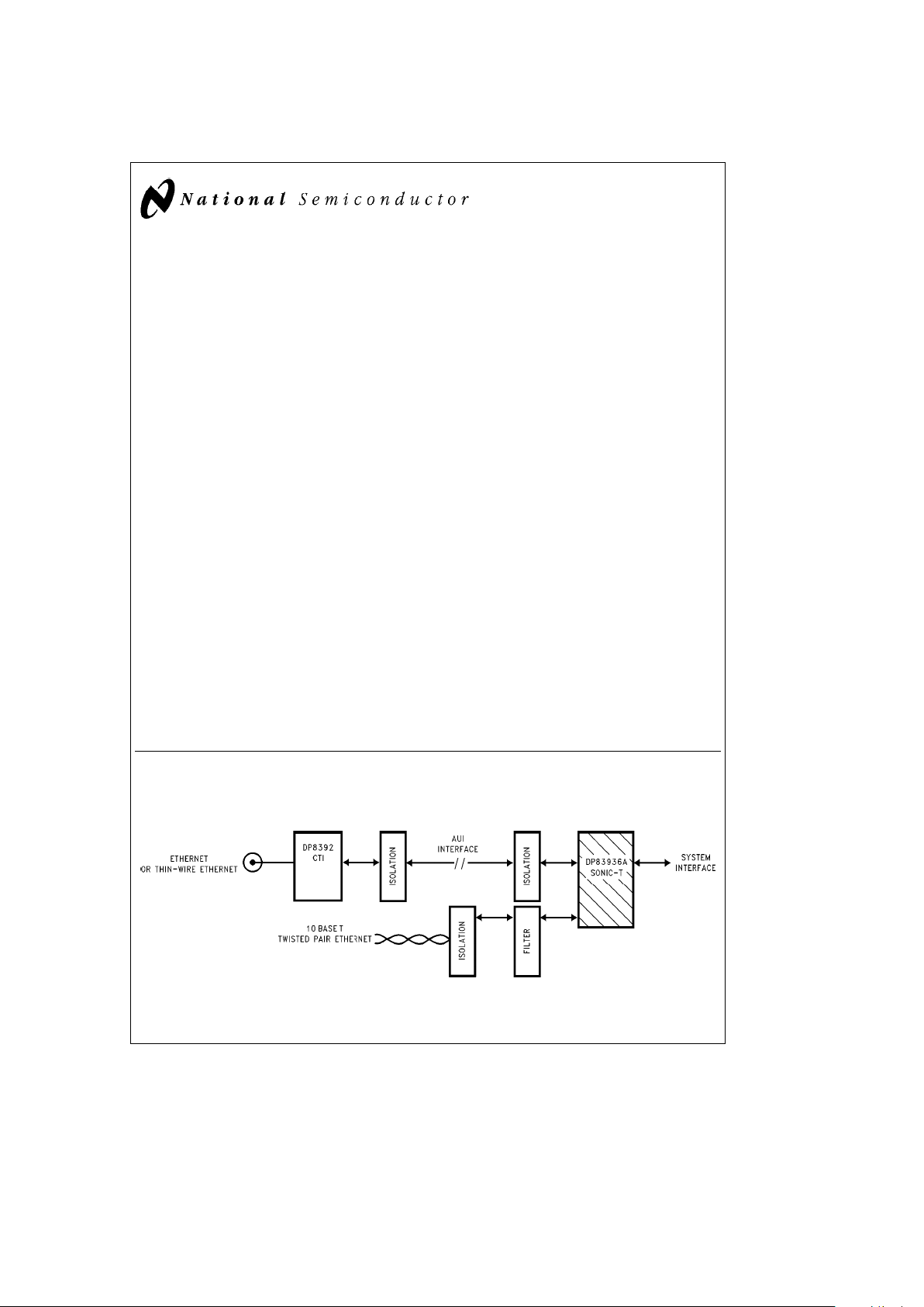
System Diagram
IEEE 802.3 Ethernet/Thin-Ethernet/10BaseT Station
TL/F/12597– 1
TRI-STATEÉis a registered trademark of National Semiconductor Corporation.
SONIC
TM
is a trademark of National Semiconductor Corporation.
C
1996 National Semiconductor Corporation RRD-B30M36/Printed in U. S. A.
http://www.national.com

Table of Contents
1.0 CONNECTION DIAGRAMS
1.1 Pin Connection Diagram, National/Intel Mode
1.2 Pin Connection Diagram, Motorola Mode
2.0 PIN DESCRIPTION
3.0 FUNCTIONAL DESCRIPTION
3.1 Twisted Pair Interface Module
3.2 IEEE 802.3 Encoder/Decoder (ENDEC) Unit
3.2.1 ENDEC Operation
3.2.2 Selecting an External ENDEC
3.3 Media Access Control (MAC) Unit
3.3.1 MAC Receive Section
3.3.2 MAC Transmit Section
3.3.3 Full Duplex Operation
3.4 Data Width and Byte Ordering
3.5 FIFO and Control Logic
3.5.1 Receive FIFO
3.5.2 Transmit FIFO
3.6 Status and Configuration Registers
3.7 Bus Interface
3.8 Loopback and Diagnostics
3.8.1 Loopback Procedure
3.9 Network Management Functions
4.0 TRANSMIT/RECEIVE IEEE 802.3 FRAME FORMAT
4.1 Preamble and Start of Frame Delimiter (SFD)
4.2 Destination Address
4.3 Source Address
4.4 Length/Type Field
4.5 Data Field
4.6 FCS Field
4.7 MAC (Media Access Control) Conformance
5.0 BUFFER MANAGEMENT
5.1 Buffer Management Overview
5.2 Descriptor Areas
5.2.1 Naming Convention for Descriptors
5.2.2 Abbreviations
5.2.3 Buffer Management Base Addresses
5.3 Descriptor Data Alignment
5.4 Receive Buffer Management
5.4.1 Receive Resource Area (RRA)
5.4.2 Receive Buffer Area (RBA)
5.4.3 Receive Descriptor Area (RDA)
5.4.4 Receive Buffer Management Initialization
5.4.5 Beginning of Reception
5.4.6 End of Packet Processing
5.4.7 Overflow Conditions
5.5 Transmit Buffer Management
5.5.1 Transmit Descriptor Area (TDA)
5.5.2 Transmit Buffer Area (TBA)
5.5.3 Preparing to Transmit
5.5.4 Dynamically Adding TDA Descriptors
6.0 SONIC-T REGISTERS
6.1 The CAM Unit
6.1.1 The Load CAM Command
6.2 Full Duplex Operation
6.3 Status/Control Registers
6.4 Register Description
6.4.1 Command Register
6.4.2 Data Configuration Register
6.4.3 Receive Control Register
6.4.4 Transmit Control Register
6.4.5 Interrupt Mask Register
6.4.6 Interrupt Status Register
6.4.7 Data Configuration Register 2
6.4.8 Transmit Registers
6.4.9 Receive Registers
6.4.10 CAM Registers
6.4.11 Tally Counters
6.4.12 General Purpose Timer
6.4.13 Silicon Revision Register
7.0 BUS INTERFACE
7.1 Pin Configurations
7.2 System Configuration
7.3 Bus Operations
7.3.1 Acquiring the Bus
7.3.2 Block Transfers
7.3.3 Bus Status
7.3.4 Bus Mode Compatibility
7.3.5 Master Mode Bus Cycles
7.3.6 Bus Exceptions (Bus Retry)
7.3.7 Slave Mode Bus Cycle
7.3.8 On-Chip Memory Arbiter
7.3.9 Chip Reset
8.0 NETWORK INTERFACING
8.1 Manchester Encoder and Differential Driver
8.1.1 Manchester Decoder
8.1.2 Collision Translator
8.1.3 Oscillator Inputs
8.1.4 Power Supply Considerations
8.2 Twisted Pair Interface Module
9.0 AC AND DC SPECIFICATIONS
10.0 AC TIMING TEST CONDITIONS
http://www.national.com 2
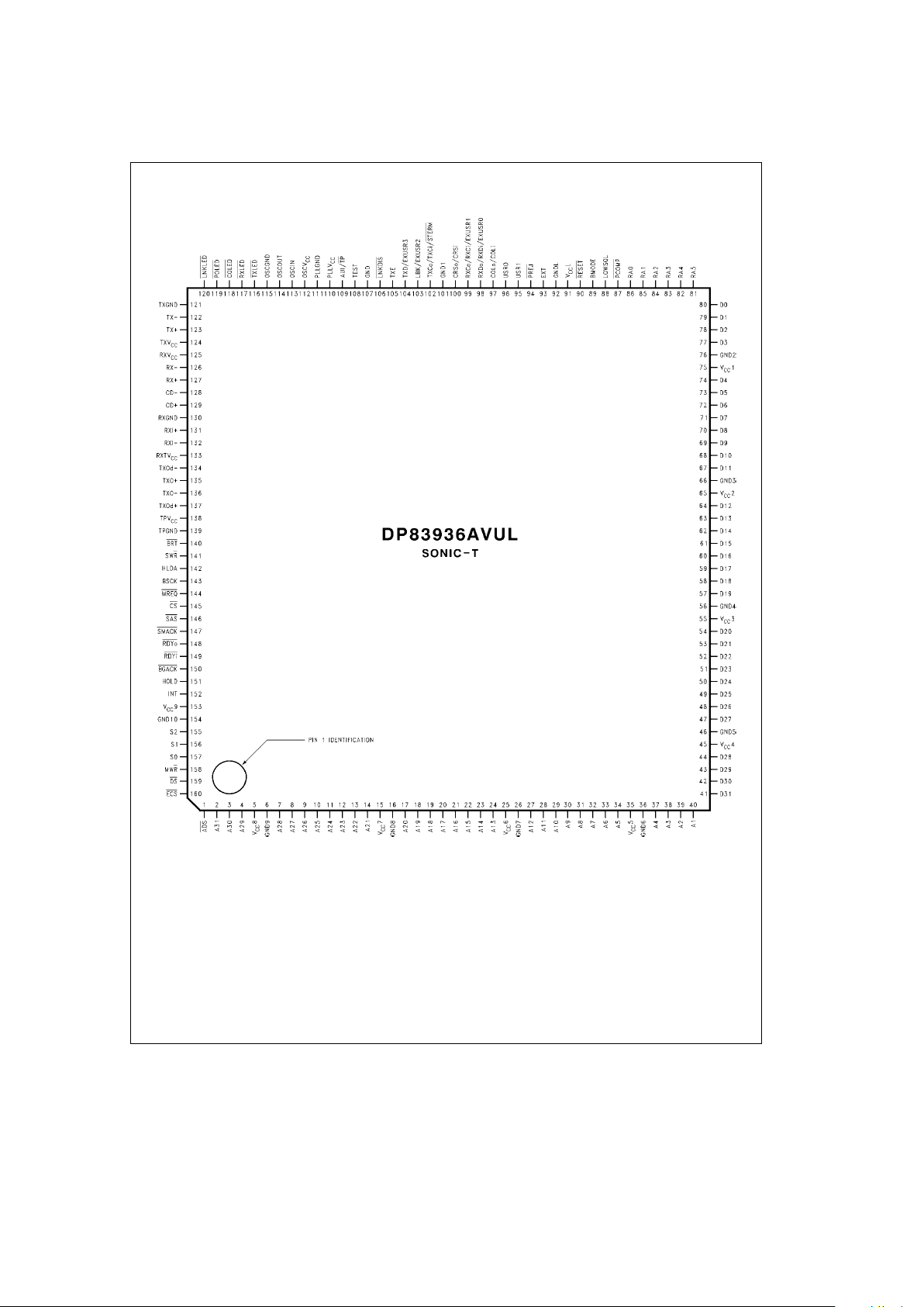
1.0 Connection Diagrams
1.1 PIN CONNECTION DIAGRAM, NATIONAL/INTEL MODE
TL/F/12597– 2
http://www.national.com3
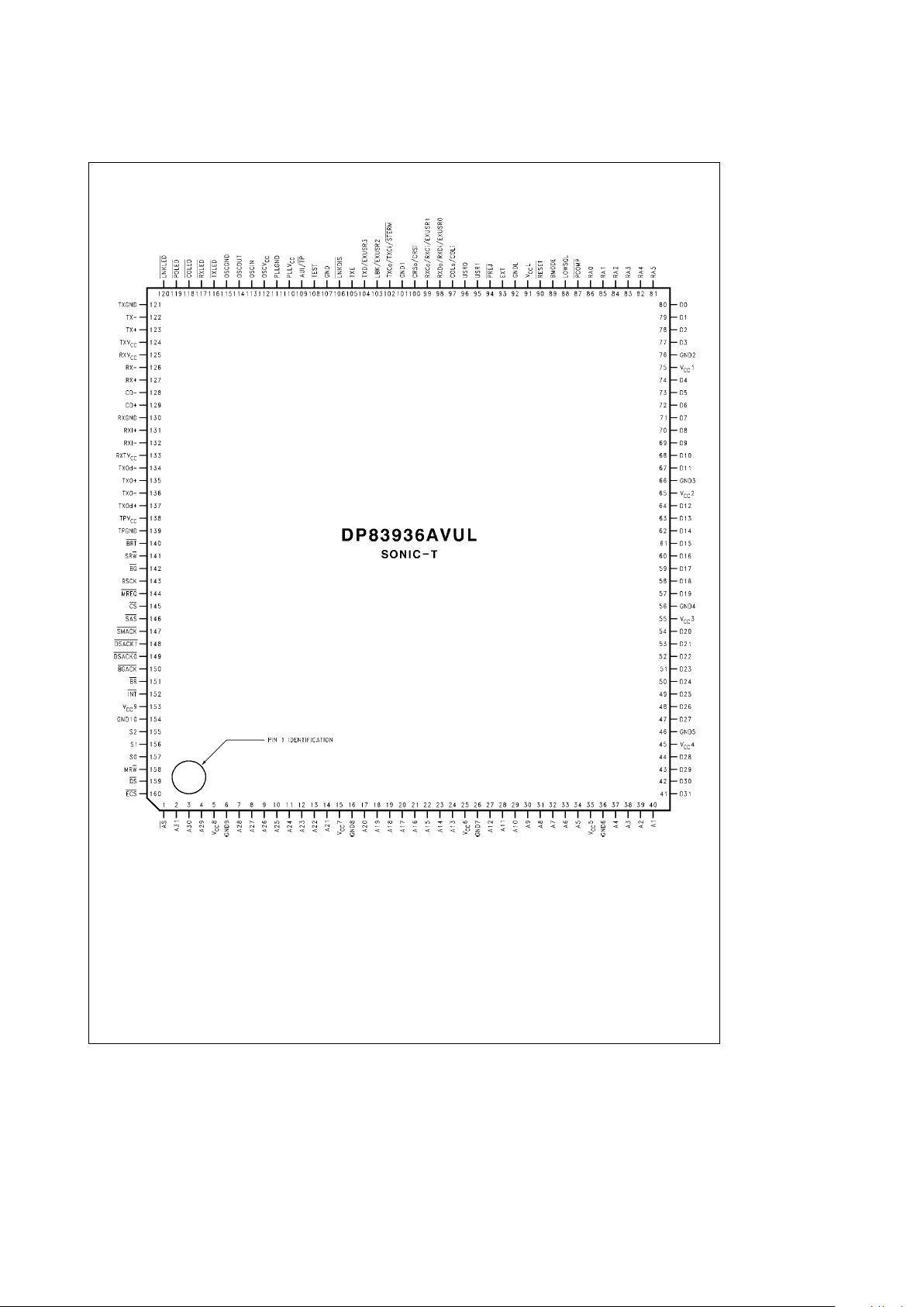
1.0 Connection Diagrams (Continued)
1.2 PIN CONNECTION DIAGRAM, MOTOROLA MODE
TL/F/12597– 3
http://www.national.com 4
2.0 Pin Description
I
e
Input
OeOutput
ZeTRI-STATEÉInput, TTL compatible
ECLeEmitter Coupled Logic type drivers for interfacing to
the Attachment Unit Interface.
TP
e
Totem Pole type drivers. These drivers are driven
either high or low and are always driven. Drive levels are CMOS compatible.
TRI
e
TRI-STATE drivers. These pins are driven high, low
or TRI-STATE. Drive levels are CMOS compatible.
These pins may also be inputs (depending on the
pin).
OC
e
Open Collector type drivers. These drivers are
TRI-STATE when inactive and are driven low when
active. These pins may also be inputs (depending
on the pin).
TPI
e
Twisted Pair Interface.
Pin names which contain a ‘‘/’’ indicate dual function pins.
TABLE 2-1. Pin Description
Symbol
Driver
Direction Description
Type
NETWORK INTERFACE PINS
EXT I EXTERNAL ENDEC SELECT: Tying this pin to VCC(EXTe1) disables the internal
ENDEC and allows an external ENDEC to be used. Tying this pin to ground (EXT
e
0)
enables the internal ENDEC. This pin must be tied either to V
CC
or ground. Note the
alternate pin definitions for CRSo/CRSi, COLo/COLi, RXDo/RXDi, RXCo/RXCi, and
TXCo/TXCi. When EXT
e
0 the first pin definition is used and when EXTe1 the second
pin definition is used.
AUI/TP I ATTACHMENT UNIT INTERFACE (AUI)/TWISTED PAIR (TP) SELECT: Tying this pin
to VCC(AUI/TPe1) enables the AUI mode for interface with the ENDEC unit. Tying this
pin to GND (AUI/TP
e
0) enables the TPI Module mode for interface with the ENDEC
unit.
TXOda, TXOa, TPI O TWISTED PAIR TRANSMIT OUTPUTS: These high drive CMOS level outputs are
resistively combined external to the chip to produce a differential output signal with
TXO
b
, TXOd
b
equalization to compensate for Intersymbol Interference (ISI) on the twisted pair medium.
RXIa, RXI
b
TPI I TWISTED PAIR RECEIVE INPUTS: These inputs feed a differential amplifier which
passes valid data to the ENDEC module.
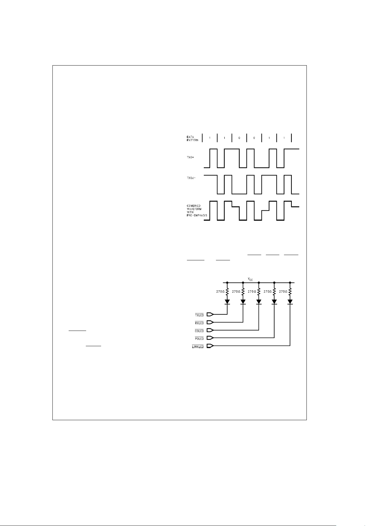
TXLED TP O TRANSMIT: An active low output. It is asserted for approximately 50 ms whenever the
SONIC-T Controller transmits data in either AUI or TPI modes.
RXLED TP O RECEIVE: An active low output. It is asserted for approximately 50 ms whenever receive
data is detected in either AUI or TPI mode.
COLED TP O COLLISION: An active low output. It is asserted for approximately 50 ms whenever the
SONIC-T Controller detects a collision in either AUI or TPI modes.
POLED TP O POLARITY: An active low output. This signal is normally inactive. When the TPI module
detects seven consecutive link pulses or three consecutive received packets with
reversed polarity, it is asserted.
LINKLED TP O GOOD LINK: An active low output. This pin operates as an output to display link integrity
status if this function has not been disabled by the LNKDIS pin described below. This
output is off if the SONIC-T Controller is in AUI mode or if link testing is enabled and the
link integrity is bad (i.e., the twisted pair link has been broken).
This output is on if the SONIC-T Controller is in Twisted Pair Interface (TPI) mode, link
integrity checking is enabled and the link integrity is good (i.e., the twisted pair link has
not been broken) or if the link testing is disabled.
LNKDIS I LINK DISABLE: When this pin is tied to GND (LNKDISe0), the link test pulse
generation and integrity checking function are both disabled.
LOWSQL I LOW SQUELCH SELECT: Tying this pin to VCC(LOWSQLe1) sets the squelch mode
to use a squelch threshold level lower than that of the 10BASE-T specification (see
Section 3.1).
http://www.national.com5

2.0 Pin Description (Continued)
TABLE 2-1. Pin Description (Continued)
Symbol
Driver
Direction Description
Type
NETWORK INTERFACE PINS (Continued)
CD
a
I AUI COLLISIONa: The positive differential collision input from the transceiver. This pin should
be unconnected when an external ENDEC is selected (EXT
e
1).
CD
b
I AUI COLLISIONb: The negative differential collision input from the transceiver. This pin should
be unconnected when an external ENDEC is selected (EXT
e
1).
RX
a
I AUI RECEIVEa: The positive differential receive data input from the transceiver. This pin should
be unconnected when an external ENDEC is selected (EXT
e
1).
RX
b
I AUI RECEIVEb: The negative differential receive data input from the transceiver. This pin
should be unconnected when an external ENDEC is selected (EXT
e
1).
TX
a
ECL O AUI TRANSMITa: The positive differential transmit output to the transceiver. This pin should be
unconnected when an external ENDEC is selected (EXT
e
1).
TX
b
ECL O AUI TRANSMITb: The negative differential transmit output to the transceiver. This pin should
be unconnected when an external ENDEC is selected (EXT
e
1).
CRSo/ TP O CARRIER SENSE OUTPUT (CRSo) from the internal ENDEC (EXTe0): When EXTe0 the
CRSo signal is internally connected between the ENDEC and MAC units. It is asserted on the first
CRSi I
valid high-to-low transition in the receive data (RX
g
). This signal remains active 1.5 bit times
after the last bit of data. Although this signal is used internally by the SONIC-T, it is also provided
as an output to the user.
CARRIER SENSE INPUT (CRSi) from an external ENDEC (EXT
e
1): The CRSi signal is
activated high when the external ENDEC detects valid data at its receive inputs.
COLo/ TP O COLLISION OUTPUT (COLo) from the internal ENDEC (EXTe0): When EXTe0 the COLo
signal is internally connected between the ENDEC and MAC units. This signal generates an
COLi I
active high signal when the 10 MHz collision signal from the transceiver is detected. Although this
signal is used internally by the SONIC-T, it is also provided as an output to the user.
COLLISION DETECT INPUT (COLi) from an external ENDEC (EXT
e
1): The COLi signal is
activated from an external ENDEC when a collision is detected. This pin is monitored during
transmissions from the beginning of the Start of Frame Delimiter (SFD) to the end of the packet.
At the end of transmission, this signal is monitored by the SONIC-T for CD heartbeat.
RXDo/ TP O This pin will be TRI-STATE until the DCR has been written to. (See Section 6.4.2,
RXDi/ I EXBUS, for more information.)
EXUSR0 TRI O, Z RECEIVE DATA OUTPUT (RXDo) from the internal ENDEC (EXT
e
0): NRZ data output. When
EXT
e
0 the RXDo signal is internally connected between the ENDEC and MAC units. This
signal must be sampled on the rising edge of the receive clock output (RXCo). Although this
signal is used internally by the SONIC-T, it is also provided as an output to the user.
RECEIVE DATA INPUT (RXDi) from an external ENDEC (EXT
e
1): The NRZ data decoded
from the external ENDEC. This data is clocked in on the rising edge of RXCi.
EXTENDED USER OUTPUT (EXUSR0): When EXBUS has been set (see Section 6.4.2), this pin
becomes a programmable output. It will remain TRI-STATE until the SONIC-T becomes a bus
master, at which time it will be driven according to the value programmed in the DCR2 (see
Section 6.4.7).
RXCo/ TP O This pin will be TRI-STATE until the DCR has been written to. (See Section 6.4.2,
RXCi/ I EXBUS, for more information.)
EXUSR1 TRI O, Z RECEIVE CLOCK OUTPUT (RXCo) from the internal ENDEC (EXT
e
0): When EXTe0 the
RXCo signal is internally connected between the ENDEC and MAC units. This signal is the
receive clock that is derived from the Manchester data stream. It remains active 5-bit times after
the deassertion of CRSo. Although this signal is used internally by the SONIC-T it is also provided
as an output to the user.
RECEIVE CLOCK INPUT (RXCi) from an external ENDEC (EXT
e
1): The receive clock that is
derived from the Manchester data stream. This signal is generated from an external ENDEC.
EXTENDED USER OUTPUT (EXUSR1): When EXBUS has been set (see Section 6.4.2), this pin
becomes a programmable output. It will remain TRI-STATE until the SONIC-T becomes a bus
master, at which time it will be driven according to the value programmed in the DCR2 (see
Section 6.4.7).
http://www.national.com 6
2.0 Pin Description (Continued)
TABLE 2-1. Pin Description (Continued)
Symbol
Driver
Direction Description
Type
NETWORK INTERFACE PINS (Continued)
TXD/ TP O This pin will be TRI-STATE until the DCR has been written to. (See Section 6.4.2, EXBUS, for
more information.)
EXUSR3 TRI O, Z
TRANSMIT DATA (TXD): The serial NRZ data from the MAC unit which is to be decoded by an
external ENDEC. Data is valid on the rising edge of TXC. Although this signal is used internally by
the SONIC-T it is also provided as an output to the user.
EXTENDED USER OUTPUT (EXUSR3): When EXBUS has been set (see Section 6.4.2), this pin
becomes a programmable output. It will remain TRI-STATE until the SONIC-T becomes a bus
master, at which time it will be driven according to the value programmed in the DCR2 (see
Section 6.4.7).
TXE TP O TRANSMIT ENABLE: This pin is driven high when the SONIC-T begins transmission and remains
active until the last byte is transmitted. Although this signal is used internally by the SONIC-T it is
also provided as an output to the user.
TXCo/ TRI O, Z This pin will be TRI-STATE until the DCR has been written to. (See Section 6.4.2,
TXCi/ I EXBUS, for more information.)
STERM
I TRANSMIT CLOCK OUTPUT (TXCo) from the internal ENDEC (EXTe0): This 10 MHz transmit
clock output is derived from the 20 MHz oscillator input. When EXTe0 the TXCo signal is
internally connected between the ENDEC and MAC units. Although this signal is used internally
by the SONIC-T, it is also provided as an output to the user.
TRANSMIT CLOCK INPUT (TXCi) from an external ENDEC (EXT
e
1): This input clock from an
external ENDEC is used for shifting data out of the MAC unit serializer. This clock is nominally
10 MHz.
SYNCHRONOUS TERMINATION (STERM
): When the SONIC-T is a bus master, it samples this
pin before terminating its memory cycle. This pin is sampled synchronously and may only be used
in asynchronous bus mode when BMODEe1. (See Section 7.3.5 for more details.)
LBK/ TP O This pin will be TRI-STATE until the DCR has been written to. (See Section 6.4.2, EXBUS, for
more information.)
EXUSR2 TRI O, Z
LOOPBACK (LBK): When ENDEC Loopback mode is enabled, LBK is asserted high. Although
this signal is used internally by the SONIC-T it is also provided as an output to the user.
EXTENDED USER OUTPUT (EXUSR2): When EXBUS has been set (see Section 6.4.2), this pin
becomes a programmable output. It will remain TRI-STATE until the SONIC-T becomes a bus
master, at which time it will be driven according to the value programmed in the DCR2 (see
Section 6.4.7).
PCOMP TRI O, Z PACKET COMPRESSION: This pin is used with the Management Bus of the DP83950, Repeater
Interface Controller (RIC). The SONIC-T can be programmed to assert PCOMP
whenever there is
a CAM match, or when there is not a match. The RIC uses this signal to compress (shorten) a
received packet for management purposes and to reduce memory usage. (See the DP83950
datasheet for more details on the RIC Management Bus.) The operation of this pin is controlled
by bits 1 and 2 in the DCR2 register. PCOMP
will remain TRI-STATE until these bits are written to.
This signal is asserted right after the 4th bit of the 7th byte of the incoming packet and is
deasserted one transmit clock (TXC) after CSR is driven low.
PREJ I PACKET REJECT: This signal is used to reject received packets. When asserted low for at least
two receive clock cycles (RXC), the SONIC-T will reject the incoming packet. This pin can be
asserted up to the 2nd to the last bit of reception to reject a packet.
http://www.national.com7
2.0 Pin Description (Continued)
TABLE 2-1. Pin Description (Continued)
Symbol
Driver
Direction Description
Type
NETWORK INTERFACE PINS (Continued)
OSCIN I CRYSTAL FEEDBACK INPUT OR EXTERNAL OSCILLATOR INPUT: This signal is used to
provide clocking signals for the internal ENDEC. A crystal may be connected to this pin along
with OSCOUT, or an oscillator module may be used. See Section 8.1.3 for more information
about using an oscillator or crystal.
OSCOUT TP O CRYSTAL FEEDBACK OUTPUT: This signal is used to provide clocking signals for the internal
ENDEC. A crystal can be connected to this pin along with OSCIN. See Section 8.1.3 for more
information about using an oscillator or crystal.
BUS INTERFACE PINS (BOTH BUS MODES)
BMODE I BUS MODE: This input enables the SONIC-T to be compatible with standard microprocessor
buses. The level of this pin affects byte ordering (little or big endian) and controls the operation
of the bus interface control signals. A high level (tied to V
CC
) selects Motorola mode (big
endian) and a low level (tied to ground) selects National/Intel mode (little endian). Note the
alternate pin definitions for AS
/ADS, MRW/MWR, INT/INT, BR/HOLD, BG/HLDA, SRW/SWR,
DSACK0
/RDYo, and DSACK1/RDYi. (See Sections 7.3.1, 7.3.4, and 7.3.5 for bus interface
information.)
D31–D0 TRI I, O, Z DATA BUS: These bidirectional lines are used to transfer data on the system bus. When the
SONIC-T is a bus master, 16-bit data is transferred on D15–D0 and 32-bit data is transferred on
D31–D0. When the SONIC-T is accessed as a slave, register data is driven onto line D15 –D0.
D31–D16 are held TRI-STATE.
A31–A1 TRI O, Z ADDRESS BUS: These signals are used by the SONIC-T to drive the DMA address after the
SONIC-T has acquired the bus. Since the SONIC-T aligns data to word boundaries, only 31
address lines are needed.
RA5–RA0 I REGISTER ADDRESS BUS: These signals are used to access SONIC-T’s internal registers.
When the SONIC-T is accessed, the CPU drives these lines to select the desired SONIC-T
register.
RESET I RESET: This signal is used to hardware reset the SONIC-T. When asserted low, the SONIC-T
transitions into the reset state after 10 transmit clocks or 10 bus clocks if the bus clock period is
greater than the transmit clock period.
S2–S0 TP O BUS STATUS: These three signals provide a continuous status of the current SONIC-T bus
operations See Section 7.3.3 for status definitions.
BSCK I BUS CLOCK: This clock provides the timing for the SONIC-T DMA engine.
CS I CHIP SELECT: The system asserts this pin low to access the SONIC-T’s registers. The
registers are selected by placing an address on lines RA5–RA0.
Note: Both CS
and MREQ must not be asserted concurrently. If these signals are successively
asserted, there must be at least two bus clocks between the deasserting edge of the first signal
and the asserting edge of the second signal.
http://www.national.com 8
2.0 Pin Description (Continued)
TABLE 2-1. Pin Description (Continued)
Symbol
Driver
Direction Description
Type
BUS INTERFACE PINS (BOTH BUS MODES) (Continued)
SAS I SLAVE ADDRESS STROBE: The system asserts this pin to latch the register address on lines
RA0–RA5.
DS TRI O, Z DATA STROBE: When the SONIC-T is bus master, it drives this pin low during a read cycle to
indicate that the slave device may drive data onto the bus; in a write cycle, this pin indicates that
the SONIC-T has placed valid data onto the bus.
BRT I BUS RETRY: When the SONIC-T is bus master, the system asserts this signal to rectify a
potentially correctable bus error. This pin has two modes. Mode 1 (the LBR in the Data
Configuration Register is set to 0): Assertion of this pin forces the SONIC-T to terminate the
current bus cycle and will repeat the same cycle after BRT
has been deasserted. Mode 2 (the
LBR bit in the Data Configuration register is set to 1): Assertion of this signal forces the SONIC-T
to retry the bus operation as in Mode 1. However, the SONIC-T will not continue DMA operations
until the BR bit in the ISR is reset.
ECS TRI O, Z EARLY CYCLE START: This output gives the system earliest indication that a memory operation
is occurring. This signal is driven low at the rising edge of T1 and high at the falling edge of T1.
SHARED-MEMORY ACCESS PINS
MREQ I MEMORY REQUEST: The system asserts this signal low when it attempts to access the shared-
buffer RAM. The on-chip arbiter resolves accesses between the system and the SONIC-T.
Note: Both CS
and MREQ must not be asserted concurrently. If these signals are successively
asserted, there must be at least two bus clocks between the deasserting edge of the first signal
and the asserting edge of the second signal.
SMACK TP O SLAVE AND MEMORY ACKNOWLEDGE: SONIC-T asserts this dual function pin low in response
to either a Chip Select (CS
) or a Memory Request (MREQ) when the SONIC-T’s registers or its
buffer memory is available for accessing. This pin can be used for enabling bus drivers for dualbus systems.
BUS INTERFACE PINS (NATIONAL/INTEL MODE, BMODEe0)
ADS TRI O, Z ADDRESS STROBE (ADS
): The rising edge indicates valid status and address.
MWR TRI O, Z MEMORY WRITE/READ STROBE MWR: When the SONIC-T has acquired the bus, this signal
indicates the direction of the data transfer. The signal is low during a read cycle and high during a
write cycle.
INT TP O INTERRUPT (INT): Indicates that an interrupt (if enabled) is pending from one of the sources
indicated by the Interrupt Status register. Interrupts that are disabled in the Interrupt Mask register
will not activate this signal.
HOLD TP O HOLD REQUEST (HOLD): The SONIC-T drives this pin high when it intends to use the bus and is
driven low when inactive.
HLDA I HOLD ACKNOWLEDGE (HLDA): This signal is used to inform the SONIC-T that it has attained
the bus. When the system asserts this pin high, the SONIC-T has gained ownership of the bus.
BGACK TRI O, Z BUS GRANT ACKNOWLEDGE: This pin is only used when BMODEe1.
SWR I SLAVE READ/WRITE STROBE (SWR): The system asserts this pin to indicate whether it will
read from or write to the SONIC-T’s registers. This signal is asserted low during a read and high
during a write.
RDYi I READY INPUT (RDYi, BMODEe0): When the SONIC-T is a bus master, the system asserts this
signal high to insert wait-states and low to terminate the memory cycle. This signal is sampled
synchronously or asynchronously depending on the state of the SBUS bit. (See Sections 7.3.5
and 6.4.2 for details.)
RDYo TP O READY OUTPUT (RDYo): When a register is accessed, the SONIC-T asserts this signal to
terminate the slave cycle.
http://www.national.com9
2.0 Pin Description (Continued)
TABLE 2-1. Pin Description (Continued)
Symbol
Driver
Direction Description
Type
BUS INTERFACE PINS (MOTOROLA MODE, BMODEe1)
AS TRI O, Z ADDRESS STROBE (AS): The falling edge indicates valid status and address. The rising edge
indicates the termination of the memory cycle.
MRW TRI O, Z MEMORY READ/WRITE STROBE (MRW): When the SONIC-T has acquired the bus, this signal
indicates the direction of the data transfer. This signal is high during a read cycle and low during a
write cycle.
INT OC O, Z INTERRUPT (INT): Indicates that an interrupt (if enabled) is pending from one of the sources
indicated by the Interrupt Status register. Interrupts that are disabled in the Interrupt Mask
register will not activate this signal.
BR OC O, Z BUS REQUEST (BR): The SONIC-T asserts this pin low when it attempts to gain access to the
bus. When inactive this signal is at TRI-STATE.
BG I BUS GRANT (BG): This signal is a bus grant. The system asserts this pin low to indicate potential
mastership of the bus.
BGACK TRI O, Z BUS GRANT ACKNOWLEDGE: The SONIC-T asserts this pin low when it has determined that it
can gain ownership of the bus. The SONIC-T checks the following conditions before driving
BGACK:
1. BG
has been received through the bus arbitration process.
2. AS is deasserted, indicating that the previous master has finished using the bus.
3. DSACK0 and DSACK1 are deasserted, indicating that the previous slave device is off the bus.
4. BGACK is deasserted, indicating that the previous master is off the bus.
SRW I SLAVE READ/WRITE (SRW): The system asserts this pin to indicate whether it will read from or
write to the SONIC-T’s registers. This signal is asserted high during a read and low during a write.
DSACK0 TRI I, O, Z DATA AND SIZE ACKNOWLEDGE 0 AND 1 (DSACK0,1 BMODEe1): These pins are the
output slave acknowledge to the system when the SONIC-T registers have been accessed and
DSACK1
TRI I, O, Z
the input slave acknowledgement when the SONIC-T is busmaster. When a register has been
accessed, the SONIC-T drives both DSACK0
and DSACK1 pins low to terminate the slave cycle.
(Note that the SONIC-T responds as a 32-bit peripheral by driving both DSACK0
and DSACK1
low, but drives data only on lines D0–D15. Lines D16 –D32 are driven, but invalid.)
When the SONIC-T is bus master, it samples these pins before terminating its memory cycle.
When SONIC-T is in 32-bit bus master mode, both DSACK0 and DSACK1 must be asserted to
terminate the cycle. However, if the SONIC-T is in 16-bit bus master mode, only the assertion of
DSACK1
is required to terminate the cycle. These pins are sampled synchronously or
asynchronously depending on the state of the SBUS bit in the Data Configuration register. (See
Section 7.3.5 for details.) Note that the SONIC-T does not allow dynamic bus sizing. Bus size is
statically defined in the Data Configuration register (see Section 6.4.2).
USER DEFINABLE PINS
USR0,1 TRI I, O, Z USER DEFINE 0,1: These signals are inputs when the SONIC-T is hardware reset and are
outputs when the SONIC-T is a bus master (HLDA or BGACK
asserted). When hard reset (RST)
is low, these signals input directly into bits 8 and 9 of the Data Configuration Register (DCR)
respectively. The levels on these pins are latched on the rising edge of RST
. During busmaster
operations (HLDA or BGACK
is active), these pins are outputs whose levels are programmable
through bits 11 and 12 of the DCR respectively. The USR0,1 pins should be pulled up to V
CC
or
pulled down to ground. A 4.7 kX pull-up resistor is recommended.
http://www.national.com 10

2.0 Pin Description (Continued)
TABLE 2-1. Pin Description (Continued)
Symbol
Driver
Direction Description
Type
UNCONNECTED PINS
TEST I FACTORY TEST INPUT: Used to check the chip’s internal functions. This pin should be left
unconnected during normal operation.
POWER AND GROUND PINS
VCC1–9 POWER: Thea5V power supply for the digital portions of the SONIC-T.
V
CCL
TXV
CC
POWER: These pins are thea5V power supply for the SONIC-T ENDEC unit. These pins must
be tied to V
CC
even if the internal ENDEC is not used.
RXV
CC
PLLV
CC
OSCV
CC
RXTV
CC
POWER: These pins are thea5V power supply for the SONIC-T TPI unit. These pins must be
tied to V
CC
even if the internal TPI module is not used.
TPV
CC
GND 1–10 GROUND: These pins are the ground references for the digital portions of the SONIC-T.
GNDL
GND
TXGND GROUND: These pins are the ground references for the SONIC-T ENDEC unit and TPI module.
These pins must be tied to ground even if the internal ENDEC unit and/or the TPI module are
RXGND
not used.
PLLGND
OSCGND
TPGND
http://www.national.com11
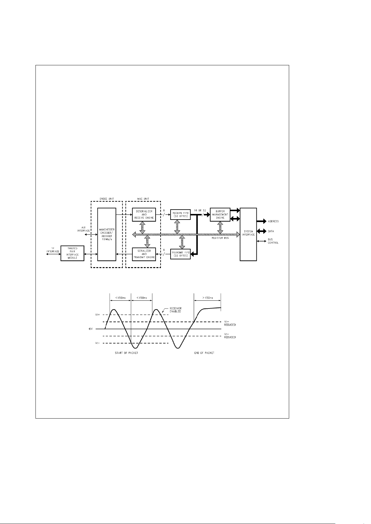
3.0 Functional Description
The SONIC-T
(Figure 3-1)
consists of a twisted pair interface (TPI) module, an encoder/decoder (ENDEC) unit, a
media access control (MAC) unit, separate receive and
transmit FIFOs, a system buffer management engine, and a
user programmable system bus interface unit on a single
chip. SONIC-T is highly pipelined providing maximum system level performance. This section provides a functional
overview of the SONIC-T.
3.1 TWISTED PAIR INTERFACE MODULE
The TPI consists of five main logic functions:
a. the Smart Squelch, which determines when valid data is
present on the differential receive inputs (RXI
g
),
b. the Collision Detector, which checks for simultaneous
transmission and reception of data on the differential
transmit output (TXO
g
) and differential receive input
(RXI
g
) pins,
c. the Link Detector/Generator, which checks the integrity
of the cable connecting the two twisted pair modules,
d. the Jabber, which disables the transmitter if it attempts to
transmit a longer than legal packet, and
e. the Transmitter, which utilizes a Transmit Driver and a
Pre-emphasis to transmit Manchester encoded data to
the twisted pair network via summing resistors and a
transformer/filter.
Smart Squelch: The SONIC-T Controller implements an intelligent receive squelch on the RXI
g
differential inputs to
ensure that impulse noise on the receive inputs will not be
mistaken for a valid signal.
The squelch circuitry employs a combination of amplitude
and timing mesurements to determine the validity of data on
the twisted pair inputs. There are two voltage level options
for the smart squelch. One mode, 10BASE-T mode
(Figure
3-2)
, uses levels that meet the 10BASE-T specification. The
second mode, reduced squelch mode, uses a lower squelch
threshold level, and can be used in longer cable applications where smaller signal levels may be applied. The
squelch level mode can be selected using the LOWSQL
input pin (see Section 2.0).
TL/F/12597– 4
FIGURE 3-1. SONIC-T Block Diagram
TL/F/12597– 5
FIGURE 3-2. Twisted Pair Squelch Waveform (10BASE-T Mode)
http://www.national.com 12
3.0 Functional Description (Continued)
The signal at the start of the packet is checked by the smart
squelch, and any pulses not exceeding the squelch level
(either positive or negative, depending upon polarity) will be
rejected. Once this first squelch level is overcome correctly,
the opposite squelch level must then be exceeded within
150 ns. Finally, the signal must exceed the original squelch
level within the next 150 ns time period to ensure that the
input waveform will not be rejected. The checking procedure typically results in the loss of three bits at the beginning of each packet.
Only after all these conditions have been satisfied will a
control signal be generated to indicate to the remainder of
the circuitry that valid data is present. At this time the smart
squelch circuitry is reset.
In the reduced squelch mode the operation is identical except that the lower squelch levels shown in
Figure 3-2
are
used.
Valid data is considered to be present until either squelch
level has not been generated for a time period of more than
150 ns indicating the End of Packet. Once good data has
been detected, the squelch levels are reduced to minimize
the effect of noise causing premature End of Packet detection.
Collision: A collision is detected by the TPI module when
the receive and transmit channels are simultaneously active. If the TPI is receiving when a collision is detected it is
reported to the controller immediately. If, however, the TPI
is transmitting when a collision is detected, the collision is
not reported until seven bits have been received while in the
collision state. This prevents a collision being reported incorrectly due to noise on the network. The signal to the
controller remains for the duration of the collision.
Approximately 1 ms after the transmission of each packet, a
signal called the Signal Quality Error (SQE) is generated
which typically consists of 10 cycles of a 10 MHz signal.
This 10 MHz signal, also called the Heartbeat, ensures the
continued functioning of the collision circuitry.
Link Detector/Generator: The link generator is a timer circuit that generates a link pulse, produced by the transmitter
section, as defined by the 10BASE-T specification. The
100 ns wide pulse is transmitted on the TXO
a
output every
16 ms in the absence of transmit data.
This link pulse is used to check the integrity of the connection to the remote MAU. The link detection circuit checks for
valid pulses that are received from the remote unit. If valid
link pulses are not received, the link detector will disable the
transmit, receive, and collision detection functions.
The LINKLED
output can directly drive a LED to show that
there is a good twisted pair link. For normal conditions the
LED will be on. The link integrity function can be disabled by
asserting the LNKDIS
input pin.
Jabber: The jabber timer monitors the transmitter and disables the transmission if the transmitter is active for greater
than 26 ms. The transmitter is then disabled for the whole
time that the ENDEC module’s internal transmit enable is
asserted. This signal has to be deasserted for approximately 750 ms (the unjab time) before the Jabber re-enables the
transmit outputs.
Transmitter: The transmitter consists of four signals, the
true and complement Manchester encoded data (TXO
g
)
and these signals delayed by 50 ns (TXOd
g
).
These four signals are resistively combined (see Section
8.2), TXO
a
with TXOdband TXObwith TXOda, in a configuration referred to as pre-emphasis. This digital pre-emphasis is required to compensate for the low-pass filter effects of the twisted pair cable which causes greater attenuation to the 10 MHz (50 ns) pulses of the Manchester encoded waveform than the 5 MHz (100 ns) pulses.
TL/F/12597– 6
FIGURE 3-3. Typical Summed Transmit Waveform
The signal with pre-emphasis is generated by resistively
combining TXO
a
and TXOd
b
(Figure 3-3)
. This signal
along with its complement is passed to the transmit filter.
Status Information: Status information is provided by the
SONIC-T Controller on the RXLED
, TXLED, COLED,
LINKLED
, and POLED outputs as described in the pin de-
scription table. These outputs
(Figure 3-4)
are suitable for
driving status LEDs.
TL/F/12597– 7
FIGURE 3-4. Typical SONIC-T LED Connection
http://www.national.com13

3.0 Functional Description (Continued)
3.2 IEEE 802.3 ENCODER/DECODER (ENDEC) UNIT
The Encoder/Decoder (ENDEC) unit is the interface between either the Twisted Pair Interface Module or the Ethernet transceiver and the Media Access Control (MAC) unit.
Providing the Manchester data encoding and decoding
functions for IEEE 802.3 Ethernet, Thin-Ethernet, or Twisted
Pair types of local area networks, the ENDEC operations of
SONIC-T are identical to those of the DP83910A CMOS
Serial Network Interface device. During transmission, the
ENDEC unit combines non-return-zero (NRZ) data from the
MAC section and clock pulses to produce Manchester data
and sends the converted data differentially to the transceiver. Conversely, during reception, an analog Phase Lock
Loop (PLL) decodes the Manchester data into both NRZ
formatted data and a receive clock. The SONIC-T ENDEC
unit is a functionally complete Manchester encoder/decoder incorporating a balanced driver and receiver, an on-board
crystal oscillator, a collision signal translator, and a diagnostic loopback. The features include:
#
Compatibility with Ethernet I and II, IEEE 802.3
10BASE5, 10BASE2, and 10BASE-T
#
10Mb/s Manchester encoding/decoding with receive
clock recovery
#
No precision components requirement
#
Loopback capability for diagnostics
#
Squelch circuitry at the receive and collision inputs reject
noise
#
Connection to the transceiver (Attachment Unit Interface) cable via external pulse transformer
3.2.1 ENDEC Operation
The primary function of the ENDEC unit
(Figure 3-5)
is to
perform the encoding and decoding necessary for compatibility between the differential pair Manchester encoded data
of the transceiver and the Non-Return-to-Zero (NRZ) serial
data of the MAC unit data line. In addition to encoding and
decoding the data stream, the ENDEC also supplies all of
the special signals (e.g., collision detect, carrier sense, and
clocks) necessary to the MAC unit. The signals provided to
the MAC unit from the on-chip ENDEC are also provided as
outputs to the user.
Manchester Encoder and Differential Output Driver:
During transmission to the network, the ENDEC unit translates the NRZ serial data from the MAC unit into differential
pair Manchester encoded data. To perform this operation
the NRZ bit stream from the MAC unit is passed through the
Manchester encoder block of the ENDEC unit. Once the bit
stream is encoded, it is transmitted out differentially to the
transmit differential pair through the transmit driver.
The SONIC-T Controller is compatible with the IEEE 802.3
‘‘full-step’’ standard. That is, the Transmit
a
and Transmit
b
differential outputs are at equal voltages while they are idle
at the primary of the isolation transformer at the network
interface. This voltage relationship provides a zero differential voltage for operation with transformer coupled loads.
(See Section 8.1 for network interfacing considerations.)
Manchester Decoder: During reception from the network,
the differential receive data from the transceiver is converted from Manchester encoded data into NRZ serial data and
a receive clock, which are sent to the receive data and
clock inputs of the MAC unit. To perform this operation, the
signal is passed to the PLL decoder block once it is received from the differential receiver. The PLL decodes the
data and generates a data receive clock and a NRZ serial
data stream to the MAC unit.
Data typically becomes valid from the decoder within 6 bit
times, and the decoder detects the end of a frame when no
more mid-bit transitions are detected. (See Section 8.1 for
network interfacing considerations.)
Special Signals: In addition to performing the Manchester
encoding and decoding function, the ENDEC unit provides
control and clocking signals to the MAC unit. The ENDEC
sends a carrier sense (CRS) signal that indicates to the
MAC unit that data is present from the network on the
ENDEC’s receive differential pair. When the ENDEC’s collision receiver detects a 10 MHz signal on the differential
collision input pair, the ENDEC unit provides the MAC unit
with a collision detection signal (COL). COL indicates that a
collision is taking place somewhere on the network.
http://www.national.com 14
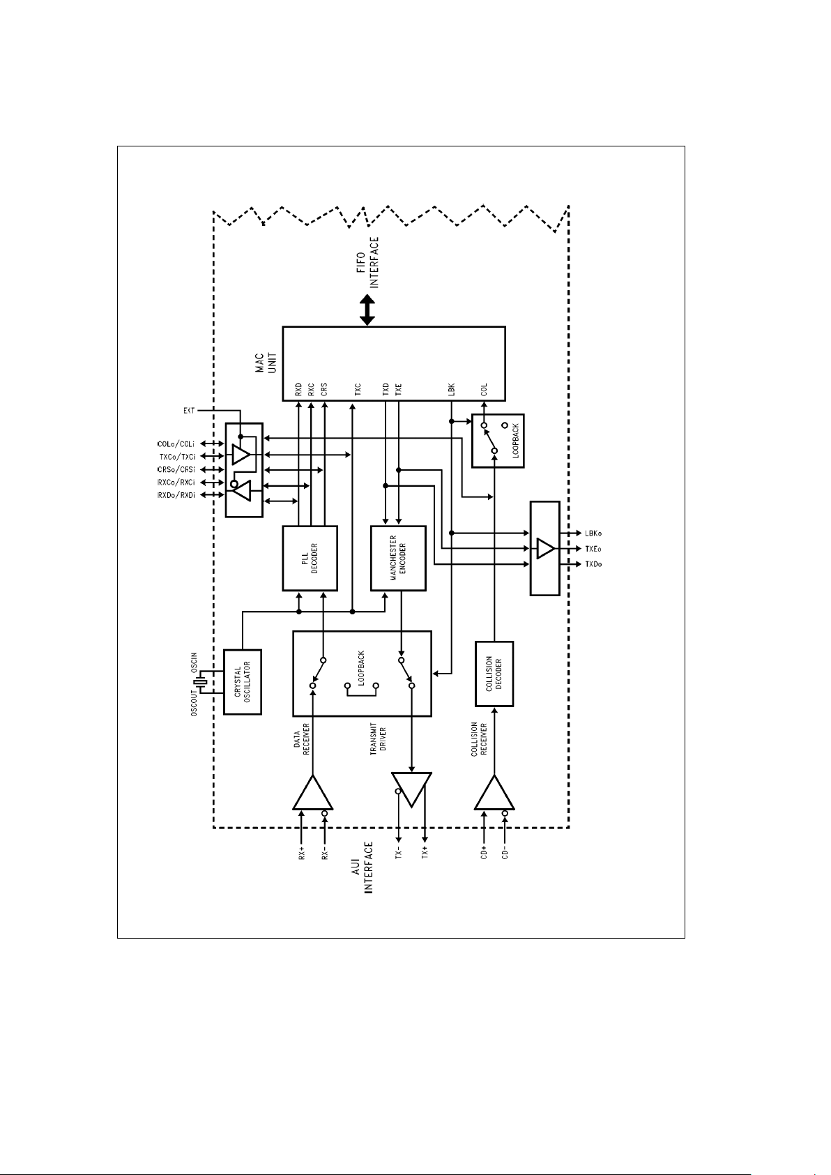
3.0 Functional Description (Continued)
TL/F/12597– 8
FIGURE 3-5. Block Diagram of Ethernet ENDEC
http://www.national.com15
3.0 Functional Description (Continued)
The ENDEC also provides both the receive and transmit
clocks to the MAC unit. The transmit clock is one half of the
oscillator input and the receive clock is extracted from the
input data by the PLL.
Oscillator: The oscillator generates the 10 MHz transmit
clock signal for network timing. The oscillator is controlled
by a parallel resonant crystal or by an external clock (see
Section 8.1.3). The 20 MHz output of the oscillator is divided
by 2 to generate the 10 MHz transmit clock (TXC) for the
MAC section. The oscillator also provides an internal clock
signal for the encoding and decoding circuits.
Loopback Functions: The SONIC-T provides three loopback modes which allow for loopback testing at the MAC,
ENDEC and external transceiver level (see Section 3.7 for
details). It is important to note that when the SONIC-T is
transmitting, the transmitted packet will always be looped
back by the external transceiver. The SONIC-T takes advantage of this to monitor the transmitted packet. See the
explanation of the Receive State Machine in Section 3.3.1
for more information about monitoring transmitted packets.
3.2.2 Selecting an External ENDEC
An option is provided on SONIC-T to disable the on-chip
ENDEC unit and use an external ENDEC. The internal IEEE
802.3 ENDEC can be bypassed by connecting the EXT pin
to V
CC
(EXTe1). In this mode the MAC signals are redirected out from the chip, allowing an external ENDEC to be
used. See Section 2.0 for the alternate pin definitions.
3.3 MEDIA ACCESS CONTROL (MAC) UNIT
The Media Access Control (MAC) unit performs the control
functions for the media access of transmitting and receiving
packets over Twisted Pair or AUI. During transmission, the
MAC unit frames information from the transmit FIFO and
supplies serialized data to the ENDEC unit. During reception, the incoming information from the ENDEC unit is deserialized, the frame checked for valid reception, and the data
is transferred to the receive FIFO. Control and status registers on the SONIC-T govern the operation of the MAC unit.
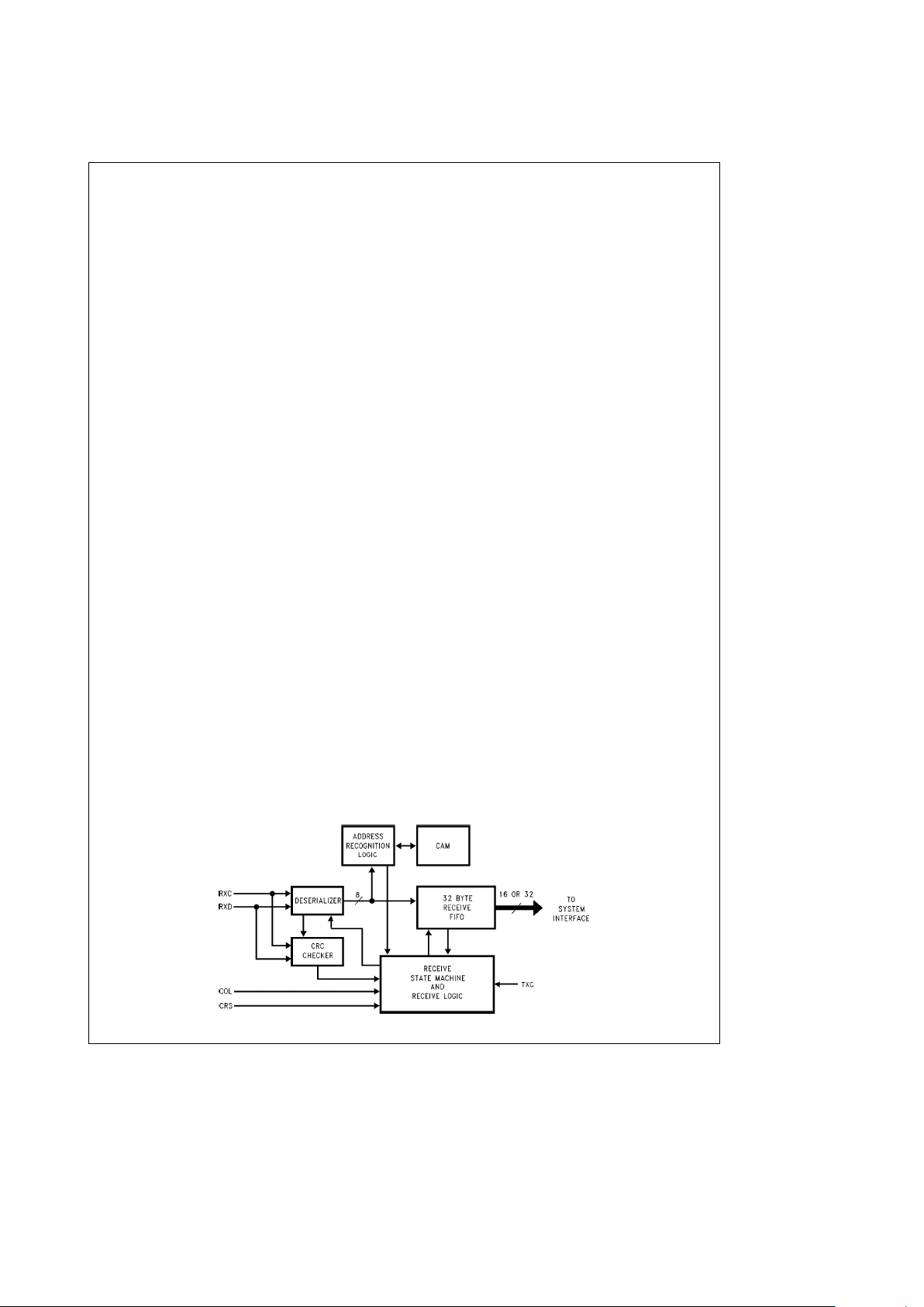
3.3.1 MAC Receive Section
The receive section
(Figure 3-6)
controls the MAC receive
operations during reception, loopback, and transmission.
During reception, the deserializer goes active after detecting
the 2-bit Start of Frame Delimiter (SFD) pattern (see Section
4.1). It then frames the incoming bits into octet boundaries
and transfers the data to the 32-byte receive FIFO. Concurrently the address comparator compares the Destination
Address Field to the addresses stored in the chip’s Content
Addressable Memory (CAM) address registers. If a match
occurs, the deserializer passes the remainder of the packet
to the receive FIFO. The packet is decapsulated when the
carrier sense input pin (CRS) goes inactive. At the end of
reception the receive section checks the following:
Ð Frame alignment errors
Ð CRC errors
Ð Length errors (runt packets)
The appropriate status is indicated in the Receive Control
register (see Section 6.4.3). In loopback operations, the receive section operates the same as during normal reception.
During transmission, the receive section remains active to
allow monitoring of the self-received packet. The Cyclic Redundancy Code (CRC) checker operates as normal, and the
Source Address field is compared with the CAM address
entries. Status of the CRC check and the source address
comparison is indicated by the PMB bit in the Transmit Control register (see Section 6.4.4). No data is written to the
receive FIFO during transmit operations.
The receive section consists of the following blocks detailed
below.
Receive State Machine (RSM): The RSM insures the proper sequencing for normal reception and self-reception during transmission. When the network is inactive, the RSM
remains in an idle state continually monitoring for network
activity. If the network becomes active, the RSM allows the
deserializer to write data into the receive FIFO. During this
state, the following conditions may prevent the complete
reception of the packet.
Ð FIFO OverrunÐThe receive FIFO has been completely
filled before the SONIC-T could buffer the data to memory.
Ð CAM Address MismatchÐThe packet is rejected be-
cause of a mismatch between the destination address of
the packet and the address in the CAM.
Ð Memory Resource ErrorÐThere are no more resources
(buffers or descriptors) available for buffering the incoming packets.
Ð Collision or Other ErrorÐA collision occurred on the net-
work or some other error, such as a CRC error, occurred
(this is true if the SONIC-T has been told to reject pack-
ets on a collision, or reject packets with errors).
If these conditions do not occur, the RSM processes the
packet indicating the appropriate status in the Receive Control register.
TL/F/12597– 9
FIGURE 3-6. MAC Receiver
http://www.national.com 16
3.0 Functional Description (Continued)
During transmission of a packet from the SONIC-T, the
transceiver will always loop the packet back to the
SONIC-T. The SONIC-T will use this to monitor the packet
as it is being transmitted. The CRC and source address of
the looped back packet are checked with the CRC and
source address that were transmitted. If they do not match,
an error bit is set in the status of the transmitted packet (see
Packet Monitored Bad, PMB, in the Transmit Control Register, Section 6.4.4). Data is not written to the receive FIFO
during this monitoring process unless a Loopback mode has
been selected (see Section 3.7).
Receive Logic: The receive logic contains the command,
control, and status registers that govern the operations of
the receive section. It generates the control signals for writing data to the receive FIFO, processes error signals obtained from the CRC checker and the deserializer, activates
the ‘‘packet reject’’ signal to the RSM for rejecting packets,
and posts the applicable status in the Receive Control register.
Deserializer: This section deserializes the serial input data
stream and provides a byte clock for the address comparator and receive logic. It also synchronizes the CRC checker
to begin operation (after SFD is detected), and checks for
proper frame alignment with respect to CRS going inactive
at the end of reception.
Address Comparator: The address comparator latches the
Destination Address (during reception or loopback) or
Source Address (during transmission) and determines
whether the address matches one of the entries in the CAM.
CRC Checker: The CRC checker calculates the 4-byte
Frame Check Sequence (FCS) field from the incoming data
stream and compares it with the last 4-bytes of the received
packet. The CRC checker is active for both normal reception and self-reception during transmission.
Content Addressable Memory (CAM): The CAM contains
16 user programmable entries and 1 pre-programmed
Broadcast address entry for complete filtering of received
packets. The CAM can be loaded with any combination of
Physical and Multicast Addresses (see Section 4.2). See
Section 6.1 for the procedure on loading the CAM registers.
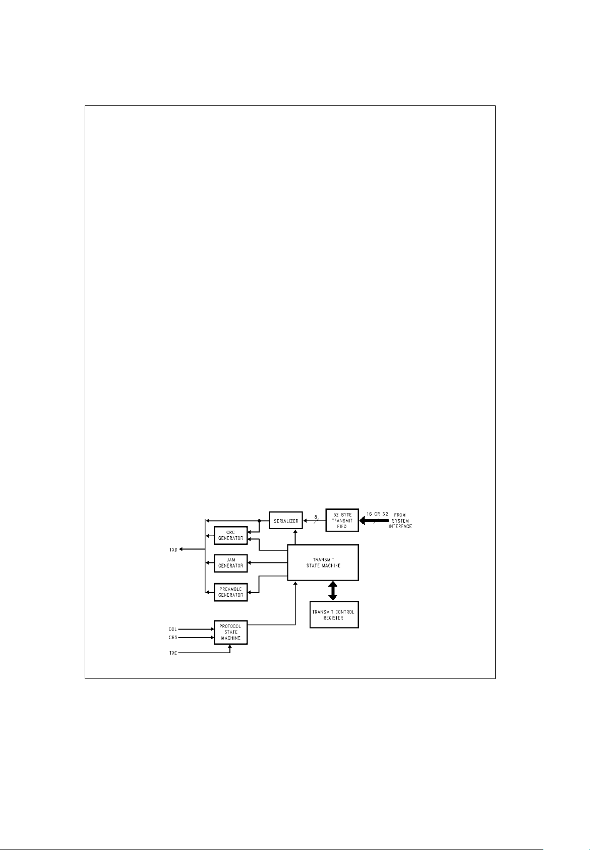
3.3.2 MAC Transmit Section
The transmit section
(Figure 3-7)
is responsible for reading
data from the transmit FIFO and transmitting a serial data
stream onto the network in conformance with the IEEE
802.3 Carrier Sense Multiple Access with Collision Detection (CSMA/CD) standard. The Transmit Section consists of
the following blocks.
Transmit State Machine (TSM): The TSM controls the
functions of the serializer, preamble generator, and JAM
generator. It determines the proper sequence of events that
the transmitter follows under various network conditions. If
no collision occurs, the transmitter prefixes a 62-bit preamble and 2-bit Start of Frame Delimiter (SFD) at the beginning
of each packet and then sends the serialized data. At the
end of the packet, an optional 4-byte CRC pattern is appended. If a collision occurs, the transmitter switches from
transmitting data to sending a 4-byte Jam pattern to notify
all nodes that a collision has occurred. Should the collision
occur during the preamble, the transmitter waits for it to
complete before jamming. After the transmission has completed, the transmitter writes status in the Transmit Control
register (see Section 6.4.4).
Protocol State Machine: The protocol state machine assures that the SONIC-T obeys the CSMA/CD protocol. Before transmitting, this state machine monitors the carrier
sense and collision signals for network activity. If any other
nodes are currently transmitting, the SONIC-T defers its
transmission until the network is quiet. It then transmits after
its Interframe Gap Timer (9.6 ms) has expired. The Interframe Gap time is divided into two portions. During the first
6.4 ms, any new network activity will restart the Interframe
Gap timer. Beyond this time, however, network activity is
ignored and the state machine waits the remaining 3.2 ms
before transmitting. If the SONIC-T experiences a collision
during a transmission, it switches from transmitting data to
transmitting a 4-byte JAM pattern (4 bytes of all 1’s), before
ceasing to transmit. The SONIC-T then waits a random
number of slot times (51.2 ms) determined by the
Truncated
Binary Exponential Backoff Algorithm
before reattempting
another transmission. In this algorithm, the number of slot
times to delay before the nth retransmission is chosen to be
a random integer r in the range of:
0
srs
2
k
where kemin(n,10)
If a collision occurs on the 16th transmit attempt, the
SONIC-T aborts transmitting the packet and reports an ‘‘Excessive Collisions’’ error in the Transmit Control register.
TL/F/12597– 10
FIGURE 3-7. MAC Transmitter
http://www.national.com17
3.0 Functional Description (Continued)
Serializer: After data has been written into the 32-byte
transmit FIFO, the serializer reads byte wide data from the
FIFO and sends a NRZ data stream to the Manchester encoder. The rate at which data is transmitted is determined
by the transmit clock (TXC). The serialized data is transmitted after the SFD.
Preamble Generator: The preamble generator prefixes a
62-bit alternating ‘‘1,0’’ pattern and a 2-bit ‘‘1,1’’ SFD pattern at the beginning of each packet. This allows receiving
nodes to synchronize to the incoming data. The preamble is
always transmitted in its entirety even in the event of a collision. This assures that the minimum collision fragment is 96
bits (64 bits of normal preamble, and 4 bytes, or 32 bits of
JAM pattern).
CRC Generator: The CRC generator calculates the 4-byte
FCS field from the transmitted serial data stream. If enabled, the 4-byte FCS field is appended to the end of the
transmitted packet (see Section 4.6).
For bridging or switched ethernet applications the CRC
Generator can be inhibited by setting bit 13 in the Transmit
Control Register (Section 6.4.4). This feature is used when
an ethernet segment has already received a packet with a
CRC appended and needs to forward it another ethernet
segment.
Jam Generator: The Jam generator produces a 4-byte pattern of all 1’s to assure that all nodes on the network sense
the collision. When a collision occurs, the SONIC-T stops
transmitting data and enables the Jam generator. If a collision occurs during the preamble, the SONIC-T finishes
transmitting the preamble before enabling the Jam generator (see Preamble Generator above).
3.3.3 Full Duplex Operation
When configured for Full Duplex operation the TSM and
RSM allow simultaneous transmission and reception of
packets. In Full Duplex mode the RSM operates as described earlier. Transmitted packets won’t be monitored.
The TSM will operate as described earlier, except that the
activity on the receive inputs will be ignored.
3.4 DATA WIDTH AND BYTE ORDERING
The SONIC-T can be programmed to operate with either
32-bit or 16-bit wide memory. The data width is configured
during initialization by programming the DW bit in the Data
Configuration Register (DCR) (see Section 6.4.2). If the
16-bit data path is selected, data is driven on pins D15 – D0.
The SONIC-T also provides both Little Endian and Big Endian byte-ordering capability for compatibility with National/Intel or Motorola microprocessors respectively by selecting
the proper level on the Bus Mode (BMODE) pin.
Little Endian (National/Intel) Mode (BMODE
e
0): The
byte orientation for received and transmitted data in the Receive Buffer Area (RBA) and Transmit Buffer Area (TBA) of
system memory is as follows:
16-Bit Word
15 8 7 0
Byte 1 Byte 0
MSB LSB
32-Bit Long Word
31 24 23 16 15 8 7 0
Byte 3 Byte 2 Byte 1 Byte 0
MSB LSB
Big Endian (Motorola) Mode (BMODE
e
1): The byte orientation for received and transmitted data in the RBA and
TBA is as follows:
16-Bit Word
15 8 7 0
Byte 0 Byte 1
LSB MSB
32-Bit Long Word
31 24 23 16 15 8 7 0
Byte 0 Byte 1 Byte 2 Byte 3
LSB MSB
3.5 FIFO AND CONTROL LOGIC
The SONIC-T incorporates two independent 32-byte FIFOs
for transferring data to/from the system interface and from/
to the network. The FIFOs, providing temporary storage of
data, free the host system from the real-time demands on
the network.
The way in which the FIFOS are emptied and filled is controlled by the FIFO threshold values and the Block Mode
Select bits (BMS) (see Section 6.4.2). The threshold values
determine how full or empty the FIFOs are allowed to be
before the SONIC-T will request access of the bus to get
more data from memory or buffer more data to memory.
When Block Mode is enabled, the number of bytes transferred is determined by the threshold value. For example, if
the threshold for the receive FIFO is 4 words, then the SONIC-T will always transfer 4 words from the receive FIFO to
memory. If Empty/Fill mode is enabled, however, the number of bytes transferred is the number required to fill the
transmit FIFO or empty the receive FIFO. The manner in
which the threshold affects reception and transmission of
packets is discussed below in Sections 3.5.1 and 3.5.2.
3.5.1 Receive FIFO
To accommodate the different transfer rates, the receive
FIFO
(Figure 3-8)
serves as a buffer between the 8-bit network (deserializer) interface and the 16/32-bit system interface. The FIFO is arranged as a 4-byte wide by 8 deep
memory array (8-long words, or 32 bytes) controlled by
three sections of logic. During reception, the Byte Ordering
logic directs the byte stream from the deserializer into the
FIFO using one of four write pointers. Depending on the
selected byte-ordering mode, data is written either least significant byte first or most significant byte first to accommodate little or big endian byte-ordering formats respectively.
As data enters the FIFO, the Threshold Logic monitors the
number of bytes written in from the deserializer. The programmable threshold (RFT1,0 in the Data Configuration
Register, see Section 6.4.2) determines the number of
words (or long words) written into the FIFO from the MAC
unit before a direct memory access (DMA) request for system memory occurs. When the threshold is reached, the
http://www.national.com 18
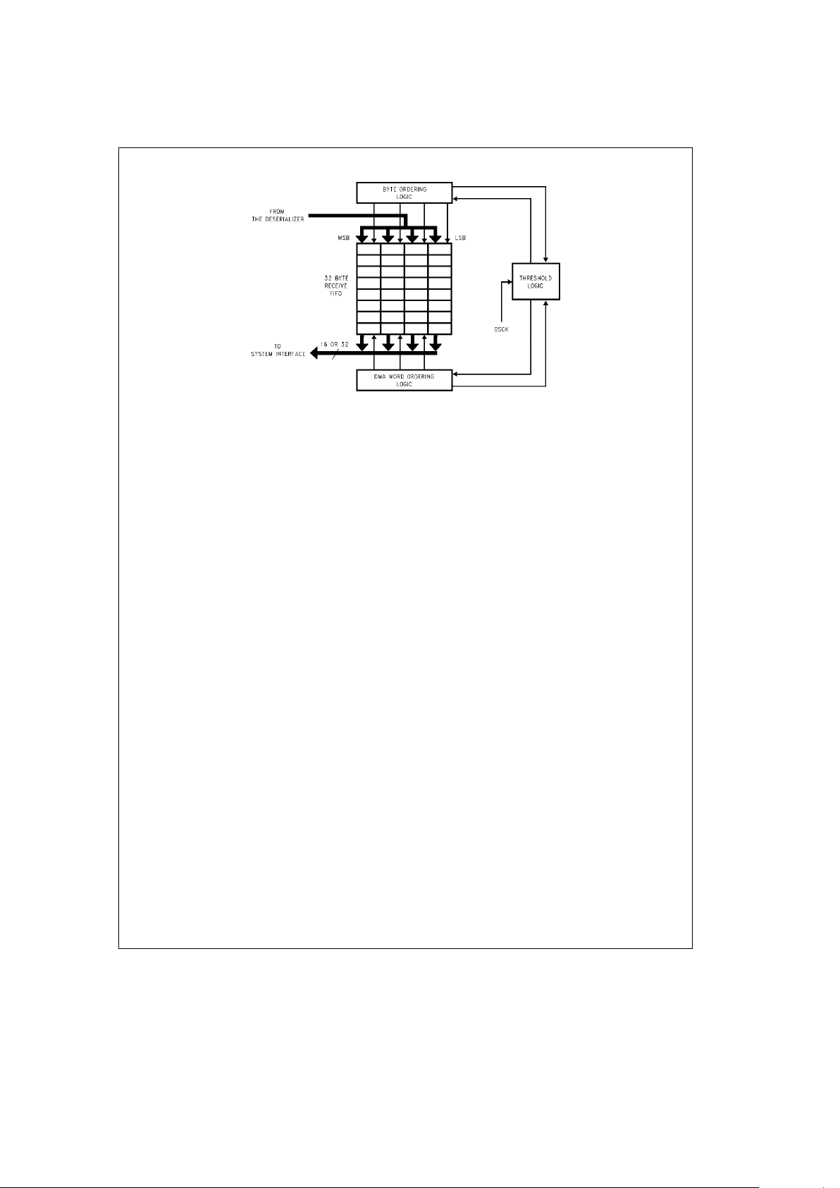
3.0 Functional Description (Continued)
TL/F/12597– 11
FIGURE 3-8. Receive FIFO
Threshold Logic enables the Buffer Management Engine to
read a programmed number of 16- or 32-bit words (depending upon the selected data width) from the FIFO and transfer them to the system interface (the system memory) using
DMA. The threshold is reached when the number of bytes in
the receive FIFO is greater than the value of the threshold.
For example, if the threshold is 4 words (8 bytes), then the
Threshold Logic will not cause the Buffer Management Engine to write to memory until there are more than 8 bytes in
the FIFO.
The Buffer Management Engine reads either the upper or
lower half (16 bits) of the FIFO in 16-bit mode or reads the
complete long word (32 bits) in 32-bit mode. If, after the
transfer is complete, the number of bytes in the FIFO is less
than the threshold, then the SONIC-T is done. This is always the case when the SONIC-T is in Empty/Fill Mode. If,
however, for some reason (e.g., latency on the bus) the
number of bytes in the FIFO is still greater than the threshold value, the Threshold Logic will cause the Buffer Management Engine to do a DMA request to write to memory
again. This latter case is usually only possible when the
SONIC-T is in Block Mode.
When in Block Mode, each time the SONIC-T requests the
bus, only a number of bytes equal to the threshold value will
be transferred. The Threshold Logic continues to monitor
the number of bytes written in from the deserializer and enables the Buffer Management Engine every time the threshold has been reached. This process continues until the end
of the packet.
Once the end of the packet has been reached, the serializer
will fill out the last word (16-bit mode) or long word (32-bit
mode) if the last byte did not end on a word or long word
boundary respectively. The fill byte will be 0FFh. Immediately after the last byte (or fill byte) in the FIFO, the received
packets status will be written into the FIFO. The entire packet, including any fill bytes and the received packet status will
be buffered to memory. When a packet is buffered to memory by the Buffer Management Engine, it is always taken
from the FIFO in words or long words and buffered to memory on word (16-bit mode) or long word (32-bit mode)
boundaries. Data from a packet cannot be buffered on odd
byte boundaries for 16-bit mode, and odd word boundaries
for 32-bit mode (see Section 5.3). For more information on
the receive packet buffering process, see Section 5.4.
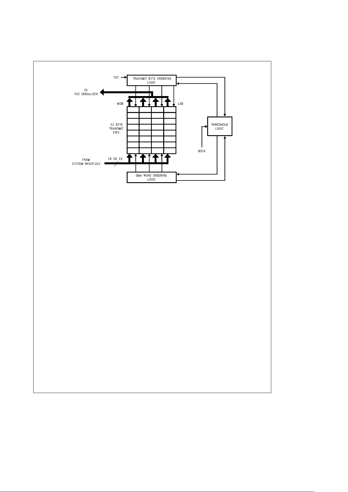
3.5.2 Transmit FIFO
Similar to the Receive FIFO, the Transmit FIFO
(Figure 3-9)
serves as a buffer between the 16/32-bit system interface
and the network (serializer) interface. The Transmit FIFO is
also arranged as a 4 byte by 8 deep memory array (8 long
words or 32 bytes) controlled by three sections of logic.
Before transmission can begin, the Buffer Management Engine fetches a programmed number of 16- or 32-bit words
from memory and transfers them to the FIFO. The Buffer
Management Engine writes either the upper or lower half
(16 bits) into the FIFO for 16-bit mode or writes the complete long word (32 bits) during 32-bit mode.
The Threshold Logic monitors the number of bytes as they
are written into the FIFO. When the threshold has been
reached, the Transmit Byte Ordering state machine begins
reading bytes from the FIFO to produce a continuous byte
stream for the serializer. The threshold is met when the
number of bytes in the FIFO is greater than the value of the
threshold. For example, if the transmit threshold is 4 words
(8 bytes), the Transmit Byte Ordering state machine will not
begin reading bytes from the FIFO until there are 9 or more
bytes in the buffer. The Buffer Management Engine continues replenishing the FIFO until the end of the packet. It
does this by making multiple DMA requests to the system
interface. Whenever the number of bytes in the FIFO is
equal to or less than the threshold value, the Buffer Management Engine will do a DMA request. If Block Mode is
set, then after each request has been granted by the system, the Buffer Management Engine will transfer a number
of bytes equal to the threshold value into the FIFO. If Empty/Fill Mode is set, the FIFO will be completely filled in one
DMA request.
Since data may be organized in big or little endian byte ordering format, the Transmit Byte Ordering state machine
uses one of four read pointers to locate the proper byte
within the 4 byte wide FIFO. It also determines the valid
number of bytes in the FIFO. For packets which begin or
end at odd bytes in the FIFO, the Buffer Management Engine writes extraneous bytes into the FIFO. The Transmit
Byte Ordering state machine detects these bytes and only
transfers the valid bytes to the serializer. The Buffer Management Engine can read data from memory on any byte
boundary (see Section 5.3). See Section 5.5 for more information on transmit buffering.
http://www.national.com19
3.0 Functional Description (Continued)
TL/F/12597– 12
FIGURE 3-9. Transmit FIFO
3.6 STATUS AND CONFIGURATION REGISTERS
The SONIC-T contains a set of status/control registers for
conveying status and control information to/from the host
system. The SONIC-T uses these registers for loading commands generated from the system, indicating transmit and
receive status, buffering data to/from memory, and providing interrupt control. Each register is 16 bits in length. See
Section 6.0 for a description of the registers.
3.7 BUS INTERFACE
The system interface
(Figure 3-10)
consists of the pins necessary for interfacing to a variety of buses. It includes the
I/O drivers for the data and address lines, bus access control for standard microprocessors, ready logic for synchronous or asynchronous systems, slave access control, interrupt control, and shared-memory access control. The functional signal groups are shown in
Figure 3-10
. See Section
7.0 for a complete description of the SONIC-T bus interface.
3.8 LOOPBACK AND DIAGNOSTICS
The SONIC-T provides three loopback modes for self-testing from the controller interface to the transceiver interface.
The loopback function is provided to allow self-testing of the
chip’s internal transmit and receive operations. During loopback, transmitted packets are routed back to the receive
section of the SONIC-T where they are filtered by the address recognition logic and buffered to memory if accepted.
Transmit and receive status and interrupts remain active
during loopback. This means that when using loopback, it is
as if the packet was transmitted and received by two separate chips that are connected to the same bus and memory.
MAC Loopback: Transmitted data is looped back at the
MAC. Data is not sent from the MAC to either the internal
ENDEC or an external ENDEC (the external ENDEC interface pins will not be driven), hence, data is not transmitted
from the chip. Even though the ENDEC is not used in MAC
loopback, the ENDEC clock (an oscillator or crystal for the
internal ENDEC or TXC for an external ENDEC) must be
driven. Network activity, such as a collision, does not affect
MAC loopback, and the CSMA/CD MAC protocol is not
completely followed.
ENDEC Loopback: Transmitted data is looped back at the
ENDEC. If the internal ENDEC is used, data is switched
from the transmit section of the ENDEC to the receive section
(Figure 3-5)
. Data is not transmitted from the chip and
the collision lines, CD
g
, are ignored, hence, network activity does not affect ENDEC loopback. The LBK signal from
the MAC tells the internal ENDEC to go into loopback mode.
If an external ENDEC is used, it should operate in loopback
mode when the LBK signal is asserted. CSMA/CD MAC
protocol is followed even though data is not transmitted
from the chip.
Transceiver Loopback: Transmitted data is looped back at
the external transceiver (which is always the case regardless of the SONIC-T’s loopback mode). CSMA/CD MAC
protocol is followed since data will be transmitted from the
chip. This means that transceiver loopback is affected by
network activity. The basic difference between Transceiver
Loopback Mode and the other loopback modes is that the
SONIC-T loads the receive FIFO and buffers the packet to
memory. In normal operations, the SONIC-T only monitors
the packet that is looped back by the transceiver, but does
not fill the receive FIFO and buffer the packet.
3.8.1 Loopback Procedure
The following procedure describes the loopback operation.
1. Initialize the Transmit and Receive Area as described in
Sections 5.4 and 5.5.
2. Load one of the CAM address registers (see Section 6.1),
with the Destination Address of the packet if you are verifying the SONIC-T’s address recognition capability.
3. Load one of the CAM address registers with the Source
Address of the packet if it is different than the Destination
Address to avoid getting a Packet Monitored Bad (PMB)
error in the Transmit Status (see Section 6.4.4).
http://www.national.com 20
3.0 Functional Description (Continued)
4. Program the Receive Control register with the desired receive filter and the loopback mode (LB1, LB0). In case of
transceiver loopback, besides setting LB1 and LB0 to 1,
the XWRAP bit in the DCR2 must also set to 1.
5. Issue the transmit command (TXP) and enable the receiver (RXEN) in the Command register.
The SONIC-T completes the loopback operation after the
packet has been completely received (or rejected if there is
an address mismatch). The Transmit Control and Receive
Control registers treat the loopback packet as it would in
normal operation and indicate status accordingly. Interrupts
are also generated if enabled in the Interrupt Mask register.
Note: For MAC Loopback, only one packet may be queued up for proper
operation. This restriction occurs because the transmit MAC section,
which does not generate an Interframe Gap (IFG) time between
transmitted packets, does not allow the receive MAC section to update receive status. There are no restrictions for the other loopback
modes.
3.9 NETWORK MANAGEMENT FUNCTIONS
The SONIC-T fully supports the Layer Management IEEE
802.3 standard to allow a node to monitor the overall performance of the network. These statistics are available on a
per packet basis at the end of reception or transmission.
In addition, the SONIC-T provides three tally counters to
tabulate CRC errors, Frame Alignment errors, and missed
packets. Table 3-1 shows the statistics indicated by the
SONIC-T.
TL/F/12597– 13
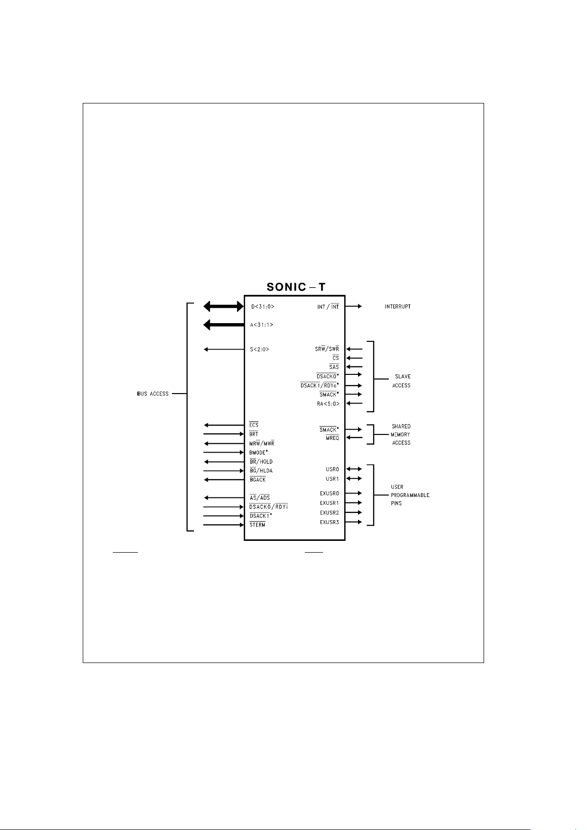
*Note: DSACK0,1 are used for both Bus and Slave Access Control and are bidirectional. SMACK is used for both Slave access and shared memory access. The
BMODE pin selects between National/Intel or Motorola type busses.
FIGURE 3-10. SONIC-T Bus Interface Signals
http://www.national.com21
3.0 Functional Description (Continued)
TABLE 3-1. Network Management Statistics
Statistic Register Used Bits Used
Frames Transmitted OK TCR (Note) PTX
Single Collision Frames (Note) NC0–NC4
Multiple Collision Frames (Note) NC0–NC4
Collision Frames (Note) NC0–NC4
Frames with Deferred Transmissions TCR (Note) DEF
Late Collisions TCR (Note) OWC
Excessive Collisions TCR (Note) EXC
Excessive Deferral TCR (Note) EXD
Internal MAC Transmit Error TCR (Note) BCM,FU
Frames Received OK RCR (Note) PRX
Multicast Frames Received OK RCR (Note) MC
Broadcast Frames Received OK RCR (Note) BC
Frame Check Sequence Errors CRCT All
RCR CRC
Alignment Errors FAET All
RCR FAE
Note: The number of collisions and the contents of the Transmit Control register are posted in the TXpkt.status field (see
Section 5.5.1.2). The contents of the Receive Control register are posted in the RXpkt.status field (see Section 5.4.3).
4.0 Transmit/Receive IEEE 802.3 Frame Format
A standard IEEE 802.3 packet
(Figure 4-1)
consists of the
following fields: preamble, Start of Frame Delimiter (SFD),
destination address, source address, length, data and
Frame Check Sequence (FCS). The typical format is shown
in
Figure 4-1
. The packets are Manchester encoded and
decoded by the ENDEC unit and transferred serially to/from
the MAC unit using NRZ data with a clock. All fields are of
fixed length except for the data field. The SONIC-T generates and appends the preamble, SFD and FCS field during
transmission. The Preamble and SFD fields are stripped
during reception. (The CRC is passed through to buffer
memory during reception.)
4.1 PREAMBLE AND START OF FRAME DELIMITER
(SFD)
The Manchester encoded alternating 1,0 preamble field is
used by the ENDEC to acquire bit synchronization with an
incoming packet. When transmitted, each packet contains
62 bits of an alternating 1,0 preamble. Some of this preamble may be lost as the packet travels through the network.
Byte alignment is performed when the Start of Frame Delimiter (SFD) pattern, consisting of two consecutive 1’s, is detected.
4.2 DESTINATION ADDRESS
The destination address indicates the destination of the
packet on the network and is used to filter unwanted pack-
Note: Bebytes
bebits TL/F/12597– 14
FIGURE 4-1. IEEE 802.3 Packet Structure
http://www.national.com 22

4.0 Transmit/Receive IEEE 802.3 Frame Format (Continued)
ets from reaching a node. There are three types of address
formats supported by the SONIC-T: Physical, Multicast, and
Broadcast.
Physical Address: The physical address is a unique address that corresponds only to a single node. All physical
addresses have the LSB of the first byte of the address set
to ‘‘0’’. These addresses are compared to the internally
stored CAM (Content Addressable Memory) address entries. All bits in the destination address must match an entry
in the CAM in order for the SONIC-T to accept the packet.
Multicast Address: Multicast addresses, which have the
LSB of the first byte of the address set to ‘‘1’’, are treated
similarly as physical addresses, i.e., they must match an
entry in the CAM. This allows perfect filtering of Multicast
packets and eliminates the need for a hashing algorithm for
mapping Multicast packets.
Broadcast Address: If the address consists of all 1’s, it is a
Broadcast address, indicating that the packet is intended for
all nodes.
The SONIC-T also provides a promiscuous mode which allows reception of all physical address packets. Physical,
Multicast, Broadcast, and promiscuous address modes can
be selected via the Receive Control register.
4.3 SOURCE ADDRESS
The source address is the physical address of the sending
node. Source addresses cannot be multicast or broadcast
addresses. This field must be passed to the SONIC-T’s
transmit buffer from the system software. During transmission, the SONIC-T compares the Source address with its
internal CAM address entries before monitoring the CRC of
the self-received packet. If the source address of the packet
transmitted does not match a value in the CAM, the packet
monitored bad flag (PMB) will be set in the transmit status
field of the transmit descriptor (see Sections 5.5.1.2 and
6.4.4). The SONIC-T does not provide Source Address insertion. However, a transmit descriptor fragment, containing
only the Source Address, may be created for each packet.
(See Section 5.5.1.)
4.4 LENGTH/TYPE FIELD
For IEEE 802.3 type packets, this field indicates the number
of bytes that are contained in the data field of the packet.
For Ethernet I and II networks, this field indicates the type of
packet. The SONIC-T does not operate on this field.
4.5 DATA FIELD
The data field has a variable octet length ranging from 46 to
1500 bytes as defined by the Ethernet specification. Messages longer than 1500 bytes need to be broken into multiple packets for IEEE 802.3 networks. Data fields shorter
than 46 bytes require appending a pad to bring the complete frame length to 64 bytes. If the data field is padded,
the number of valid bytes are indicated in the length field.
The SONIC-T does not append pad bytes for short packets
during transmission, nor check for oversize packets during
reception. However, the user’s driver software can easily
append the pad by lengthening the TXpkt.pktÐsize field
and TXpkt.fragÐsize field(s) to at least 64 bytes (see Section 5.5.1). Although the Ethernet specification defines the
maximum number of bytes in the data field, the SONIC-T
can transmit and receive packets up to 64k bytes.
4.6 FCS FIELD
The Frame Check Sequence (FCS) is a 32-bit CRC field
calculated and appended to a packet during transmission to
allow detection of error-free packets. During reception, an
error-free packet results in a specific pattern in the CRC
generator. The AUTODIN II (X32
a
X26aX23aX22
a
X16aX12aX11aX10aX8aX7aX5aX4
a
X2aX1a1) polynomial is used for the CRC calculations.
The SONIC-T may optionally append the CRC sequence
during transmission, and checks the CRC both during normal reception and self-reception during a transmission (see
Section 3.3.1).
4.7 MAC (MEDIA ACCESS CONTROL) CONFORMANCE
The SONIC-T is designed to be compliant to the IEEE 802.3
MAC Conformance specification. The SONIC-T implements
most MAC functions in silicon and provides hooks for the
user software to handle the remaining functions. The MAC
Conformance specifications are summarized in Table 4-1.
TABLE 4-1. MAC Conformance Specifications
Conformance
Test Name
Support By
SONIC-T
User Driver
Notes
Software
Minimum Frame Size X
Maximum Frame Size X X 1
Address Generation X X 2
Address Recognition X
Pad Length Generation X X 3
Start Of Frame Delimiter X
Length Field X
Preamble Generation X
Order of Bit Transmission X
Inconsistent Frame Length X X 1
Non-Integral Octet Count X
Incorrect Frame Check
X
Sequence
Frame Assembly X
FCS Generation and Insertion X
Carrier Deference X
Interframe Spacing X
Collision Detection X
Collision Handling X
Collision Backoff and
X
Retransmission
FCS Validation X
Frame Disassembly X
Back-to-Back Frames X
Flow Control X
Attempt Limit X
Jam Size (after SFD) X
Jam Size (in Preamble) X
Note 1: The SONIC-T provides the byte count of the entire packet in the
RXpkt.byteÐcount (see Section 5.4.3). The user’s driver software may perform further filtering of the packet based upon the byte count.
Note 2: The SONIC-T does not provide Source Address insertion; however,
a transmit descriptor fragment, containing only the Source Address, may be
created for each packet. (See Section 5.5.1.)
Note 3: The SONIC-T does not provide Pad generation; however, the user’s
driver software can easily append the Pad by lengthening the TXpkt.pkt
Ð
size field and TXpkt.fragÐsize field(s) to at least 64 bytes. (See Section
5.5.1.)
http://www.national.com23
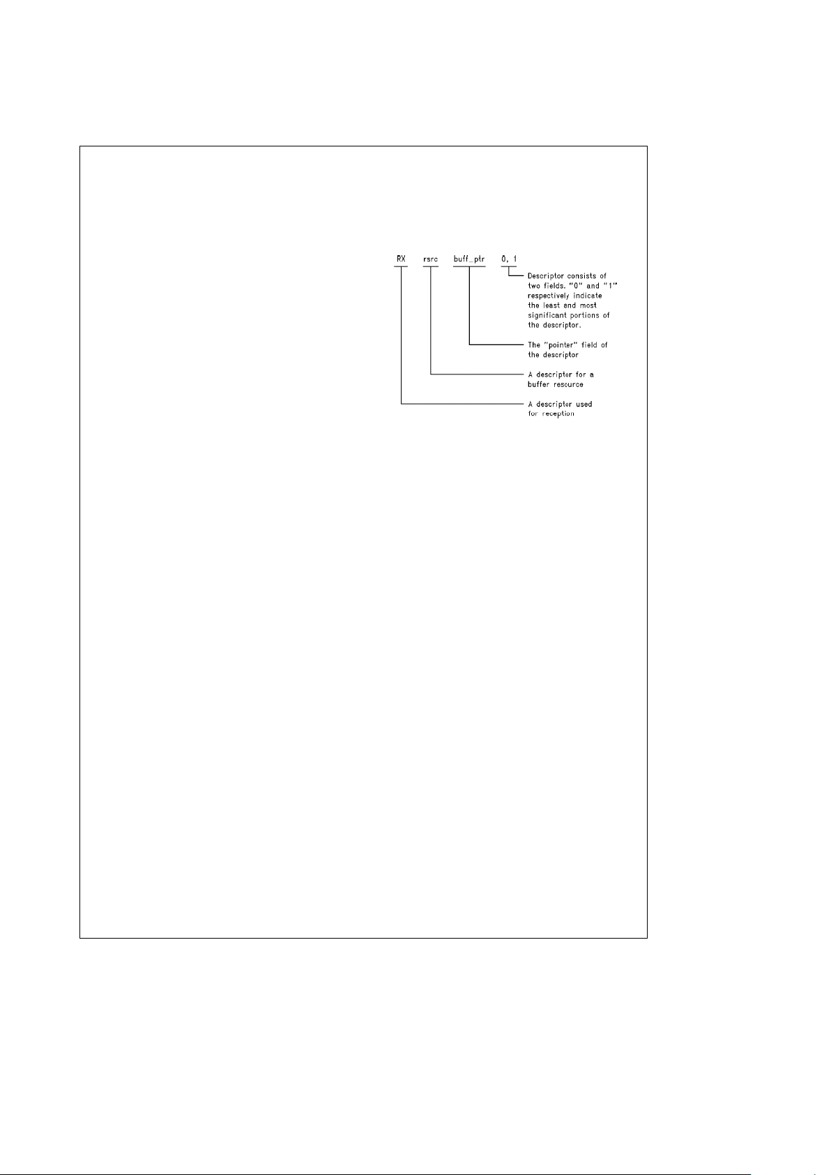
5.0 Buffer Management
5.1 BUFFER MANAGEMENT OVERVIEW
The SONIC-T’s buffer management scheme is based on
separate buffers and descriptors (
Figures 5-3
and
5-12
).
Packets that are received or transmitted are placed in buffers called the Receive Buffer Area (RBA) and the Transmit
Buffer Area (TBA). The system keeps track of packets in
these buffers using the information in the Receive Descriptor Area (RDA) and the Transmit Descriptor Area (TDA). A
single (TDA) points to a single TBA, but multiple RDAs can
point to a single RBA (one RDA per packet in the buffer).
The Receive Resource Area (RRA), which is another form
of descriptor, is used to keep track of the actual buffer.
When packets are transmitted, the system sets up the packets in one or more TBAs with a TDA pointing to each TBA.
There can only be one packet per TBA/TDA pair. A single
TBA, however, may be made up of several fragments of
data dispersed in memory. There is one TDA pointing to
each TBA which specifies information about the buffer’s
size, location in memory, number of fragments and status
after transmission. The TDAs are linked together in a linked
list. The system causes the SONIC-T to transmit the packets by passing the first TDA to the SONIC-T and issuing the
transmit command.
Before a packet can be received, an RDA and RBA must be
set up by the system. RDAs are made up as a linked list
similar to TDAs. An RDA is not linked to a particular RBA,
though. Instead, an RDA is linked specifically to a packet
after it has been buffered into an RBA. More than one packet can be buffered into the same RBA, but each packet gets
its own RDA. A received packet can not be scattered into
fragments. The system only needs to tell the SONIC-T
where the first RDA and where the RDAs are. Since an RDA
never specifically points to an RBA, the RRA is used to
keep track of the RBAs. The RRA is a circular queue of
pointers and buffer sizes (not a linked list). When the
SONIC-T receives a packet, it is buffered into an RBA and a
unique corresponding RDA is written to so that it points to
and describes the new packet. If the RBA does not have
enough space to buffer the next packet, a new RBA is obtained from the RRA.
5.2 DESCRIPTOR AREAS
Descriptors are the basis of the buffer management scheme
used by the SONIC-T. An RDA points to a received packet
within an RBA, an RRA points to an RBA and a TDA points
to a TBA which contains a packet to be transmitted. The
conventions and registers used to describe these descriptors are discussed in the next three sections.
5.2.1 Naming Convention for Descriptors
The fields which make up the descriptors are named in a
consistent manner to assist in remembering the usage of
each descriptor. Each descriptor name consists of three
components in the following format.
[
RX/TX][descriptor name].[field
]
The first two capital letters indicate whether the descriptor is
used for transmission (TX) or reception (RX), and is then
followed by the descriptor name having one of two names.
rsrc
e
Resource descriptor
pkt
e
Packet descriptor
The last component consists of a field name to distinguish it
from the other fields of a descriptor. The field name is separated from the descriptor name by a period. (‘‘.’’). An example of a descriptor is shown in
Figure 5-1
.
TL/F/12597– 88
FIGURE 5-1. Receive Buffer Descriptor Example
5.2.2 Abbreviations
Abbreviations are used to describe the SONIC-T registers
and data structures in memory. The ‘‘0’’ and ‘‘1’’ in the abbreviations indicate the least and most significant portions
of the registers or descriptors. Table 5-1 lists the naming
convention abbreviations for descriptors.
5.2.3 Buffer Management Base Addresses
The SONIC-T uses three areas in memory to store descriptor information: the Transmit Descriptor Area (TDA), the Receive Descriptor Area (RDA), and the Receive Resource
Area (RRA). The SONIC-T accesses these areas by concatenating a 16-bit base address register with a 16-bit offset
register. The base address register supplies a fixed upper
16 bits of address and the offset registers provide the lower
16 bits of address. The base address registers are the Upper Transmit Descriptor Address (UTDA), Upper Receive
Descriptor Address (URDA), and the Upper Receive Resource Address (URRA) registers. The corresponding offset
registers are shown below.
Upper Address Registers Offset Registers
URRA RSA,REA,RWP,RRP
URDA CRDA
UTDA CTDA
Table 5-1 defines the register mnemonics.
Figure 5-2
shows an example of the Transmit Descriptor
Area and the Receive Descriptor Area being located by the
UTDA and URDA registers. The descriptor areas, RDA,
TDA, and RRA are allowed to have the same base address,
i.e., URRA
e
URDAeUTDA. Care, however, must be taken
to prevent these areas from overwriting each other.
http://www.national.com 24
5.0 Buffer Management (Continued)
TABLE 5-1. Descriptor Abbreviations
TRANSMIT AND RECEIVE AREAS
RRA Receive Resource Area
RDA Receive Descriptor Area
RBA Receive Buffer Area
TDA Transmit Descriptor Area
TBA Transmit Buffer Area
BUFFER MANAGEMENT REGISTERS
RSA Resource Start Area Register
REA Resource End Area Register
RRP Resource Read Pointer Register
RWP Resource Write Pointer Register
CRDA Current Receive Descriptor
Address Register
CRBA0,1 Current Receive Buffer Address
Register
TCBA0,1 Temporary Current Buffer Address
Register
RBWC0,1 Remaining Buffer Word Count
Register
TRBWC0,1 Temporary Remaining Buffer Word
Count Register
EOBC End of Buffer Count Register
TPS Transmit Packet Size Register
TSA0,1 Transmit Start Address Register
CTDA Current Transmit Descriptor
Address Register
BUFFER MANAGEMENT REGISTERS (Continued)
TFC Transmit Fragment Count Register
TFS Transmit Fragment Size Register
UTDA Upper Transmit Descriptor
Address Register
URRA Upper Receive Resource Address
Register
URDA Upper Receive Descriptor Address
Register
TRANSMIT AND RECEIVE DESCRIPTORS
RXrsrc.buffÐptr0,1 Buffer Pointer Field in the RRA
RXrsrc.buffÐwc0,1 Buffer Word Count Fields in the
RRA
RXpkt.status Receive Status Field in the RDA
RXpkt.byteÐcount Packet Byte Count Field in the
RDA
RXpkt.buffÐptr0,1 Buffer Pointer Fields in the RDA
RXpkt.link Receive Descriptor Link Field in
RDA
RXpkt.inÐuse ‘‘In Use’’ Field in RDA
TXpkt.fragÐcount Fragment Count Field in TDA
TXpkt.pktÐsize Packet Size Field in TDA
TXpkt.pktÐptr0,1 Packet Pointer Fields in TDA
TXpkt.fragÐsize Fragment Size Field in TDA
TXpkt.link Transmit Descriptor Link Field in
TDA
TL/F/12597– 15
FIGURE 5-2. Transmit and Receive Descriptor Area Pointers
http://www.national.com25
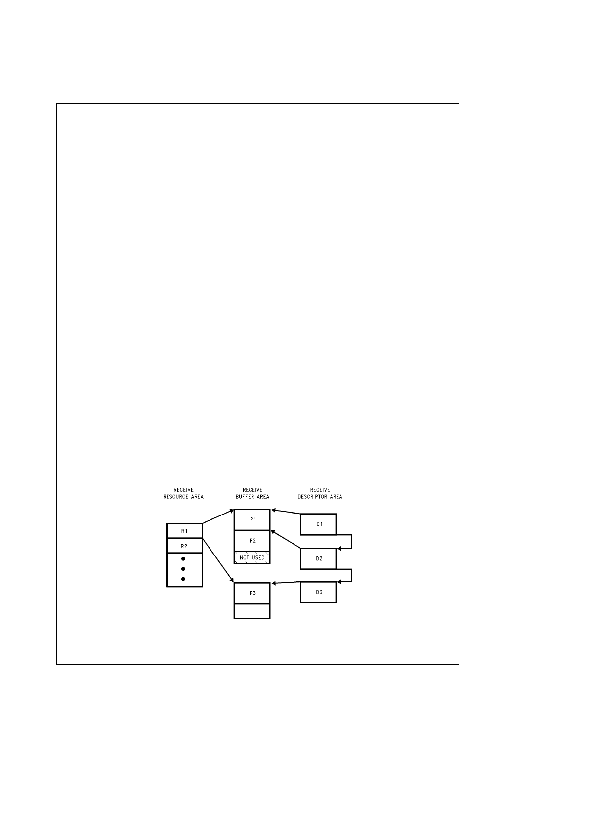
5.0 Buffer Management (Continued)
5.3 DESCRIPTOR DATA ALIGNMENT
All fields used by descriptors (RXpkt.xxx, RXrsrc.xxx, and
TXpkt.xxx) are word quantities (16-bit) and must be aligned
to word boundaries (A0
e
0) for 16-bit memory and to long
word boundaries (A1,A0
e
0,0) for 32-bit memory. The Receive Buffer Area (RBA) must also be aligned to a word
boundary in 16-bit mode and a long word boundary in 32-bit
mode. The fragments in the Transmit Buffer Area (TBA),
however, may be aligned on any arbitrary byte boundary.
5.4 RECEIVE BUFFER MANAGEMENT
The Receive Buffer Management operates on three areas in
memory into which data, status, and control information are
written during reception
(Figure 5-3)
. These three areas
must be initialized (Section 5.4.4) before enabling the receiver (setting the RXEN bit in the Command Register). The
Receive Resource Area (RRA) contains descriptors that locate Receive Buffer Areas in system memory. These descriptors are denoted by R1, R2, etc. in
Figure 5-3
. Packets
(denoted by P1, P2, etc.) can then be buffered into the corresponding RBAs. Depending on the size of each buffer
area and the size of the packet(s), multiple or single packets
are buffered into each RBA. The Receive Descriptor Area
(RDA) contains status and control information for each
packet (D1, D2, etc. in
Figure 5-3
) corresponding to each
received packet (D1 goes with P1, D2 with P2, etc.).
When a packet arrives, the address recognition logic checks
the address for a Physical, Multicast, or Broadcast match
and if the packet is accepted, the SONIC-T buffers the
packet contiguously into the selected Receive Buffer Area
(RBA). Because of the previous end-of-packet processing,
the SONIC-T assures that the complete packet is written
into a single contiguous block. When the packet ends, the
SONIC-T writes the receive status, byte count, and location
of the packet into the Receive Descriptor Area (RDA). The
SONIC-T then updates its pointers to locate the next available descriptor and checks the remaining words available in
the RBA. If sufficient space remains, the SONIC-T buffers
the next packet immediately after the previous packet. If the
current buffer is out of space the SONIC-T fetches a Resource Descriptor from the Receive Resource Area (RRA)
acquiring an additional buffer that has been previously allocated by the system.
5.4.1 Receive Resource Area (RRA)
As buffer memory is consumed by the SONIC-T for storing
data, the Receive Resource Area (RRA) provides a mechanism that allows the system to allocate additional buffer
space for the SONIC-T. The system loads this area with
Resource Descriptors that the SONIC-T, in turn, reads as its
current buffer space is used up. Each Resource Descriptor
consists of a 32-bit buffer pointer locating the starting point
of the RBA and a 32-bit word count that indicates the size of
the buffer in words (2 bytes per word). The buffer pointer
and word count are contiguously located using the format
shown in
Figure 5-4
with each component composed of
16-bit fields. The SONIC-T stores this information internally
and concatenates the corresponding fields to create 32-bit
long words for the buffer pointer and word count. Note that
in 32-bit mode the upper word (D
k
31:16l) is not used by
the SONIC-T. This area may be used for other purposes
since the SONIC-T never writes into the RRA.
The SONIC-T organizes the RRA as a circular queue for
efficient processing of descriptors. Four registers define the
RRA. The first two, the Resource Start Area (RSA) and the
Resource End Area (REA) registers, determine the starting
and ending locations of the RRA, and the other two registers update the RRA. The system adds descriptors at the
address specified by the Resource Write Pointer (RWP),
and the SONIC-T reads the next descriptor designated by
the Resource Read Pointer (RRP). The RRP is advanced 4
words in 16-bit mode (4 long words in 32-bit mode) after the
SONIC-T finishes reading the RRA and automatically wraps
around to the beginning of the RRA once the end has been
reached. When a descriptor in the RRA is read, the
RXrsc.buffÐpt0,1 is loaded into the CRBA0,1 registers and
the RXrsc.buffÐwc0,1 is loaded into the RBWC0,1 registers.
The alignment of the RRA is confined to either word or long
word boundaries, depending upon the data width mode. In
16-bit mode, the RRA must be aligned to a word boundary
(A0 is always zero) and in 32-bit mode, the RRA is aligned
to a long word boundary (A0 and A1 are always zero).
TL/F/12597– 16
FIGURE 5-3. Overview of Receive Buffer Management
http://www.national.com 26
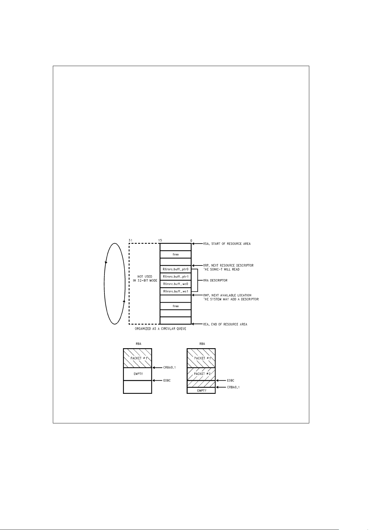
5.0 Buffer Management (Continued)
5.4.2 Receive Buffer Area (RBA)
The SONIC-T stores the actual data of a received packet in
the RBA. The RBAs are designated by the Resource Descriptors in the RRA as described above. The RXrsrc.buff
Ð
wc0,1 fields of the RRA indicate the length of the RBA.
When the SONIC-T gets an RBA from the RRA, the
RXrsrc.buffÐwc0,1 values are loaded into the Remaining
Buffer Word Count registers (RBWC0,1). These registers
keep track of how much space (in words) is left in the buffer.
When a packet is buffered in a RBA, it is buffered contiguously (the SONIC-T will not scatter a packet into multiple
buffers or fragments). Therefore, if there is not enough
space left in a RBA after buffering a packet to buffer at least
one more maximum sized packet (the maximum legal sized
packet expected to be received from the network), a new
buffer must be acquired. The End of Buffer Count (EOBC)
register is used to tell the SONIC-T the maximum packet
size that the SONIC-T will need to buffer.
5.4.2.1 End of Buffer Count (EOBC)
The EOBC is a boundary in the RBA based from the bottom
of the buffer. The value written into the EOBC is the maximum expected size (in words) of the network packet that
the SONIC-T will have to buffer. This word count creates a
line in the RBA that, when crossed, causes the SONIC-T to
fetch a new RBA resource from the RRA.
Note: The EOBC is a word count, not a byte count. Also, the value pro-
grammed into EOBC must be a double word (32-bit) quantity when
the SONIC-T is in 32-bit mode (e.g., in 32-bit mode, EOBC should be
set to 760 words, not 759 words even though the maximum size of an
IEEE 802.3 packet is 759 words for double work boundary alignment).
5.4.2.2 Buffering the Last Packet in an RBA
At the start of reception, the SONIC-T stores the packet
beginning at the Current Receive Buffer Address (CRBA0,1)
and continues until the reception is complete. Concurrent
with reception, the SONIC-T decrements the Remaining
Buffer Word Count (RBWC0,1) by one in 16-bit mode or by
two in 32-bit mode. At the end of reception, if the packet has
crossed the EOBC boundary, the SONIC-T knows that the
next packet might not fit in the RBA. This check is done by
comparing the RBWC0,1 registers with the EOBC. If
RBWC0,1 is less than the EOBC (the last packet buffered
has crossed the EOBC boundary), the SONIC-T fetches the
next resource descriptor in the RRA. If RBWC0,1 is greater
than or equal to the EOBC (the EOBC boundary has not
been crossed) the next packet reception continues at the
present location pointed to by CRBA0,1 in the same RBA.
Figure 5-5
illustrates the SONIC-T’s actions for (1)
RBWC0,1
t
EOBC and (2) RBWC0,1kEOBC. See Sec-
tion 5.4.4.4 for specific information about setting the EOBC.
Note: It is important that the EOBC boundary be ‘‘crossed.’’ In other words,
case
Ý
1in
Figure 5-5
must exist before caseÝ2 exists. If caseÝ2
occurs without case
Ý
1 having occurred first, the test for RBWC0,1
k
EOBC will not work properly and the SONIC-T will not fetch a new
buffer. The result of this will be a buffer overflow (RBAE in the Interrupt Status Register, Section 6.4.6).
TL/F/12597– 17
FIGURE 5-4. Receive Resource Area Format
TL/F/12597– 18
CaseÝ1
Case
Ý
2
(RBWC0,1
t
EOBC)
(RBWC0,1
k
EOBC)
Case
Ý
1: SONIC-T buffers next packet in same RBA.
Case
Ý
2: SONIC-T detects an exhausted RBA and will buffer the next packet in another RBA.
FIGURE 5-5. Receive Buffer Area
http://www.national.com27
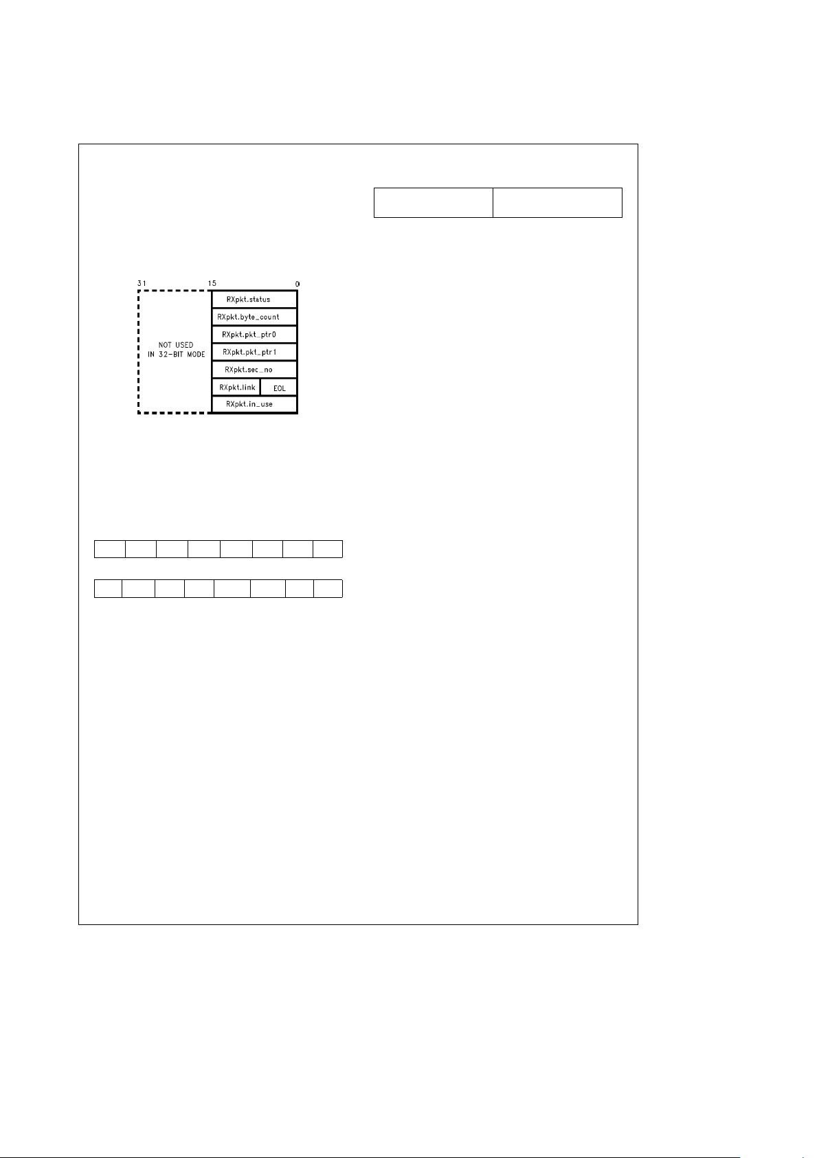
5.0 Buffer Management (Continued)
5.4.3 Receive Descriptor Area (RDA)
After the SONIC-T buffers a packet to memory, it writes 6
words of status and control information into the RDA reads
the link field to the next Receive Descriptor, and writes to
the in-use field of the current descriptor. In 32-bit mode the
upper word, D
k
31:16l, is not used. This unused area in
memory should not be used for other purposes, since the
SONIC-T may still write into these locations. Each Receive
Descriptor consists of the following sections:
(Figure 5-6)
.
TL/F/12597– 19
FIGURE 5-6. Receive Descriptor Format
receive status: indicates status of the received packet. The
SONIC-T writes the Receive Control register values into this
field.
Figure 5-7
shows the receive status format. This field
is loaded from the contents of the Receive Control register.
Note that ERR, RNT, BRD, PRO, and AMC are configuration bits and are programmed during initialization. See Section 6.4.3 for the description of the Receive Control register.
15 14 13 12 11 10 9 8
ERR RNT BRD PRO AMC LB1 LB0 MC
7654 3 2 10
BC LPKT CRS COL CRCR FAER LBK PRX
FIGURE 5-7. Receive Status Format
byte count: gives the length of the complete packet from
the start of Destination Address to the end of Frame Check
Sequence (FCS).
packet pointer: a 32-bit pointer that locates the packet in
the RBA. The SONIC-T writes the contents of the CRBA0,1
registers into this field.
sequence numbers: this field displays the contents of two
8-bit counters (modulo 256) that sequence the RBAs used
and the packets buffered. These counters assist the system
in determining when an RBA has been completely processed. The sequence numbers allow the system to tally the
packets that have been processed within a particular RBA.
There are two sequence numbers that describe a packet:
the RBA Sequence Number and the Packet Sequence
Number. When a packet is buffered to memory, the
SONIC-T maintains a single RBA Sequence Number for all
packets in an RBA and sequences the Packet Number for
succeeding packets in the RBA. When the SONIC-T uses
the next RBA, it increments the RBA Sequence Number and
clears the Packet Sequence Number. The RBA’s sequence
counter is not incremented when the Read RRA command
is issued in the Command register. The format of the Receive Sequence Numbers is shown in
Figure 5-8
. These
counters are reset during a SONIC-T hardware reset or by
writing zero to them.
15 8 7 0
RBA Sequence Number Packet Sequence Number
(Modulo 256) (Modulo 256)
FIGURE 5-8. Receive Sequence Number Format
receive link field: a 15-bit pointer (A15–A1) that locates
the next receive descriptor. The LSB of this field is the End
Of List (EOL) bit and indicates the last descriptor in the list.
(Initialized by the system.)
in-use field: this field provides a handshake between the
system and the SONIC-T to indicate the ownership of the
descriptor. When the system avails a descriptor to the
SONIC-T, it writes a non-zero value into this field. The
SONIC-T, in turn, sets this field to all ‘‘0’s’’ when it has
finished processing the descriptor. (That is, when the CRDA
register has advanced to the next receive descriptor.) Generally, the SONIC-T releases control after writing the status
and control information into the RDA. If, however, the SONIC-T has reached the last descriptor in the list, it maintains
ownership of the descriptor until the system has appended
additional descriptors to the list. The SONIC-T then relinquishes control after receiving the next packet. (See Section 5.4.6.1 for details on when the SONIC-T writes to this
field.) The receive packet descriptor format is shown in
Fig-
ure 5-6
.
5.4.4 Receive Buffer Management Initialization
The Receive Resource, Descriptor, and Buffer areas (RRA,
RDA, RBA) in memory and the appropriate SONIC-T registers must be properly initialized before the SONIC-T begins
buffering packets. This section describes the initialization
process.
5.4.4.1 Initializing The Descriptor Page
All descriptor areas (RRA, RDA, and TDA) used by the
SONIC-T reside within areas up to 32k (word) or 16k (long
word) pages. This page may be placed anywhere within the
32-bit address range by loading the upper 16 address lines
into the UTDA, URDA, and URRA registers.
5.4.4.2 Initializing The RRA
The initialization of the RRA consists of loading the four
SONIC-T RRA registers and writing the resource descriptor
information to memory.
The RRA registers are loaded with the following values.
Resource Start Area (RSA) register: The RSA is loaded
with the lower 16-bit address of the beginning of the RRA.
Resource End Area (REA) register: The REA is loaded
with the lower 16-bit address of the end of the RRA. The
end of the RRA is defined as the address of the last
RXrsrc.ptr0 field in the RRA plus 4 words in 16-bit mode or 4
long words in 32-bit mode
(Figure 5-4)
.
Resource Read Pointer (RRP) register: The RRP is loaded with the lower 16-bit address of the first resource descriptor the SONIC-T reads.
Resource Write Pointer (RWP) register: The RWP is loaded with the lower 16-bit address of the next vacant location
where a resource descriptor will be placed by the system.
Note: The RWP register must only point to either (1) the RXrsrc.ptr0 field of
one of the RRA Descriptors, (2) the memory address that the RSA
points to (the start of the RRA), or (3) the memory address that the
REA points to (the end of the RRA). When the RWP
e
RRP comparison is made, it is performed after the complete RRA descriptor has
been read and not during the fetch. Failure to set the RWP to any of
the above values prevents the RWP
e
RRP comparison from ever
becoming true.
http://www.national.com 28
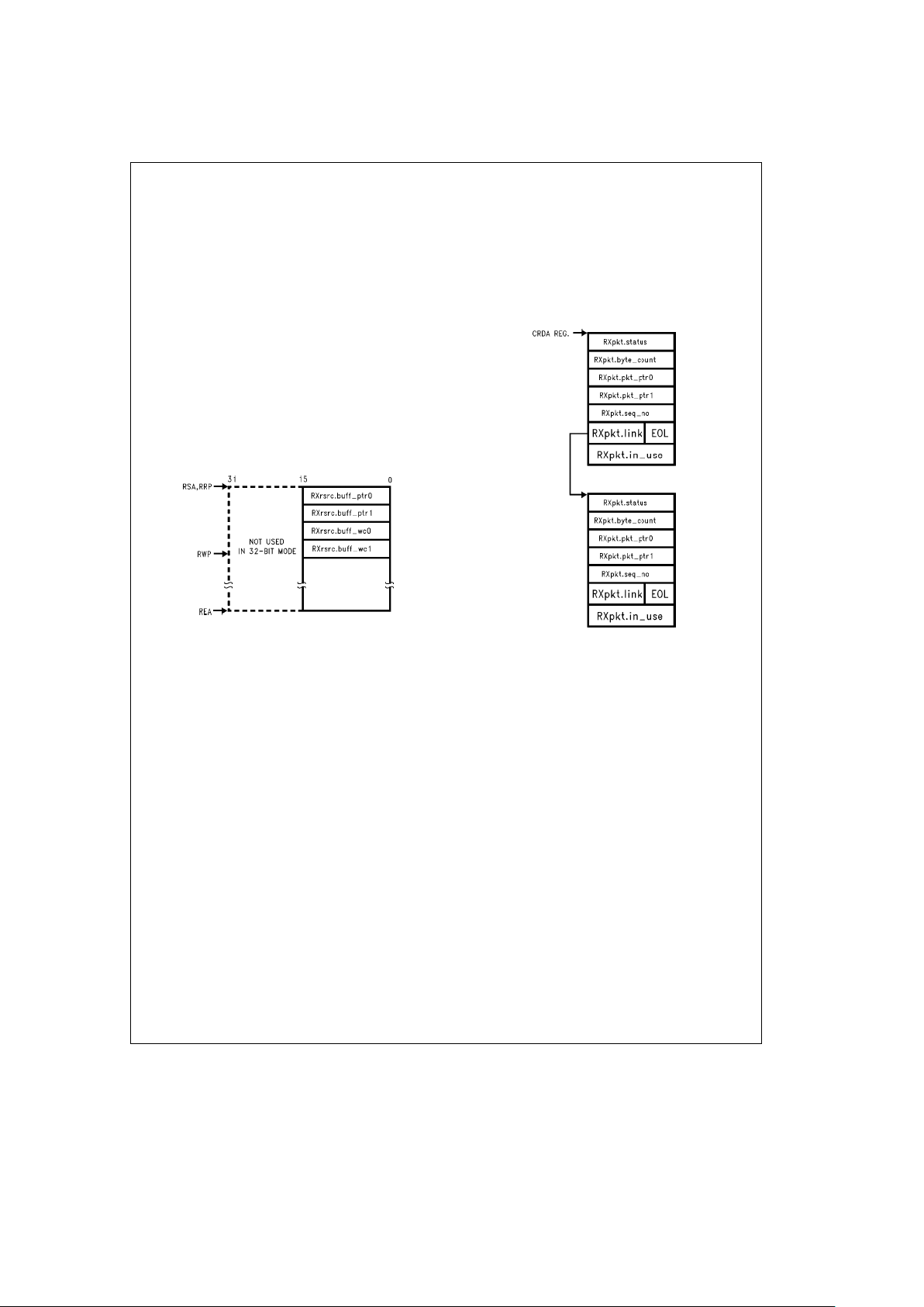
5.0 Buffer Management (Continued)
All RRA registers are concatenated with the URRA register
for generating the full 32-bit address.
The resource descriptors that the system writes to the RRA
consists of four fields: (1) RXrsrc.buffÐptr0, (2)
RXrsrc.buffÐptr1, (3) RXrsrc.buffÐwc0, and (4)
RXrsrc.buffÐwc1. The fields must be contiguous (they cannot straddle the end points) and are written in the order
shown in
Figure 5-9
. The ‘‘0’’ and ‘‘1’’ in the descriptors
denote the least and most significant portions for the Buffer
Pointer and Word Count. The first two fields supply the
32-bit starting location of the Receive Buffer Area (RBA),
and the second two define the number of 16-bit words that
the RBA occupies.
Note that two restrictions apply to the Buffer Pointer and
Word Count. First, in 32-bit mode, since the SONIC-T always writes long words, an even count must be written to
RXrsrc.buffÐwc0. Second, the Buffer Pointer must either
be pointing to a word boundary in 16-bit mode (A0
e
0) or a
long word boundary in 32-bit mode (A0,A1
e
0,0). Note also
that the descriptors must be properly aligned in the RRA as
discussed in Section 5.3.
TL/F/12597– 20
FIGURE 5-9. RRA Initialization
After configuring the RRA, the RRA Read command (setting
RRRA bit in the Command register) may be given. This
command causes the SONIC-T to read the RRA descriptor
in a single block operation, and load the following registers
(see Section 6.2 for register mnemonics):
CRBA0 register
w
RXrsrc.buffÐptr0
CRBA1 register
w
RXrsrc.buffÐptr1
RBWC0 register
w
RXrsrc.buffÐwc0
RBWC1 register
w
RXrsrc.buffÐwc1
When the command has completed, the RRRA bit in the
Command register is reset to ‘‘0’’. Generally this command
is only issued during initialization. At all other times, the RRA
is automatically read as the SONIC-T finishes using an RBA.
5.4.4.3 Initializing The RDA
To accept multiple packets from the network, the receive
packet descriptors must be linked together via the
RXpkt.link fields. Each link field must be written with a 15-bit
(A15–A1) pointer to locate the beginning of the next descriptor in the list. The LSB of the RXpkt.link field is the End
Of List (EOL) bit and is used to indicate the end of the
descriptor list. EOL
e
1 for the last descriptor and EOLe0
for the first or middle descriptors. The RXpkt.inÐuse field
indicates whether the descriptor is owned by the SONIC-T.
The system writes a non-zero value to this field when the
descriptor is available, and the SONIC-T writes all ‘‘0’s’’
when it finishes using the descriptor. At startup, the Current
Receive Descriptor Address (CRDA) register must be loaded with the address of the first RXpkt.status field in order for
the SONIC-T to begin receive processing at the first descriptor. An example of two descriptors linked together is
shown in
Figure 5-10
. The fields initialized by the system are
displayed in bold type. The other fields are written by the
SONIC-T after a packet is accepted. The RXpkt.inÐuse
field is first written by the system, and then by the SONIC-T.
Note that the descriptors must be aligned properly as discussed in Section 5.3. Also note that the URDA register is
concatenated with the CRDA register to generate the full
32-bit address.
TL/F/12597– 21
FIGURE 5-10. RDA Initialization Example
5.4.4.4 Initializing the Lower Boundary of the RBA
A ‘‘false bottom’’ is set in the RBA by loading the End Of
Buffer Count (EOBC) register with a value equal to the maximum size packet in words (16 bits) that may be received.
This creates a lower boundary in the RBA. Whenever the
Remaining Buffer Word Count (RBWC0,1) registers decrement below the EOBC register, the SONIC-T buffers the
next packet into another RBA. This also guarantees that a
packet is always contiguously buffered into a single Receive
Buffer Area (RBA). The SONIC-T does not buffer a packet
into multiple RBAs. Note that in 32-bit mode, the SONIC-T
holds the LSB always low so that it properly compares with
the RBWC0,1 registers.
After a hardware reset, the EOBC reset, the EOBC register
is automatically initialized to 2F8h (760 words or 1520
bytes). For 32-bit applications this is the suggested value for
EOBC. EOBC defaults to 760 words (1520 bytes) instead of
759 words (1518 bytes) because 1518 is not a double word
(32-bit) boundary (see Section 5.4.2.1). If the SONIC-T is
used in 16-bit mode, then EOBC should be set to 759 words
(1518 bytes) because 1518 is a word (16-bit) boundary.
Sometimes it may be desired to buffer a single packet per
RBA. When doing this, it is important to set EOBC and the
buffer size correctly. The suggested practice is to set EOBC
to a value that is at least 4 bytes, in 32-bit mode, or 2 bytes,
in 16-bit mode, less than the buffer size. An example of this
for 32-bit mode is to set EOBC to 760 words (1520 bytes)
http://www.national.com29
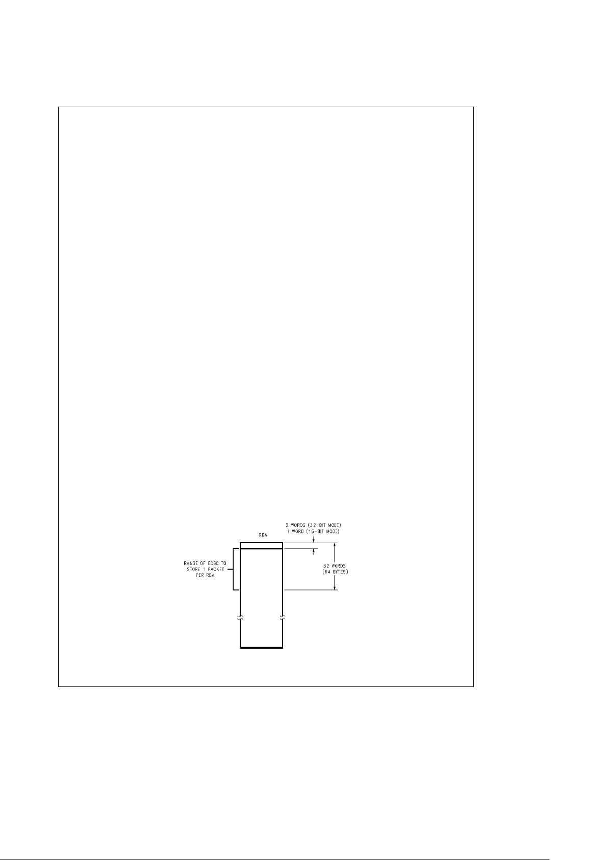
5.0 Buffer Management (Continued)
and the buffer size to 762 words (1524 bytes). A similar
example for 16-bit mode would be EOBC
e
759 words
(1518 bytes) and the buffer size set to 760 words (1520
bytes). The buffer can be any size, but as long as the EOBC
is 2 words, for 32-bit mode, or 1 word, for 16-bit mode, less
than the buffer size, only one packet will be buffered in that
RBA.
Note 1: It is possible to filter out most oversized packets by setting the buff-
er size to 760 words (1520 bytes) in 32-bit mode or 759 words (1518
bytes) in 16-bit mode. EOBC would be set to 758 words (1516
bytes) for both cases. With this configuration, any packet over 1520
bytes, in 32-bit mode, or 1518 bytes, in 16-bit mode, will not be
completely buffered because the packet will overflow the buffer.
When a packet overflow occurs, a Receive Buffer Area Exceeded
interrupt (RBAE in the Interrupt Status Register, Section 6.4.6) will
occur.
Note 2: When buffering one packet per buffer, it is suggested that the val-
ues in Note 1 above be used. Since the minimum legal sized Ethernet packet is 64 bytes, however, it is possible to set EOBC as much
as 64 bytes less than the buffer size and still end up with one packet
per buffer.
Figure 5-11
shows this ‘‘range.’’
5.4.5 Beginning Of Reception
At the beginning of reception, the SONIC-T checks its internally stored EOL bit from the previous RXpkt.link field for a
‘‘1’’. If the SONIC-T finds EOL
e
1, it recognizes that after
the previous reception, there were no more remaining receive packet descriptors. It re-reads the same RXpkt.link
field to check if the system has updated this field since the
last reception. If the SONIC-T still finds EOL
e
1, reception
ceases. (See Section 5.5 for adding descriptors to the list.)
Otherwise, the SONIC-T begins storing the packet in the
RBA starting at the Current Receive Buffer Address
(CRBA0,1) registers and continues until the packet has
completed. Concurrent with the packet reception, the Remaining Buffer Word Count (RBWC0,1) registers are decremented after each word is written to memory. This register
determines the remaining words in the RBA at the end of
reception.
5.4.6 End Of Packet Processing
At the end of a reception, the SONIC-T enters its end of
packet processing sequence to determine whether to accept or reject the packet based on receive errors and packet size. At the end of reception the SONIC-T enters one of
the following two sequences:
Ð Successful reception sequence
Ð Buffer recovery for runt packets or packets with errors
5.4.6.1 Successful Reception
If the SONIC-T accepts the packet, it first writes 5 words of
descriptor information in the RDA beginning at the address
pointed to by the Current Receive Descriptor Address
(CRDA) register. It then reads the RXpkt.link field to advance the CRDA register to the next receive descriptor. The
SONIC-T also checks the EOL bit for a ‘‘1’’ in this field. If
EOL
e
1, no more descriptors are available for the SONIC-T.
The SONIC-T recovers the address of the current RXpkt.link
field (from a temporary register) and generates a ‘‘Receive
Descriptors Exhausted’’ indication in the Interrupt Status
register. (See Section 5.4.7 on how to add descriptors.) The
SONIC-T maintains ownership of the descriptor by
not
writ-
ing to the RXpkt.inÐuse field. Otherwise, if EOL
e
0, the
SONIC-T advances the CRDA register to the next descriptor
and resets the RXpkt.inÐuse field to all ‘‘0’s’’.
The SONIC-T accesses the complete 7 word RDA descriptor in a single block operation.
The SONIC-T also checks if there is remaining space in the
RBA. The SONIC-T compares the Remaining Buffer Word
Count (RBWC0,1) registers with the static End Of Buffer
Count (EOBC). If the RBWC is less than the EOBC, a maximum sized packet will no longer fit in the remaining space in
the RBA; hence, the SONIC-T fetches a resource descriptor
from the RRA and loads its registers with the pointer and
word count of the next available RBA.
5.4.6.2 Buffer Recovery For Runt Packets Or
Packets With Errors
If a runt packet (less than 64 bytes) or packet with errors
arrives and the Receive Control register has been configured to not accept these packets, the SONIC-T recovers its
pointers back to the original positions. The CRBA0,1 registers are not advanced and the RBWC0,1 registers are not
decremented. The SONIC-T recovers its pointers by maintaining a copy of the buffer address in the Temporary Receive Buffer Address registers (TRBA0,1). The SONIC-T recovers the value in the RBWC0,1 registers from the Temporary Buffer Word Count registers (TBWC0,1).
5.4.7 Overflow Conditions
When an overflow condition occurs, the SONIC-T halts its
DMA operations to prevent writing into unauthorized memory. The SONIC-T uses the Interrupt Status register (ISR) to
indicate three possible overflow conditions that can occur
TL/F/12597– 22
Range of EOBCe(RXrsrc.wc0,1b2 to RXrsrc.wc0,1b32)
FIGURE 5-11. Setting EOBC for Single Packet RBA
http://www.national.com 30
 Loading...