

NC400-6 Counter
ELECTRONIC PROGRAMMABLE COUNTER – INSTRUCTIONS MANUAL – V1.2x A
SAFETY ALARMS
The following symbols appear in the device and throughout this
manual to call the user’s attention as to important information related
to safety and device use.
CAUTION:
Read manual carefully before
installing and operating the device
All safety recommendations must be followed as to warrant the
individual’s safety and prevent damage to the instrument or system. If
the instrument is used in another way other than that specified in this
manual, the equipment safety protections may not work properly.
Over Temperature Protection
When a system is designed, it is fundamental that one considers the
consequence of any failure in any component of such system. In
temperature control application, danger is even higher when heating
remains constantly on. In applications where physical damage or
device destruction may occur, the installation of an independent
protection device is recommended, which has its own temperature
sensor and can turn off the heating circuit in case of over heating. Note
that the counter output relays of NC400-6 do not offer protection to all
failure conditions.
CAUTION OR DANGER:
Risk of electrical shocks
DESCRIPTION
The NC400-6 counter and its configuration parameters are divided in
the following blocks:
• Inputs
• Main counter
• Batch counter
Each of these blocks has its own set of configuration parameters,
which together determine how the device works. A summary of the
operation of each block is presented below as well as their
parameters.
INPUTS
NC400-6 has three inputs that can be configured to read contacts,
NPN sensors, PNP sensors or voltage pulse connections. All inputs
must receive the same type of input signal. Functions of each input
are:
COUNT1: Main counting input
HOLD/COUNT2: Input to hold counting or second counting input. The
RESET: Input for external reset of counters and/or outputs.
Man 5001392
• Totalizador counter
• OUT1
• OUT2
second counting input is required when the NC4006 counter increases or decreases actions are
determined by an external signal (quadrature
signals, for example).
INTRODUCTION
NC400-6 is an advanced 6-digit counter that also performs batch and
totalizer counting operations. It has two outputs with independent and
configurable presets that can be triggered based on counting, batch
or totalization values. Its 2 outputs allow for an independent timed
triggering.
The counting input can be configured to read dry-contact, voltage
pulse, NPN our PNP sensor connections. Sensors may be powered
by an internal power supply.
Counting mode can be configured as progressive, regressive,
quadrature, ADD or SUB. Several reset modes — automatic or
manual — can be configured. Manual reset can be generated by a
digital input or key from the front panel.
The following configuration parameters are directly related to the
operation of inputs:
SEnS.tY
SEnS.tY
SEnS.tYSEnS.tY
Coun.tY
Coun.tY
Coun.tYCoun.tY
Coun.UP
Coun.UP
Coun.UPCoun.UP
MAIN COUNTER
It counts pulses from inputs, showing the value in the display after
multiplying it by a configurable scaling factor. Manual or automatic
reset. Two Set points can be defined (presets); when they are
reached they produce configurable actions (enable output, increment
batch counter, reset counter etc.) The following configuration
parameters are directly related to the main counter operation.
FActor
FActor
FActorFActor
SP1 C
SP1 C
SP1 CSP1 C
SP2 C
SP2 C
SP2 CSP2 C
OPt.SP.C
OPt.SP.C
OPt.SP.COPt.SP.C
OFF.C
OFF.C
OFF.COFF.C
rES.C
rES.C
rES.CrES.C
Selection of type of signal (contact, pulse,
NPN, PNP).
Selection of counting speed (slow or fast).
Progressive or regressive counting choice
and use of COUNT2 input.
Factor that multiplies the number of input
pulses (0.00001
0.00001 to 9.99999
0.000010.00001
Set point 1 for the main counter.
Set point 2 for the main counter.
Condition for Set point 1 reached (main
counter higher or lower than Set point 1).
Initial value (Offset) for main counter.
Reset options in the main counter (input,
key, Set point, output, etc.).
9.99999).
9.999999.99999
NOVUS AUTOMATION 1/8
Contador Eletrônico NC400-6
BATCH COUNTER
Counts the number of times that Set point 2 for the main counter was
reached, with manual or automatic reset. When its Set point is
exceeded (greater than or equals to) results in configurable actions
(enable output or increment totalizer counter). It is always a
progressive counter. The following configuration parameters are
directly related to the batch counter operation.
SP bAt
SP bAt
SP bAtSP bAt
OFF.bAt
OFF.bAt
OFF.bAtOFF.bAt
rES.bAt
rES.bAt
rES.bAtrES.bAt
Batch counter Set point.
Initial value (Offset) for the batch counter.
Reset options for the batch counter (input,
key, Set point, output, etc.).
TOTALIZER COUNTER
Totalizes the main counter or the number of times that the batch
counter Set point was reached, with manual or automatic reset.
When its Set point is reached (greater than or equals to) it can
activate an output. The following configuration parameters are
directly related to the totalizer operation.
Opt.tot
Opt.tot
Opt.totOpt.tot
Totalizer counting option (input pulse or
batch)
SP tot
SP tot
SP totSP tot
OFF.t
OFF.t
OFF.tOFF.t
rES.tot
rES.tot
rES.totrES.tot
Totalizer Set point.
Initial value (Offset) for the totalizer.
Reset options for the totalizer (input, key,
Set point, output, etc.).
OUT1
This output is always associated to the main counter, and it is
activated when Set point 1 is reached, and disabled with time,
reset, Set point 1 or when OUT2 is enabled. The following
configuration parameters are directly related to the OUT1 operation.
Out1.t
Out1.t
Out1.tOut1.t
Time to deactivate OUT1 (0.00
0.00 to 9999.99
9999.99
0.000.00
9999.999999.99
s).
Out1.E
Out1.E
Out1.EOut1.E
Turn-off options of OUT1 (time, OUT2,
reset, Set point 2).
Out1.OP
Out1.OP
Out1.OPOut1.OP
Freeze counting while OUT1 is activated
(yes, no).
Out1.c
Out1.c
Out1.cOut1.c
OUT1 normal state open or closed.
OUT2
This output can be activated by Set point 2 of the main counter, by
the batch counter Set point or by the totalizer Set point. It can be
deactivated by time, reset, activation of OUT1 or Set point that
activated it. The following configuration parameters are directly
related to the OUT2 operation.
Out2.SE
Out2.SE
Out2.SEOut2.SE
OUT2 activation options (Set point 2, batches
or totalizer).
Out2.t
Out2.t
Out2.tOut2.t
Time to deactivate OUT2 (0.00
0.00 to 9999.99
9999.99
0.000.00
9999.999999.99
s).
Out2.E
Out2.E
Out2.EOut2.E
Turn-off options of OUT2 (time, OUT1,
reset).
Out2.OP
Out2.OP
Out2.OPOut2.OP
Freeze counting while OUT2 is activated
(yes, no).
Out2.c
Out2.c
Out2.cOut2.c
OUT2 normal mode open or closed.
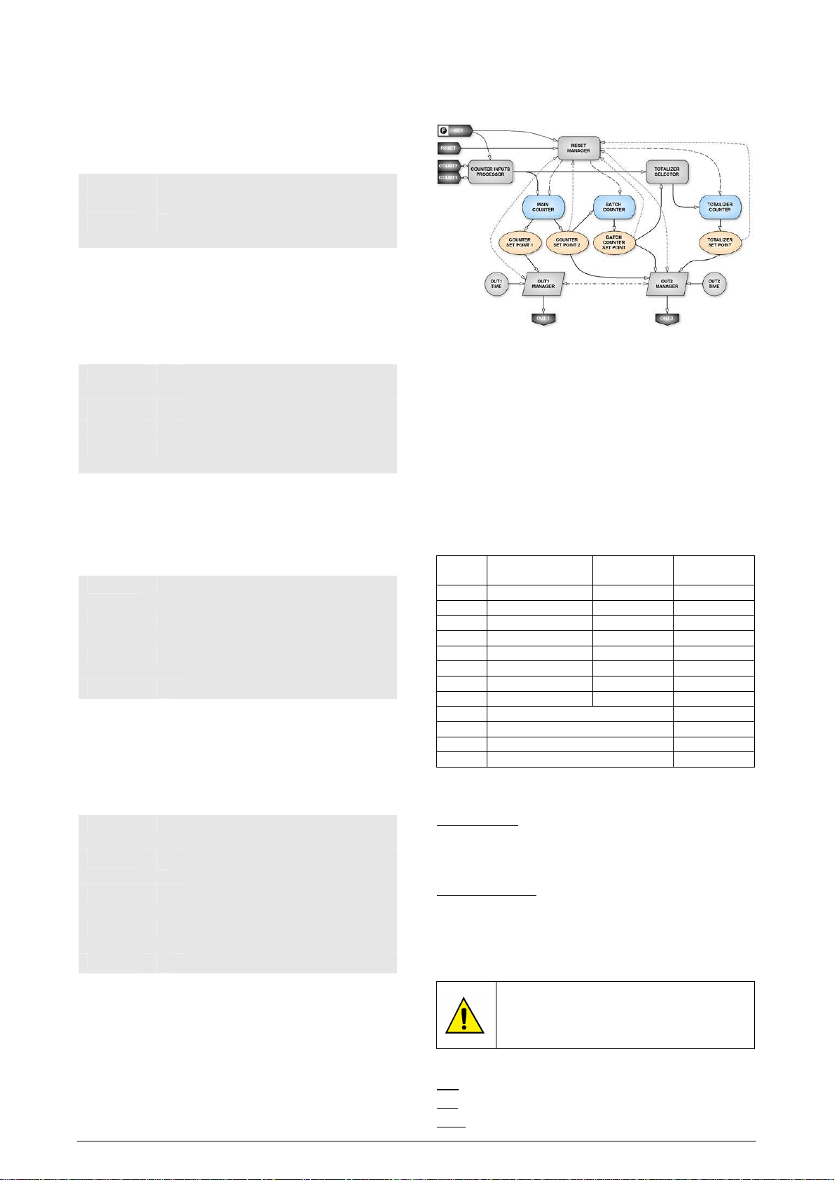
BLOCK DIAGRAM
Figure 1 illustrates associations among features and resources of
NC400-6:
Figure 1 – Diagram with features and resoucers of NC400-6
COUNTING MODES
The Coun.tY
Coun.tY parameter selects the counting mode as slow or fast.
Coun.tYCoun.tY
In the slow counting mode, a filter is applied to the counting signals,
limiting the maximum pulse frequency, which is necessary to count
the number of activations of electromechanical contacts. In the fast
counting mode, NC400-6 operates up to the maximum frequency
specified for the input signal. The frequency limits for each mode are
defined in Item 5.
The Coun.UP
Coun.UP parameter defines the main counting direction (UP or
Coun.UPCoun.UP
DOWN) and the function of each input. Table 1 shows options for
this parameter.
Code
0000
1111
4444
5555
6666
7777
8888
9999
12
12
1212
13
13
1313
14
14
1414
15
15
1515
Table 1 – Counting modes that can be selected with the Coun.UP
COUNT2/HOLD
Input
COUNT1 Input Main direction
HOLD SUB DOWN
HOLD ADD UP
SUB SUB DOWN
SUB ADD UP
ADD SUB DOWN
ADD ADD UP
Select ADD SUB or ADD DOWN
Select SUB ADD or SUB UP
QUADRATURE DOWN
QUADRATURE UP
QUADRATURE 2x DOWN
QUADRATURE 2x UP
Coun.UP parameter.
Coun.UPCoun.UP
The main counting direction affects the main counter:
Main direction UP: Main counter count upstream, starting from
the Offset value defined (usually zero).
Actions can be programmed to take place
in Set point 1 and 2 values.
Main direction DOWN: The main counter count downstream,
starting from the Set point 2 value (SP2C
SP2C).
SP2CSP2C
The action programmed for this Set point
will take place when the counter reaches
the programmed Offset value.
The totalizer direction is always up.
You can select functions for COUNT1 and COUNT2/HOLD inputs:
ADD: Progressive counting input.
SUB: Regressive counting input.
Operation descriptions in this manual consider that
the NC400-6 counter is operating in the UP direction.
To operate in DOWN direction, refer to the
explanation above.
HOLD: Stops the counting input for COUNT1.
NOVUS AUTOMATION
2
Contador Eletrônico NC400-6
Select ADD/SUB: COUNT2 input defines if COUNT1 input is
progressive or regressive.
QUADRATURE: Bidirectional counting mode that uses two
counting inputs to determine if counting is
progressive or regressive. In this counting
mode, the Coun.tY
Coun.tY parameter is ignored
Coun.tYCoun.tY
and the counting mode is always fast.
QUADRATURE 2X: The same as the QUADRATURE mode,
but it counts twice as fast, increasing
resolution. In this counting mode, the
Coun.tY
Coun.tY parameter is ignored and the
Coun.tYCoun.tY
counting mode is always fast.
The counter is incremented or decremented whenever the voltage
level in the counting inputs increases (rising edge) except in the fast
counting mode (Coun.tY
Coun.tY = 1111) in COUNT1 input.
Coun.tYCoun.tY
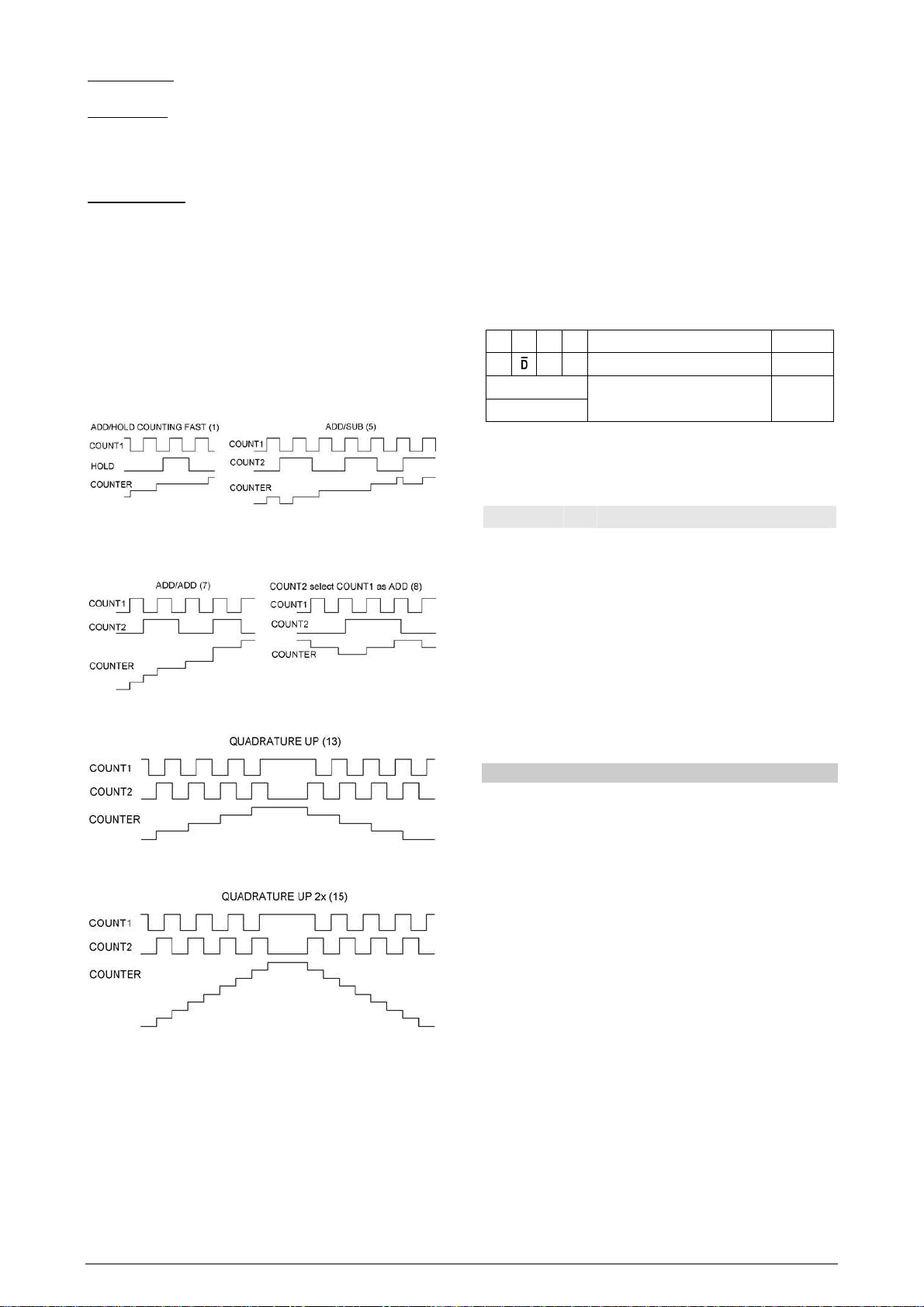
The most representative counting modes are shown in Figures 2 to
5. Low and High levels in the following figures correspond to voltage
levels in these inputs with PNP sensor or Voltage pulse. For the case
of NPN sensors or dry contact, signals will be reversed.
Figure 2 – Counting modes 1 and 5
Figure 3 – Counting modes 7 and 8
FEATURES
• Signals compliant with the RS-485 standard. MODBUS (RTU)
protocol. 2 wire connection between 1 master and up to 31 (able
to address up to 247) instruments in bus topology.
Communication signals are electrically isolated from the rest of
the device;
• Maximum connection distance: 1000 meters;
• NC400-6 disconnection time: Maximum 2 ms after the last byte;
• Fixed communication speed (Baud Rate): 9600 bps;
• Number of data bits: 8, no parity. Number of stop bits: 1;
• Transmission onset and response time: maximum of 100 ms
after command.
RS-485 signals are:
D1 D D + B
D0
D - A
C
GND
CONFIGURATION OF SERIAL COMMUNICATION PARAMATERS
Bidirectional data line. Terminal 16
Reserved bidirectional data line. Terminal 17
Optimal connection that enhances
the communication performance.
Parameter that must be configured when the serial communication
used:
Addres
Addres
AddresAddres
OVERFLOW AND UNDERFLOW
NC400-6 counter communication adress.
If the counter is at 0000 and it receives a pulse to decrement, the
counter will show 999.999
that the counter rolls to 999.999
999.999 and turn the OVFL flag on. This means
999.999999.999
999.999. If it increments beyond this, it will
999.999999.999
roll back to 0000, clearing OVFL flag.
On a similar way, when the counter is at 999.999
999.999 and it is
999.999999.999
increased, it will roll to 0000 and turn the OVFL flag on. When it
decreases again below 0000, it will turn the flag off and roll back to
999.999
999.999.
999.999999.999
Note: The setpoints and output control have no effect while OVFL
flag is on, except those who are cleared by time.
Terminal 18
Figure 4 – Counting mode 13 (quadrature)
Figure 5 – Counting mode 15 (quadrature 2x)
SERIAL COMUNICATION (OPTIONAL)
Optionally, NC400-6 can be deliverd with an assynchronous masterslave serial communication interface RS-485 to communicate with a
supervisor computer (master). The counter is always the slave.
Communication always start with the master, which sends a
command to the slave address with whom it wants to communicate.
The addressed slave undertakes the command and sends the
response to the master. NC400-6 also accepts broadcast
commands.
INSTALATION
PANEL MOUNT
NC400-6 must be installed in a papel. To install, follow the steps
below:
1. Make a panel cutout of 45.5 x 45.5 mm;
2. Remove the clips from NC400-6;
3. Insert NC400-6 in the frontal panel cutout;
4. Replace clips in NC400-6 and press them tightly to clamp the
counter to the panel.
INSTALLATION RECOMMENDATIONS
• Input signal wires must be installed in grounded conduits and
away from power or contactor wires+
• Instruments must be powered only by an exclusive power
supply.
• System failure should always be taken into account when
designing a control panel to avoid irreversible damage to
equipment or people. The output internal relay does not warrant
total protection.
• Installing RC filters (47 Ohms and 100 nF, serial) is strongly
recommended at contactor coils or any other inductors.
NOVUS AUTOMATION
3

Contador Eletrônico NC400-6
ELECTRICAL CONNECTIONS
You can remove the internal part of the device from its case
without removing connections. Signals are distributed in the rear
panel as shown in Figure 6.
Figure 6 – Electrical connections of NC400-6
POWER SUPPLY - POWER
Before making the power supply connection (terminals 1 and 2),
check the power voltage specified in the NC400-6 lateral
identification label. It is recommended to install electrical safety
devices.
Installation must have a switch that is able to turn off
all electrical current leads. This device must be
mounted close to the NC400-6, with easy operator
access and identified as a device that disconnects
the instrument.
Input, output and power connections, according to
Figure 6.
OUTPUTS – OUT1 / OUT2
OUT 2 (terminals 3 and 4) is always a relay. OUT1 (terminals 5 and
6) can be a relay or voltage pulse. See Item 6 – Identification to
determinate the OUT1 type.
Connect outputs respecting the specified capacity for voltage and
current. Check polarity for pulse output.
Counting and command inputs – COUNT1 / COUNT2 / RESET
COUNT1, COUNT2 and RESET inputs accept connections of NPN
or PNP sensors, dry-contact or voltage pulse. The type of signal is
configured through the SEnS.tY
SEnS.tY parameter, and all inputs must be
SEnS.tYSEnS.tY
the same type.
Figures 7a, 7b and 7c illustrates connections of those signals to the
COUNT1 input. The same connection scheme applies to the other
inputs.
NPN or PNP sensors
Figure 7a – Connections to the NC400-6 inputs
Voltage pulse
Figure 7c – Connections to the NC400-6 inputs
AUXILIARY SUPPLY OUTPUT
NC400-6 has an auxiliary power supply output for external sensors
(terminals 7 and 8). Check polarity and current limits before
connecting external devices to the auxiliary supply. Inputs 8 and 9
are internally connected (not isolated)
CONFIGURATION
The proper operation of NC400-6 depends on the proper
configuration of all parameters. Read the manual carefully and
thoroughly before using the equipment.
KEYBOARD AND DISPLAY OPERATION
All configuration operations are performed through the front panel
display and keyboard. The following are the panel elements and how
to operate them.
RUN: It is activated when the display shows
the main counter value.
PM: It is activated when the display shows
the batch counter value.
TOT: It is activated when the display shows
the totalizer value.
OUT1: It is activated whenever OUT1 is on.
OUT2: It is activated whenever OUT2 is on.
HOLD: It is activated whenever the counting
input is on hold (because of Hold input
activation, programmed input for key
or configuration in Out1.OP
Out2.OP
Out2.OP).
Out2.OPOut2.OP
COM: Flashes whenever NC400-6 is exchanging data
through the communication interface (optional).
OVFL: When the display shows the value of one of the 3
counters, it means that the counter displayed is in
overflow (counting over 999999 or below 0).
MIN: When the display shows the value of the main counter
or totalizer, it means that the counter displayed is with
a value below the offset (OFF.C
MAX: When the display shows the value of the main counter,
the batch counter or totalizer, it means that the counter
displayed is with a value above SP2C
SPtot
SPtot, respectively.
SPtotSPtot
Navigation key to access parameters.
Key to increment NC400-6 parameters.
Navigation key to access different digits in NC400-6.
User-programmed key (see parameter F.Fun
OFF.C or OFF.t
OFF.COFF.C
OFF.t).
OFF.tOFF.t
SP2C, SPbAt
SP2CSP2C
Out1.OP or
Out1.OPOut1.OP
SPbAt or
SPbAtSPbAt
F.Funcccc).
F.FunF.Fun
Dry contact
Operation and configuration parameters of NC400-6 are grouped in 4
Cycles:
CYCLE ACCESS
Figure 7b – Connections to the NC400-6 inputs
Count Free
Set points (presets) Timed. Can be password-protected
Configuration Timed. Can be password-protected
Hardware setup Time and password-protected
NOVUS AUTOMATION
4

Contador Eletrônico NC400-6
ffect
When the device is powered, display shows the counting cycle and the
main counter value. Press to switch to the batch counter and
totalizer. Press to select the decimal point position for the main
counter and totalizer (the batch counter does not use decimal points).
To access cycles with timed access, press and hold for 2 seconds,
which will provide access to the following upper cycle. Press and hold
to access the following upper cycles.
In any cycle you can use to go to the next parameter. Press
to change a parameter. Press to increment the flashing digit and
to go to the next digit. In screens with decimal point configuration,
it can be configured after passing through all the other digits. The
parameter changed is saved in nonvolatile memory when is
pressed.
Keys to access, change and save configuration parameters
To change parameters For 2 seconds to change cycle
Blink the most significant
digit
To change the blinking digit
To increment the blinking digit
To save and change parameter
again
PASSWORD
Depending on the protection level defined in Prot
Prot, the PASS
ProtProt
PASS screen
PASSPASS
can be displayed before access to Set points, Configuration or
Hardware setup Cycles. If the wrong password is informed, all
parameters will be protected against changes, and could only be
viewed. Insert the right password to change parameters for a cycle.
Default password is 1111
1111, and can be changed in Pass.C
11111111
Pass.C
Pass.CPass.C
parameter.
In case you enter the wrong password 5 consecutive
times, a new attempt will only be allowed after 10
minutes.
In case you have changed or forgotten the password,
see item “Master Password” to check how to
determine a master password for your device.
MASTER PASSWORD
The master password allows user to define a new password for the
NC400-6. It is the first four digits of the serial number.
Ex.: The master password for device with serial number 87123465 is:
8 7 1 2
How to use the master password:
1- Enter the master password value at PasS
2- Go to PAS.c
PAS.c parameter and enter a new password.
PAS.cPAS.c
PasS.
PasSPasS
3- Now you can use this new password.
COUNTING CYCLE
Indication of MAIN COUNTER value
Press to change the decimal point position
Indication of BATCH COUNTER value
Indication of TOTALIZER COUNTER value
Press to change the decimal point position.
SET POINTS CYCLE
SP1 C
SP1 C
SP1 CSP1 C
Set Point 1 -
Counter
Sp2 c
Sp2 c
Sp2 cSp2 c
Set Point 2 -
Counter
Set point 1 value of the main counter.
Values range from 0.00000
configurable decimal point.
Set point 2 value of the main counter.
Values range from 0.00000
configurable decimal point.
0.00000 to 999999
0.000000.00000
0.00000 to 999999
0.000000.00000
999999 with
999999999999
999999 with
999999999999
SP bat
SP bat
SP batSP bat
Set Point – Batch
SP tot
SP tot
SP totSP tot
Set Point -
Totalizer
Batch counter Set point value.
Values range from 0000 to 999999
Set point 1 value of the totalizer counter.
Values range from 0.00000
configurable decimal point.
CONFIGURATION CYCLE
Duration in seconds of OUT1 pulse. Configurable
from 0.00
0.00 to 9999.99
Out1.t
Out1.t
Out1.tOut1.t
Out1 Time
Out2.t
Out2.t
Out2.tOut2.t
Out2 Time
Off.c
Off.c
Off.cOff.c
Offset - Counter
Off.bat
Off.bat
Off.batOff.bat
Offset - Batch
Off.tot
Off.tot
Off.totOff.tot
Offset - Totalizer
f.func
f.func
f.funcf.func
F Key Function
Opt.tot
Opt.tot
Opt.totOpt.tot
Options - Totalizer
0.000.00
If OUT1 is configured to turn off after a period of time
(Out1.E
Out1.E) parameter) and the programmed time is 0000,
Out1.EOut1.E
OUT1 will not be enabled.
Duration in seconds of OUT2 pulse. Configurable
from 0.00
0.00 to 9999.99
0.000.00
If OUT2 is configured to turn off after a period of time
(Out2.E
Out2.E parameter) and the programmed time is 0000,
Out2.EOut2.E
OUT2 will not be enabled.
Value assigned to the main counter when it is started
(reset).
May vary from 0000 to 999999
Value assigned to the batch counter when it is
started (reset).
May vary from 0000 to 999999
Value assigned to the totalizer counter as soon as it
is started (reset).
May vary from 0000 to 999999
Function programmed to key.
0000: No function associated.
1111: Holds input countings. Press once to hold
the counters. Press the key again to return
counting.
2222: Reset of counters configured to reset with
key. Leaves Hold state.
3333: Output Reset.
4444: Reset of counters configured to reset with
key. Outputs reset. Leaves Hold state.
Define work modes for the totalizer.
1111: Totalizes pulses applied to the main counter
0000: Counts how many times the batch counter
reached SPbAt
Condition for OUT1 to turn off.
out1.e
out1.e
out1.eout1.e
Out1 – End
999999.
999999999999
0.00000 to 999999
0.000000.00000
9999.99s.
9999.999999.99
9999.99s.
9999.999999.99
999999.
999999999999
999999.
999999999999
999999.
999999999999
SPbAt.
SPbAtSPbAt
0000: Set point 1 does not turn off
OUT1.
1111: Turns off when (see parameter
opt.sp.c
opt.sp.c). For example: If OUT1
opt.sp.copt.sp.c
was enabled when the Set point 1
value was reached in a
progressive counting, OUT 1 will
be disabled when the counter
becomes lower than Set point 1.
0000: Set point 2 does not affect OUT1.
1111: Turns off when the counter
reaches Set point 2.
0000: External reset does not a
OUT1.
1111: Turns off at the start of na external
reset pulse.
2222: Turns off at the end of an external
reset pulse.
3333: Turns off at the start of an external
reset pulse.
0000: OUT2 does not affect OUT1.
1111: Turns off when OUT2 is turned on.
2222: Turns off when OUT2 is turned off.
3333: Turns off when OUT2 is turned on
or off.
0000: OUT1 (out1.t
1111: Turns off after the time defined in
out1.t) time does not
out1.tout1.t
affect OUT1.
OUT1 Time parameter (out1.t
has expired.
999999 with
999999999999
out1.t)
out1.tout1.t
NOVUS AUTOMATION
5

Contador Eletrônico NC400-6
out2.e
out2.e
out2.eout2.e
Out2 - End
res.c
res.c
res.cres.c
Reset Counter
rES.bat
rES.bat
rES.batrES.bat
Reset Batch
Condition for OUT2 to turn off.
0000: Set points do not turn off OUT2.
1111: Turns off when the condition that
turned it on is not valid anymore
(see parameter out2.se
0000: External reset does not affect
OUT2.
1111: Turns off at the start of an external
reset pulse.
2222: Turns off at the end of an external
reset pulse.
3333: Turns off at the start of an external
reset pulse.
0000: OUT1 does not affect OUT2.
1111: Turns off when OUT1 is turned on.
2222: Turns off when OUT1 is turned on.
3333: Turns off when OUT1 is turned on
or off.
0000: OUT2 (out2.t
1111: Turns off after the time in OUT2
Effect of reset on the main counter.
0000: OUT2 does not affect the main
1111: Resets when OUT2 is turned on.
2222: Resets when OUT2 is turned off.
3333: Resets when OUT2 is turned on
0000: OUT1 does not affect the main
1111: Resets when OUT1 is turned on.
2222: Resets when OUT1 is turned off.
3333: Resets when OUT1 is turned on
0000: key does not affect the main
1111: key resets the main counter if
0000: Remote reset does not affect the
1111: Remote reset resets the main
0000: Set point 2 does not affect the
1111: Resets the main counter when Set
Effect of reset on the batch counter.
0000: OUT2 does not affect the batch
1111: Resets when OUT2 is turned on.
2222: Resets when OUT2 is turned off.
3333: Resets when OUT2 is turned on
0000: key does not affect the batch
1111: key resets the batch counter if
0000: Remote reset does not affect the
1111: Remote reset resets the batch
0000: Batch Set point does not affect the
1111: Resets batch counter when Batch
out2.t) time does not
out2.tout2.t
affect OUT2.
Time parameter (out2.t
expired.
counter.
or off.
counter.
or off.
counter.
configured as reset.
main counter.
counter.
main counter.
point 2 is triggered.
counter.
or off.
counter.
configured as reset.
batch counter.
counter.
batch counter.
Set point 2 is triggered.
out2.se).
out2.seout2.se
out2.t) has
out2.tout2.t
rES.tot
rES.tot
rES.totrES.tot
Reset Totalizer
Opt.sp.c
Opt.sp.c
Opt.sp.cOpt.sp.c
Option for Counter
Setpoint
Out1.op
Out1.op
Out1.opOut1.op
Out1 Option
Out2.op
Out2.op
Out2.opOut2.op
Out2 Option
Out2.se
Out2.se
Out2.seOut2.se
Out2 Selector
HARDWARE CONFIGURATION CYCLE
Pass
Pass
PassPass
Password
Out1.c
Out1.c
Out1.cOut1.c
Out1 Contact
Out2.c
Out2.c
Out2.cOut2.c
Out2 Contact
Sens.ty
Sens.ty
Sens.tySens.ty
Sensor Type
coun.ty
coun.ty
coun.tycoun.ty
Counter Type
Effect of reset on the totalizer counter.
0000: OUT2 does not affect the totalizer
counter.
1111: Resets when OUT2 is turn on.
2222: Resets when OUT2 is turn off.
3333: Resets when OUT2 is turned on
or off.
0000: key does not affect the
totalizer counter.
1111: key resets totalizer counter if
configured as reset.
0000: Remote reset does not affect the
totalizer counter.
1111: Remote reset resets the totalizer
counter.
0000: Set point 2 does not affect the
totalizer counter.
1111: Resets totalizer counter when
Set point 1 reached.
0000: Actions corresponding to SP1 are performed when
the main counter becomes lower than or equal to
SP1 value.
1111: Actions corresponding to SP1 are performed when
the main counter becomes higher than or equal
to SP1 value.
Option that determines whether counting will be
frozen or not while OUT1 is triggered.
0000: Releases counting while OUT1 is triggered.
1111: Holds counting while OUT1 is triggered.
Option that determines whether counting will be
frozen or not while OUT2 is triggered.
0000: Releases counting while OUT2 is triggered
1111: Holds counting while OUT2 is triggered.
Selects which Set point will enable OUT2.
0000: Main counter Set point 2.
1111: Batch counter set point.
2222: Totalizer set point.
Parameter that requires a password to be inserted in
order to enable changes on next parameters (see item
“Password”).
Accepts values from 0000
Definition of OUT1 normal mode.
0000: Relay (NO - closes contact when triggered).
1111: Relay (NC - opens contact when triggered).
Definition of OUT2 normal mode.
0000: Relay (NO - closes contact when triggered).
1111: Relay (NF - opens contact when triggered).
Signal polarity applied to all inputs of NC400-6, it makes
possible to change hardware input settings according to
signal used.
0000: Sensor with open collector output NPN or dry contact.
1111: Sensor with open collector output PNP or pulse input.
It define the input signal reading mode.
0000: slow reading speed. A filter is applied to inputs and
after a pulse is acknowledged it ignores for 9 ms any
following pulse in that input (it must be used in Dry
Contac signals). In quadrature counting modes
(coUn.UP
coUn.UP ≥12
coUn.UPcoUn.UP
1111: fast reading speed. A filter is not applied to inputs.
Totalizer Set point is triggered.
0000 to 9999
00000000
12) this filter is ignored.
1212
9999.
99999999
NOVUS AUTOMATION
6

Contador Eletrônico NC400-6
coun.up
coun.up
coun.upcoun.up
Counter Up
Erase.0
Erase.0
Erase.0Erase.0
Erase 0
factor
factor
factorfactor
Factor
addres
addres
addresaddres
Addres
Prot
Prot
ProtProt
Protection
Pass.c
Pass.c
Pass.cPass.c
Password
Change
Ser.n.1
Ser.n.1
Ser.n.1Ser.n.1
Serial Number 1
Ser.n.2
Ser.n.2
Ser.n.2Ser.n.2
Serial Number 2
Selections of the NC400-6 counting direction.
Note: See “Counting Modes” for further details.
Regressive (DOWN) starting from Set point 2 down.
Progressive (UP) starting from offset.
For counting modes with two inputs, the COUNT2 input
is used as secondary counting input.
Code
0000: Does not erase zeros on the left.
1111: Erases zeros on the left of the first decimal point digit.
Counter conversion factor is the value by which the
input pulses are multiplied. Configurable from 0.00001
to 9.99999
value (or decrement) applied to main counter at every
counting pulse.
NC400-6 communication address. Configurable from 1
to 247. Only used in equipment with RS-485
communication (optional).
Defines the parameter levels that will be protected,
preventing changes in parameters.
1111: Only the Hardware Configuration level is protected
2222: Configuration and Hardware Configuration levels
3333: Hardware Configuration, Configuration and Set
Parameter that makes possible to change the current
password. Can only be accessed if the right password
was informed in Pass
0000
0000 to 9999
00000000
Shows the four first digits of the NC400-6 serial
number.
Shows the four last digits of the NC400-6 serial
number.
COUNT2/HOLD
Input
0000
1111
4444
5555
6666
7777
8888
9999
12
12
1212
13
13
1313
14
14
1414
15
15
1515
9.99999. Value programmed here is the increment
9.999999.99999
(factory setting)
are protected.
points levels are protected.
HOLD SUB DOWN
HOLD ADD UP
SUB SUB DOWN
SUB ADD UP
ADD SUB DOWN
ADD ADD UP
Select ADD
Select SUB
QUADRATURE DOWN
QUADRATURE UP
QUADRATURE 2x DOWN
QUADRATURE 2x UP
Pass screen. Configurable from
PassPass
9999.
99999999
COUNT1
Input
SUB or
ADD
ADD or
SUB
Main
Direction
DOWN
UP
0.00001
0.000010.00001
SPECIFICATIONS
6-digit red display 12 mm-high.
Three inputs: COUNT1, COUNT2 and Reset.
Can be configured four NPN, PNP, dry-contact or voltage
pulse
Low level: < 2 Vdc, High level: > 3 Vdc
Input Impedance: 4700 Ω.
Maximum input voltage: ± 30 Vdc.
Dry-contact input polarization: 5 V / 4700 Ω.
Maximum counting frequency (square wave):
•
20 kHz in COUNT1 input for Coun.tY
COUNT.UP
COUNT.UP < 12
COUNT.UPCOUNT.UP
•
4 kHz in COUNT2 input for Coun.tY
COUNT.UP
COUNT.UP < 12
COUNT.UPCOUNT.UP
•
55 Hz for Coun.tY
•
4 kHz for both inputs Coun.UP
12.
1212
12.
1212
Coun.tY = 0000 and Coun.UP
Coun.tYCoun.tY
Coun.UP ≥ 12
Coun.UPCoun.UP
Coun.tY = 1111 and
Coun.tY Coun.tY
Coun.tY = 1111 and
Coun.tY Coun.tY
Coun.UP < 12
Coun.UPCoun.UP
12.
1212
12.
1212
Counting modes: Up, down, ADD/ADD, ADD/SUB, SUB/ADD,
SUB/SUB, external selection of UP/DOWN Quadrature, Quadrature
2x..
Response time for output activation, reset and batch count: 0,5 to 5 ms.
Relay outputs: SPST 3 A @ 250 Vca.
Pulse output: 5 Vdc. Output impedance 100 Ω.
Timing accuracy: 3 %.
Supply output: 12 Vdc (± 10 %) / 50 mA.
Power supply: 100 to 240 Vac/dc, 50/60 Hz; opcional 24 Vdc/ac.
Consumption: 9 VA max.
Internal battery: Lithium CR2032 4-year autonomy.
Configuration parameters hold: 10-year minimum in E2PROM memory.
Dimensions: 48 x 48 x 110 mm.
Panel cutout: 45.5 x 45.5 mm.
Material and front panel sealing: Polycarbonate UL94 V-2, IP65.
Material and case sealing: ABS+PC UL94 V-0, IP20.
Operating Temperature: 0 to 50 °C
Relative humidity: Maximum: 80 % up to 30 ºC. For temperatures 30
ºC, decrease 3 % per ºC.
Panel protection: Complies to NEMA 4X internal use; Installation II,
Pollution level 2; altitude < 2000 m.
EMC: EN 61326-1:1997 and EN 61326-1/A1:1998
Safety: EN61010-1:1993 and EN61010-1/A2:1995
IDENTIFICATION
In order to identify your model of NC400-6, check the name in the
device label, as per Table 1.
Example:
NC400-6 - RR - 485 - 24V
A B C D
A: Model
B: Optional
C: Digital
Communication
D: Power Supply
NC400-6
RR (model with OUT1: Relay and OUT2: Relay)
RP (model with OUT1: Pulse and OUT2: Relay)
blank (basic version, without serial
communication)
485 (version with serial RS485, Modbus
protocol)
blank (basic version, with 100 to 240 Vac/dc
power supply)
24V (version with 24 Vdc/ac power supply)
Table 1 – Identification of NC400-6
NOVUS AUTOMATION
7

WARRANTY
The manufacturer products are covered by a 12-month warranty
provided the purchaser presents the sales receipt and the following
conditions are met:
• Products are covered for one year from the original date of
purchase.
• Within this period, warranty against defects in material and
workmanship under normal use is free of charge.
• For repair, send the product and the sales receipt to our address.
• Expenses and transportation risks are under the purchaser’s
responsibility.
• This warranty does not cover any damage due to accident,
misuse, abuse, or negligence.
Contador Eletrônico NC400-6
NOVUS AUTOMATION
8
 Loading...