

NOVUS N960 User Manual
Controlador N960
CONTROLADOR DE TEMPERATURA - MANUAL DE INSTRUÇÕES – V3.0x E
INSTALLATION
TYPE
CODE
FEATURES
J
0
Range: -50 to 760 °C (-58 to 1400 °F)
K
1
Range: -90 to 1370 °C (-130 to 2498 °F)
T
2
Range: -100 to 400 °C (-148 to 752 °F)
N
3
Range: -90 to 1300 °C (-130 to 2372 °F)
R
4
Range: 0 to 1760 °C (32 to 3200 °F)
S
5
Range: 0 to 1760 °C (32 to 3200 °F)
Pt100 (Resolution 0.1
ºC)
6
Range: -199.9 to 530.0 °C (-199.9 to
986.0 °F)
Pt100 (Resolution 1
ºC)
7
Range: -200 to 530 °C (-328 to 986 °F)
The controller must be installed in panels with square slots. To fix it,
insert the controller in the panel slot through the front side and fix the
clamps on the controller body through the rear end of the panel.
Press the clamps tightly to fix the controller on the panel.
You can withdraw the internal part of the device from its case through
the panel front side, it is not necessary to remove the case, the
clamps or connections. Pull firmly the controller from the front panel
and it will leave the case.
SPECIFICATIONS
Dimensions: 96 x 96 x 90 mm. Panel slot 93 x 93 mm. Weight:
11.64 oz
Power supply: 100 to 240 Vac/dc, 50 / 60 Hz, Optional: 24 Vdc
(15 to 30 Vdc/ac); Consumption max: 9 VA.
Environmental conditions: 5 to 50 °C; Relative humidity
(maximum): 80 % up to 30 °C. For temperatures above 30 ºC,
decrease 3 % per °C. Installation category II. Pollution degree 2.
Altitude <2000 m.
Sensor input Pt100 ( = 0.00385) Three-wire connection
excitation: 170 A
Thermocouple sensor input: Input impedance 10 M .
A/D converter resolution: 15000 levels
Sampling rate: 10 measures/second
Front Panel: IP65, Polycarbonate UL94 V-2; Enclosure: IP30,
ABS + PC UL94 V-0
EMC: EN61326-1:1997 and EN61326-1/A1:1998
Emission: CISPR11/EN55011
Immunity: EN61000-4-2, EN61000-4-3, EN61000-4-4, EN61000-
4-5, EN61000-4-6, EN61000-4-8 and EN61000-4-11
Safety: EN61010-1:1993 and EN61010-1/A2:1995 (UL file
E300526)
Accuracy: 0.20 % of the maximum range 1 °C for Pt100
0.25 % of the maximum range 1 °C for Thermocouple
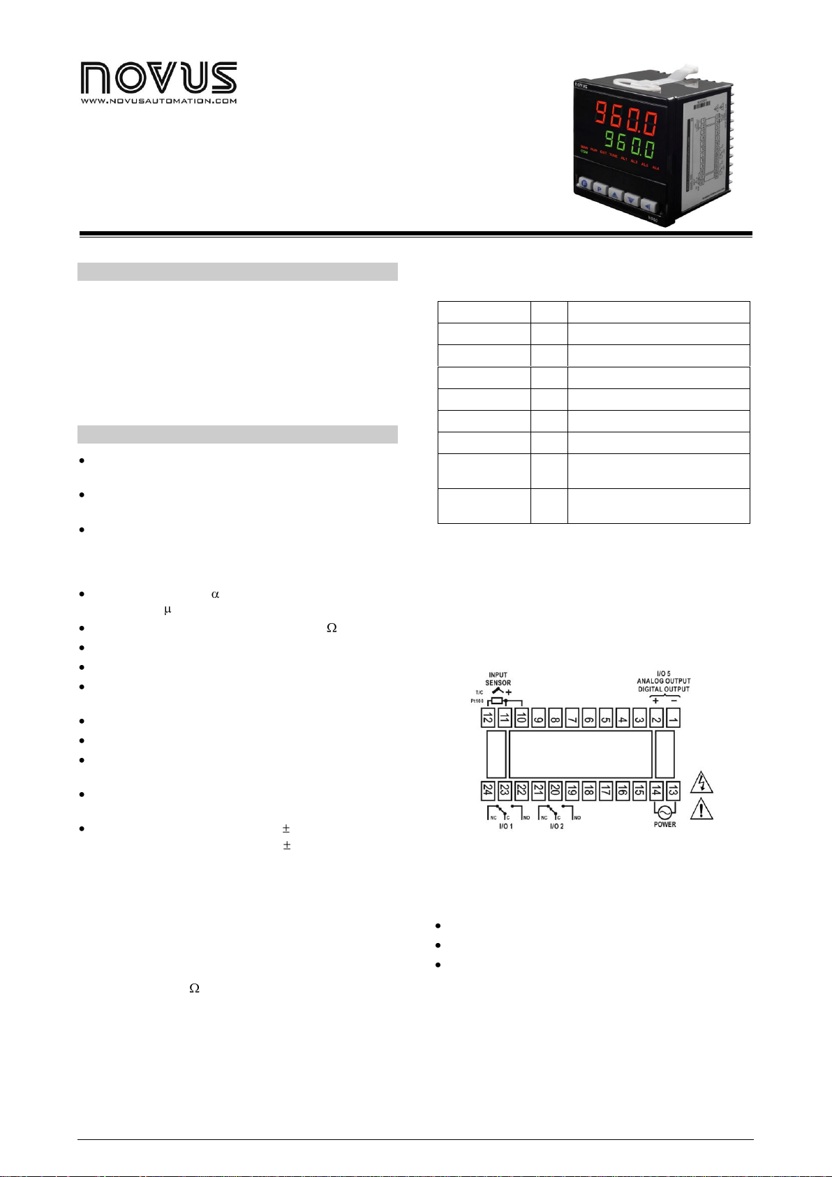
The thermocouples must be connected to the 11 and 12 pins,
observing polarity. A compensation or extension cable is required.
Pt100 sensors must be 3-wire connected to terminals 10, 11 and 12
as Fig. 1 shows. For an adequate cable resistance compensation, all
the conductors must have the same electrical resistance. If the Pt100
is a 4-wire sensor, leave one disconnected by the controller. For 2wire Pt100, use a jumper in the 10 and 11 terminals of the controller
(in this case, there is no auto compensation of the cables length, 1
°C is added to each 0.4 of the total cable resistance).
Table 1 shows the different types of temperature sensor the
controller can accept and the keypad code for their selection.
Table 1 – Sensors the controller is able to accept
POWER SUPPLY
Power is supplied through the terminals 13 and 14. Check the voltage
written on the device box.
ELECTRICAL CONNECTIONS
Fig. 1 shows the controller electrical connections.
Fig. 1 – Controller electrical connections
CONTROL OUTPUTS AND ALARM
There are THREE outputs for process control or alarm.
O/I 1: - Relay output, SPDT 3 A / 250 Vac (3 A / 30 Vdc);
O/I 2: - Relay output, SPDT 3 A / 250 Vac (3 A / 30 Vdc);
O/I 5: - Output current 0-20 mA / 4-20 mA; 500 R max;
- Digital Pulse Output; 12 V / 25 mA;
The output features (control or alarm) are user-defined at the
controller settings. The I/O output is able to provide a current signal
of 0-20 mA or 4-20 mA and a voltage pulse digital signal with no
changes in the controller hardware required.
Different outputs may be set up to perform the same function. The
outputs are automatically turned off whenever the controller
displays the message “ER1”, which accounts for a device fault or
disconnection.
NOVUS AUTOMATION 1/4

SET UP AND OPERATION
TEMPERATURE
AND
SP
Temperature and SP Display: The upper display
shows the current measured temperature. The lower
display indicates the control SP value.
If the measured temperature exceeds the sensor
range limits or the input is open (broken sensor), the
screen will display “- - - -“. In hardware faults, the
screen will display “Er1”
Pr n
Program Execution: Determines the immediate
execution of the ramp and soak program elaborated
at the program level.
no – does not run the program;
yes– runs the program created;
When the control is enabled (run=yes) the selected
program will run immediately.
rVN
Run: In this screen it is possible to enable or disable
the controller action, turning on or off the alarm
control outputs.
0– Does not enable outputs;
1– Disable outputs.
ATVN
Auto-Tune: Enables the auto tune of PID
parameters.
0– Auto-tune disabled;
1– Auto-tune enabled.
pb
Proportional Band: P parameter of the PID
control mode. Expressed as a percentage of the
maximum range of the type of sensor used.
Adjustable from 0 to 500 %.
To use the control mode ON/OFF, set zero (0).
ir
Integral Rate: Value of the integral parameter (I) of
the PID control mode. Expressed as repetitions per
minute. Adjustable from 0.00 to 55.20 repetitions per
minute. It is not displayed when the ON/OFF control
is selected (Pb=0).
dt
Derivative Time: Value of the derivative parameter
(D) of the PID control mode, in seconds. Adjustable
from 0 to 250 s. It is not displayed when the ON/OFF
control is selected (Pb=0).
(t
PWM Cycle Time: Value in seconds of the PWM of
the control output: Adjustable from 0.0 to 99.9
seconds. In processes that use power contactors, this
value must be higher than 10s. In process with solid
state relays, it is possible to use lower values. It is not
displayed if the ON/OFF control is selected (Pb=0).
kyst
Control Hysteresis: It is the ON/OFF control
hysteresis (programmed in a temperature unit). Used
only when the controller is set to ON/OFF control
(pb=0).
Act
Control Action:
rE – Reverse Action usually used for heating.
dir – Direct Action usually used for cooling.
Ai.sp
a2.sp
Alarm 1 and 2 Setpoints: Temperature values that
trigger alarm 1 and 2.
Ptol
Program Tolerance: Maximum deviation between
the program PV and SP. If it is exceeded, the
program is aborted (stops counting the time) until the
deviation falls within the tolerance range. Set zero to
disable this function.
Psp0
Psp7
Program SPs, 0 to 7 Set of 8 SP values that define
the ramp and soak program profile.
Pt1
Pt7
Program Segments Time, 1 to 7 Defines time, in
minutes, of each program segment.
Loop
Program Loop: Option for automatic restart of the
ramp and soak program.
yes – Restart the program automatically.
No – Does not restart the program
automatically.
Fva1
Fva2
Function of Alarm 1 and 2 Selects the function for
Alarms. See Table 2 for a description of functions
and their code, which will be programmed in this
screen.
oFF, iErr, Lo, xi, DiFL, DiFx, DiF
Bla1
bla2
Initial Alarm Blocking Initial alarm blocking function
for alarms 1 to 4.
YES – enables the initial blocking
NO – disables the initial blocking
xya1
xya2
Alarm Hysteresis: Defines the difference between
the temperature value that enables and the one that
disables the alarm.
The controller must be configured before use. The user must assign
each parameter a condition presented as, for example, type of
temperature sensor (“TYPE”), required work temperature (“SP“),
temperature values for alarm triggering (“AISP”), etc.
PARAMETERS ORGANIZATION
The controller parameters are organized in six levels (parameter sets):
Operation / Tuning / Program / Alarm / Output / Calibration
When the controller is turned on, the Operation level is displayed and
remains activated during normal operation. The other levels can be
accessed when changes are required in the controller set up.
To access the other levels, press together the keys P and .
When you reach the required level, which can be identified through
the first parameter shown, use the key P to access the other
parameters in this level. At the end of each level, the controller
returns to the Operation level, showing the process temperature.
When the keyboard is not activated for more than 20 seconds, the
controller returns to the Operation level, showing the process
temperature.
Using and the operator is allowed to change the value of each
parameter shown.
Set up changes are saved in a protected memory and the controller
will use them as soon as the user passes to the next parameter or in
case no key is pressed within 20 seconds. This is not valid for the
RvN parameter, whose setting changes are immediately taken by the
controller.
Controlador N960
PROGRAM LEVEL
OPERATION LEVEL
TUNING LEVEL
CONFIGURATION LEVEL
NOVUS AUTOMATION 2/4
 Loading...