

Controller
UNIVERS
installation and operation of the
tYPE
TYPE
CODE
CHARACTERISTICS
J 0 range: -50 to 760 °C (-58 to 1400 º F )
K 1 range: -90 to 1370 °C (-130 to 2498 ºF)
T 2 range: -100 to 400 °C (-148 to 752 º F )
N 3 range: -90 a 1300 °C (-130 a 2372 ºF)
R 4 range: 0 a 1760 °C (32 a 3200 ºF)
S 5 range: 0 to 1760 °C (32 to 3200 ºF)
Pt100 6 range: -199.9 to 530.0 °C ( -328.0 to 986.0 ºF)
7
4-20 mA
8
J linearization. Programmable range: -110 to 760 °C
4-20 mA
9
K linearization. P rogrammable range: -150 to 1370 °C
4-20 mA
10
T linearization. Programmable range: -160 to 400 °C
4-20 mA
11
N Linearization. Programmable range: -90 a 1370 °C
4-20 mA
12
R Linearization. Programmable range: 0 a 1760 °C
4-20 mA
13
S linearization. P rogrammable range: 0 to 1760 °C
4-20 mA
14
Pt100 linearization. Prog. Range:-200.0 to 530.0 °C
4-20 mA
15
Pt100 linearization Prog. Range:-200 to 530 °C
0 to 50 mV
16
Linear. Programmable i ndication -1999 to 9999
4-20 mA
17
Linear. Programmable i ndication -1999 to 9999
0 to 5 Vdc
18
Linear. Programmable i ndication -1999 to 9999
4 to 20 mA
19
Square Root Extraction
N3000
AL PROCESS CONTROLLER – INSTRUCTIONS MANUAL – V2.1x C
SAFETY SUMMARY
The symbols below are used on the equipment and throughout this
document to draw the user’s attention to important operational and
safety information.
CAUTION OR WARNING:
Read complete instructions prior to
unit.
CAUTION OR WARNING:
Electrical S hock Hazard
All safety related instructions that appear in the manual must be
observed to ensure personal safety and to prevent damage to either
the instrument or the system. If the i nstrument is used in a manner
not specified by the manufacturer, the protection provided by the
equipment may be impaired.
INTRODUCTION
The N3000 is a proc ess controller incorporating a P ID algorithm and
universal inputs (sensor and standard si gnals) and outputs (logical,
relay and analog outputs). It holds in one single instrument all de
main features that are needed for the vast majority of industrial
processes.
CONFIGURATION
INPUT TYPE SELECTION
Select the input type (in parameter “
Pt100
range: -200 to 530 °C (-328 to 986 ºF)
”) from Table 1 below.
OVER-TEMPERATURE PROTECTION
When designing any control system it is essential to consider what
will happen if any part of the system should fail. In temperature
control applications the primary danger is one in which the heating
remains constantly on. In any application where physical injury or
destruction of equipment might occur, it is recommend to install an
independent protection equipment, with a separate temperature
sensor, to disable the heating c ircuit in case of overheating. Please
note that the alarm relays within the controller wil l not give protection
under all failure conditions.
NOVUS AUTOMATION 1/9
Table 1 - Input Types
OUTPUTS, ALARMS AND DIGITAL INPUTS CONFIGURATION
The controller input/output c hannels can assume multiple functions,
depending on configuration: control output, alarm output, digital
output, digital input, and PV or SV analog retransmission. These
channels are identified as I/O1, I/O2, I/O3, I/O4, I/O 5 and I/O6.
The basic controller model comes loaded with:
• I/O1 and I/O2 - SPDT relay output;
• I/O3 and I/O4 – SPST relay output;
• I/O5 - analog output (0-20 or 4-20 mA), pulse 10 V max, digital I/O;
• I/O6 – Digital Input;
The function code of each I/O can be selec ted among the options on
Table 2. Only valid function codes are displayed for each I/O (for
example, I/O1, which is a relay , can be confi gured with functi ons 0 to
5 only; on the other hand, I/05 can perform all 16 functions).
The description for the functions follows:
• CODE 0 - No function. The I/O channel programmed with code 0
will not be used by the controller. It is available to be used by serial
communication as digital output.
• CODES 1 to 4 - Alarm output - Available for all I/O channels
(except I/O6). The selected channel can be used as output to
Alarms 1 to 4.
• CODE 6 - Digital input - Standard for I/O5 and I/O6.
Closed: Manual control
Opened: Automatic control
Controller N3000
rvn
0
1
2
3
4
5
6
7
8
9
10
11
12
13
14
15
16
off
No active alarm. This output can be used as a digital
output to be set by t he serial communication.
(input Error)
ierr
Alarm will be ON if P V sensor breaks, input signal is
Event Alarm
Soak)
rs
Can be activated at a specific segment of ramp and
resistance f ail
rfail
lo
SPAn
PV
ki
SPAn
PV
difl
SV
PV
SV - SPAn
SV
PV
SV - SPAn
difk
SV
PV
SV + SPAn
SV
PV
SV + SPAn
dif
SV
PV
SV + SPAn
SV - SPAn
SV
PV
SV - SPAn
SV + SPAn
SPA1
SPA2
A1t1
A1t2
A2t1
A2t2
• CODE 7 - Digital input - Standard for I/O5, I/O6 and key.
Start/Stop input (“
”: YES / no).
Closed: outputs enabled
Opened: outputs disabled
• CODE 8 - Digital input - Standard for I/O5, I/O6 and
key.
Closed: remote SP (4-20 mA in remote SP input)
Opened: main SP (internal programmed SV)
• CODE 9 - Digital input - Standard for I/O5, I/O6 and key.
Opened: enables R&S program
Closed: holds R&S program (the program resumes when the
contact is opened again)
CODE I/O TYPE I/O FUNCTION
Digital Output Digital Output to be set by the serial comm.
Digital Output Alarm 1 Output
Digital Output Alarm 2 Output
Digital Output Alarm 3 Output
Digital Output Alarm 4 Output
Digital Output PWM Control Output
Digital Input Automatic/Manual mode change
Digital Input Run/Stop mode change
Digital Input Select Remote Set Point Input
Digital Input Executes/Holds selected ramp and soak profile
Digital Input Enable/Disable R&S profile 1 selection
Analog Output 0 to 20mA Analog control out put
Analog Output 4 to 20mA Analog control output
Analog Output 0 to 20mA PV retransmission
Analog Output 4 to 20mA PV retransmission
Analog Output 0 to 20mA SP retransmission
Analog Output 4 to 20mA SP retransmission
Table 2 - I/O channel f unctions
• CODE 10 - Digital input - Standard for I/O5, I/O6 and key.
Selects R&S program 1. Used to alternate between the main
Setpoint and a second Setpoint defined by the R&S program 1.
Closed: selects program 1
Opened: uses main Setpoint
• CODE 11 - Analog control output - I/O5 only. 0-20 mA control
output.
• CODE 12 - Analog control output - I/O5 only. 4-20 mA control
output.
• CODES 13 to 16 - Analog retransmission. I/O5 only. Configures
I/O5 to output a 0-20 mA or 4-20 mA analog signal proportional to
PV or SP.
REMOTE SETPOINT
The remote Setpoint (SP) is enabled by an external digi tal signal in
either I/O5 or I/O6, when programmed with the code 8 (Select remote
SP input).
An external resistor shunt of 100 Ω is required between the terminals
7 and 8.
ALARMS FUNCTION
The controller has 4 alarms. The alarms can the configured to
operate in any of the nine functions listed on Table 3.
• Open sensor
It is activated whenever the input sensor is broken or disconnected.
• Event alarm
It activates alarm(s) in specifi c segments of the program. See item
7.2 in this manual.
• Event alarm
Detects a heater broken condition, by monitoring the load current
when the control output is ac tivated. This alarm functi on requires an
optional device (option 3). Details of the "resis tance fail" option can
be found in a specific documentation that is sent with the product
when the option is purchased.
TYPE PROMPT
Disabled
Sensor Break
(ramp and
Detection
Low Alarm
High Alarm
LOW
Differential
HIGH
Differential
Differential
out of range or Pt100 is shorted.
Detects a heater br oken condition
positive SPAn
positive SPAn
positive SPAn
Table 3 - Alarm functions
ACTION
soak program.
negative SPAn
negative SPAn
negative SPAn
Where SPAn means “SPA1”, “SPA2”, “SPA2” and “SPA4”.
• Minimum value
It is activated when the measured value i s below the v alue defined i n
the alarm Setpoint.
• Maximum value
It is activated when the meas ured val ue is above t he val ue defi ned in
the alarm Setpoint.
• Differential (or Band)
In this function, the parameters “
”, “
” represent the PV
deviation as compared to the main SP.
In a positive deviation, the di fferential alarm will be triggered when
the measured value is out of the range defined in:
( SP – Deviation) and (SP + Deviation)
In a negative deviation, the differenti al alarm will be triggered when
the measured value is within the range defined above.
• Minimum differential
It is activated when the measured value is below the value defined in.
(SP - Deviation)
• Maximum differential
It is activated when the measured value is above the value defined in:
(SP + Deviation)
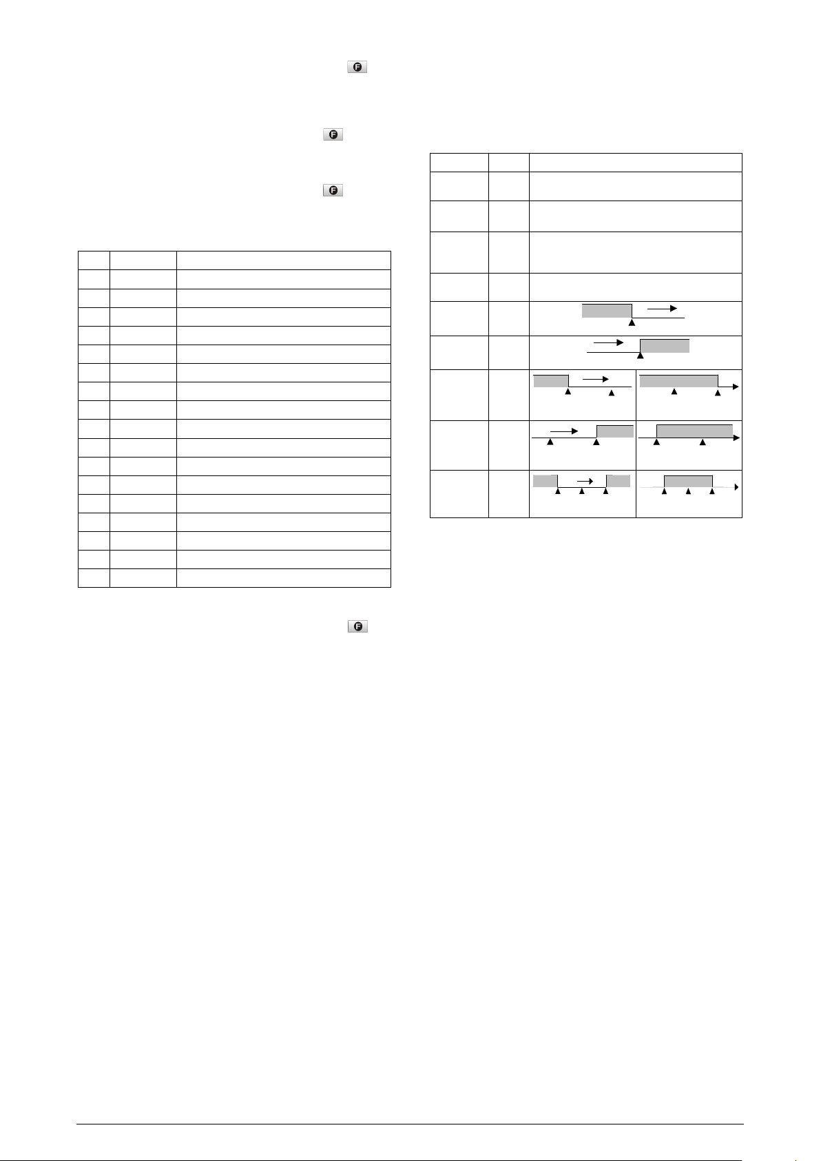
ALARM TIMER FUNCTIONS
Alarms 1 and 2 can be programmed to have timer functions. The 3
modes of operation are:
1- Pulse 2- delayed actuation 3- Oscillator
The desired function can be achieved programming the parameters
”, “
”, “
” and “
“
” (see Table 4).
The LEDs associated to the alarms will light when the alarm condition
is recognized, not following the actual state of the output, which may
be temporarily OFF because of the temporization.
NOVUS AUTOMATION 2/9
Alarm Function
T1 T2 ACTION
Alarm Event
Alarm
Output
Alarm Event
Alarm
Output
T2
Alarm Event
Alarm
Output
T1
Alarm Event
Alarm
Output
T1
T2
T1
SPLL
SPkL
SfSt
ovLL
ovkL
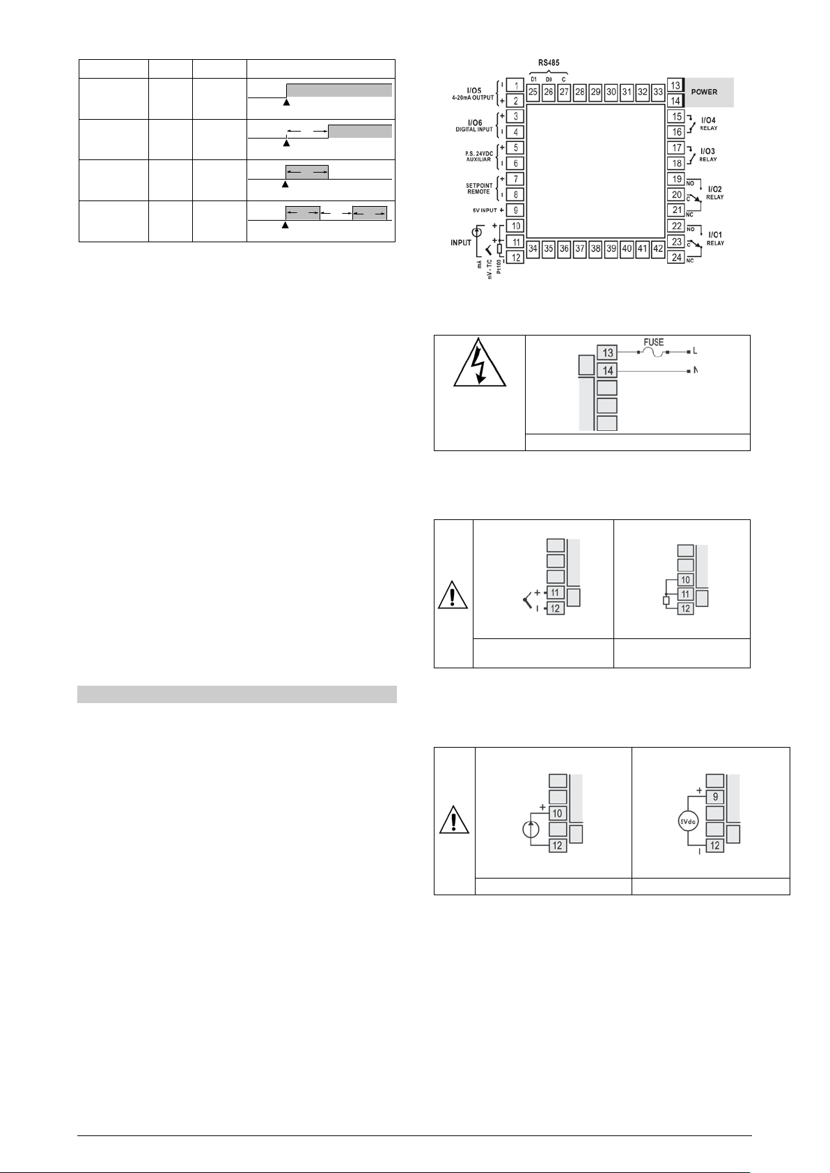
irreversible damage
will occur
Figure 2 – High and Low Voltage AC power w iring
wiring
three conductors
Figura 5 – connection of 4-20 mA
Figura 6 – Connection of 5 Vdc
Normal 0 0
Delayed 0 1s to 6500s
Controller N3000
Pulse 1s to
6500s
Oscillator 1s to
6500s
Table 4 - Advanced Timer A larm (for alarms 1 or 2)
0
1s to 6500s
ALARM INITIAL BLOCKING
The initial blocking opti on inhibits the alarm from being recognized if
an alarm condition is present when the controll er is first energized.
The alarm will actuate only after the occurrence of a non alarm
condition followed by a new occurrence for the alarm.
The initial blocking is disabled for the sensor break alarm function.
SQUARE ROOT EXTRACTION
Available when input type 19 is sel ected. The indicator displays the
square root of the current signal input applied to terminals 22 and 24.
ANALOG RETRANSMISSION OF PV AND SP
The analog output, when not used for control purposes, is available
for retransmitting the SV and SP values in 0-20 or 4-20 mA. Thi s
analog output is electrically isolated from other inputs and outputs.
The analog output signal is scaleable, with the output range
determined by the values programmed in the parameters “
”. To obtain a voltage output, connect a resistor shunt to the
“
” and
current output terminals (terminal 1 and 2).
Figure 1 – Back panel terminals
POWER WIRING
If high voltage is
applied to a low
voltage input,
INPUT CONNECTIONS
• Thermocouple and Voltage (Volts and mV) input connect as i n
Figure 3.
SOFT START
Defines the time i nterval for the output to reach its maximum value
(100 %). The soft start value is programmed in “
parameters “
” and “
INSTALLATION / CONNECTION
Insert the unit into the panel cut-out and slide the mounting clamp
from the rear to a firm grip at the panel.
All electrical connecti ons are made to the screw terminals at t he rear
of the controller. They accept wire siz es from 0.5 to 1.5 mm2 (16 to
22 AWG). The terminals should be tightened to a torque of 0.4 Nm
(3.5 lb in).
To minimize the pick-up of electrical noise, the low voltage DC
connections and the sensor input wiring s hould be routed away from
high-current power conductors. If this is impractical, use shielded
cables. In general, keep cable lengths to a minimum.
RECOMMENDATIONS FOR INSTALLATION
• Input signal wires s hould be laid out away from power lines and
preferably inside grounded conduits.
• Instrument mains (line) supply should be suitabl e for this purpose
and should not be shared.
• In controlling and monitoring applicati ons, possible consequences
of any system failure mus t be considered in advanc e. The internal
alarm relay does not warrant total protection.
• Use of RC filters (47 R and 100 nF, serial) are highly
recommended when driving solenoids, contactor coils or other
inductive loads.
NOVUS AUTOMATION 3/9
”. See also
Figure 3 – T/C and Voltage
Figura 4 – Pt100 wiring wi th
”.
• RTD (Pt100)
Figure 4 shows the Pt100 wiring, for 3 conductors. Terminals 10, 11 and 12
must have the same wire resistance for proper cable length compensation.
For 2 wire Pt100, shor t circuit t erminals 10 and 11.
• 4-20 mA:
Refer to Figure 5. (The controller provides an internal electronic
shunt for the input current. No changes in the circuit are necessary).
• Alarm and output connection
When I/O channels are set up as output channels, they must have
their capacity respected, according do specifications.
• Remote setpoint:
The remote Setpoint (SP) is enabled by an external digi tal signal in
either I/O5 or I/O6, when programmed with the code 8 (Select remote
SP input).An external resistor shunt of 100 is required between the
terminals 7 and 8.
DIGITAL INPUT

Controller N3000
fFvn
f.fvnc
tYPE
I/O5 and I/O6 can be used as digital inputs, accepting either dry contact
or NPN open collector signals. Figure 7 shows a switch driving the I/O6
digital input. The digital input at I/O5 is driven only by dry contact
signals. Figure 8 shows a typical digital input wiring for I/O5.
Figure 7 – Digital input at I/O6 Figure 8 – Di git al i nput at I/ O5
DIGITAL OUTPUT
I/O5 can also be configured as digital out put. An example of usage is
shown in Figure 9. I/O5 is electrically isolated from the sensor input.
Figure 9 – I/O5 digit al output wiring.
KEY AND DIGITAL INPUT (I/O6) FUNCTIONS
Both the key and the I/O6 digital input can be programmed to execute
functions 7, 8, 9 and 10 shown in Table 2. The key function is
configured in parameter “
”. The digital input function is
configured in parameter IO6.
The digital input can also be configured for function 6: Auto/Manual
mode change.
Programmable FUNCTION Key: Can be assigned to the
-
special functions described for the
parameter.
When the controller is turned on, its firmware version i s display ed for
3 seconds, after which the controller starts normal operation. The
values of PV and SV are displayed and the outputs are enabled.
Before the controller is ready to be used in a given process, it
requires some basic configuration, such as:
• Input type (T/C, Pt100, 4-20 mA,...) at the “
” prompt,
according to Table 1;
• Output type at “I/O 1”, “I/O 2”,... “I/O 6” prompts (see Table 2);
• Setpoint variable SV. Set the remaining parameters.
• PID parameters (or hysteresis for ON/OFF control)
Other functions, including alarms, ramp and s oak, timer, digital input,
etc., may be useful for a better system performanc e. The parameters
are grouped in 7 cycles.
CYCLE ACCESS
1- Operation Free access parameters *
2- Tuning
3- R&S Program
4- Alarms Reserved access parameters **
5- Input Configuration
6- I/Os
7- Calibration
*These parameters can be viewed but not changed if the cycle is
protected.
**Requires a key combination to access the cycle.
OPERATION
The front panel is shown in Figure 10.
Press
the next one.
and simultaneously to move from one cycle to
Press to advance and to go back in the menu cycle.
Keep pressing the or key to move fast forward or backward.
At the end of each cycle the controller returns to the operation cycle.
PROGRAM SECURITY
Each menu cycle can be locked (protected) by pressing
and
simultaneously for 3 seconds. Press and for 3
seconds to unlock. A short blink of the display confirms the
lock/unlock change.
Figure 10 - Front panel part s
Status display / PV: shows the value of PV (Process Variable).
When in programming mode, shows the parameter name.
Parameter display / SV: shows the SV (Setpoi nt Vari abl e) value and
the value of other parameters of the controller.
COM Indicator: Flashes when communication messages are sent by
the controller.
TUNE Indicator: Lights during the execution of PID automatic
tunning.
MAN Indicator: Lights when the controller is in manual.
RUN Indicator: Lights when the control ler is active, wi th control and
alarm outputs enabled.
OUT Indicator: For relay or pul se control output, reflects the actual
state of the output. If an analog output is assigned for control, lights
continuously.
A1, A2, A3 and A4 Indicators: Status of the alarms.
- PROG key: used to walk through the menu cycles
- BACK key: go back to the previous displayed parameter
For further protection, the unlock operation through the keypad may
be disabled by c hanging the position of an internal strap insi de the
controller:
When PROT is OFF, the user is allowed to lock and unlock the
cycles using the keypad as explained above. If PROT is ON, the
cycles lock/unlock operation is disable.
- INCREASE and - DECREASE keys: Used to change
parameter values
NOVUS AUTOMATION 4/9

Controller N3000
PV Indication
(Red)
SV Indication
(Green)
Ern
avto
PV Indication
(Red)
MV Indication
(Green)
display shows PV value and the lower display shows
the percentage of MV applied to the control output.
When in manual control the MV value can be manually
changed. When in auto mode the MV value can only be
Pr n
programs possible). Refer to chapter 7 for R&S
rvn
atvn
enables the auto tuning of the PID
Pb
PROPORTIONAL BAND: Percentage of maximum
xyst
CONTROL HYSTERESIS (in engIneering. units): This
‘ ir‘
INTEGRAL RATE: Integral time constant in repetitions
dt
DERIVATIVE TIME: Derivative time constant, in
(t
CYCLE TIME: PWM period in seconds. Can only be
act
rE
dir
bias
ovll
ovxl
sfst
Sp.a1
Sp.a2
Sp.a3
Sp.a4
tbas
: Selects the time base for the ramp and
0
Pr n
ptol
Psp0
Psp7
values which define the ramp and soak profile
Pt1
Pt7
Pe1
Pe7
rS
lp
Fva1
Fva2
Fva3
Fva4
bla1
bla2
bla3
bla4
xya1
ALARM 1 HYSTERESIS: Defines the differential
xya2
xya3
xya4
A1t1
A1t2
alarm 1 output, after being ON during the time
A2t1
A2t2
features that can be achieved with these time
CONFIGURATION PARAMETERS
OPERATION CYCLE
PV AND SV INDICATION: The status display shows
the present value of PV (Process Variable). The
parameter display shows SV (Set Variable).
The status display shows “- - - -“ whenever PV exceeds
the maximum range or there is no signal at the input. In
case of hardware error the status display will show
where n is the error c ode.
CONTROL MODE: YES indicates automatic control
mode (closed loop, PID or ON/OFF). NO indicates
manual control mode (open loop). Bumpless transfer
from auto ↔ to manual mode is available. If in doubt
program YES.
MANIPULATED VARIABLE VALUE (MV): The upper
viewed.
To distinguish the MV display from the SV display, the
MV is shown flashing intermittently.
RAMP AND SOAK PROGRAM SELECTION: Selects
the ramp and soak program to be executed (7
description.
CONTROL ENABLE: YES means that the control
output and alarms are enabled and NO means they
are disabled.
AUTO TUNING CYCLE
AUTO-TUNE: YES
parameters and NO dis ables it.
input span. 0 to 500 %. Selec t zero for ON/OFF control.
parameter is only shown for ON/OFF control (Pb=0).
per minute (Reset) .
RAMP AND SOAK PROFILE PROGRAMMING CYCLE
TIME BASE
soak. Valid for all profile programs.
- PT1 to PT7 values are in seconds;
1 - PT1 to PT7 values are in minutes;
PROGRAM TO BE VIEWED: Selects the ramp and
soak profile program to be edited/viewed in the
following cyc le prompts (7 programs available).
,
RAMP AND SOAK TOLERANCE: maximum deviation
between PV and SV. Whenever this deviation is
exceeded the time counter is halted until deviation
lowers to within the tolerance. Set zero to disable this
function.
RAMP AND SOAK SET POINTS (0 to 7): Set of 8 SV
segments. See also PT1 to 7 and PE1 to 7 below.
RAMP AND SOAK SEGMENTS TIME (1 to 7): Set of
7 time intervals in minutes or seconds (9999 max.) for
the 7 segments of the r am p and soak program.
RAMP AND SOAK EVENT (1 to 7): Set of 7 values
that define which alarms must be activated during a
ramp and soak program segment. Alarm function
depends on “
LINK TO PROGRAM: Number of the next profile
program to be linked to follow the current profile.
Profiles can be linked to make larger programs of up
to 49 segments.
” setting (Table 3).
ALARM CYCLE
ALARM 1 FUNCTION: Select options from Table 3.
ALARM 2 FUNCTION: Select options from Table 3.
ALARM 3 FUNCTION: Select options from Table 3.
ALARM 4 FUNCTION: Select options from Table 3.
ALARM BLOCK 1 TO 4: This func tion blocks the alarm
at power-up when the units is first energized.
YES enables and NO inhibits this blocking function.
When enabled the alarm will not be active at power-up
waiting for PV (Process Variable) to reach a non-alarm
situation. From this point on the alarm will be free to
actuate should a new alar m situation occur.
seconds.
viewed if proportional band is other than z ero.
CONTROL ACTION: For Auto Mode onl y.
•
Reverse Action usually used for heating.
•
Direct Acti on usually used for cooling.
Offset for MV (manual reset). Range: -100 % to +100
%. Default value: 0.
OUTPUT LOW LIMIT: minimum percentage value for
MV (Manipulated Variable) when in automatic control
and PID. Default val ue: 0.0 %
OUTPUT HIGH LIMIT: Maximum percentage value for
MV when in automatic control and PID. Default value:
100.0 %
SOFT START: Time in seconds during which the
controller limits the MV value progressively from 0 to
100%. It is enabled at power up or when the control
output is activated. If in doubt set zero.
ALARM PRESET: Tripping point for alarm 1, 2, 3
and 4.
NOVUS AUTOMATION 5/9
range between the PV value at which the alarm is
turned on and the value at which it is turned off (in
engineering units).
ALARM 2 HYSTERESIS: Same as above.
ALARM 3 HYSTERESIS: Same as above.
ALARM 4 HYSTERESIS: Same as above.
ALARM 1 TIME 1: Defines the time (6500 sec. max.)
during which the alarm 1 output will be ON when
alarm 1 is acti ve. Program zero to disable this function.
ALARM 1 TIME 2: Defines the OFF state time for the
selected on ALARM 1 TIME 1. Program zero to
disable this function.
ALARM 2 TIME 1: Defines the time (6500 sec. max.)
during which the alarm 1 output will be ON when
alarm 1 is acti ve. Program zero to disable this function
ALARM 2 TIME 2: Defines the time during which the
alarm 2 output will be, after being ON during the time
selected on ALARM 2 TIME 1. Program zero to
disable this function. Table 4 shows the advanced
functions.

Controller N3000
type
connected to the process variable input. Refer to
dppo
vnIt
offs
spll
Linear inputs: Sets the lower range for SV and PV
spxl
d PV
rsll
rsxl
bavd
addr
Io 1
Io 2
Io 3
Io 4
Io 5
I o 6
f.fvnc
0
7
8
9
10
Programming
atvn
Tbas
fva1 -
fva4
type
io1
avto
pb
pr n
bla1 -
bla4
dppo
io2
hyst
Ptol
kya1 -
kya4
vnit
io3
pr n
ir
psp0 -
psp7
A1t1
offs
Io4
rvn
dt
pt1 -
pt7
a1t2
spll
Io5 (t
pe1 -
pe7
a2t1
spkl
Io6
a(t
Lp
a2t2
rsll
f.fvnc
bias
Rskl
Inl(
INPUT LOW CALIBRATION: Sets the Process
Inx(
INPUT HIGH CALIBRATION: Sets the Process
ovll
OUTPUT LOW CALIBRATION: Sets the analog
Ovx(
(j l
xtyp
HARDWARE TYPE: Configures the controller to
onal hardware
(accessories). The parameters menu will show the
Rsl(
Remote Set Point low calibration (offset). Several
Rsx(
CONFIGURATION CYCLE
INPUT TYPE: Selects the input signal type to be
Table 1.
This is the first p arameter to be set.
DECIMAL POINT POSITION: For input types 16, 17,
18 or 19 only. Selects the decimal point position to be
viewed in both PV and SV.
TEMPERATURE INDICATION IN ºC OR ºF: Selects
the display indication to be in ºC or ºF. Only available
if input type is other than 16, 17, 18 or 19.
SENSOR OFFSET: Offset value to be added to the
PV to compensate sens or error. Default value: zero.
SET POINT LOW LIMIT:
indication.
- T/C and Pt100 inputs: sets the lower range for SV.
SET POINT HIGH LIMIT:
- Linear inputs: Sets the upper range for SV an
indication.
- T/C and Pt100 inputs: sets the upper range for SV.
REMOTE SET POINT LOW LIMIT: Selects the lower
range for indication of the Remote Setpoint.
REMOTE SET POINT HIGH LIMIT: Selects the upper
range for indication of the Remote Setpoint.
DIGITAL COMMUNICATON BAUD RATE
SELECTION:
0: 1200bps; 1: 2400bps; 2: 4800bps; 3: 9600bps; 4:
19200bps.
SLAVE ADDRESS SELECTION: Identifies a slave in
the network. The possible address numbers are from 1
to 247.
I/O CYCLE (INPUTS AND OUTPUTS)
I/O 1 FUNCTION: Selects the I/O function to be used
at I/O 1 (relay 1). Options 0 to 5 are possible for this
output. It is normally used as option 5, PWM main
control output. Refer to Table 2 for func tions.
I/O 2 FUNCTION: Selects the I/O function to be used
at I/O 2 (relay 2). Options 0 to 5 are available. This
output is normally used as alarm output. See Table 2
for functions.
I/O 3 FUNCTION: Selects the I/O function to be used
at I/O 3 (option 1). I/O 3 can be a relay output or a
digital input/output. Functions 0 to 10 are available.
Refer to Table 2 for functions. The presence of this I/O
option is detected by the controller and the prompt
menu will only be shown if the expansion option is
available.
I/O 4 FUNCTION: Selects the I/O function to be used
at I/O 4 (option 2). I/O 4 can be a digital input/output.
Functions 0 to 10 are available. Refer to Table 2 for
functions. The prompt menu will only be shown if the
expansion option is present.
I/O 5 FUNCTION: S elects the I/O function to be used
at I/O 5 (Analog Output). Functions 0 to 15 are
available (See Table 2). This option is normally used
for main control output or PV analog retransmission.
I/O 6 FUNCTION: Selects the I/O function to be used
at I/O 6 (Digital Input). Options 0, 6, 7, 8, 9 and 10 are
possible for this input. Refer t o Table 2 for functions.
F KEY FUNCTION: Selects the I/O function assigned
to the front panel
NOVUS AUTOMATION 6/9
- Key not used;
- Start/Stop the controller (RUN function);
- Select remote setpoint;
- Execute/Hold ramp and soak profile;
- Enable/Disable ramp and soak profile 1;
Details on these f unctions are described in section 5. 2.
key. Available functions are:
Figure 7 shows the sequence of cycles and parameters presented in
the indicator display. There are parameters that must be defined for
each alarm available.
Operation
Cycle
Auto
Tuning
Cycle
Cycle
Alarm
Cycle
Configuration
Cycle
I/Os
Cycle
PV e SP
PV e MV
Figure 10 - Sequence of cy cl es and paramet ers pr esent ed in the c ontroll er display
CALIBRATION CYCLE
All input and output types are factory calibrated. This cycle shoul d
only be accessed by experienced personnel. I f in doubt do not press
or keys in this cycle.
the
Variable low calibration (offset). Several keystrokes at
or
might be necessary to increment one
digit.
Variable span calibration (gain).
current output low calibration (offset).
OUTPUT HIGH CALIBRATION: Sets the analog
current output s pan calibration (gain).
COLD JUNCTION OFFSET CALIBRATION: Sets the
cold junction offset calibrat ion.
recognize the actual installed opti
parameters relative to the optional har dware:
0 - no optionals or c/ RS485 only;
1 - relay 3 (I/O 3);
2 - Digital I/O (2 inputs/outputs : I/O3 and I/O4);
3 - Heater break prot ection (option);
REMOTE SET POINT LOW CALIBRATION: Sets the
keystrokes at or
increment one digit.
REMOTE SET POINT HIGH CALIBRATION: Sets the
Remote Set Point span calibration (gain) .
might be necessary to

Controller N3000
SP
time
T1
T2
T3
T4
T5
SP0
SP1
SP2
SP3
SP4
SP5
SP6
SP7
T6
T7
SV
time
T1
T2
T3
SP0
SP1
SP2
SP3
T4=0
Ptol
SV
time
T1
T2
T3
T4
T5
T1
T2
T3
T4
SP0
SP1
SP2
SP3
SP4
SP5 / SP0
SP1
SP2
SP3
SP4
Program 1
Program 2
rS
PE 0
PE 5
CODE
ALARM 1
ALARM 2
ALARM 3
ALARM 4 0
1 X
2 X
3
4
X
5 X X
6 X X
7 X X X
8
9
X
X
10
X
X
11
X X
X
12
X
X
13
14
X X
X
15
X X X
X
Prn
rvn
PtoL
rvn
Avto
Atvn
rvn
Large Oscillat ion
Increase
Slow Response
Incre ase
Large Oscillat ion
Decrease
Slow Response or Instability
Decrease
inL(
ink(
RAMP AND SOAK PROFILE PROGRAM
Seven ramp and soak profiles with up to 7 segments each can be
programmed. Longer profiles of up to 49 segments can be created by
linking 2 or more profiles.
Figure 11 - Example of a complete ramp
and soak profile
To execute a profile with fewer segments just program 0 (zero) for the
time intervals that follow the last segment to be executed.
The program tolerance “
between PV and SV for the execution of the profile. If this devi ati on is
exceeded, the program will be interrupted until the deviation falls to
within the tolerance band.
Programming 0 (zero) at this prompt disables the tolerance and the
profile execution will not t o be halted even if PV does not follow SV
(time priority as opposed to SV priority).
The ramp and soak event function is used to acti vate alarms at any
segment of program 1. This applies only to program 1.
LINK OF PROGRAMS
It is possible to create a more complex program, with up to 49
segments, joining the seven programs. This way, at the end of a
program execution the controller immediately starts to run another one.
When a program is created, it must be defined in the “LP" screen
whether there will be or not another program.
To make the controller run a given program or many programs
continuously, it is only necessary to l ink a program to i tself or the last
program to the first.
Figure 12 - Example of a pr of ile
with fewer segments. ( T4 i s set 0)
” defines the maximum deviation
To configure and execute a ramp and soak program:
• Program the tolerance value, SV, time and event.
• If any event alarm is required program the ramp and soak event
function.
• Set the control mode to automatic.
• Select ramp and soak program to be executed at prompt
• Start control at the
prompt by selecting YES.
(0 to 7)
Before executing the program the controller waits for PV to reach the
first set point SP0 if
is different than zero.
Should any power failure occur the controller resumes at the
beginning of the segment it currently is.
AUTO TUNE
During auto tune the process is controlled in ON/OFF mode at the
programmed SetPoint (SV). Depending on the process
characteristics large oscil lations above and bel ow SV may occur and
auto tuning may take several minutes to be concluded.
The recommended procedure is as follows:
• Disable the control output at the
• Select auto mode operation at the
• Disable the ramp and soak function (select NO) and program a new
SV value other than the present PV (close to the desired set point).
• Enable auto tuning at the
• Enable the control output at the
During the auto tune procedure the soft-start function will not operate
and large oscillati ons will be induc ed around the setpoint. Make sure
the process can accept these oscillations and fast control output
changes.
If auto tuning results are not satisfactory refer to T able 6 for manual
fine tuning procedure.
PARAMETER RESPONSE SOLUTION
Proportional Band S low Response Decrease
prompt by selecting NO.
prompt by selecting YES.
prompt by selecting YES.
prompt by selecting YES.
EVENT ALARM
To enable this event function the alarms to be activated must be
selected for
prompts. The number to be programmed at the prompt defines the
alarms to be activated (Table 5).
NOVUS AUTOMATION 7/9
Figure 13 - Example of two linked programs
function and are programmed at the
X X
X
X X X
Table 5 - Event codes for ramp and soak
to
Integral Rate
Derivative Ti me
Large Oscillat ion Increase
Table 6 - Suggestions for manual tuning of PID param eters
CALIBRATION
INPUT CALIBRATION
All inputs are fac tory c al ibrated and recal i bration s houl d only be done
by qualified personnel. If you are not fami liar with these procedures
do not attempt to calibrate this instrument. The calibration steps are:
a) Select the input type to be calibrated.
b) Set the desired upper and lower display limits.
c) At the input terminals inject an electric al signal corresponding to
a known indication value a little higher than the lower display
limit.
d) Select the
PV so that it matches the injected signal.
e) Inject a signal that corresponds to a v alue a little lower than the
upper limit of the display.
f) Select the
PV so that it matches the injected signal.
g) Repeat steps c) to f) to improve calibration.
Note: When verifications are proceded, note if the Pt100
excitation/activation current the calibrator requires i s compliant to the
Pt100 excitation current used in this instrument: 0.750 mA.
prompt. Through the and keys adjust
prompt. Through the and keys adjust

Controller N3000
ovLL
ovkL
avto
rvn
ovLC
ovkC
MESSAGE
POSSIBLE PROBLEM
-----
Open input. No sensor is connected or the sensor is
broken.
Err1
Err6
spxl
spll
D1 D D + B Bidirectional data line
Terminal 25
D0
D:
D - A Inverted bidir ectional data line
Terminal 26
Optional connection to improve
GND
ANALOG OUTPUT CALIBRATION
1. Select type 11 or 12 at the I/O5 prompt.
2. Connect a current meter at the analog output.
3. Disable the auto-tune and soft-start functions.
4. Set the output low limit
to 100.0 %.
5. Select the manual mode at the
6. Enable the output at the
7. At the operation cycle, set the MV to 0.0 %.
8. At the output low cal ibration
key until the mA meter reads zero mA. Approach this value
from above.
9. Set 100.0 % for the manipulated variable (MV).
10. At the output high calibration
key unti l the mA meter reads 20 mA. Approach this value
from below.
11. Repeat steps 7. to 10. as necessary.
PROBLEMS WITH THE CONTROLLER
Connection errors or improper configuration will result in malfuncti oning
of the controller. Carefully revise all cable connections and programming
parameters before operating the unit.
Some error messages will help the user identify possible problems.
Pt100 cable resistance is too high or the sensor is badly
connected.
Different messages other than the ones above should be reported to
the manufacturer. Please inform the serial number if this should
occur. The serial number can be viewed at the display by pressing
key for about 3 seconds.
the
The software version of the instrument can be viewed at the time the
unit is powered.
When not properly configured, the instrument may show false error
messages, particularly those related to the type of input selected.
The controller also has a vis ual alarm (the display fl ashes) when the
PV value is out of the range set by
SERIAL COMMUNICATION
The indicator can be supplied with an asynchronous RS-485 digital
communication interface for master-slave connection to a host
computer (master).
The indicator works as a slave only and al l commands are started by
the computer which sends a request to the slave address. The
addressed unit sends back the requested reply.
Broadcast commands (addressed to all indi cator units in a multidrop
network) are accepted but no reply is sent back in this case.
CHARACTERISTICS
• RS-485 compatibility with two-wire connection f rom the host to up
to 31 slaves i n a multidrop network topology. Up to 247 units can
be addressed by the MODBUS RTU protocol. Maximum network
distance: 4,000 feet. T ime of indicator dis connection: Maximum of
2 ms after the last byte.
• Te communication signals are elec trically isolated from the rest of
the instrument, and can be 1200, 2400, 4800, 9600, 19200, 38400,
and 57600 bps.
• Number of data bits: 8, without parity or pair parity
• Number of stop bits: 1
• Time to start response transmission: up to 100 ms after
acknowledging the command.
• Protocol: MODBUS (RTU)
NOVUS AUTOMATION 8/9
to 0.0 % and the output high li mit
prompt.
prompt.
prompt, press the and
prompt, press the and
and
.
RS485 INTERFACE: ELECTRICAL CONNECTION
The RS-485 signals are:
C
communication performance
Terminal 27
SPECIFICATIONS
DIMENSIONS: ................. 96 x 96 x 92 mm. Peso Aproximado: 350 g
TERMINAL CONECCTION: ..... 24 screws acceping 6.3 mm fork lugs
PANEL CUT-OUT: ................................... 93 x 93 mm (+0.5 -0.0 mm)
POWER: ..................................... 100 a 240 Vac/dc (±10 %), 50/60 Hz
Optional: ............................................................ 24 Vac/dc ±10 %
Max. Consumption: ................................................................ 9 VA
ENVIRONMENTAL CONDITIONS:....................................... 5 a 50 ºC
Relative humidity (maximum): .............................80 % up to 30 ºC
.................... For temperatures above 30 ºC, decrease 3 % per ºC
....... Installation category II. Pollution degree 2. Altitude < 2000 m
INPUT .................... Keyboard selection of input type (refer to Table 1)
Internal resolution: .................................................. 19500 levels
Display resolution: ................. 12000 levels (from -1999 to 9999)
Input sample rate: .................................................... 5 per second
Accuracy: .......... Thermocouples J, K e T: 0.25 % of span ±1 ºC
............................. Thermocouples N, R, S: 0.25 % do span ±3 ºC
...................................................................... Pt100: 0.2 % of span
.................................... 4-20 mA, 0-50 mV, 0-5 Vdc: 0.2 % of span
Input impedance: . 0-50 mV, Pt100 and thermocouples: >10 MΩ
................................................................................. 0-5 V: >1 MΩ
................................................. 4-20 mA: 15 Ω (+2 Vdc @ 20 mA)
Pt100 measurement: ................................... standard (=0.00385)
Excitation current: ................................. 0,170 mA. 3-wire circuit,
cable resistance compensation.
All input types are factory calibrated according to IEC-584 for
thermocouples and IEC-751 for Pt100.
DIGITAL INPUT (I/O6): .................. Dry contact or NPN open collector
ANALOG OUTPUT (I/O5): .............. 0-20 mA or 4-20 mA, 550 Ω max.
1500 levels, Isolated, para controle ou retransmissão de PV e SP
.....................................Control output or PV or SP retransmission
CONTROL OUTPUT: 2 Relays SPDT (I/O1 and I/O2): 3 A / 240 Vac
2 Relays SPST-NA (I/O3 and I/O4): 1,5 A / 250 Vac
Logic pulse for SSR drive (I/O5): 10 V max / 20 mA
SECOND ANALOG INPUT: 4-20 mA remote set point (standard).
EMC: ................................ EN 61326-1:1997 and EN 61326-1/A1:1998
SAFETY: ........................... EN61010-1:1993 and EN61010-1/A2:1995
Back panel: IP65, Polycarb onate UL94 V-2; Box: IP30, ABS+PC
UL94 V-0
Programmable PWM cycle from 0.5 seconds and 100 seconds;
Start up 3 seconds after power up.
ORDERING INFORMATION:
N3000 - 485 - 24V
A B C
A: Series model: N3000;
B: Digital communication: blank
485 (RS485, Modbus protocol)
C: Voltage rating: blank (100 to 240 Vac);
24V (24 Vac/dc);

SAFETY INFORMATION
Any control system design should take into account that any part of
the system has the potenti al to fai l . Thi s product i s not a protec ti on or
safety device and its alarms are not intended to protect against
product failures. Independent safety devices should be always
provided if personnel or property are at risk.
Product performance and specifications may be affected by its
environment and installation. It’s user’s responsibility to assure
proper grounding, shielding, cable routing and electrical noise
filtering, in accordance with local regulations, EMC standards and
good installation practices.
SUPPORT AND MAINTENANCE
This product contains no serviceabl e parts inside. Contact our local
distributor in case you need authorized servi ce. For troubleshooting,
visit our FAQ at www.novusautomation.com
.
LIMITED WARRANTY AND LIMITATION OF LIABILITY
NOVUS warrants to the original purchaser that this product is free
from defects in material and workmanship under normal use and
service within one (1) year from the date of shipment from factory or
from its official sales channel to the original purchaser.
NOVUS liability under this warranty shal l not in any case exceed the
cost of correcting defects in the product or of suppl ying replacement
product as herein provided and upon the expiration of the warranty
period all such liability shall terminate.
For complete information on warranty and liability limitations , check
appropriate section in our web site: www.novusautomation.com
.
Controller N3000
NOVUS AUTOMATION 9/9
 Loading...