

Page 1
FA0090-03
Page 2
g
Introduction and Credits
g
Front Panel Features
g
Rear Panel Features
g
Synthesizing
Editing a Synth Patch
The Oscillators (OSCS)
Section/Menu
The Pulse Width Menu
g
MIDI Controlling
Selecting/Using a Template
Editing a Template
Template Individual Edit
‘CC’ Menu
Template Individual Edit
‘NRPN’ Menu
Template Individual Edit
‘RPN’ Menu
The Mixer Menu
The Filters Section/Menu
The LFOs Section/Menu
The Envelopes (ENVS)
Section/Menu
The X-Gator Section/Menu
The Arpeggiator Section/Menu
The Effects Section/Menu
The 2-D controls Menu
(Xpression pad and stick)
The Aftertouch And
Breath Menu
The Sync Menu
Global Menu in Synth Mode
Template Individual Edit
‘MMC’ Menu
Template Individual Edit
‘Note On/Off’ Menu
Template Individual Edit
‘Program Change’ Menu
Aftertouch Edit Menu
Template Common Edit Menu
Using the X/Y Touchpad
Using a Sustain Footswitch
Using the Octave
Up/Down buttons
Saving/Naming a Template
Playing the Synthesizer in MIDI
Controlling Mode – Hybrid Mode
Routing MIDI to and from
the Synth
Saving a Synth Patch
Restoring a Synth Patch
Synth Levels
Onboar
d Pr
ograms
(Synth Patches)
g
Guide to the onboard Templates
g
Audio Recording and playback
g
GLOBAL Menu
g
PREVIEW Mode
g
Updating the Operating System
g
oubleshooting
r
T
g
Specifications
Page 3

Introduction and Credits
hank you for purchasing the Xio. Before reading this User Guide, it is assumed that you have read the
T
etting Started Guide for the product and so have connected and powered up the keyboard and are aware
G
f the basics of operation. If not, please read the Getting Started Guide before continuing with this User Guide.
o
As the Xio is designed with mainly patch playing in mind and only limited patch tweaking, despite being able
to create and edit patches to a great extent, the User Guide does not explain all areas of the synthesizer in
great detail. For more information about synthesis and the various sections of a Novation synthesizer,
consult the X-Station User Guide, available for download at www.novationmusic.com.
All of the onboard patches have been created by or in conjunction with artists and sound designers across
the globe. Special thanks go to: Kelvin Russel, James Zabiela, Ferry Corsten, Rennie Pilgrem, Roots
Manuva, Shimon, Skeewiff, Olly Burke, Oli Cash, Lars Henning, Matt Derbyshire, Rob Jones, Mick Gilbert,
Ian Jannaway, Nick Dowell and Dave Hodder.
Page 4
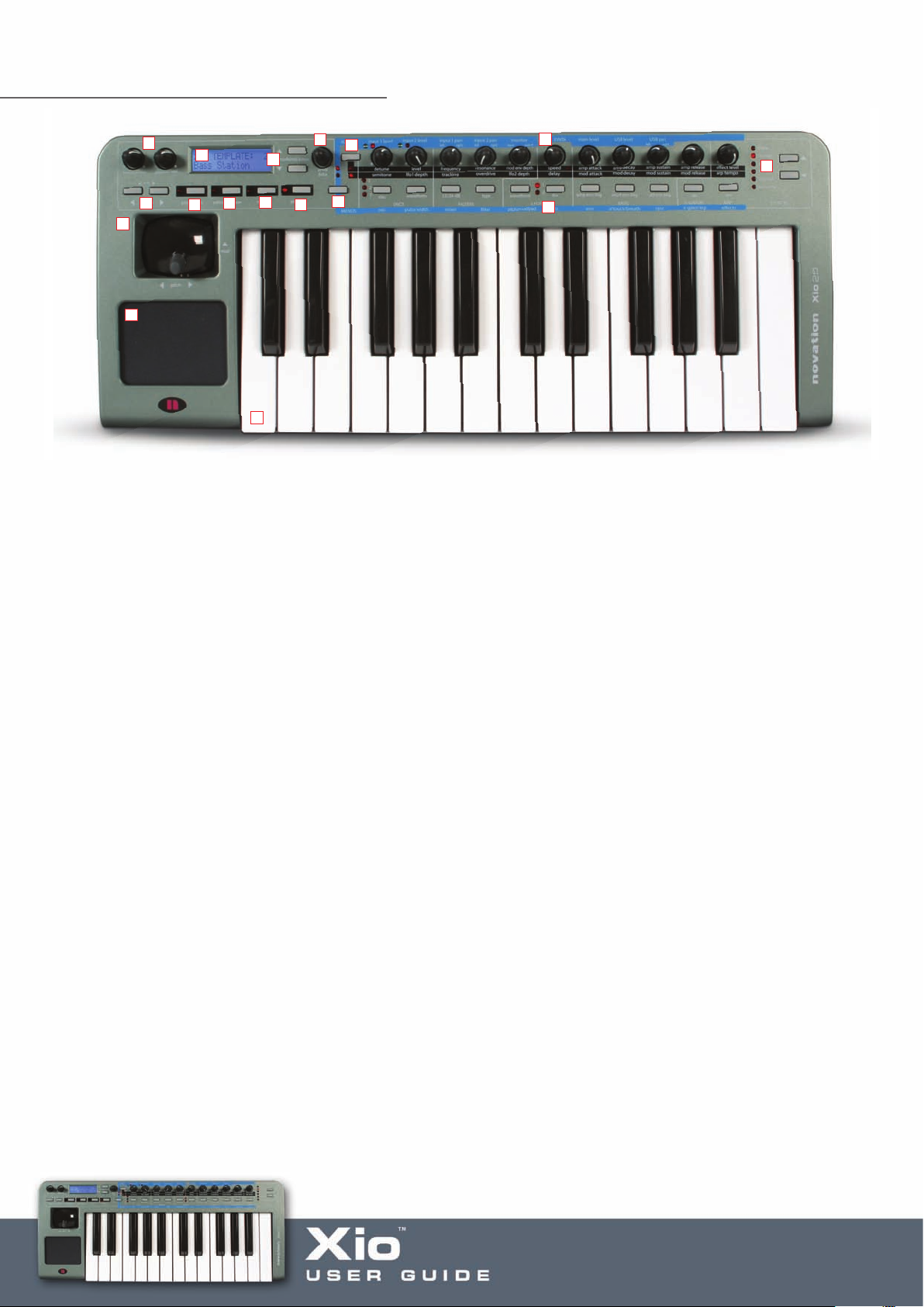
Front Panel Features
2
1
17
16
3
4
8
6
5
5
1
9
11
10
7
13
14
2
1
1. Octave Up/Down buttons – Transpose the keyboard up and down whole octaves when in Synth or
Controller mode. Also move the cursor left and right when naming Synth patches or Templates and
using the X-Gator
2. Line Out and Phones Vol – control the level of the signal at the Line Outputs and Headphones Output
on the Rear Panel, respectively
3. LCD Screen
4. PLAY button – changes between Synth and Controller modes
5. EDIT/COMPARE buttons – calls up EDIT Menus in MIDI Controlling mode. Also compares an edited
patch with saved settings in Synth mode
6. WRITE button – saves settings
7. GLOBAL button – calls up Global Menus (there are two of these in Synth mode)
8. Tmp/bank/page buttons – cycle through Templates in Controller mode and Banks in Synth mode.
Also move through different pages in Edit or Synth menus
9. Prog/data encoder – sends Program Change data (changes the onboard or software synth sound)
in either PLAY mode (in Synth or MIDI controller mode). Also scrolls through options on each menu
or Edit page
10. Menus/Audio button – pr
ess to select a Synth Menu with the buttons (lower LED will light) or pr
ess
and hold to change Audio settings with the knobs (upper LED will light). In MIDI Controlling Mode, the
Menus will be inactive, simply press once to change Audio settings with the knobs (upper LED will light)
11. Gr
oup A/B button – changes the function of the knobs in Synth Mode. Also cycles between Group A
knobs/buttons and Group B knobs/buttons in MIDI Controlling mode
12. 11 buttons – Edit Synth parameters, call up Synth Menus. Also fully assignable buttons in MIDI
olling mode
Contr
13. 11 knobs – Edit Synth parameters. Also fully assignable knobs in MIDI Contr
olling mode
14. Effect Select buttons – select the effect to be edited in synth mode and access preview mode in
both synth and template mode
15. Keyboard
16. X/Y T
ouchpad – Controls Filter (or other parameters) in Synth mode. Also 4 fully assignable controllers
(2 on x-axis and 2 on y-axis) in MIDI Controlling mode
17. Pitch/mod Joystick – Controls pitch-bend and modulation in Synth mode. Also fully assignable joystick
in MIDI Contr
olling mode
Page 5
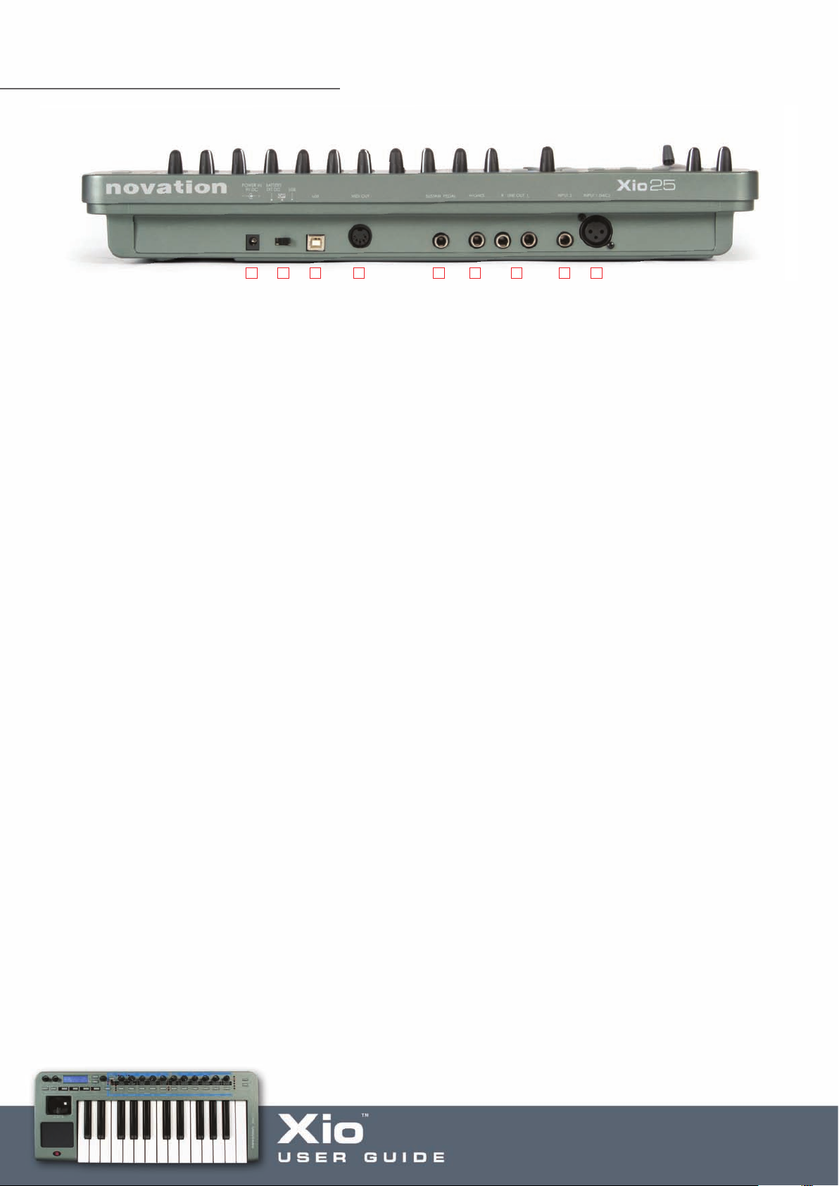
Rear Panel Features
1 2 3 4 5 6 7 8 9
1. PSU input – powers the Xio externally (only required if not powering over USB or with batteries)
2. Power select switch – cycles between PSU/battery, Off and USB power
3. USB Connection – sends/receives Audio and MIDI data, and receives power
4. MIDI Out port – sends MIDI data to external hardware
5. Sustain Pedal Input
6. Headphones Output
7. Unbalanced Line Outputs
8. Unbalanced Line Input
9. XLR Input (mic) – with phantom power
Page 6

Synthesizing
ynth mode is selected with alternate presses of the PLAY button and synth patches are selected using
S
he encoder to the right of the LCD screen, as detailed in the Getting Started Guide. Make sure that the
t
enus/Audio button has not been pressed if attempting to scroll to another sound, as the encoder is used
M
to edit Synth or Audio Menu pages when either of the LEDs above the button are lit. The synth can then be
played using the keyboard, joystick (pitch-bend/modulation) and Touchpad (filter frequency and resonance,
or other parameters set in the 2-D controls Menu).
Editing a Synth Patch
Editing a Synth Patch can be done in a number of ways. The most popular synth parameters are
accessed using the knobs and buttons, which are all labeled to show the parameters being adjusted.
However, as there are only 11 of each, there is a button to change the function of the knobs. With the
top LED illuminated, the knobs modify the upper row of parameters. Pressing the button to the left of the
knobs will then change the knobs function to the lower row of parameters, as follows:
ress the Group A/B button to switch the function of the
P
nobs between the upper and lower row of parameters
k
With the lower LED lit, the bottom row of parameters is active
Furthermore, to access the whole host of other Synth parameters available for editing, a serious of different
Menus can be activated. For example, the oscillator section also has Octave select, portamento control and
so on. To access these, the Osc Menu needs to be activated. This is done by pressing the Menus/Audio
button, so that the lower LED lights, and then pr
Once in Menus mode, press the button above osc (on the blue strip) to activate the Oscillators Menu
Press the Menus/Audio button to activate Menus
mode (so that the bottom LED lights). Do not press
and hold the button as this activates Audio mode
essing the button directly above ‘osc’ as follows:
If the Menus/Audio button is held for too long, making the upper LED light (activating the Audio parameters
across the knobs), then simply press it again to cancel and then once more to make the lower LED light.
Page 7
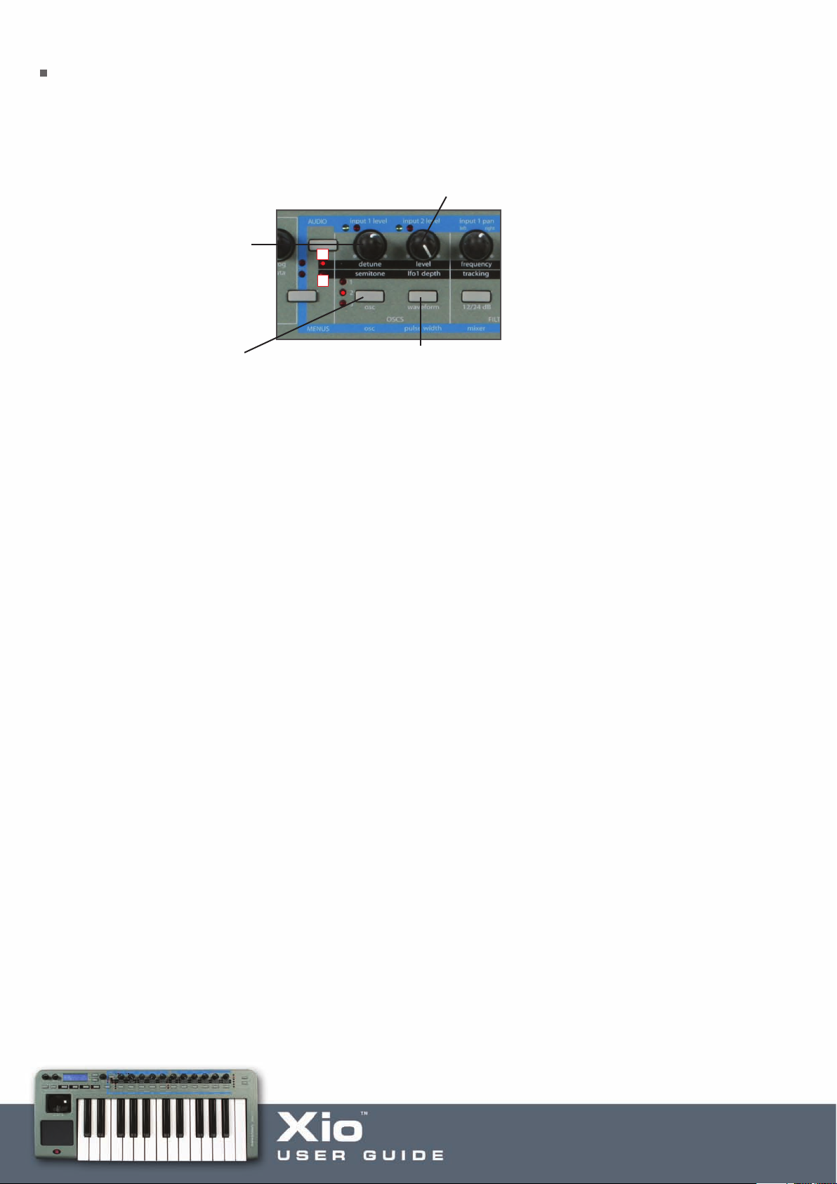
The Oscillators (OSCS) Section/Menu
The Xio has three oscillators, a Noise generator and a Ring modulator. The oscillators are selected using the
‘osc’ button and indicated by the corresponding LEDs. For example, with the 2nd LED lit, the remaining three
controls will adjust Oscillator 2, as follows:
scillator Level when LED 1 is active and LFO 1
O
epth when LED 2 is active
d
scillator Detune (fine tuning) when
O
LED 1 is active and Semitone (coarse
tuning) when LED 2 is active
Press to select Oscillator 1, 2 or 3
(shown by corresponding LED)
The Waveforms available for each oscillator are four traditional waveforms:
SINE, TRIANGLE, SAWTOOTH, SQUARE/PULSE
1
2
ress to change the Oscillator
P
veform
a
W
Four Noise Types:
WHITE NOISE, HP NOISE, BP NOISE, HBP NOISE
And nine digitally sampled waveforms to help construct more traditional instruments or percussive sounds:
ORGAN, HARPSICHORD, ELECPIANO, SLAP BASS, RHOD PIANO, RHOD TINE, WHURLY EP, CLAVINET,
ANA BASS.
emaining Oscillator contr
The r
ols are adjusted in the Oscillator Menu, accessed by pressing the
Menus/Audio button (so that the lower LED lights) followed by the button above ‘osc’. Once in the
Oscillator Menu, use the page up/down buttons next to the LCD screen to cycle through the following
pages, using the data encoder to change the settings for each page:
OSC Por
tamento –
sets the por
tamento (sliding between notes) of the Oscillators to a value between
0 and 127
OSC1ModEnv>Pitch – contr
ols how much the Oscillator 1 pitch is modulated by the Modulation Envelope –
negative and positive values have opposite effects on the pitch (falling then rising and vice versa, respectively)
– set between -64 and +63, where 0 has no effect
OSC2ModEnv>Pitch – controls how much the Oscillator 2 pitch is modulated by the Modulation Envelope
(see above)
Page 8

OSC3ModEnv>Pitch – controls how much the Oscillator 3 pitch is modulated by the Modulation Envelope
(see above)
OSC Osc1 Octave – sets the octave of Oscillator 1 between -1 and +2
OSC Osc2 Octave – sets the octave of Oscillator 2 between -1 and +2
OSC Osc3 Octave – sets the octave of Oscillator 3 between -1 and +2
OSC Poly Mode – sets whether the synth plays monophonically or polyphonically. Choose from the
following options:
Mono – Monophonic (only one note heard at any time)
Mono AG – Monophonic with Auto Glide (automatic portamento when a note is pressed before
the previous one is released)
Poly 1 – Polyphonic 1 allows multiple notes to be played and will stack up repeated presses of
the same note (getting louder and louder)
Poly 2 – Polyphonic 2 allows multiple notes to be played but does not stack up repeated presses
of the same note
OSC Unison – allows multiple voices to be used for each note, e.g. pressing one key makes up to 8 voices
(8 x the signal from the Oscillators) sound rather than just one
OSC Uni Detune – if using the previous Unison option, this page allows the voices to be detuned with
respect to one another. Increase as desired
OSC Vco Drift – sets how much the Oscillators pitch drifts. A good way of emulating old analogue synths
that went out of tune as they heated up
OSC Preglide – applies up to an octave pitch slide up (negative value) or down (positive value) to the note
when a key is pressed. The time taken for the pitch slide is controlled by the OSC Portamento (first page
of this Menu). 127 sets an obvious preglide but at 0 no preglilde will be heard
OSC Porta Mode – sets the type of portamento used. Linear portamento slides between pitches at an
equal rate whereas with exponential, the rate of sweep decreases throughout the duration
OSC Start Phase – allows the precise start point of the oscillator waveform to be determined, useful if
simulating more percussive or plucked sounds for example. Set to OFF, the start point will be random. Set
at 1, the waveform will start at 0 degrees. Each increment will increase the start point by around 3 degrees
OSC 1>2 Sync – allows oscillator 1 and 2 to be synchronised, often creating piercing, metallic effects.
If oscillator 2 has a higher frequency (pitch) then it will take the frequency of oscillator 1 but add interesting
harmonics due to the repeatedly interrupted waveform
Page 9

OSC 23 FM Level – increases the amount that oscillator 3 is Frequency Modulated by oscillator 2, making
the sound more metallic
OSC 2>3 FM ADEnv – increases the amount that the Frequency Modulation (set in the previous option)
is modulated by the AD Envelope (envelope 3 of the Xio – see the Envelopes section for details). This allows a
sound with more interesting harmonics at the start to be created
OSC 2>3 FM Lfo1 – allows the FM set in the previous FM Level option to be modulated by LFO 1
OSC Fixed Note – sets a fixed note (the same pitch) to be played by every key on the Xio. A 0 setting has no
effect. 1-127 set the corresponding MIDI Note value
The remaining Oscillator controls can be found in the Pulse Width and Mixer Menus.
Page 10

The Pulse Width Menu
The Pulse Width Menu allows the pulse width settings for the three oscillators to be set.
This increases/decreases the amount of time the waveform spends in a high or low state, to change
the sound of the waveform. The Pulse Width Menu is accessed by pressing the Menus/Audio button (so
that the lower LED lights) followed by the button above ‘pulse width’. Once in the Pulse Width Menu, use
the page up/down buttons next to the LCD screen to cycle through the following pages, using the data
encoder to change the settings for each page:
PW Osc1 Position – increases/decreases the pulse width of Oscillator 1
PW Osc1 Lfo2>PW – sets the amount that the pulse width of Oscillator 1 is modulated by LFO2
PW Osc1 ModEnv> – sets the amount that the pulse width of Oscillator 1 is modulated by the
Modulation Envelope
PW Osc2 Position – increases/decreases the pulse width of Oscillator 2
PW Osc2 Lfo2>PW – sets the amount that the pulse width of Oscillator 2 is modulated by LFO2
PW Osc2 ModEnv> – sets the amount that the pulse width of Oscillator 2 is modulated by the
Modulation Envelope
PW Osc3 Position – increases/decreases the pulse width of Oscillator 3
PW Osc3 Lfo2>PW – sets the amount that the pulse width of Oscillator 3 is modulated by LFO2
PW Osc3 ModEnv> – sets the amount that the pulse width of Oscillator 3 is modulated by the
Modulation Envelope
Page 11

The Mixer Menu
The Mixer Menu contains the remaining controls for Oscillator levels and mixing. The menu is accessed
by pressing the Menus/Audio button (so that the lower LED lights) followed by the button above ‘mixer’.
Once in the Mixer Menu, use the page up/down buttons next to the LCD screen to cycle through the
following pages, using the data encoder to change the settings for each page:
MIX Output Level – sets the Level of the signal at the output of the Oscillators section
MIX Noise Level – sets the level of the Noise generator in the Oscillators section
MIX Ring12 Level – sets the amount of Ring Modulation between Oscillator 1 and 2. This multiplies the
two waveforms together to create a metallic (or bell-like) effect – the sound of the Daleks!
MIX Lfo1>Osc1 – sets the amount of modulation applied from LFO1 to Oscillator 1
MIX Lfo2>Osc1 – sets the amount of modulation applied from LFO2 to Oscillator 1
MIX Lfo2>Osc2 – sets the amount of modulation applied from LFO2 to Oscillator 2
MIX A/D Env>Osc3 – sets the amount of modulation applied from the AD Envelope to Oscillator 3
MIX Lfo1>Noise – sets the amount of modulation applied from LFO1 to the Noise Generator
Mix Lfo1>Ring12 – sets the amount of modulation applied from LFO1 to the Ring Modulator
MIX Noise Type – sets the Noise Type
WHITE – White Noise
HP – High-pass Noise
BP – Band-pass Noise
HP*BP – High-pass and band-pass (combined effect)
`
Page 12
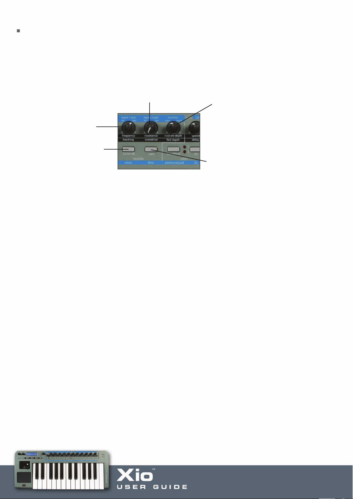
The Filters Section/Menu
The Filters section receives the signal from the Oscillators section (whether that be one oscillator or all
three) and allows that signal to be shaped. The signal can be shaped by a High-pass (where low frequencies
can be removed), Low-pass (where high frequencies can be removed) or Band-pass (where only a small band
of frequencies remains) filter. To select the filter type, press the right hand button, and then adjust the filter
using the remaining controls as follows:
ilter Resonance when LED 1 is active
F
nd Overdrive when LED 2 is active
a
Filter Frequency when LED
1 is active and Tracking
hen LED 2 is active
w
Press to switch between a
2dB and 24dB Filter Slope
1
Frequency – sets the cut-off frequency of the high/low-pass filter or the centre frequency of the band-pass filter
ilter Mod Env Depth when
F
ED 1 is active and LFO 2
L
epth when LED 2 is active
D
Press to switch the Filter
ype between Low-pass,
T
and-pass and High-pass
B
Tracking – sets the amount that the resonance of the filter follows the pitch of the key being pressed. At 0,
the resonance will always have the same character
Resonance – sets the level of resonance (overtones/harmonics) of the filter. Increasing this value adds
character to the sound
Overdrive – increases the filter Overdrive, making the sound richer and more distorted
Mod Env Depth – sets the amount that the Filter Frequency is modulated by the Modulation Envelope in
either direction. A level of 0 will have no effect
LFO2 Depth – sets the amount that the Filter Frequency is modulated by LFO2
The remaining Filter controls are adjusted in the Filter Menu, accessed by pressing the Menus/Audio button
(so that the lower LED lights) followed by the button above ‘filter’. Once in the Filter Menu, use the page
up/down buttons next to the LCD scr
een to cycle thr
ough the following pages, using the data encoder to
change the settings for each page:
T Shape –
FIL
changes the shape of the Filter to incr
ease the amount of distortion and harmonics
FILT Velocity – sets how much velocity controls the Filter Frequency. A negative value makes the frequency
ease with increased velocity, whereas a positive value has the opposite effect. Increase the value in
decr
either direction to increase the effect
FILT Q Normalise – sets the amount of resonance normalisation. At 0, the signal will remain at normal level
when resonance is applied. Increasing the value, makes the signal level reduce in relation to the resonance
Page 13

The LFOs Section/Menu
The LFOs (Low Frequency Oscillators) section allows the settings for either of the LFOs to be edited. LFO1
can be used to modulate the Oscillators and LFO2 the Filter. As there are two LFOs, there is a button for
selecting which one is being controlled, indicated by the active corresponding LED. For example, with LED 2
active, the remaining controls modify the LFO as follows:
FO Speed when LED 1 is active and
L
elay when LED 2 is active
D
ress to switch between LFO 1 and 2
ress to select
P
he LFO waveform
t
Speed – sets the speed of the selected LFO
Delay – sets the delay of the selected LFO (the amount of time before the LFO starts). Useful for
applying vibrato
P
shown by corresponding LEDs)
(
The available waveforms are:
SINE, TRIANGLE, SAWTOOTH, SQUARE, RANDOM S/H (Sample and Hold), QUANT (Quantize) S/H,
CROSSFADE, EXP (Exponential) DECAYS 1-3, ATTACK EXP 1-3, SUST EXPS 1-3, PIANO ENV 1-3, EXP
UPDOWN, CHROMATIC, MAJOR MODES, MAJOR-7, PATTERNS 1-9
The CHROMATIC, MAJOR MODES and MAJOR-7 waveforms can be useful if used for LFO 1. This can be
used to make an Oscillator play a scale by just holding down a key. If doing this, make sure the LFO1 Depth
knob in the Oscillator section is set to + or – 30, so that the scale is in key.
emaining LFO contr
The r
ols are adjusted in the LFO Menu, accessed by pressing the Menus/Audio button
(so that the lower LED lights) followed by the button above ‘lfo’. Once in the LFO Menu, use the page
up/down buttons next to the LCD screen to cycle through the following pages, using the data encoder to
change the settings for each page:
LFO1 V
elocity –
sets the amount that velocity contr
ols LFO1. Setting a positive value makes LFO1 incr
ease
with velocity, whereas setting a negative value has the opposite effect. Increase the value to increase the effect
LFO1 MonoDelT
rig –
allows a dif
ferent LFO effect to be applied when in either Monophonic mode. For
example, if wanting a delayed vibrato only on the first note of a musical phrase, set this to SGL (single).
However, if wanting a delay on every note, set this to MLT (multi)
LFO1 Keysync – synchronises LFO1 to the keyboard. Set to ON, each key press will retrigger the LFO
LFO1 Init Phase – sets a different start point for the LFO waveform when the previous option (Keysync)
is set to ON
Page 14

LFO1 Unipolar – sets whether the LFO modulates in a positive and negative direction (set to OFF) or just
in a positive direction (set to ON)
LFO1 Common – allows the LFO applied to each of the eight voices to be phase locked, creating a more
unnatural sound. Note that with this set to ON, the Keysync page will have no effect. Instead, the Synth
Global Sync option in the Synth Global Menu will override it
LFO1 One-Shot – makes the LFO cycle through its waveform only once and then stop, when set to ON
LFO2 Velocity – sets the amount that velocity controls LFO2. Setting a positive value makes LFO2 increase
with velocity, whereas setting a negative value has the opposite effect. Increase the value to increase the effect
LFO2 MonoDelTrig – allows a different LFO effect to be applied when in either Monophonic mode. For
example, if wanting a delayed vibrato only on the first note of a musical phrase, set this to SGL (single).
However, if wanting a delay on every note, set this to MLT (multi)
…and the same as the remainder of options for LFO1.
Page 15
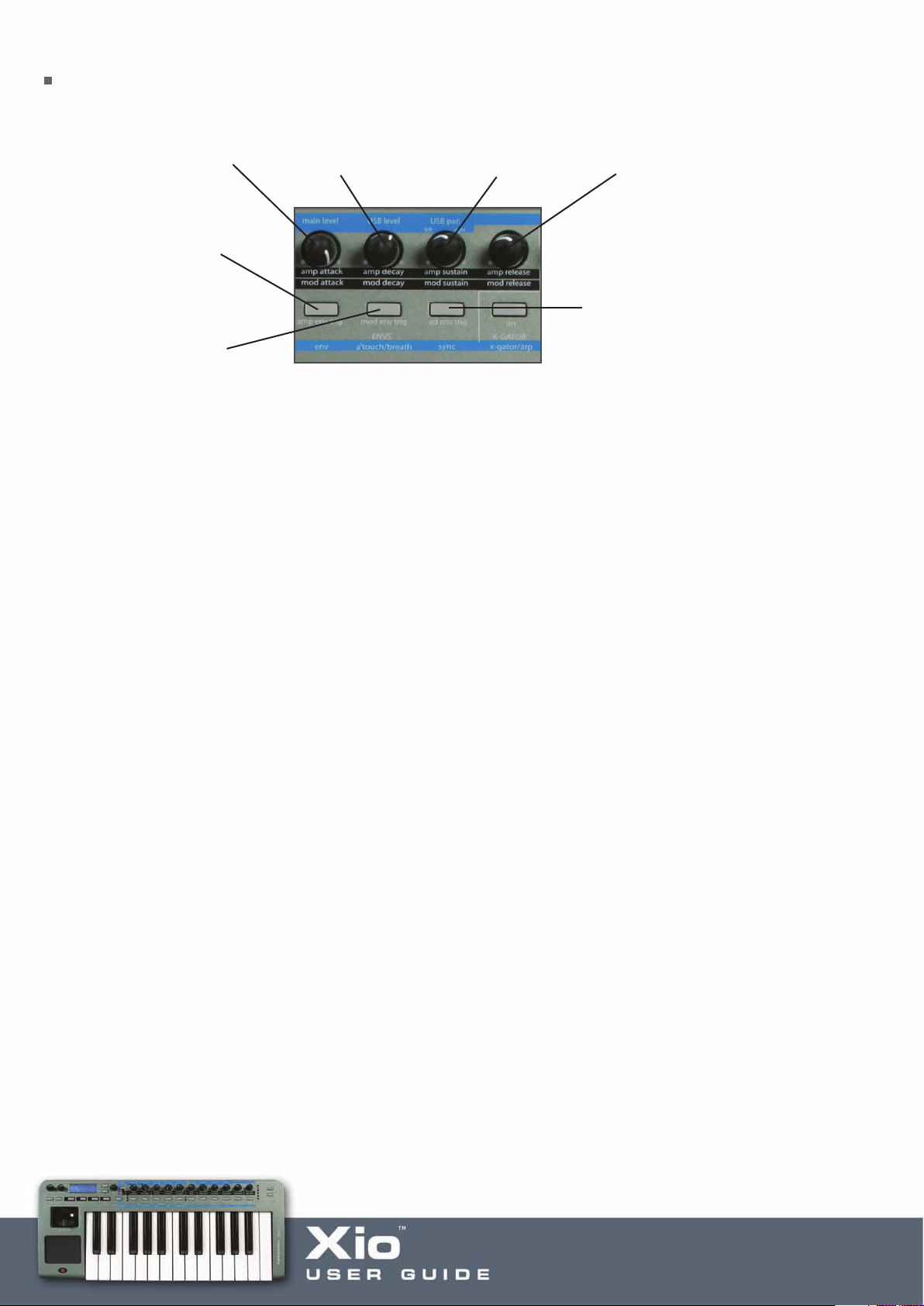
The Envelopes (ENVS) Section/Menu
mp Attack with LED 1
A
ctive and Mod Attack
a
ith LED 2 active
w
hanges the Amp
C
nvelope Trigger (in
E
onophonic mode)
M
Changes the Mod
Envelope Trigger (in
Monophonic mode)
mp Decay with LED 1
A
ctive and Mod Decay
a
ith LED 2 active
w
mp Sustain with LED 1
A
ctive and Mod Sustain
a
ith LED 2 active
w
mp Release with LED 1
A
ctive and Mod Release
a
ith LED 2 active
w
hanges the A/D
C
nvelope Trigger (in
E
onophonic mode)
M
The Envelopes section allows the Amplitude, Modulation and A/D (Attack/Decay) Envelopes to be adjusted.
The Amplitude Envelope is the level of the signal from the Oscillators section over time. The Modulation
Envelope can be used to control three other area of the synth: Oscillator pitch, Oscillator pulse width and
Filter frequency – each with individual settings in the respective sections or menus. The A/D Envelope can
be used to modulate Oscillator 3 and control the FM amount. The options for AMP and MOD envelopes are
as follows:
Attack – sets the amount of time taken for the envelope to reach maximum level
Decay – sets the amount of time taken for the envelope to fall to the sustain level after maximum level
has been reached
Sustain – sets the level when a note is held down after the decay period
Release – sets the amount of time taken for the level to decrease when a note is released
The three buttons can be used to set the Trigger of each envelope. This sets whether or not an envelope is
triggered with every key press, and is only applicable when the Oscillator section is in Monophonic Mode (see
the Oscillators section for details). For example, you may want the AMP envelope to only be triggered on the
first note of a legato phrase (so the phrase gets progressively quieter) but the MOD envelope to be triggered
on ever
y key pr
ess; in this case, the AMP ENV TRIG should be set to SGL (Single) and the MOD ENV TRIG to
MLT (Multi). Press each button to alternate between these states.
emaining Envelope controls are adjusted in the Envelopes Menu, accessed by pressing the
The r
Menus/Audio button (so that the lower LED lights) followed by the button above ‘env’. Once in the Envelopes
Menu, use the page up/down buttons next to the LCD screen to cycle through the following pages, using
the data encoder to change the settings for each page:
ENV Amp Velocity – sets the amount that velocity effects the volume of the sound. Setting a negative value
has the opposite effect (decreasing when pressed harder)
Page 16

ENV Mod Velocity – sets the amount that velocity effects the level of the Modulation Envelope. Setting
a negative value has the opposite effect (decreases when pressed harder)
ENV A/D Velocity – sets the amount that velocity effects the level of the A/D Envelope (Envelope 3).
Setting a negative value has the opposite effect (decreasing when pressed harder)
ENV A/D Attack – sets the Attack time of the A/D (Attack/Decay) Envelope
ENV A/D Decay – sets the Decay time of the A/D (Attack/Decay) Envelope
Page 17

The X-Gator Menu
The X-Gator is turned On and Off, as well as latched (by pressing and holding), using the button above
X-GATOR as follows:
ress to turn the X-Gator On and Off, press and
P
old to latch the X-Gator
h
The X-Gator is a patch programmer that literally gates the synth sound over time to allow patterns to be
created. These patterns are set in a 32-step sequencer in the X-Gator Menu, where the remaining X-Gator
parameters can be edited. The X-Gator Menu is accessed by pressing the Menus/Audio button (so that the
lower LED lights) followed by the button above ‘x-gator/arp’. Pressing this button, alternates between the
X-Gator and Arp Menus so make sur
Menu. Once in the X-Gator Menu, use the page up/down buttons next to the LCD screen to cycle through
the following pages, using the data encoder to change the settings for each page:
e you can see one of the pages below to ensure you are in the correct
Page 1 allows the X-Gator patter
n to be set:
Use the x-g buttons (also the Octave buttons) on the 6 to move the cursor through the 32 steps and the
encoder to increase/decrease the level of each step.
XGATE Latch – sets the X-Gator Latch to ON or OFF
XGATE Mode – sets the mode of the X-Gator
MONO 16 – repeats the first 16 steps
MONO-ALT 1 – repeats all 32 steps
MONO-ALT 2 – plays the first 16 steps twice then plays the next 16 steps twice, then repeats
STEREO 16 – pans the first 16 steps (repeated)
ST-SWAP 1 – pans the first 16 steps in an alternating sequence - left then right etc. (repeated)
ST-SWAP 2 – pans the first 16 steps in a different alternating sequence (repeated)
Page 18

XGATE Level – sets the level of the X-Gator
XGATE Edge – sets the edge of the X-Gator. Increase to soften and make the effect smoother
XGATE Decay – sets the decay time of each step. Below 64 shortens and above 64 lengthens
XGATE Delay – increases/decreases the amount of delay on the X-Gator
XGATE Keysync – synchronises the X-Gator start with each key press. Set to OFF to make the X-Gator run freely
The X-Gator tempo can be set in the Sync Menu (see the Sync Menu section for details).
Page 19
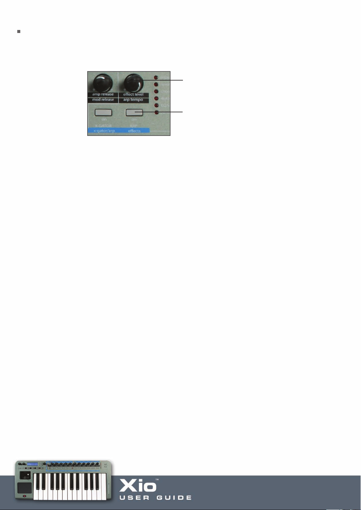
The Arpeggiator Section/Menu
The Arpeggiator controls allow the Arpeggiator to be turned on and off, latched (by pressing and holding)
and the speed to be set, as follows:
hange the Arp Speed when LED 2 is active
C
ress to turn the Arp On and Off,
P
ress and hold to latch the Arp
p
Note that the speed will be overridden by the Arp tempo set in the Sync Menu (see the Sync Menu section
for details) if the Xio is synchronising to MIDI clock (received over USB). The Xio will synchronise
automatically unless the MIDI Clock Sync option is changed in the Synth Global Menu (see the Synth Global
Menu section for details).
The remaining Arpeggiator controls are adjusted in the Arpeggiator Menu. The Arpeggiator Menu is
accessed by pressing the Menus/Audio button (so that the lower LED lights) followed by the button above
‘x-gator/arp’. Pressing this button, alternates between the X-Gator and Arp Menus so make sure you can
see one of the pages below to ensure you are in the correct Menu. Once in the ArpMenu, use the page
up/down buttons next to the LCD screen to cycle through the following pages, using the data encoder to
change the settings for each page:
ARP Mode – sets the Arpeggiator pattern to various up and down combinations (UP, DOWN, UP-DOWN 1,
UP-DOWN 2), as played (PLAYED), randomly (RANDOM) or a chord of any notes pressed (CHORD)
ARP Latch – turns the Arpeggiator latch ON and OFF. Setting to ON makes the Arpeggiator sustain after
a note is pr
essed
ARP Octaves – sets the number of octaves that the arpeggiator spans across from 1 to 4
ARP Pattern – sets the Arpeggiator to play a rhythmic pattern. Choose between 32 options
ARP Pattern Vel – sets the velocity of notes within the Arpeggiator pattern to follow the velocity of notes
being played. Set to OFF to make the Arpeggiator pattern follow preset velocities
ARP Gate Time – sets the gate time (duration) of Arp notes. Set to a small value to make the notes more
staccato. Increase to create a legato effect
ARP Keysync – synchronises the Arp to each note press
ARP Notes – allows the Arpeggiator MIDI data (Note On/Off messages) to be sent to a number of
destinations: INT (Internal Sound Engine), EXT (MIDI Output) or I+E (both)
Page 20
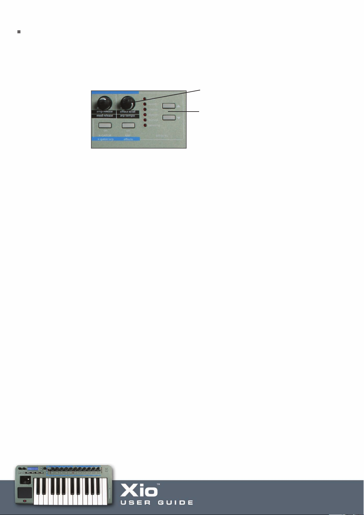
The Effects Section/Menu
The Effects controls are used to apply any or all of the Effects (Delay, Reverb, Chorus/Phaser, Distortion,
EQ/Vol and Panning) to the Synthesizer. The effect select buttons are also used to access the preview mode
where it is possible to see the current value of any parameter without changing a parameter's value - see
the preview mode section in this user guide.
Increase the Effect Level with LED 1 active
Press to select the Effect
shown by corresponding LED)
(
Delay – adds a delayed version of the signal (like an echo) a certain time after the original. This can
be made to repeat many times if required (determined by the Feedback level)
Reverb – sets the amount of reverberant (reflected) sound to simulate an environment like a performance
hall or small chamber
Chorus/Phaser – adds a repetition of the original signal with a variable delay to create the effect of
multiple voices (hence chorus). The Phaser adds a repetition of the original signal with variable phase
to create a swirling effect
Distortion – adds distortion (loud overtones) to the signal to create a heavier sound
EQ/Vol – increases/decreases the level of Low (as default), Mid or High (within the Menu) Frequencies.
Also sets the MIDI Volume (within the Menu)
Panning – allows the sound to bounce fr
om left to right. Incr
easing the level of this Effect increases the
amount of stereo panning (PAN Mod Depth)
The remaining parameters for each effect can be accessed in each of the Effects’ Menus. Note that there
are 6 different Effects’ Menus, all accessed in the same way but dependent on what Effect LED is active on
the Xio. For example, if wanting to edit the r
emaining parameters for Delay
, use the Effect Select buttons
(shown above) to select Delay then press the Menus/Audio button (so that the lower LED lights) followed by
the button above ‘effects’. Once in the Delay (Effects) Menu, use the page up/down buttons next to the LCD
een to cycle through the following pages, using the data encoder to change the settings for each page:
scr
DEL Delay Time – sets the length of the Delay
DEL Feedback – sets the amount of Feedback (the length of time for which the Delay continues)
DEL Stereo Width – sets the stereo width of the Delay
DEL L/R Ratio – sets the delay ratio between Left and Right channels
Page 21

Whilst in the Effects Menu, you can move to another Effect simply by selecting it with the Effect Select
buttons shown in the diagram above. For example, to access the Reverb parameters from the Delay Menu,
press the downward Effect Select button so that the Reverb LED lights. Now, use the page up/down buttons
next to the LCD screen to cycle through the following pages:
REV Type – sets the type of Reverb between: Chamber, S-Room (Small Room), L-Room (Large Room), S-Hall
(Small Hall), L-Hall (Large Hall), G-Hall (Giant Hall)
REV Decay Time – sets the amount of time taken for the Reverb to decay
To view the Chorus parameters, press the downward Effect Select button once more so that the Chorus
LED is active. Once in the Chorus (Effects) Menu, use the page up/down buttons next to the LCD screen
to cycle through the following pages, using the data encoder to change the settings for each page:
CHOR Type – selects either CHORUS or PHASER mode
CHOR Mod Rate – sets the rate of Chorus modulation
CHOR Mod Depth – sets the amount of Chorus modulation
CHOR Centre Posn – shifts the centre point of the Chorus modulation between either extreme (dependent
on the previous Depth setting)
CHOR Feedback – sets the amount of Feedback. It is normally advisable to have low levels of feedback when
in Chorus mode and higher levels in Phaser mode
CHOR Init Posn – sets the Chorus start point to Left, Right, Middle or Off (where there is no defined
start point)
To view the Distortion parameters, press the downward Effect Select button once more so that the Distort
LED is active. Once in the Distortion (Effects) Menu, use the page up/down buttons next to the LCD screen
to cycle through the following pages, using the data encoder to change the settings for each page:
DIST Compensate – compensates for/decreases the level overload caused by the Distortion
DIST Output Lvl – compensation can cause the overall level to be low so this page allows the level to
be increased
To view the EQ/Vol parameters, press the downward Effect Select button once more so that the EQ/Vol
LED is active. Once in the EQ/Vol (Effects) Menu, use the page up/down buttons next to the LCD screen
to cycle through the following pages, using the data encoder to change the settings for each page:
EQ Mid – increases/decreases the level of Mid Frequencies
EQ Treble – increases/decreases the level of High Frequencies
Page 22

MIDI Volume – sets the MIDI Volume from 0 to 127
To view the Panning parameters, press the downward Effect Select button once more so that the Panning
LED is active. Once in the Panning (Effects) Menu, use the page up/down buttons next to the LCD screen
to cycle through the following pages, using the data encoder to change the settings for each page:
PAN Position – sets the permanent pan position from fully left (-64) to fully right (+63)
PAN Mod Rate – sets the rate at which the signal oscillates between left and right extremes
PAN Init Posn – sets the start point of the signal to Left, Middle or Right. Setting to OFF makes the signal
begin in a random position, unless no panning modulation is occurring
Delay, Chorus and Panning effects can all be synchronised to MIDI clock from the sequencer (received
over USB). This is set up in the Sync Menu (see the Sync Menu section for details).
Page 23

The 2-D controls Menu (Xpression pad and stick)
The 2-D controls Menu allows the function of the Xpression pad and joystick to be edited. All preset synth
patches have the Xpression pad set up on the filter frequency (x-axis) and resonance (y-axis) but this can be
changed within this Menu. Similarly, the joystick horizontal function and vertical function can be set.
To access the 2-D controls Menu, press the Menus/Audio button (so that the lower LED lights) followed
by the button above ‘pitch/mod/pad’. Once in the 2-D Controls Menu, use the page up/down buttons next
to the LCD screen to cycle through the following pages, using the data encoder to change the settings for
each page:
BW Osc1 Bend – sets the amount of pitch bend across the joystick (horizontal motion) for oscillator 1
between -12 and +12 semitones
BW Osc2 Bend – sets the amount of pitch bend across the joystick (horizontal motion) for oscillator 2
between -12 and +12 semitones
BW Osc3 Bend – sets the amount of pitch bend across the joystick (horizontal motion) for oscillator 3
between -12 and +12 semitones
MW Pitch Direct – increases/decreases the amount of Oscillator pitch variation in semitones when
modulation (joystick vertical motion) is increased
MW Pitch Mod – sets the amount that modulation (joystick vertical motion) results in LFO1 modulating
Oscillator pitch
MW Filter Freq – sets the amount that modulation (joystick vertical motion) affects the filter frequency.
A negative value decreases the filter frequency as modulation is increased and a positive value increases it
MW Filter Freq Mod – sets the amount that modulation (joystick vertical motion) results in LFO2 modulating
the filter fr
MW Output Level – allows modulation (joystick vertical motion) to control the overall output level. A positive
value makes the volume increase with modulation and a negative value makes the volume decrease
MW Delay Level – allows modulation to contr
increase the send level and a negative one will decrease it
MW Reverb Level – allows modulation to contr
increase the send level and a negative one will decrease it
equency
ol the send level to the Delay ef
ol the send level to the Reverb effect. A positive value will
fect. A positive value will
MW Chor
increase the send level and a negative one will decrease it
MW Distort Level – allows modulation to control the send level to the Distortion effect. A positive value will
increase the send level and a negative one will decrease it
us Level –
allows modulation to contr
ol the send level to the Chorus effect. A positive value will
Page 24

Touchpad X Type – sets the Action of the Touchpad to: No Spring (value remains at the last contact point),
Spring Left (value jumps to the extreme left value when contact with the pad is ended), Spring Centre (value
jumps to the centre value when contact with the pad is ended)
Touchpad Y Type – sets the Action of the Touchpad to: No Spring (value remains at the last contact point),
Spring Down (value jumps to the bottom value when contact with the pad is ended), Spring Centre (value
jumps to the centre value when contact with the pad is ended)
Touchpad X Assign – sets the parameter controlled by the Touchpad x-axis between:
OFF – no control
BEND – pitch-bend
MOD - modulation
AFTERTOUCH - aftertouch
BREATH - breath
FILTER FREQ – filter frequency
FILTER RES – filter resonance
LFO1 RATE – speed of LFO1
LFO2 RATE – speed of LFO2
LFO2>FIL
Touchpad Y Assign – sets the parameter controlled by the Touchpad y-axis between the identical
parameters above
TF –
amount that LFO2 modulates the Filter Fr
equency
Page 25

The Aftertouch And Breath Menu
This Menu allows the Aftertouch and Breath settings to be edited. Although the Xio keyboard does
not have Aftertouch, it can be assigned to the Touchpad to allow effects to be created. The Breath settings
determine how the Xio will respond to Breath (CC2) Messages, normally received from a MIDI wind
instrument. Again, Breath can be assigned to either Touchpad axis and both Breath and Aftertouch
messages can be received over USB.
To access the Aftertouch and Breath Menu, press the Menus/Audio button (so that the lower LED lights)
followed by the button above ‘a’touch/breath’. Once in the Aftertouch and Breath Menu, use the page
up/down buttons next to the LCD screen to cycle through the following pages, using the data encoder to
change the settings for each page:
AT Pitch Direct – increases/decreases the amount of Oscillator pitch variation in semitones when
aftertouch is applied
AT Pitch Mod – sets the amount that aftertouch results in LFO1 modulating Oscillator pitch
AT Filter Freq – sets the amount that aftertouch affects the filter frequency. A negative value decreases
the filter frequency as aftertouch is increased and a positive value increases it
AT Filter Freq Mod – sets the amount that aftertouch results in LFO2 modulating the filter frequency
AT Output Level – allows aftertouch to control the overall output level. A positive value makes the volume
increase with modulation and a negative value makes the volume decrease
BR Pitch Direct – increases/decreases the amount of Oscillator pitch variation in semitones when
breath is applied
BR Pitch Mod – sets the amount that breath results in LFO1 modulating Oscillator pitch
…followed by the remaining options for Aftertouch.
Page 26

The Sync Menu
The Sync Menu allows the X-Gator, Arpeggiator, LFOs and Effects to all be synchronised to MIDI clock. This
can be an external MIDI clock (from a sequencer for example) or the internal MIDI clock of the Xio, the
speed of which is determined by the Arp Tempo knob. The Xio default settings mean that the keyboard will
automatically lock to incoming MIDI clock. To change this setting, go to the Synth Global Menu (see the next
section for details).
To access the Sync Menu, press the Menus/Audio button (so that the lower LED lights) followed by the
button above ‘sync’. Once in the Sync Menu, use the page up/down buttons next to the LCD screen to cycle
through the following pages, using the data encoder to change the settings for each page:
SYNC Xgate Tempo – sets a tempo for the X-Gator (relative to the MIDI clock) to fractions of 1 bar,
beginning at a 64th. On this page, T stands for Triplet and D for Dotted, allowing two more syncopated
rhythmic options
SYNC Arp Tempo – sets a tempo for the Arpeggiator (relative to the MIDI clock) to fractions of 1 bar,
beginning at a 32nd. On this page, T stands for Triplet and D for Dotted, allowing two more syncopated
rhythmic options
SYNC Lfo1 Delay – sets a tempo for LFO1 Delay (relative to the MIDI clock) to fractions or multiples
of 1 bar, beginning at a 32nd. On this page, T stands for Triplet and D for Dotted, allowing two more
syncopated rhythmic options
SYNC Lfo1 Speed – sets a tempo for LFO1 Speed (relative to the MIDI clock) to fractions or multiples of 1
bar, beginning at a 32nd. On this page, T stands for Triplet and D for Dotted, allowing two more syncopated
rhythmic options
SYNC Lfo2 Delay – sets a tempo for LFO2 Delay (relative to the MIDI clock) to fractions or multiples of
1 bar, beginning at a 32nd. On this page, T stands for Triplet and D for Dotted, allowing two more
syncopated rhythmic options
SYNC Lfo2 Speed – sets a tempo for LFO2 Speed (relative to the MIDI clock) to fractions or multiples of 1
bar, beginning at a 32nd. On this page, T stands for Triplet and D for Dotted, allowing two more syncopated
rhythmic options
SYNC Delay Time – sets a tempo for the Delay effect (relative to the MIDI clock) to fractions or multiples
of 1 bar, beginning at a 32nd. On this page, T stands for Triplet and D for Dotted, allowing two more
syncopated rhythmic options
SYNC Chor Rate – sets a tempo for the Chorus effect (relative to the MIDI clock) to fractions or multiples
of 1 bar, beginning at a 32nd. On this page, T stands for Triplet and D for Dotted, allowing two more
syncopated rhythmic options
SYNC Pan Rate – sets a tempo for Panning (relative to the MIDI clock) to fractions or multiples of 1 bar,
beginning at a 32nd. On this page, T stands for Triplet and D for Dotted, allowing two more syncopated
rhythmic options
Page 27

Global Menu in Synth Mode
There are two Global Menus in Synth Mode, accessed by alternate presses of the GLOBAL button. The first
is the standard Global Menu, accessed from Synth or MIDI Controlling Mode, and the second is the Synth
Global Menu, just accessed whilst in Synth Mode. Within the Synth Global Menu, the general Synth settings,
such as MIDI channel, port routing and transposition, can all be modified.
To access the Synth Global Menu, press the GLOBAL button twice, ensuring that one of the options below
is displayed. Then, once in the Synth Global Menu, use the page up/down buttons next to the LCD screen
to cycle through the following pages, using the data encoder to change the settings for each page:
Synth Midi Chan – sets the MIDI channel that the synth responds to. This defaults to 16
Synth Out Ports – sets the port routing for synth MIDI data to the USB, MIDI Out, both or neither
Def SampleRate – sets the sample rate of synthesizer audio transmitted over USB to 44.1 or 48kHz
(dependant on your session)
Synth Tune Cents – allows fine tuning of the synthesizer. At +63, the pitch will be a semitone above the
played note. At -64, the pitch will be a semitone below. At 0, the pitch will be unaffected
Synth Transpose – transposes the synthesizer pitch in whole semitones. Positive values increases, negative
values decreases
Synth Glob Sync – allows the synthesizer (effects etc.) to be synchronised to the first note pressed after
notes are released, a program change message or a song start message. This means that effects can
have their start time linked to the start of a song for stunning effects
Synth Vel Curve – sets the Velocity Curve of the synthesizer to a curve from 1-7 (see the Template Common
section for Velociy Curve Graphs) or to a constant value between 8 and 127
Synth Vel Resp – sets the response of the Velocity to SOFT (where softer playing will create low and high
velocities) or HARD (where harder playing will be required to create the same dynamic range)
Syn Local Cntrl – determines whether the Xio keys and controls affect the onboard synthesizer. Useful if
wanting to use the synth to send MIDI data but not be played whilst doing so. However
modes mean that it’s probably better to remain in MIDI controlling mode if wanting to utilise the full potential
of the keyboard
Midi Clock Sync – sets the MIDI clock to AUTO (automatic synchronisation to MIDI clock received over USB),
INT (Internal MIDI clock) or EXT (External MIDI clock)
, the Xio’
s hybrid
Synth Mode (Input) Mute - allows either or both of the Inputs to be muted when in Synth Mode
Page 28

Routing MIDI to and from the Synth
The Xio is an incredibly flexible instrument that can be used to send MIDI data to a sequencer or external
hardware, and also receive MIDI data and be played simultaneously. (For more information about playing the
Synth in MIDI Controlling mode, read the corresponding Hybrid mode section of this User Guide.)
Although it is advised to use Hybrid mode (using the Synth whilst in MIDI Controlling mode) if wanting to
send MIDI data from the Xio keys and controls whilst the sequencer is playing the keyboard’s Synth,
it can be done whilst in Synth Mode. Firstly, make sure that the sequencer track sending MIDI Data is
transmitting on channel 16. This is the default channel in the Synth Global Menu. Now, turn Local Control
off by pressing the GLOBAL button twice to access the Synth Global Menu and scrolling to the relevant
page, as outlined in the previous section.
With these settings, the keyboard’s Synth will respond to MIDI information from the sequencer but not
to its own keys and controls. To change the port routing that the MIDI data from the keyboard’s keys and
controls is sent to (e.g. if wanting to send it to external hardware and not the sequencer or vice versa),
scroll to the Synth Out Ports page within the Synth Global Menu (see the previous section for details).
Page 29
Saving a Synth Patch
A Synth Patch can be saved by pressing the WRITE button in Synth Mode. Doing so will activate the following page:
Patch Name
To Program XXX
Patch Name is the name of the currently selected Synth Sound and XXX is the number (from 100-299) of
that Patch. Simply rotate the data encoder to select a different Patch number if required, then press WRITE
again to save the current Patch to that onboard memory slot.
If after the first press of the WRITE button, the screen shows:
MEMORY
PROTECTED
(The message will appear temporarily and then the Xio will return to PLAY mode.)
Then the Xio GLOBAL setting has activated Memory Protect, which will mean onboard memory
cannot be overwritten. (See the GLOBAL Menu section for details.)
Providing Memory Protect (in the GLOBAL menu) is off, once the WRITE button has been pressed for
a second time, the LCD display will show:
Program ReName?
Patch Name
The name of the Template can now be modified if required by using the Menus/Audio button to change the
character type from 0-9, A-Z, a-z or various punctuation, the data encoder to change the character and the
Octave up/down buttons to move the cursor
Pressing the WRITE button a third time will show the following (final) screen temporarily, before returning to
EDIT mode:
.
PROGRAM SAVED
It is possible to abort the WRITE procedure at any stage by pressing another Mode/Menu button (e.g.
PLAY, EDIT, GLOBAL).
Page 30

Restoring a Synth Patch
If a Synth patch has been edited on the Xio, the COMPARE buttons will flash to indicate that the sound has
changed. To listen to the saved preset, press and hold the COMPARE button. If the saved preset is preferred then
it can be restored simply by using the data encoder to scroll to another onboard sound and then to return to that
patch, e.g. if editing patch 256, then scroll to 255 then back to 256 to restore the saved settings. Make sure
that the Menus/Audio button has not been pressed if attempting to scroll to another sound, as the encoder is
used to edit Synth or Audio Menu pages when either of the LEDs above the button are lit.
Synth Levels
The level of the Synth has numerous controls, depending on the position in the signal path. In addition to the
overall level controls for the Heaphones and Line Outputs, there are separate controls to set the level of the Synth
across the analogue Outputs and over USB. These controls are knobs 6-9 (when in AUDIO/SYNTH mode):
button to activate Synth Levels mode
across knobs 7-9 (upper LED will light)
Main Synth Level Synth USB Level Synth USB panningPress and hold the Menus/Audio
To activate the parameters across the knobs, press and hold the Menus/Audio button so that the top LED lights;
pressing and releasing the button, so that the bottom LED lights, activates the Synth Menus mode so will not
fice. Once in AUDIO/SYNTH mode, the knobs can be used to set the Main Level, that sent to USB (for
suf
recording) and the stereo USB panning.
Page 31
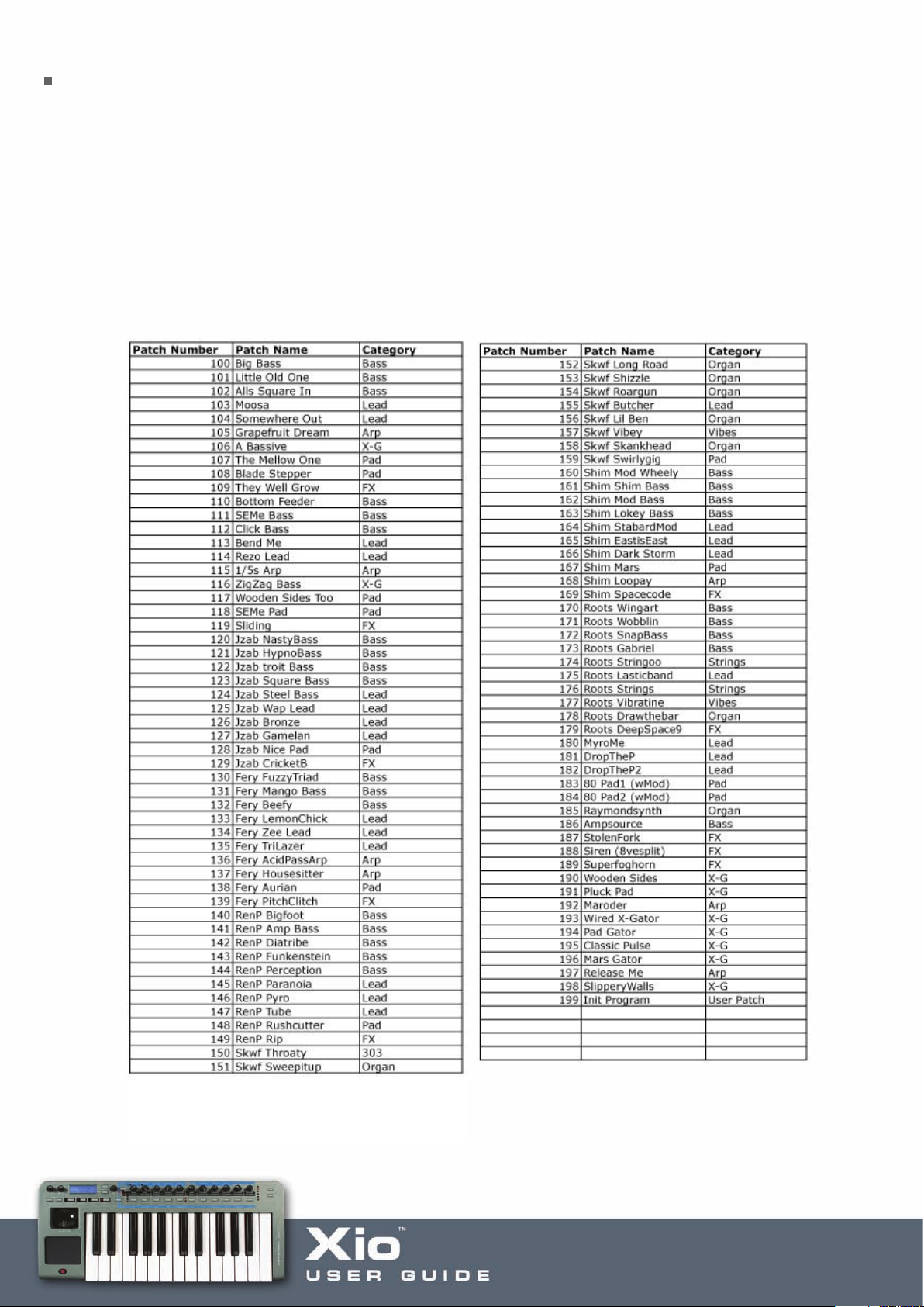
Onboard Programs (Synth Patches)
The two sound banks on the Xio, each with 100 original, fantastic patches, are ordered in different ways.
The first bank contains sounds from a US programmer Kelvin Russel, as well as all of the patches from the six
highly-acclaimed artists and producers. Throughout both banks are numerous cutting edge patches from
talented producers working at Novation Headquarters.
Bank 1
Bank 1 has 20 assorted sounds from Kelvin Russel, 10 from James Zabiela, 10 from Ferry Corsten, 10 from
Rennie Pilgrem, 10 from Skeewiff, 10 from Shimon/Ram Records,10 from Roots Manuva, 10 retro sounds,
9 X-Gator/Arp patches and 1 single sawtooth wave on oscillator 1 (for creating patches), in that order:
Page 32
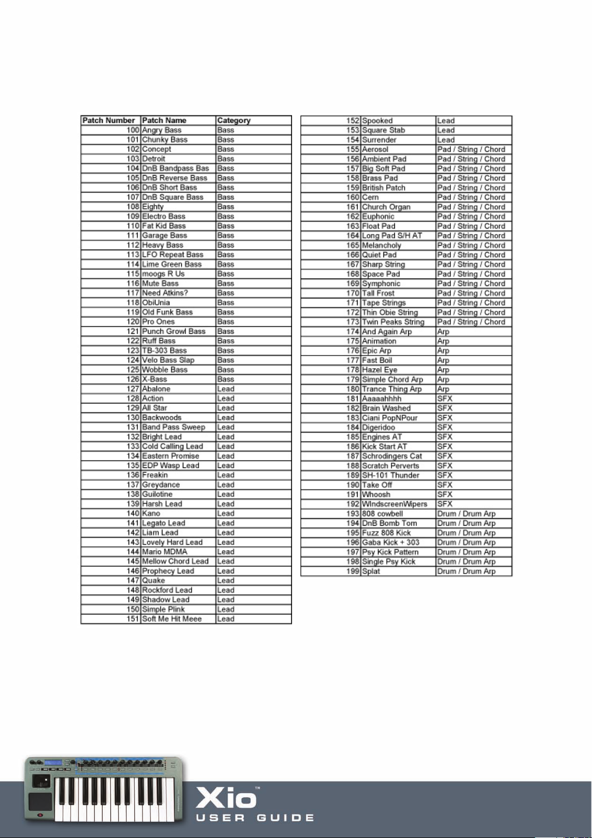
Bank 2
Bank 2 has a variety of fresh, powerful sounds, arranged in groups to help with composition, e.g. basses all
together, then leads etc.:
Page 33

MIDI Controlling
Selecting/Using a Template
hen MIDI Controlling mode is initially accessed by pressing the PLAY button, the Xio is in
W
TEMPLATE SELECT mode. The display shows the Template’s name and location in this mode, for example:
XIO TEMPLATE:5
FM7
When a knob/button is rotated/pressed, the changing value of MIDI data assigned to it is displayed
temporarily. For example, if Filter Frequency is assigned to the Knob 1 on Continuous Controller number
105 and that knob is rotated then the following will be briefly shown:
Filter Frequency
065 CC105
(065 will not be a fixed value but will change as the knob is rotated.) Once the value has been set and
the knob/button has been released, the currently selected Template reappears after an amount of time
set within the GLOBAL menu. See the GLOBAL Menu section for details.
Page 34

GROUP A/B Button
Press to switch between Group A and B (this means that you have
double the amount of assignable controls available in each Template)
Although there are only 11 knobs and 11 buttons visible on the Xio, there are in actual fact double
that amount available for edit; two Groups (A and B) mean that there are a total of 22 knobs and 22 buttons
accessible. The Xio will default to Group A, as indicated by the top LED being illuminated. Simply press
the GROUP A/B button to activate the second group of knobs/buttons (the LED below will light to show that
Group B is activated), all 11 knobs and all 11 buttons will now have a different function (in preset Templates)
or can now be assigned completely different parameters within the User Template (if building your own).
Display of X / Y TouchPad controls
In PLAY mode, when the touchpad is pressed the display will show:
X1 = XXX Y1 = XXX
X2 = XXX Y2 = XXX
XXX is the actual value being sent. For example, if the high value has been set to 10 and the low value 3,
then a value between 3 and 10 will appear. XXX will show ‘Off’ if that control within the Touchpad is not activated.
Both the X-axis (horizontal) and Y-axis (vertical) can be assigned up to two parameters, shown by X1/X2 and
Y1/Y2. For example, filter fr
delay feedback are both assigned to the Y-axis. Alternatively, just one control could be assigned to one axis if a
simpler function is required.
equency and delay time could both be set to the X-axis, whilst filter r
esonance and
Page 35

Display of Sustain Pedal
If a Sustain pedal is connected to the Xio’s rear panel input and activated during PLAY mode, the display
will show:
Sustain Pedal
XXX CC64
XXX shows ‘On’ if the MIDI value sent is 64 or ‘Off’, if the MIDI value sent is less than 64.
Editing a Template
This mode is used to either edit individual controls within one of the 16 onboard MIDI Templates or change the
common Template parameters (the settings across all Templates) such as the velocity curve that the keyboard
is set to. The two different EDIT Mode menus are accessed by either the first or second press of the EDIT button.
Pressing the EDIT button once, whereby the LED to the left of the button will illuminate constantly, activates the
individual Template Edit menu. Pressing the EDIT button twice, making the LED to the left of the button flash,
accesses the Common Template Edit menu.
To view all the Template controls simultaneously and edit them quickly and easily on your computer, use
the separate Template Editor application, which can be downloaded for free from www.novationmusic.com.
Page 36

Editing an individual onboard Template
After the EDIT button has been pressed once to activate the Template Individual Edit Menu (the LED to the left of
the button will be illuminated continuously), the MIDI data assigned to Knob 1 (in Group A or B, depending on which
is selected) will be displayed on the LCD screen. Pressing/rotating/moving any of the Xio’s controls will call up the
MIDI data for that particular control for editing on the LCD screen, by stepping through the pages of the Template
Individual Edit Menu. The first option in the Template Individual Edit Menu is the type of MIDI data that the control
has assigned to it. So, if the button/knob is set to a Continuous Controller number then the screen shows:
Control Type:
XXX CC
The types of MIDI data available are:
CC Continuous Controller. Any controller number can be used, however the MIDI standard
defines controller numbers 0, 6, 32, 38, 96, 97, 98, 99, 100, 101 & 120-127 for
specific specialised purposes. These values should not be used unless the consequences
upon the connected MIDI device are appreciated.
NRPN Non-registered Parameter Number.
RPN Registered Parameter Number.
MMC MIDI Machine Control. This can only be selected for buttons.
Note On/Off Note On/Note Off message. This can only be selected for buttons.
Program Change Program Change message. This can only be selected for buttons.
Pitch Bend Pitch Bend. This can only be selected for the X / Y Touchpad.
Aftertouch Aftertouch. This cannot be selected for buttons.
No Contr
o change between these types of MIDI data, simply rotate the DATA encoder. Once the type of MIDI data is
T
selected, the remaining settings for that MIDI control can be defined by accessing the additional individual Template
Edit menu pages. This is done using the PAGE UP/DOWN buttons to the right of the LCD screen.
ol
The contr
available if this option is selected.
ol will transmit no MIDI when touched. Ther
e are no further menu pages
The above MIDI data may be applied to EACH of the 11 knobs or 11 buttons for Groups A and B, the Pitch/Mod
Joystick, any of the 4 quadrants of the X/Y Touchpad and a sustain pedal (if one is attached).
Page 37

Template Individual Edit ‘CC’ Menu
Page Number Page Name DATA Encoder selects…
1 Control Type Control Type (See List above)
2 Control Number 0–127
3 Display Type 0-127 or –64 +64
4 Pot Control ‘Jump’ or ‘Pickup’ Mode
5 Low Value Low Value of control
6 High Value High Value of control
7 Button type Action of button
8 Button Step size Size of increment
9 MIDI Channel MIDI Channel for this control
10 MIDI Ports Port routing for this control
11 Control Naming Name of control
Here is a detailed breakdown of each page of the individual Template Edit Menu once ‘CC’ has been
selected on Page 1:
Edit Menu Page 2 –Control Number
Controller Num
119
This page allows you to select the Continuous Controller Number. Rotating the DATA encoder scrolls
through numbers 0 to 127.
Edit Menu Page 3 –Display T
ype
Display Type:
XXX
This page chooses the specific values you wish the control to send, whether they are between 0 and 127
or -64 and +63. Rotating the DA
minimum and maximum values for the control. For example, if wanting to assign the volume of a track to
a knob then 0-127 would be preferable, whereas the pan would suit -64 to +63.
TA encoder selects either XXX = 0 – 127 or XXX = -64 to +63 as the
Page 38

Edit Menu Page 4 –Jump or Pickup Mode
Pot/Slider Control:
XXX
Here, XXX = Pickup or Jump, representing the two types of pot (knob) behaviour. Pickup mode means that
the knobs only transmit MIDI data once they have passed through the value of MIDI data set to that control
in the currently selected Template, whereas Jump mode transmits MIDI data as soon as the knob is rotated.
Edit Menu Page 5 –Control LOW value setting
Low Value:
XXX
XXX can be set to a value between 0 and 127 or -64 and +63 (depending on how Page 3 of this Menu is
set) using the DATA encoder. This is the minimum value of the control, which will often be 0 or -64 but in
the case of wanting to set a control to vary from 20 to 30, it would be 20.
Edit Menu Page 6 –Control HIGH value setting
High Value:
XXX
XXX can be set to a value between 0 and 127 or -64 and +63 (depending on how Page 3 of this Menu is
set) using the DATA encoder. This is the maximum value of the control, which will often be 127 or +63 but
in the case of wanting to set a control to vary from 20 to 30, it would be 30.
If this value is set to be lower than the Low Value on the previous Menu Page then the control will effectively
be reversed. For example, rotating the knob clockwise would reduce the value.
Edit Menu Page 7 – Button Type Selection
Button Type:
XXX
This Page allows you to select the way the button will behave, with XXX selectable as either Normal,
Momentary, Toggle or Step using the DATA encoder.
Page 39

Explanation of Button Type
Normal
The low value will be sent out as a MIDI message on depression of the button. There will be no action on
release of the button.
Momentary
The low value will be sent out as a MIDI message on depression of the button and the high value sent on release.
Toggle
When the button is pressed for the first time the high value is sent. The next press causes the low value to
be sent. The next press causes the high value and so on.
Step
On the first button press, the low data value is transmitted. Each subsequent button press increments in the
amount set by the next Menu page, until the high data value has been reached. The next press results in the
low value and so on. Data is only sent when the button is pr
These button options allow a range of applications to be easily controlled. For example if there is a button on
a software synthesizer that has three options, then it may respond to a MIDI continuous controller number
with a range of 0 - 2. When programming a button to control the software, the low value would be set to 0
(Menu page 5 - detailed above) and the high value would be set to 2 (Menu page 6 - detailed above). The
step option would then be selected, with a step size of 1 (see below).
essed not released.
Edit Menu Page 8 –Button step size
Step Value:
XXX
This page defines the size of increment of MIDI data each time the button is pressed when in Step mode,
allowing a small range of options to be controlled by a large range of MIDI values. Rotating the DATA
encoder selects a value for XXX between 0 and 127.
For example, a soft synth may have 4 waveforms altered by particular controller numbers spread evenly
between 0 and 127 (e.g sine from 0-31, square from 32-63, triangle from 64-95 and sawtooth from 96-
127.) In that instance, it is best to use a knob sweeping across the whole range or a button that moves in
steps of 32. To assign a button to move in steps for this purpose, simply choose 0-127 on page 3, then set
0 as the low value and 127 as the high value, choose Step as the button type and select a Step size of 32.
Page 40

Edit Menu Page 9 –Control MIDI channel setting
Midi Channel:
XX
XX is set to any of the 16 MIDI channels using the DATA encoder. This means that all CC MIDI data assigned
to the control will be transmitted on that MIDI channel.
Edit Menu Page 10 –Control MIDI Port routing
Midi Ports:
XXX
XXX is set to OFF, USB (USB Port), MIDI (MIDI Out port) or USB+MIDI using the DATA encoder. This means
that all CC MIDI data assigned to the control will be sent to the selected port(s) only.
Edit Menu Page 11 –Control Name
Control name:
Amp Env Attack
The DATA encoder is used to change the currently selected character (with the cursor positioned below it)
between A-Z, a-z, 0-9 etc. and the cursor is moved left and right using the OCT
Repeated presses of the Menus/Audio button cycles between capitals, lower case, numbers or punctuation.
At any time whilst in EDIT mode, rotating/pressing a knob/button will cause it to become the control for
editing regardless of which Menu Page is currently selected in the Template Individual Edit Menu.
AVE UP/DOWN buttons.
Page 41
Template Individual Edit ‘NRPN’ Menu
Page 1 is the same for all Template Edit Menus (Control Type – see CC Menu for details).
Page Number Page Name DATA Encoder selects…
2 NRPN LSB Number LSB of NRPN (0-127)
3 NRPN MSB Number MSB of NRPN (0-127)
4 Display Type Display Type 0-127 or –64 +64
5 Button type/Pot Control Action of button/knob
6 Button Step size Size of increment
7 Low Value Low Value
8 High Value High Value
9 MIDI Channel MIDI Channel for this control
10 MIDI Ports Port routing for this control
11 Control Naming Name of Control
Here is a detailed breakdown of each page of the individual Template Edit Menu once ‘NRPN’ has
been selected on Page 1:
Edit Menu Page 2 – LS Bank number selection
NRPN LSBank Num:
XXX
This page allows the Least Significant Bank controller number of the NRPN control to be changed.
The data encoder scrolls through values of XXX from 0 - 127.
Edit Menu Page 3 –MS Bank number selection
NRPN MSBank Num:
XXX
This page allows the Most Significant Bank controller number of the NRPN control to be changed.
The data encoder scr
olls through values of XXX from 0 - 127.
emainder of the individual Template Edit Menu for NRPNs is exactly the same as the corresponding
The r
pages of the Menu for CC data (see previous pages).
Page 42

Template Individual Edit ‘RPN’ Menu
Page 1 is the same for all Template Edit Menus (Control Type – see CC Menu for details).
Page Number Page Name DATA Encoder selects…
2 RPN LSB Number LSB of RPN (0-127)
3 RPN MSB Number MSB of RPN (0-127)
4 Display Type Display Type 0-127 or –64 +64
5 Button type/Pot Control Action of button/knob
6 Button Step size Size of increment
7 Low Value Low Value
8 High Value High Value
9 MIDI Channel MIDI Channel for this control
10 MIDI Ports Port routing for this control
11 Control Naming Name of Control
Here is a detailed breakdown of each page of the individual Template Edit Menu once ‘RPN’ has
been selected on Page 1:
Edit Menu Page 2 – LS Bank number selection
RPN LSBank Num:
XXX
This page allows the Least Significant Bank controller number of the RPN control to be changed.
The data encoder scrolls through values of XXX from 0 - 127.
Edit Menu Page 3 –MS Bank number selection
RPN MSBank Num:
XXX
This page allows the Most Significant Bank controller number of the RPN control to be changed.
The data encoder scr
olls through values of XXX from 0 - 127.
emainder of the individual Template Edit Menu for RPNs is exactly the same as the corresponding
The r
pages of the Menu for CC data (see previous pages).
Page 43

Template Individual Edit ‘MMC’ Menu
Page 1 is the same for all Template Edit Menus (Control Type – see CC Menu for details).
Page Number Page Name DATA Encoder selects…
2 Device ID Value between 0 and 127
3 MMC Command Type of MMC message
4 MIDI Ports Port routing for the control
Here is a detailed breakdown of each page of the individual Template Edit Menu once ‘MMC’ has been
selected on Page 1. Note that MMC can only be selected for buttons:
Edit Menu Page 2 – device ID selection
Device ID:
XXX
This page selects the device ID number for the MMC message. Rotating the DATA encoder selects a value
for XXX between 0 and 127.
Edit Menu Page 3 – MMC Command selection
MMC Command:
XXX
This page selects the type of MMC message that is transmitted. XXX is selected to be one of the following choices:
Stop
Play
Def Play
d
war
For
Rewind
Record
d Exit
Recor
Record Pause
Pause
Eject
Chase
Err Reset (Error Reset)
MMC Reset
The last page of the Menu for MMC messages is the MIDI routing Page that is also the last page for CC numbers
(see previous pages).
Page 44

Template Individual Edit ‘Note On/Off’ Menu
Page 1 is the same for all Template Edit Menus (Control Type – see CC Menu for details).
Page Number Page Name DATA Encoder selects…
2 Note Value MIDI note value
3 Button type Action of button
4 Note Velocity Note velocity
5 MIDI Channel MIDI Channel for this control
6 MIDI Ports Port routing for the control
7 Control Naming Name of Control
Here is a detailed breakdown of each page of the individual Template Edit Menu once ‘Note On/Off’ has been
selected on Page 1. Note that Note On/Off can only be selected for buttons:
Edit Menu Page 2 – Actual Note Selection
Note Value:
XXX
This page selects any MIDI note to be played when the button is pressed. Rotating the encoder selects the
value of XXX as C-2, C#-2, D-2… etc. all the way to …A7, A#7, B7, C8.
Edit Menu Page 3 – Button Type
This page is the same as the corresponding option for CC Numbers (see the previous section), only there
is no Step option possible for Note On/Off messages.
Explanation of button types
Normal
The Note On data will be sent out as a MIDI message on depression of the button. There will be no action
elease of the button. (Not nor
on r
Momentary
The Note On data will be sent out as a MIDI message on depr
on release.
mally advisable as this means the note will sustain indefinitely.)
ession of the button and the Note Off sent
oggle
T
When the button is pressed for the first time the Note On data is sent. The next press causes the Note Off
data to be sent. The next press causes the Note On data to be sent and so on.
Page 45

Edit Menu Page 4 – Note Velocity Selection
Velocity Value:
XXX
This page allows the velocity value of the control to be chosen, with XXX set to a value between 0 and 127
by the DATA encoder.
In this mode, the buttons can become a reasonable trigger device for Drum type sounds although the
velocity is not dynamic.
The remaining pages of the Menu for Note On/Off messages are identical to the corresponding pages for
CC data (see previous pages).
Page 46

Template Individual Edit ‘Program Change’ Menu
Page 1 is the same for all Template Edit Menus (Control Type – see CC Menu for details).
Page Number Page Name DATA Encoder selects…
2 Program Change Program Change Value
3 MIDI Channel MIDI Channel for this control
4 MIDI Ports Port routing for the control
5 Control Naming Name of Control
Here is a detailed breakdown of the unique page(s) of the individual Template Edit Menu once ‘Program
Change’ has been selected on Page 1. Note that Program Change can only be selected for buttons:
Edit Menu Page 2 – Program Change Value Selection
Prog Chg Value:
XXX
This page allows a Program Change data value to be selected by rotating the DATA encoder to make XXX a
value of between 0 and 127. Be aware that some MIDI devices number Programs from 1 to 128 instead of
0 to 127; in this case, the number 1 (on the MIDI device) will correspond to 0 (on the Xio) and 128 (on the
device) to 127 (on the Xio).
When set to a Program Change type control, a button will only function in Momentary mode.
That is, when pressed the Program Change data will be transmitted. When released, a Note off will be
transmitted?
emaining pages of the Menu for Pr
The r
for CC data (see previous pages).
ogram Change messages are identical to the corresponding pages
Page 47

Aftertouch Edit Menu
Page 1 is the same for all Template Edit Menus (Control Type).
Page Number Page Name DATA Encoder selects…
2 MIDI Channel MIDI Channel for this control
3 MIDI Ports Port routing for the control
4 Control Naming Name of Control
As there are no other parameters to define, once ‘Aftertouch’ has been chosen on page 1, the Menu
moves straight to the MIDI Channel page. These last pages are identical to the corresponding pages of
the Template Individual ‘CC’ Edit menu (see previous section for details).
Page 48
Template Common Edit Menu
Pressing the EDIT button twice will access the common Template Edit mode, which allows settings that
effect ALL controls within the currently selected Template to be modified (e.g. keyboard velocity). Once in
this mode, the LED to the left of the EDIT button will flash.
The menu pages in Template Common Edit mode are as follows:
Page Number Page Name DATA Encoder selects…
1 Velocity Curve Velocity Curve 1 – 7, or fixed velocity 8 - 127
2 Template Trans Value between -64 and +63 for transposing keyboard
3 Keyboard MIDI Chan MIDI Channel 1 – 16
4 Keyboard MIDI Ports Port routing for Keyboard
5 Override Channel MIDI Channel 1 – 16
6 Touchpad X Type Function of TouchPad X Function
7 Touchpad Y Type Function of TouchPad Y Function
8 Synth by Control Activates Hybrid Mode 1
9 Synth by MIDI Activates Hybrid Mode 2
10 Global Hybrid Sets template to use the global hybrid synth patch
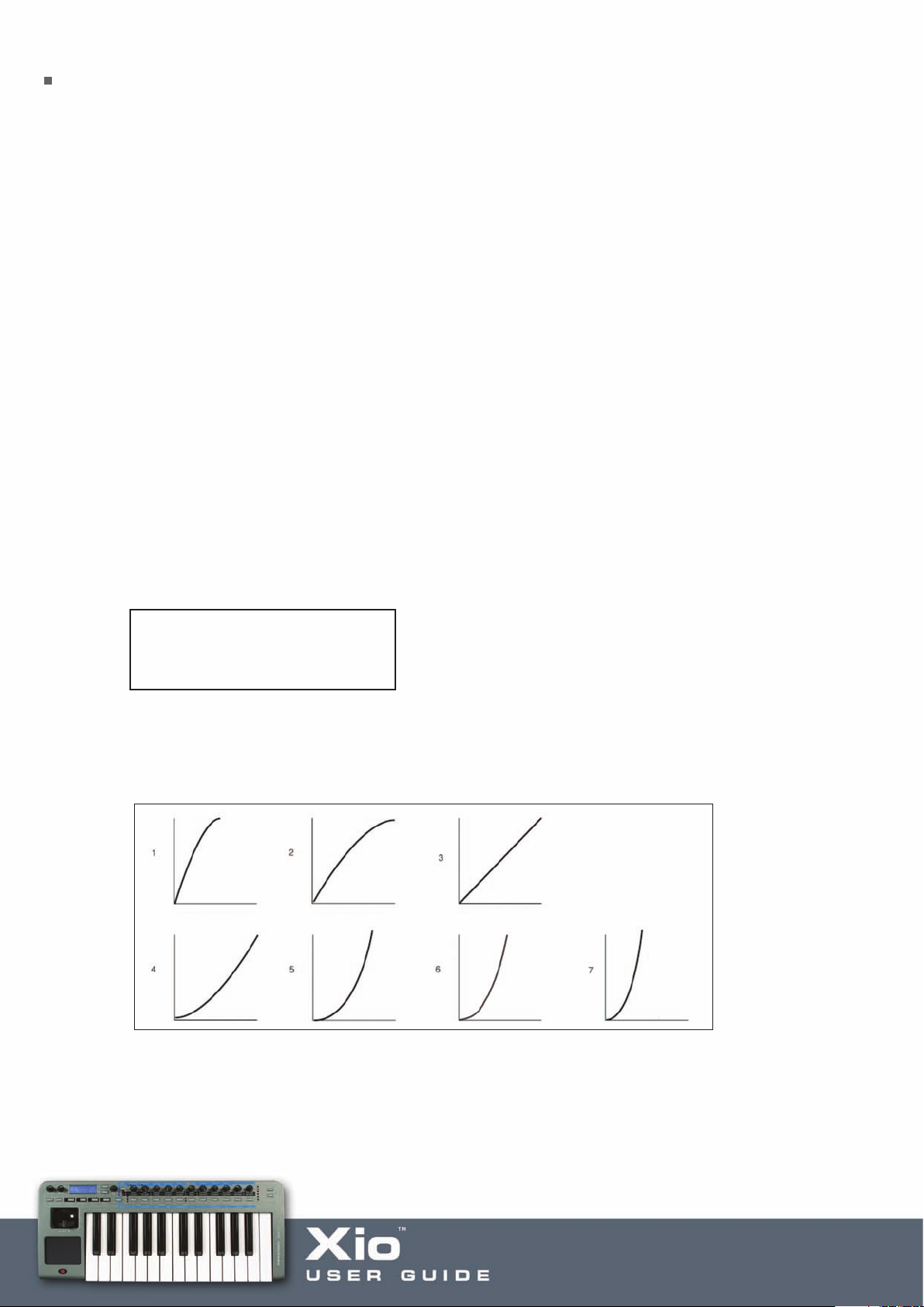
Edit Menu Page 1 – Velocity Curve Select
Velocity Curve:
XXX
This page allows a velocity curve for the Xio keyboard to be selected; this is the ratio of velocity of
transmitted data (relating to volume of sound) to the force with which the keys are pressed. Rotating the
A encoder selects between Curves 1-7. The velocity curves available are as follows:
T
DA
Curve selection No. 3 is the default setting. If a softer touch is required (lighter key presses giving the same
velocity output) then try selecting Curve 1 or 2. Alternatively, Curves 4, 5 and 6 provide a harder response.
Selecting a value of between 8 and 127 sets a fixed velocity value (of that amount) for the keyboard.
Page 49

Edit Menu Page 2 – Template Transpose
Template Trans:
XXX
This page allows the keyboard to be transposed within the Template. Rotating the DATA encoder will select
a value of XXX between - 64 and + 63. This will be the amount in whole semitones that the keyboard is
transposed by, e.g. to transpose up 4 semitones, set to + 4.
Edit Menu Page 3 – Keyboard Channel Select
Keyb MIDI Chan:
XX
This page defines the MIDI channel that the keyboard will transmit MIDI data on. Rotating the DATA encoder
will select a value of XX between 1 and 16. NB The MIDI channel for the pitch/mod joystick is separate from
this and programmable from within the individual Template (its MIDI channel can also be overridden using Edit
Menu Page 4 – Override Channel).
Edit Menu Page 4 – Keyboard Channel Select
Keyb MIDI Ports:
XXX
This page defines the MIDI ports that the keyboard will send MIDI data to. Rotating the DATA encoder will
select an option for XXX between OFF, USB, MIDI and USB+MIDI. NB The MIDI ports for the pitch/mod
joystick are separate from this and programmable from within the individual Template.
Edit Menu Page 5 – Override Channel
Override MIDI Ch:
XX
This page allows the user to quickly set all controls (knobs and buttons within the current template) to
send data on the same MIDI channel without having to individually edit each control. XX can be set as ‘OFF’
or at a value between 1 and 16 as required, using the DATA encoder. If MIDI channel 4 is selected then
all controls will output data on MIDI channel 4 despite how they have been individually assigned.
Page 50

Edit Menu Page 6 – X/Y Touchpad X Control Define
Touchpad X Type:
XXX
This page selects the type of X/Y Touchpad X-axis (horizontal) action. Rotating the DATA encoder scrolls
between three modes for XXX: No Spring, Spring Left and Spring Center.
1. No Spring – As soon as a finger is released from the touchpad, the value of the touchpad will remain in
the last touched position. A subsequent touch to the pad will result in a shift (at a sensible rate) to the new
touch value.
2. Spring Left – As soon as a finger is released from the Touchpad, the value of the Touchpad will shift back
to the far left (to a value of zero if 0-127 has been defined for this axis, or to a value of -64 if -64-+63 is
assigned to it).
3. Spring Centre – As soon as a finger is released from the Touchpad, the value of the Touchpad will shift
to the centre point of that axis (to a value of 64 if 0-127 is defined for that axis, or to a value of 0 if -64+63 is assigned to it).
Edit Menu Page 7 – X/Y Touchpad Y Control Define
Touchpad Y Type:
XXX
This page selects the type of X/Y Touchpad Y-axis (vertical) operation. Rotating the DATA encoder scrolls
between three modes for XXX: No Spring, Spring Down and Spring Center. See above for definitions (middle
option jumps down).
Edit Menu Page 8 – Hybrid Mode 1 Activation
Synth By Control:
XXX
This page activates Hybrid Mode 1, where the Xio keyboard and/or 2-D controls can be used to play the
onboard Synth whilst using the rest of the knobs and buttons to MIDI control. Use the data encoder to select
from the following options:
OFF – The Synth will be inactive
KBD – The keyboard will play the Synth (and the data encoder will select the sound being played)
Page 51

KBD+JOY – The keyboard and Joystick will play the Synth (and the data encoder will select the sound
being played)
KBD+PAD – The keyboard and Touchpad will play the Synth (and the data encoder will select the sound
being played)
KBD+PAD+JOY – The keyboard, Touchpad and Joystick will all play the Synth (and the data encoder will
select the sound being played)
Edit Menu Page 9 – Hybrid Mode 2 Activation
Synth By MIDI:
XXX
This page activates Hybrid Mode 2, where the Xio onboard Synth can be played by incoming MIDI data
received over USB. This means that all of the Xio controls (knobs, buttons, pad, stick) and keyboard could be
MIDI controlling various software or hardware, whilst the synth is being simultaneously played by a track
within the sequencer. Use the data encoder to set this to On or Off. When set to On, the data encoder is
used to select the Xio onboard sound being played by incoming MIDI data, when playing the Template.
Global Hybrid
OFF
This parameter helps select the synth patch that is used by the current template when either of the hybrid
modes ar
When set to On, the currently selected synth patch will be used as the global hybrid synth patch. This is the
same patch used across all templates that use hybrid mode and have global hybrid turned on.
If this is turned off, the template can reference a unique synth patch stored with the template. This is the
current synth patch when the template is written to memory.
e active. Use the data encoder to set this to On or Off.
Page 52

Using the X/Y Touchpad
The touchpad allows transmission of up to four MIDI data values, two on the X-axis (horizontal) and two
on the Y-axis (vertical). The MIDI data transmitted depends on how a finger moves along the Touchpad; by
moving a finger in a diagonal direction, both X- & Y-axis data is generated simultaneously. Alternatively, just
moving a finger along the bottom of the Touchpad will only transmit X-axis data.
Using the Touchpad in PLAY Mode
In PLAY mode, the display will show the values being sent out to the USB port and/or MIDI, for example:
X1 = 105 Y1 = 056
X2 = 087 Y2 = Off
If any of the X or Y controls have been set to ‘No Control’, then the display will show ‘Off’ for that control.
In the example above, the Y2 control has been set to ‘No control’, so only one parameter is assigned to the
Y-axis but two to the X-axis. This display allows the exact size of each parameter on each axis to be viewed
while in use, it does not allow the viewing of the type of MIDI data assigned to each axis. Edit Mode must be
selected to view the details of the MIDI data being transmitted by each axis (see below).
Using the Touchpad in EDIT Mode
By pressing the EDIT button once and entering the individual Template Edit Mode (the LED to the left of the
button will illuminate not flash), the MIDI data assigned to the Touchpad can easily be viewed and edited, as
with any of the Xio’
other control as there are essentially four different controls on the one Touchpad. With other assignable
controls (knobs and buttons), simply moving the control will suffice but these only have one parameter
assigned to them at any one time. W
any of the four parameters for edit. This is done by dividing the Touchpad into four quadrants, as follows:
s contr
ols. Selecting either X1, X2, Y1 or Y2 for edit is slightly different than editing any
ith the Touchpad in EDIT Mode, there needs to be a way of calling up
Page 53
Simply pressing and holding the Touchpad in one of the quadrants as shown in the diagram will first display
all MIDI data assigned to that control within the touchpad, as follows:
Filter Freq
55 CC74 1 U
If the X1 quadrant had been pressed, this would signify that Filter Frequency had been assigned to the first
parameter on the X-axis (horizontal) on Continuous Controller number 74, at a current value of 55. The 1
and U signify that X1 is transmitting on MIDI channel 1 and over USB.
Then the display will move to the first page of the Template Individual Edit Menu as it would do if any
assignable control was touched in this mode, showing the following:
Control Type:
55 CC
Now, whatever control within the Touchpad was pressed (X1, X2, Y1 or Y2) can be edited the same way
as any assignable control on the Xio. See the Template Individual Edit mode menus for more information on
how to do this.
Page 54

Using a Sustain Footswitch
A Sustain Footswitch socket on the rear panel can be used to plug in a pedal to sustain notes, in a similar
manner to the sustain pedal on a piano. This pedal is set to CC number 64 in the Factory preset Templates
but can be changed in the same way as any other assignable control (by pressing the pedal whilst in EDIT
mode and then stepping through the pages of available parameters).
In PLAY mode, the display will show the following when the footswitch is activated (providing no edits have
been made to its function):
Sustain Pedal
127 CC64 1 U
The value on the far left shows 127 to signify that the footswitch has been activated and is now ‘On’.
There are two settings, ‘On’ (127 is transmitted) and ‘Off’ (0 is transmitted).
In EDIT mode, the data assigned to the footswitch can be changed as with any assignable control. Simply
press the EDIT button once to enter individual Template Edit mode (the LED to the left of the button will
illuminate continuously, not flash) then press down on the footswitch to call up the first page of the Edit
menu for that control.
Page 55

Using the Octave Up/Down buttons
These buttons are DUAL function. They function in the normal manner in PLAY mode, shifting the Xio
keyboard up and down in octaves across the whole MIDI Note range. For example, if the OCTAVE UP button
is pressed once then the screen will show:
Keyboard Octave
55 C+1
When naming synth patches or Templates, however, the Octave buttons are used to move the cursor left
and right.
Page 56

Saving/Naming a Template
Once some edits have been made to an existing Template or an entirely new one has been constructed,
the Template must be saved to the onboard memory in order to recall that Template at a later date. The
other alternative is to send the Template to the Template Editor application that can be downloaded from
www.novationmusic.com and then save it to the desktop. If saving onboard though, simply pressing the
WRITE button will move through the saving procedure. After pressing once, the screen shows:
V-Station
To Template XX
V-Station is the name of the currently selected Template and XX is the number (from 1-16) of that Template.
Simply rotate the DATA encoder to select a different Template number if required, then press WRITE again
to save the current settings to that Template number.
If after the first press of the WRITE button, the screen shows:
MEMORY
PROTECTED
(The message will appear temporarily and then the Xio will return to PLAY mode.)
Then the Xio GLOBAL setting has activated Memory Protect, which will mean onboard Templates cannot be
overwritten. (See the GLOBAL memory section for details.)
Providing Memory Protect (in the GLOBAL menu) is off then, once the WRITE button has been pressed
for a second time, the LCD display will show:
Template ReName?
Fred Station
The name of the Template can now be modified if required by using the DATA encoder to change the
character fr
presses of the Menus/Audio button cycles between capitals, lower case, numbers or punctuation.
om A-Z, a-z, 0-9 etc. and the OCTAVE UP/DOWN arrows to move the cursor. Repeated
Page 57

Pressing the WRITE button a third time will show the following (final) screen temporarily, before returning to
EDIT mode:
TEMPLATE SAVED
It is possible to abort the WRITE procedure at any stage by pressing another Mode/Menu button (e.g. PLAY,
EDIT, GLOBAL).
If a Template is not saved to the Xio memory or sent to the Template Editor before selecting another
Template in PLAY mode or turning off the Xio, then the settings will be lost forever. However, there
are only 16 onboard Templates and overwriting one will replace it forever. So, it is advisable to install the
Template Editor so that Templates can easily be sent back and forth between the Xio and the computer. The
Template Editor has a ‘Restore Factory Templates’ button embedded within its ‘Bulk Dumps’ menu so
overwriting factory Templates is not a problem. Additionally, the editor allows the upload of the numerous
extra factory Templates available for the Xio from www.novationmusic.com.
Page 58

Playing the Synthesizer in MIDI Controlling Mode – Hybrid Mode
A great feature of the Xio is its ability to allow the Synth to be played whilst in MIDI Controlling mode,
meaning the full extent of the keyboard can be utilised. These Hybrid mode settings are accessed in the
Template Common Edit Menu, activated by pressing the EDIT button twice. The first page, Synth By Control,
allows the keyboard, joystick and touchpad to be assigned to control the onboard Synth. For example, if
wanting to use the keyboard and joystick to play the Synth, whilst using the Xio knobs, buttons and touchpad
to MIDI control software or connected hardware, set this to KYB+JOY. All the while in this mode, the
encoder is used to change the keyboard’s Synth Patch.
If wanting the Synth to be played by MIDI data from the Sequencer then scroll to the following Template
Common page, Synth By Midi, and set it to On. This means that, whilst using the MIDI Template to control
software or hardware, the keyboard’s Synth can be played by a MIDI track within the sequencer, as long as
that track is set to channel 16, or the corresponding channel set in the Synth Global Menu. (See the Synth
Global Menu section for details.)
Page 59
Guide to the onboard Templates
Ableton 5
ayout
L
Group A
Knobs 1-8: Track 1-8 Volume
Knobs 9 and 10: Free Assign 1 and 2
Knob 11: Cue Level
Buttons 1-8: Track 1-8 Solo
Buttons 9 and 10: Scene Up and Down
Button 11: Cycle
Group B
Knobs 1-8: Track 1-8 Sends
Knobs 9 and 10: Return A and B
Knob 11: Master Vol
Buttons 1-8: Track 1-8 Active
Buttons 9-11: Play, Stop and Record
Touchpad is assigned the Crossfader throughout.
Setup
No setup is required for the Template to work, but a Template session must be used. This session should be
opened before you start working on your track, as the relevant areas of the session have been assigned to
work with the Xio. The session has been created in Live 5 but will also work in Live 4.
Absynth 3
Layout
oup A
Gr
Knob 2: Volume, knobs 3-6: Filter Frequency, Resonance, Attack and Release Knobs 7-10: Amplitude Attack,
Decay, Sustain and Release
Knob 11: Ef
Buttons 1-11: No Control
Group B
Knobs 1-11: CC numbers for free assign
Buttons 1-11: No Control
fect level
Touchpad has modulation assigned to it throughout.
Setup
No setup is r
ed for the T
equir
emplate to work.
Page 60

Albino 2
Layout
Group A
Knobs 1 and 2: Osc 1 Cent and Volume
Knobs 3-5: Filter 1 Frequency, Resonance and Mod Depth
Knob 6: LFO 1 Rate
Knobs 7-10: Amp Attack, Decay, Sustain and Release
Knob 11: Master Volume
Buttons 1 and 2: Osc 1 On/Off and Type
Buttons 3 and 4: Filter 1 Mode and Type
Buttons 5 and 6: LFO 1 Waveform and Mono
Buttons 7 and 8: Amp Env Type and Loop
Button 9: No control
Buttons 10 and 11: Filter 1 On/Off, Filter 2 On/Off
Group B
Knobs 1 and 2: Osc 2 Cent and Volume
Knobs 3-5: Filter 2 Frequency, Resonance and Mod Depth
Knob 6: LFO 1 Delay
Knobs 7-10: Mod Attack, Decay, Sustain and Release
Knob 11: Arp Length
Buttons 1 and 2: Osc 2 On/Off and Type
Buttons 3 and 4: Filter 2 Mode and Type
Buttons 5 and 6: LFO 1 Waveform and Ret On/Off
Buttons 7 and 8: Mod Env Type and Loop
Button 9: No control
Buttons 10 and 11: Arp On/Off and Mode
Touchpad has Filter 1 Frequency and Resonance assigned to it throughout.
Setup
To allow control of Albino 2 using the Xio, load an instance of Albino 2 into your sequencer and select 'Load'
from the Easy Controller Setup (ECS) menu (click on the button labelled 'ECS' in the Albino 2 window). Then
locate and open the file 'XIO_ALBINO_2.MOD', found in the Albino Template folder on the Resources disk.
Page 61

Atmosphere/Trilogy
Layout
Group A
Knobs 1 and 2: Layer A Pitch Fine Tuning and Level
Knobs 3-5: Master Filter Cut, Resonance and Mod Env Depth
Knob 6: LFO Rate
Knobs 7-10: Amp Attack, Decay, Sustain and Release
Knob 11: Master Volume
Buttons 1 and 2: Layer Select and Layer A On/Off
Buttons 3-10: No Control
Button 11: Link On/Off
Group B
Knobs 1 and 2: Layer B Pitch Fine Tuning and Level
Knobs 3-5: Filter Cutof
Knob 6: LFO Depth
Knobs 7-10: Filter Envelope Attack, Decay, Sustain and Release
Knob 11: Glide Time
f, Resonance and LFO Mod Amount
Buttons 1 and 2: Layer Select and Layer B On/Off
Buttons 3-10: No Control
Button 11: Solo On/Off
Touchpad has M Filter Frequency and Resonance assigned to it throughout.
Setup
No setup is required for the Template to work.
B4
Layout
Group A
Knobs 1-9: Upper 16, 5 1/3, 8, 4, 2 2/3, 2, 1 3/5, 1 1/3, 1
Knobs 10 and 11: No Control
Button 1: Upper Vib On/Off
Buttons 2-7: No Control
Buttons 8-11: Perc, Drive, Rotator, Velocity On/Off
Group B
Knobs 1-9: Lower 16, 5 1/3, 8, 4, 2 2/3, 2, 1 3/5, 1 1/3, 1
Knobs 10 and 11: No Control
Page 62

B4 (continued)
Button 1: Lower Vib On/Off
Buttons 2-7: No Control
Buttons 8-11: Perc, Drive, Rotator, Velocity On/Off
Touchpad has Rotator Speed (x-axis) and Swell (y-axis) assigned to it throughout.
Setup
No setup is required for the Template to work.
Bass station
Layout
Group A
Knobs 1 and 2: Osc 2 Detune and Osc 1-2 Mix
Knobs 3-5: Filter Fr
Knob 6: LFO Speed
Knobs 7-10: Amp Attack, Decay, Sustain and Release
Knob 11: Amp Env Velocity
equency, Resonance and Mod Depth
Buttons 1 and 2: Osc 1 Sync and Waveform
Button 3: Filter Slope
Button 4: No Control
Button 5: LFO Waveform
Buttons 6-10: No Control
Button 11: Osc Voice Mode
Group B
Knobs 1 and 2: Osc 2 Semitones and Osc 1-2 Mix
Knobs 3-5: Filter Fr
Knob 6: LFO Delay
Knobs 7-10: Mod Env Attack, Decay, Sustain and Release
Knob 11: Mod Env Velocity
Buttons 1 and 2: Osc 2 Octave and Waveform
Button 3: Filter 2 Slope
Button 4: No Control
Button 5: LFO Waveform
Buttons 6-10: No Control
Button 11: Osc Voice Mode
equency, Resonance and LFO Amount
Touchpad has Aftertouch (x-axis) and Breath Control (y-axis) assigned to it throughout.
Setup
No setup is required for the Template to work.
Page 63

Cubase SX3
Layout
Group A
Knobs 1-8: Audio Track 1-8 Volume
Knobs 9 and 10: FX1 and 2 Level
Knob 11: Output Level
Buttons 1 and 2: Punch In and Out
Buttons 3 and 4: Cycle Record Mode and On/Off
Buttons 5-11: Transport
Group B
Knobs 1 and 2: Level and Pan
Knobs 3-5: Sends 1-3
Knobs 6-8: EQ 1 Gain, Frequency and Q
Knobs 9-11: EQ 4 Gain, Fr
Buttons 1 and 2: Track Mute and Solo
Buttons 3-5: Sends 1-3 On/Off
Buttons 6-9: EQ 1-4 On/Off
Buttons 10 and 11: Track Select Up/Down
equency and Q
Touchpad is assigned Aftertouch (x-axis) throughout.
Setup
To import the setup file, do the following:
1. Open Cubase application and go to Devices\Device Setup
2. Click on 'Add/Remove' tab (the + button in later versions) and add a 'Generic Remote'.
3. 'Generic Remote' will appear in the list on the left-hand side of the devices window
up the generic remote settings.
4. Click 'Import' and locate the set up file ‘Xio_SX.xml' on the resources disc (or 'Xio _SX2.xml' or 'Xio
_SX3.xml' depending on the version of Cubase).
5. Click 'Open' to load the setup file and select Xio as the MIDI input device at the top of the device setup
window (do NOT select it as the MIDI output).
6. Click 'Apply' and 'OK' to exit the device setup window.
All controls have been set to transmit on MIDI channel 16 so, when using the generic remote with the Xio in
Cubase, it is advisable to exclusively reserve MIDI channel 16 solely control Cubase. To do this open the
preferences dialog and select the MIDI Filter Page. Click on the '16' box in the Channel section to filter out
messages on channel 16, then click 'Apply' to save the changes followed by 'OK' to exit preferences.
. Click on this to bring
Page 64

Cubase SX3 (continued)
In order that the controls on the Xio work correctly with Cubase you need to use the appropriate default
Cubase arrangement supplied on the resources disc. Open the file 'Default_SX.cpr' (or 'Default_SX2.cpr' or
'Default_SX3.cpr' depending on the version of Cubase) to start making music with Cubase and theXioSynth. It
is recommended to copy the default Xio project into the Cubase templates folder so that it is available in the
templates box when you open a new session.
The Cubase templates folder is found in the following location:
PC - Program Files\Steinberg\Cubase\Templates
Mac - Applications\Cubase\Contents\Templates (Control click on the Cubase application and select 'Show
Package Contents' to get to the 'Contents' folder)
FM7
Layout
Group A
Knob 1: Freq Ratio Low
Knob 2: Level
Knobs 3-5: Timbre Bright, Harmonic and Env Amount
Knob 6: LFO Rate
Knobs 7-10: Amp Attack, Decay, Sustain and Release
Knob 11: Effect Strength
Buttons 1 and 2: Operator and Wave
Buttons 3-10: Op Sel, A-F, X and Z On/Off
Button 11: Effect On/Off
oup B
Gr
Knobs 1 and 2: Freq Ratio Mid and LFO Vibrato
Knob 3: Timbre Velocity Sensitivity
Knob 4: Timbre Detune
Knob 5: LFO Timbre
Knob 6: No Control
Knob 7-10: Timbre Attack, Decay, Sustain and Release
Knob 11: Delay Feedback
Buttons 1 and 2: Operator and Wave
Buttons 3-10: O. S, B-F, X and Z On/Off
Button 11: D. T. Sync
Touchpad has Timbre Bright (x-axis) and Timbre Harmonics (y-axis) assigned to it throughout.
Page 65

FM7 (continued)
Setup
There is an FM7 setup file ‘Xio_LE.F7c’ on the Resources disk, which must be loaded into the FM7.
To load the file into the FM7, click on the controller ‘LOAD’ button in the master section of the FM7.
Navigate to the file ‘Xio_LE.f7c and open it. Note this can then be saved to the c:/program files/native
instruments/FM7/assigns folder where C: is the hard drive that the FM7 is installed on. From the FM7
preferences option, make sure that the following options are checked:
1 MIDI controller range 000-127
2 0...63: off 64...127: on
3 Use OP A controllers for selected op
4 OP Select controller: 9
5 Use 3 ccs for ratio.
Logic 7
Layout
Group A
Knobs 1 and 2: Track Level and Pan
Knobs 3-10: Track 1-8 Sends
Knob 11: Master Vol
Buttons 1 and 2: Track Up and Down
Buttons 3 and 4: Mute and Solo
Buttons 5 and 6: Record Enable and Hide View
Buttons 7-11: Transport (Record, Play, Stop, Rewind, Forward)
Group B
Knobs 1-10: Bus 1-10 Level
Knob 11: Out 1-2 Level
Buttons 1 and 2: Loop and Toggle Drop
Buttons 3 and 4: Mute and Solo
Buttons 5 and 6: Sync and Click On/Off
Buttons 7-11: Transport (Record, Play, Stop, Rewind, Forward)
Touchpad is assigned Aftertouch (x-axis) throughout.
Setup
Locate the files 'com.apple.logic.pro' and 'com.apple.logic.pro.cs' in the folder:
User/Library/Preferences/Logic
Page 66

Logic 7 (continued)
Then replace them with the ones in the Logic 7 folder on the Resources disk. Note that any existing Control
Surface and Key Command preferences will be overwritten. The project 'XIO_LOGIC_PRO_7.lso' has been
created to correspond best to the Xio assigned controls. To save this as the default Logic project rename it
'autoload.lso' and place it in the folder:
User/Library/Application Support/Logic/Song Templates
Note that it is not necessary to use 'XIO_LOGIC_PRO_7.lso' project when using the Xio to control Logic Pro
7.
Minimonsta
Layout
Group A
Knobs 1 and 2: Osc 1 Range and Mix
Knobs 3-5: Filter Cut, Emphasis and Centre
Knob 6: Mod Mix
Knobs 7-9: VCA Attack, Decay and Sustain
Knob 10: Master Volume
Knob 11: Delay Amount
Buttons 1 and 2: Osc 1 On/Off and Waveform
Buttons 3 and 4: VCF Keyboard 1 and 2
Buttons 5 and 6: Osc 3 Control and Osc Mod
Buttons 7-11: No Control
Group B
Knobs 1 and 2: Osc 2 Range and Mix
Knob 3: Osc 3 Mix
Knob 4: Noise Mix
Knob 5: Ext Input Mix
Knob 6: Mod Mix
Knobs 7-9: VCF Attack, Decay and Sustain
Knob 10: No Control
Knob 11: Delay Feedback
Buttons 1 and 2: Osc 2 On/Off and Waveform
Button 3: Osc 3 On/Off
Button 4: Noise On/Off
Button 5: Noise Colour
Button 6: Filter Mod
Buttons 7-11: No Control
Page 67

Minimonsta (continued)
Touchpad is assigned Filter Cut (x-axis) and Emphasis (y-axis) throughout.
Setup
No setup is required for the Template to work.
Oddity
Layout
Group A
Knob 1: V1 FNTNE
Knob 2: VCO 1 Level
Knobs 3-5: VCF Frequency, Resonance and Mod 3 Amount
Knob 6: LFO Frequency
Knobs 7-10: Amp Attack, Decay, Sustain and Release
Knob 11: VCA Mod Level
Button 1: No Control
Button 2: VCO 1 Tri/Square
Buttons 3 and 4: No Control
Button 5: VCF Mod 3 Source
Button 6: Tempo LFO Sync
Button 7: ADSR Gate Repeat
Button 8: ADSR Repeat Auto
Buttons 9 and 10: No Control
Button 11: VCA Mod Source
Group B
Knob 1: VCO2 Fine Tuning
Knob 2: VCO 2 Level
Knob 3: HPF Cutoff Frequency
Knobs 4 and 5: VCF Mod 1 and Mod 2 Amount
Knob 6: LFO Frequency
Knobs 7 and 8: AR Attack and Release
Knobs 9 and 10: Velocity to VCA and Velocity to VCF
Knob 11: Portamento
Buttons 1 and 2: VCO 2 Sync and Tri/Square
Button 3: No Control
Buttons 4 and 5: VCF Mod 1 and Mod 2 Source
Button 6: Keyboard LFO Retrig
Button 7: AR Gate Repeat
Buttons 8-10: No Control
Button 11: Mono/Duo Mode
Touchpad is assigned VCF Resonance (x-axis) and VCF Cutoff Frequency (y-axis) throughout.
Page 68

Oddity (continued)
Setup
No setup is required for the Template to work.
PRO53
Layout
Group A
Knobs 1 and 2: Osc A Frequency and Level
Knobs 3-5: Filter Frequency, Resonance and Envelope Amount
Knob 6: LFO Freq
Knobs 7-10: Amp Attack, Decay, Sustain and Release
Knob 11: Delay Wet
Buttons 1 and 2: Osc A Waveform Saw and Osc A Waveform Square
Button 3: No Control
Button 4: High-pass On/Off
Button 5: LFO Saw Waveform
Button 6: LFO Pulse Waveform
Button 7: Amp Env Hold
Buttons 8 and 9: No Control
Buttons 10 and 11: Delay Sync and On/Off
Group B
Knobs 1 and 2: Osc B Fine Tuning and Level
Knob 3: Filter Keyboard Track,
Knob 4: Analogue
Knob 5: Poly-Mod Osc B
Knob 6: LFO Noise
Knobs 7-10: Filter Attack, Decay, Sustain and Release
Knob 11: Glide
Buttons 1 and 2: Osc B W
Button 3: No Control
Button 4: High-pass On/Off
Button 5: LFO Tri Waveform
Button 6: LFO Pulse Wave
Button 7: Freq Env Invert
Buttons 8-10: No Control
Button 11: Unison
Touchpad has Filter Frequency and Resonance assigned to it throughout.
aveform and Osc B Waveform
Setup
The Pro 53 uses a learn facility to remember controllers. The controller values assigned to the Pro-53
template can either be learn't by the Pro 53 or a preference file 'XioSynthPro 53.txt' can be imported from
the Resour
ces disk into the Pr
o-53.
Page 69

Reason
Although there is no Template onboard the Xio for Reason 3, there are Resource files to enable the
keyboard to work as a controller for each instrument and rack device in the software. Once the Resource
files have been placed in the correct location, the keyboard can be set up as a Control Surface in Reason,
during which process a Template will be sent to the Xio.
Setup
The file 'Xio.midicodec' should be placed in the following folder:
PC (Win XP): C:\Documents and Settings\All Users\Application Data\Propellerhead
Software\Remote\Codecs\MIDI Codecs
Mac (OS X): HD/Library/Application Support/Propellerhead Software/Remote/Codecs/MIDI Codecs
The file 'Xio.remotemap' should be placed in the following folder:
PC (Win XP): C:\Documents and Settings\All Users\Application Data\Propellerhead
Software\Remote\Maps/Novation
Mac (OS X): HD/Library/Application Support/Propellerhead Software/Remote/Maps/Novation
Next, ensure that the Xio is connected and switched on, then open Reason 3. Open the Preferences dialog
and select the 'Control Surfaces and Keyboards' page. Select 'Add' to bring up the Control Surface dialog
and select Novation from the 'Manufacturer' drop down menu and 'Xio' from the 'Model' drop down menu.
Next select 'Xio' in the MIDI input drop down menu (do not select a MIDI output) and click 'OK'. A Reason 3
template will automatically be loaded into the Xio, which will then need to be saved
to the Xio's memory. The setup will then be complete and the Preferences dialog can be closed.
Sonar
Layout
Group A
Knobs 1-8: Tracks 1-8 Volume
Knobs 9-11: No Control
Buttons 1-8: Tracks 1-8 Mute
Buttons Knobs 9-11: Stop, Play and Record
Group B
Knobs 1-8: Tracks 1-8 Volume
Knobs 9-11: No Control
Buttons 1-8: Tracks 1-8 Mute
Buttons Knobs 9-11: Stop, Play and Record
Page 70

Sonar (continued)
Setup
The Sonar template uses the Generic Control Surface Feature found in Sonar to map incoming controller
messages to specific functions within Sonar. These are primarily Console and transport functions.
Start Sonar and open or create a project. Click on Options in the top tool bar and select Control Surface
from the drop down list. A connected control surface dialogue box will appear. There should be a Cakewalk
Generic Surface listed under Control Surface. If not, click the button to Add new Control Surface found within
this dialogue box. A new dialogue box will appear. Select Cakewalk Generic Surface from this list and click ok.
The new dialogue box will close.
Double click the Cakewalk Generic Surface from the Connected
Surfaces dialogue box. Select Xio or USB Audio device as the MIDI input and output.
Close the dialogue box.
Click on Tools in the top tool bar. Select Cakewalk Generic Surface from the drop down list. Name the Preset
‘Xio (T
ype in the empty ‘Presets’ box on the top left of window). Set the Number of Track Strips to 8 in the
corresponding box.
In track parameters set:
Parameter 1 to Volume, 2 to Pan, 3 to Solo and 4 to Mute
Then each individual control needs to be ‘Learned’. Highlight the parameter to be learned then hit Learn
button, then move the corresponding knob or button on the Xio (using the layout guide above) to learn the
control. Note ‘Configure Strip Number’ box 1-8, which corresponds to track 1-8, e.g. set this value to 5 to
learn the controls for track 5 by clicking each parameter, then the learn box, then moving each control in
turn. Repeat for all controls (including transport) then save the preset. This will then be saved for all future
projects.
Vanguard
Layout
Group A
Knobs 1 and 2: Osc 1 Semi and Vol
Knobs 3 and 4: Filter Cut and Resonance
Knob 5: Envelope 2 Cut
Knob 6: LFO1 Speed
Knobs 7-10: Envelope 1 Attack, Decay, Sustain and Release
Knob 11: Delay Mix
Button 1: No Control
Button 2: Osc 1 Waveform
Buttons 3-11: No Control
Page 71

Vanguard (continued)
Group B
Knobs 1 and 2: Osc 2 Semi and Vol
Knob 3: Fatness
Knob 4: Drive
Knobs 5 and 6: LFO 2 Cut and Speed
Knobs 7-10: Envelope 2 Attack, Decay, Sustain and Release
Knob 11: Reverb Mix
Button 1: No Control
Button 2: Osc 2 Waveform
Buttons 3-11: No Control
Touchpad has Filter Frequency and Resonance assigned to it throughout.
Setup
No setup is required for this Template to work.
V-Station
Layout
Group A
Knobs 1 and 2: Osc 1 Detune and Osc 1 Level
Knobs 3-5: Filter Frequency, Resonance and Mod Depth
Knob 6: LFO Speed
Knobs 7-10: Amp Attack, Decay, Sustain and Release
Knob 11: Arp Tempo
Buttons 1 and 2: Osc 1 Octave and Waveform
Button 3: Filter Slope
Button 4: No Control
Buttons 5 and 6: LFO 1 Waveform and K Sync
Butons 7 and 8: Amp Envelope Trigger and Amp Trig Multi
Button 9: No Control
Buttons 10 and 11: Arp Latch and Arp On/Off
Group B
Knobs 1 and 2: Osc 2 Detune and Level
Knobs 3-5: Filter Tracking, Overdrive and LFO Amount
Knob 6: LFO 2 Speed
Knobs 7-10: Mod Env Attack, Decay, Sustain and Release
Knob 11: A G Time
Page 72

V-Station (continued)
Buttons 1 and 2: Osc 2 Octave and Waveform
Button 3: Filter 2 Slope
Button 4: No Control
Buttons 5 and 6: LFO 2 Waveform and Key Sync
Buttons 7 and 8: M T Sing and MLT
Button 9: No Control
Buttons 10 and 11: Arp Key Sync and Octave
Touchpad has Filter Frequency and Resonance assigned to it throughout.
Setup
No setup is required for the Template to work.
User
The User T
Template for software with a MIDI learn facility.
emplate has different CC numbers assigned to each control so is ideal for creating your own
Page 73

Audio Recording and playback
hilst in either Synth or MIDI controlling mode, the Xio can be used to output or input audio to your
W
omputer. Similarly, if using the keyboard in standalone mode (powering off batteries or an external power
c
upply), then a microphone and line level signal can be amplified and mixed and sent to the line Outputs for
s
recording; this way, the Xio acts as a miniature Mixing desk.
Audio Playback
To send audio from a sequencer to speakers, simply connect active (powered) speakers or an amplifier
directly to the Xio Line Outputs and use the level control (Line Out Vol) on the far left of the front panel to set
the level. Providing the Xio is now connected over USB and set up as an audio interface in the sequencer
preferences, audio from your session can be played using the connected speakers.
Audio Recording
To record audio to your sequencer, a microphone (Input 1), line-level or instrument (e.g. guitar) signal (Input
2) needs to be connected to the rear panel.
Microphone Recording
If plugging a microphone into Input 1 (XLR Input), the phantom power setting in the Global Menu may need
activating before a signal is heard. This normally only applies to condenser microphones and should be used
carefully as ribbon mics can be damaged by phantom power. Check your microphone’s User Guide for more
information. To turn on phantom power, press the GLOBAL button and scroll to the following page:
Phantom Power:
XXX
(If in Synth mode, make sure that the normal Global mode is active and not the Synth Global mode –
these two modes are activated by alternate presses of the GLOBAL mode button.)
Use the data encoder to select 48V. If using a mic that accepts less power and trying to conserve energy
(if running off batteries for example), then 12 or 24V can be selected as required.
Now, the row of knobs on the Xio must be put into Audio mode, so that the Input levels can be accessed. To
do this in MIDI controlling mode, simply press the Menus/Audio button so that the top LED lights (indicating
that the blue strip of AUDIO parameters running across the top of the front panel is now active). If in Synth
mode, the Menus/Audio button must be pressed and held to light the top LED; pressing and releasing, so
that the bottom LED lights, activates the Synth Menus mode.
Page 74
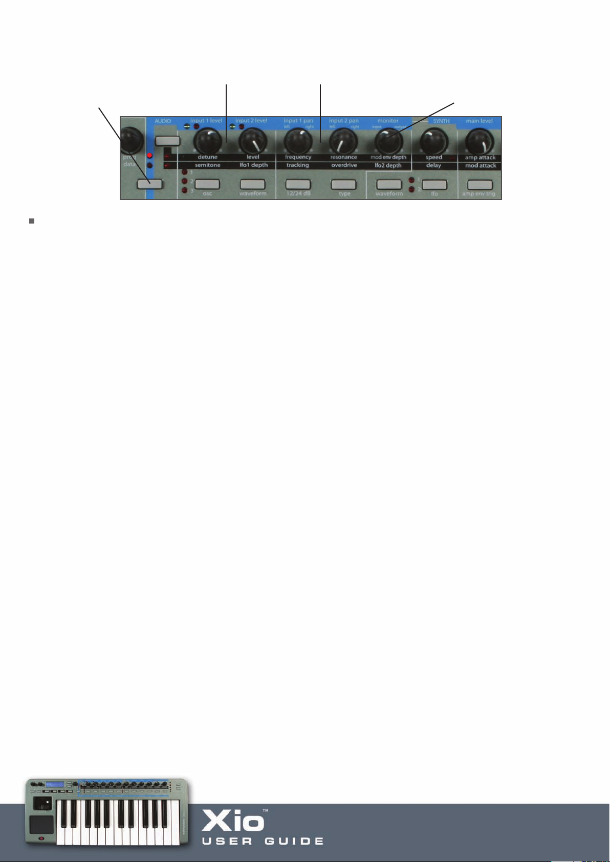
Once the top Audio LED is active, the knobs can be used to adjust the Input levels accordingly, as follows:
upper LED will light). Press
(
nd hold if in Synth mode
a
udio Inputs 1 and 2 Level Audio Inputs 1 and 2 PanningPress to activate Audio mode
A
lend between Levels of
B
nputs and Playback tracks
I
Latency-free monitoring)
(
Line-Level/Instrument Recording
To record a line-level signal (Input 2), connect a 1/4” Jack into the rear panel socket and set the level of the
Input using the corresponding knob on the front panel (in AUDIO mode as detailed above). If wanting to
record an instrument like a guitar, then the signal can be plugged in directly to Input 2 and recorded by
exactly the same means.
Page 75

GLOBAL Menu
lobal Edit menu page 1 – Memory Protect
G
Memory Protect: XXX
This page of the menu allows protection of the Xio onboard memory to be activated. Using the
Data encoder to select XXX as ‘On’ will mean that none of the 12 onboard Templates can be overwritten.
Choosing ‘Off’ will mean that the WRITE button procedure for saving onboard Templates or Synth patches
can be carried out.
Global Menu Page 2 – Phantom Power
Phantom Power:
XXX
Use the data encoder to select OFF, 12, 24 or 48V to supply the relevant phantom power to a microphone
connected to Input 1 (XLR Input).
Global Menu Page 3 –Dump Template(s)/Synth patches
Dump:
Current Template
This page allows an individual onboard Template, set of all 16 Templates, the Global settings, an individual
Synth patch or an entir
Editor. Rotating the Data encoder selects between the following options:
rent Template, All Templates, Send Globals, Current Sound, Sound Bank 1 or Sound Bank 2 (The last
Cur
three options will only appear when in Synth mode.)
Pressing the WRITE button once will then send the currently selected Template to the receiving device
as a sysex message. To indicate completion, the screen will flash:
e Sound Bank to be dumped (sent) to a destination, most likely the Xio Template
DONE
Page 76

Global Menu Page 4 – MIDI data routing
USB to MIDI Out:
XXX
This page allows the MIDI data received at the USB port to be routed directly to the MIDI Out port,
for controlling external hardware with the Xio. Set this to On or Off, as required.
Global Menu Page 5 – Global pot action
Pot/Slid Ovride:
XXX
This page allows a Global knob action (Jump or Pickup) to be set, which will override any individual control
settings (set in EDIT mode). Set this to PICKUP or JUMP for the override to take effect. Set to OFF for the
individual control settings to take effect.
Global Menu Page 6 –Set Display timeout
Display Timeout:
XXX
This page sets the amount of time that the LCD display shows temporar
when an assignable control is moved. Rotating the DATA encoder sets XXX at a value between 0 and
1260 ms, and then PERMANENT.
Global Menu Page 7 – Sustain Pedal Settings
y screens such as the MIDI data
Sustain Pedal
XXX
This page allows one of several Sustain Pedal actions to be activated:
AUTO automatic pedal action (this is the default setting)
NormOPEN close when pressed
NormCLSD open when pressed
Page 77

Global Menu Page 8 – Retain Template values
Retain Template
values: XXX
This page allows edited Template values to be remembered without the WRITE process having been done
(whilst the Xio is powered). This means that, during a session, a Template can be used to edit a plug-in and
then, if another Template is selected and edited, returning to the first Template will mean that the last edited
values are remembered. Set to ON for this function to be active. Powering down the Xio will mean that these
edited values are lost. Set to OFF for the saved Template values to always become active when a Template is
selected, regardless of the last edits made.
Global Menu Page 9 – Calibrate Pitch / Mod Wheel
Cal Pitch/Mod
--- ---
This page allows the pitch/mod joystick to be calibrated (set to the necessary data values for correct
operation). To calibrate, simply move the joystick from extreme left to extreme right. The display should
show a range of 0-255 under the word pitch. Then move the joystick from extreme top to extreme bottom.
The display should show a range of 0-127 under the word mod.
Global Menu Page 10 – Operating System Update
New O/S from USB
Press Write...
This page allows the Operating System (OS) of the Xio to be updated. This should be carried out if a new OS
has become available on the Novation website for download. In order for the Xio to receive the new OS (a
.syx file from the computer), the keyboard must be in ‘Listen’ mode. This is done by navigating to this screen
and pressing the WRITE button. The Xio will then be awaiting the delivery of a new OS over USB.
Note that in Synth Mode, there are two Global Menus. The first is the Main Global Menu, detailed above,
and the second is the Synth Global Menu. These two Menus are accessed by alternate presses of the
GLOBAL button.
Page 78

Using the WRITE button in Global edit mode
The WRITE button saves any changes that have been made to the GLOBAL settings. Once pressed,
the screen will briefly display the following message before returning to PLAY mode:
GLOBALS SAVED
Page 79

PREVIEW MODE
hen the Xio is in Preview Mode you can operate any pot, any button, the XY touchpad or a sustain pedal
W
o see its current value on the Xio display without actually changing the control value. This applies to when the
t
io is in synth mode or MIDI controller mode and also to when you are editing the audio interface settings.
X
To put the Xio into Preview Mode press and hold both the effects up/down selector buttons for one second.
All of the effects LEDs will light to indicate that Preview Mode is active. If the Xio is in synth mode the LED
for the currently effect will remain unlit but all others will light. To exit Preview Mode press hold both the
effects up/down selector buttons once more.
Page 80

Updating the Operating System
he last page of the GLOBAL Edit menu allows a new Operating System to be received by the Xio.
T
o access this page, press the GLOBAL button so that the LED to the left of it illuminates, then scroll using
T
he Page Up button to page 9 so that the screen shows:
t
New O/S from USB
Press Write...
Now press the WRITE button to put the Xio in ‘waiting’ mode. The Xio will then be waiting for
an OS to be sent using the updating software provided with the download.
Page 81

Troubleshooting
io is not powering up
X
Is the keyboard connected over USB or attached to an external power supply, or have batteries
•
een inserted?
b
• Is the power select switch on the rear panel in the correct position? It must be in the extreme left or
right position for the keyboard to be powered.
Xio is not appearing as a MIDI controller/Audio Interface in the sequencer
• Is the connected computer running on Win XP or Mac OSX? These are the only supported
Operating Systems.
• Is the keyboard connected over USB? With some sequencers, the keyboard will need to have been
connected before the sequencer is booted up.
An onboard Template isn’t working properly
• Is the receiving device (connected hardware or plug-in on a MIDI track within the sequencer) set up to
receive MIDI information from the Xio on the correct MIDI channel?
• Has the relevant setup procedure been carried out? All sequencer Templates and some plug-ins require
a setup to be carried out before they will work. (See the Templates Guide section for details.)
• Is an override MIDI channel selected in the Template Common Edit Menu?
The onboard synthesizer isn’t working
• Is the Xio in the correct mode? Pressing the PLAY button alternates between Synth and MIDI
Controlling modes.
• Is the Synth level turned up? Press and hold the Menus/Audio button and then rotate knob 7 to adjust.
Xio onboard synthesizer audio is not appearing on an audio track within the sequencer
• Has the Xio been set up as an Input Audio device in the sequencer preferences?
• Is the Synth USB Level turned up?
Xio onboard synthesizer is not responding to MIDI information sent from the sequencer
• Does the sequencer track have Xio selected as the source for the MIDI Output?
Is the sequencer track sending on MIDI Channel 16? This is the default setting in the Synth Global Menu.
•
• If in Hybrid Mode, is the Synth By Midi page in the Template Common Menu (activated by pressing the
EDIT button twice) set to ON?
Audio from the sequencer is not being heard at the Line Outputs
• Has the Xio been set up as an Output Audio device in the sequencer preferences?
• Is the Monitor knob (that blends between Inputs and Outputs) in a sufficiently clockwise position? In the
extreme anticlockwise position, no Output tracks from the sequencer will be heard.
For more comprehensive technical support, visit the online Answerbase @ www.novationmusic.com
Page 82

Specifications
ynthesizer
S
ne part, 8-voice polyphonic
O
Oscillators, 17 Waveforms
3
2 LFOs, 32 Waveforms
Multimode resonant filter section with various filter options
Extensive modulation capabilities
Arpeggiator with latch
X-GATOR with latch
Direct streaming of synth into computer via USB
Keyboard
Type: Semi-weighted
Velocity curves: 7
Pitch and mod wheel mechanism
Pitch wheel lever: Rubberised - centre return spring
loaded left to right motion
Mod/control lever: Rubberised - spring loaded front
to back motion
X/Y touchpad
Touchpad: 1 x touch sensitive 45x60mm
Parameters: 2 assignable in X direction
2 assignable in Y direction
LCD display
LCD: 2 x 16 character silver
Blue LED backlit
MIDI interfacing
MIDI: 1 MIDI Out
USB MIDI: 1 In/1 Out
Other inter
Data ports: 1 x USB 1.1
Sustain pedal: 1 x 1/4” Jack Input
facing
Page 83

Controls
Rotary potentiometers: 11, 0-270° rotation
Rotary encoders: 1, 360° continuous DATA wheel
Buttons: 11 function switches
Group B switch
General operation: 4 Mode and Menu select buttons
Keyboard Octave Up and Down buttons
Synth Menus/Audio mode select button
Effect Select buttons (Synth Mode)
Template/Bank/Page Up/Down buttons
Line/Phones Volume pots
General
Battery operation: 6 x standard 'AA' Size
External power supply: Standard 'centre positive' 9V DC 600mA (Novation PSU6)
Size: 468 x 68 x 190 (mm) w x h x d
Weight: 1.4kg
System requirements
Operating system: Mac OSX 10.2.4 or greater or Windows XP
Computer spec: Apple G3/400 GHz or Pentium 600 MHz or better
Interfacing: USB 1.1 compatible USB connector
Templates (16 preset onboard, more available on Novation website)
1. Apple – Logic 7
2. Steinberg – Cubase SX3
3. Ableton – Live 5
4. Cakewalk – Sonar
5. Native Instr
6. Native Instruments - B4
7. Native Instruments - FM7
8. Native Instruments - Pro53
9. Gmedia - Oddity
10. Novation V-Station
11. Novation Bass Station
12. reFX – Vanguard
13. Linplug – Albino 2
14. Gmedia - Minimonsta
15. Spectrasonics - Atmosphere & Trilogy
16. User Template
uments - Absynth 3
 Loading...