

Page 1

FRONT PANEL.....................................................................................................................................................................2
BACK PANEL.......................................................................................................................................................................3
SETTING UP........................................................................................................................................................................4
PLAYING THE FACTORY DEMO........................................................................................................................................5
BASIC SETUP .................................................................................................................... ..................................................6
ADVANCED SETUP.............................................................................................................................................................7
ABOUT ANALOGUE SYNTHESIS .......................................................................................................................................8
ABOUT FM SYNTHESIS......................................................................................................................................................17
ABOUT EFFECTS................................................................................................................................................................20
NOVATIONISH - NOVATION JARGON................................................................................................................................24
ABOUT PROGRAMS...........................................................................................................................................................25
ABOUT DRUM MAPS..........................................................................................................................................................26
ABOUT PERFORMANCES..................................................................................................................................................27
ABOUT FAVOURITES..........................................................................................................................................................29
ASSIGNING FAVOURITES..................................................................................................................................................30
INSERTING A FAVOURITE INTO AN EXISTING FAVOURITES MAP...............................................................................31
DELETING A FAVOURITE FROM AN EXISTING FAVOURITES MAP ...............................................................................32
SELECTING PROGRAMS, PERFORMANCES & FAVOURITES........................................................................................33
SELECTING DRUM MAP AND DRUM MAP PROGRAMS.................................................................................................34
EDITING & WRITING ARPEGGIATOR PATTERNS............................................................................................................35
EDITING & WRITING PROGRAMS.....................................................................................................................................38
MASTER VOLUME SECTION.............................................................................................................................................46
MODE SECTION..................................................................................................................................................................47
DISPLAY SECTION..............................................................................................................................................................60
KEYPAD SECTION..............................................................................................................................................................61
ARPEGGIATOR SECTION...................................................................................................................................................63
OSCILLATOR SECTION......................................................................................................................................................72
FILTER SECTION.................................................................................................................................................................89
LFO SECTION......................................................................................................................................................................96
INPUTS SECTION................................................................................................................................................................100
USING FOOTSWITCHES....................................................................................................................................................103
USING PEDALS...................................................................................................................................................................106
PROBLEMS THAT CAN OCCUR WHEN USING FOOTSWITCHES & PEDALS...............................................................108
VOCODER SECTION...........................................................................................................................................................109
ENVELOPES SECTION.......................................................................................................................................................112
EFFECTS SECTION............................................................................................................................................................119
PART EDIT SECTION ..........................................................................................................................................................134
MULTITIMBRAL USE...........................................................................................................................................................142
USING A SEQUENCER........................................................................................................................................................144
MASTER KEYBOARD FUNCTIONS - PART EDIT SECTION.............................................................................................150
TROUBLESHOOTING..........................................................................................................................................................158
UPGRADING THE SOUNDS ..............................................................................................................................................161
UPGRADING THE OPERATING SYSTEM..........................................................................................................................162
PROBLEMS THAT CAN OCCUR WHEN UPDATING AN OS ............................................................................................163
SPECIFICATION..................................................................................................................................................................165
BANK MESSAGES...............................................................................................................................................................166
MIDI CONTROLLER TABLE................................................................................................................................................167
NRPN TABLES.....................................................................................................................................................................168
MIDI IMPLEMENTATION CHART........................................................................................................................................181
PROGRAM BANK A .............................................................................................................................................................182
PROGRAM BANK B .............................................................................................................................................................183
PROGRAM BANK C.............................................................................................................................................................184
PROGRAM BANK D.............................................................................................................................................................185
PROGRAM BANK E .............................................................................................................................................................186
PROGRAM BANK F.............................................................................................................................................................187
PROGRAM BANK G............................................................................................................................................................188
PROGRAM BANK H.............................................................................................................................................................189
DRUM MAP A.......................................................................................................................................................................190
DRUM MAP B.......................................................................................................................................................................191
DRUM MAP C......................................................................................................................................................................192
DRUM MAP D......................................................................................................................................................................193
DRUM MAP H ......................................................................................................................................................................194
PERFORMANCE BANK A...................................................................................................................................................195
PERFORMANCE BANK B...................................................................................................................................................196
MONOPHONIC PRESET PATTERNS.................................................................................................................................197
POLYPHONIC PRESET PATTERNS...................................................................................................................................198
DISTRIBUTORS...................................................................................................................................................................199
INDEX...................................................................................................................................................................................200
NOTES.................................................................................................................................................................................204
MENU MAP..........................................................................................................................................................................207
CONTENTS
1
Page 2
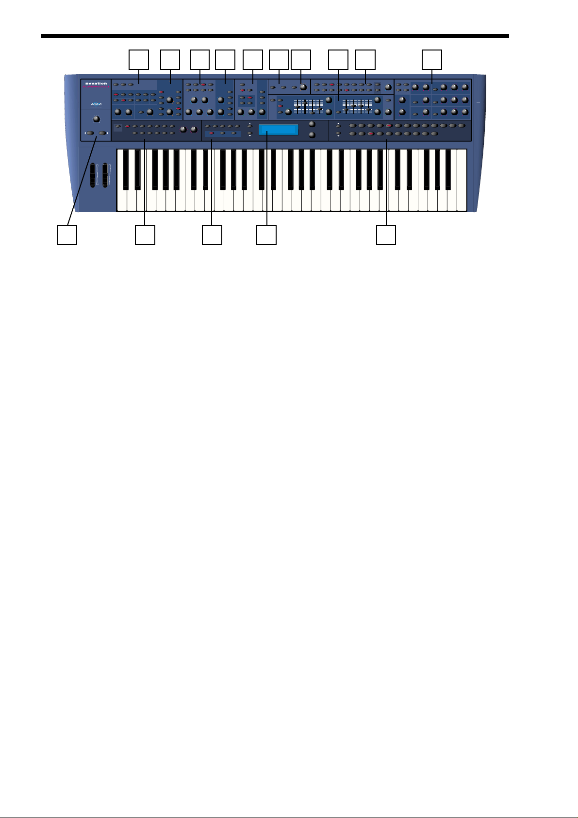
FRONT PANEL
1 - Master V olume Section
This section contains the Master Volume knob and the Octave Up & Down buttons.
2 - Oscillator Section
This section contains all the Knobs and buttons associated with the Oscillators.
3 - Arpeggiator Section
This section contains all the Knobs and buttons associated with the Arpeggiator.
4 - Oscillator Modulation Matrix Section
This section contains all the Knobs and buttons associated with the Oscillators Modulation Matrix.
5 - Filter Section
This section contains all the Knobs and buttons associated with the Filter.
6 - Mode Section
This section contains all the buttons used to select the various playing modes.
7 - Filter Modulation Matrix Section
This section contains all the Knobs and buttons associated with the Filter Modulation Matrix.
8 - LFO Section
This section contains all the Knobs and buttons associated with the 2 LFOs.
9 - Display Section
This section contains the Display, the Data Knobs and Page buttons.
10 - Input Section
This section contains all the buttons associated with the 2 Inputs.
11 - Vocoder Section
This section contains the Menu button and Balance knob associated with the Vocoder.
12 - Envelopes Section
This section contains all the knobs, sliders and buttons associated with the 3 Envelopes.
1 3 - Part Edit Section
This section contains all the knobs and buttons associated with Parts of a Performance.
14 - Keypad Section
This section contains all the buttons used to select sounds.
10 - Ef fects Section
2
1 3 6 9 14
2 4 5 7 8 10 11 1312 15
fm fm fm
voice controltune
menu
keysync
noise1*3 2*3
up down u/d 1 u/d 2menu
modulation
destination source
menu 12db 18db 24db
special low band high lfo 1 lfo 2 mutebalance tune velocity output midi polyphony range special external part level menu level time feedbackcopy part fx c-morphconfig
lfo 1
mix
pitch
lfo 2
level
env 2
width
env 3
sync
modportamento
hardness
wheel
speed
3 oct
4 oct
modulation
frequency
freq
resonance
tracking reso/widthq-normoverdrive offset delay speed
demo tracks
find global
compare assign
gate time
performanceprogram
source
menu
lfo 1
lfo 2
env 2
env 3
wheel
write
favourites
fast
square
normal
saw
s/h
tri
slow
page
favourites
Vocoder EffectsLFOs
constant
menu
menu
gate
Envs
menu
env 2
env 3
multi
delay
decay
attack sustain release key trackdecayattack sustain release
trigger
data
12345678
envelope 1 (amp)envelopes 2/3
velocity
multi
key track
trigger
bank
Oscillators Filters Part EditInputs
copy
solo
menu
polyphonic synthesiser keyboard
sources
osc 2 osc 3
osc 1
square saw
special
cents
oct/semi
Arpeggiator
master volume
transpose
mute
zone
octave
pitch mod
on 1 octlatch 2 oct
distortion
level
menu
pan
level
menu
60 70 100 110 12080 90
delay
reverb
menu
chorus
flanger
phaser...
menu
special bypass
solo
overload
(poly limit)
treble
velocity
prog level
bass
01020304050
0123456789
level typedecay
typespeedlevel
Page 3
This section contains all the knobs and buttons associated with the Effects section.
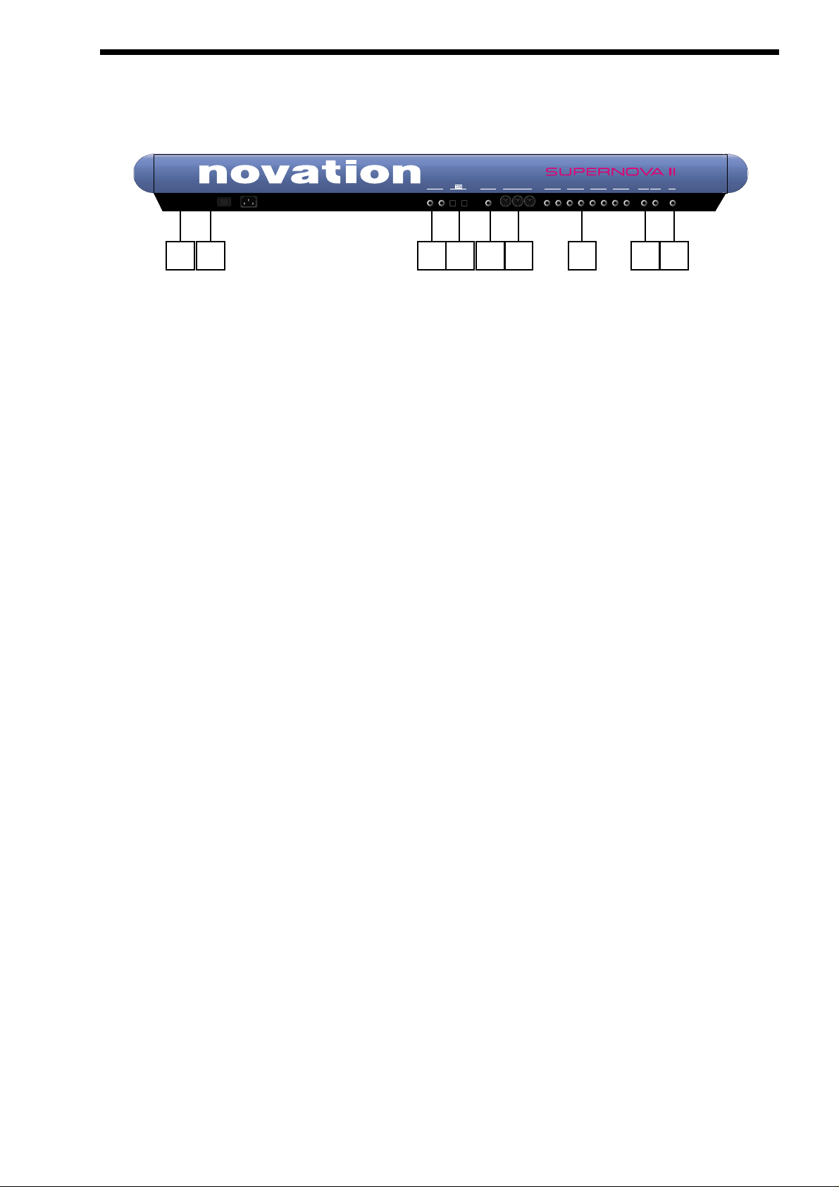
1 - Power On/Off - Switch .
This switch turns the mains power supply in the Supernova II keyboard on and off. Edited and newly-created Programs or
Performances that have not been written into a memory location will be lost when the Supernova II keyboard is switched off. The
edit buffers will not be preserved, so be sure to save edited Programs & Performances to memory before switching Supernova II
keyboard off. Refer to pages 38 & 41 for details of writing Programs and Performances into memory.
2 - IEC Mains Connector.
This socket is for the supplied Mains lead. This socket accepts 110V, 220V & 240V mains supplies at 50 or 60 Hz. This ensures
the Supernova II keyboard will work on any country’s mains supply.
3 - SPDIF Phono In & Out Connectors.
These phono sockets provide SPDIF format digital inputs and outputs supplied when the optional SPDIF/ADATcard is installed.
4 - A D AT Optical In & Out Connectors .
These optical connectors provide ADAT format digital inputs and outputs supplied when the optional SPDIF/ADAT card is installed.
5 - Pedal / Switch 3 Socket .
This 1/4 inch jack socket allows the connection of either an optional footswitch or expression pedal to be connected. The functions
of these sockets are defined in the Global menu.
6 - MIDI IN / MIDI OUT / MIDI THRU Connectors.
The MIDI IN connector is used to receive MIDI Data from an external device.
The MIDI OUT connector is used to transmit MIDI Data to an external device.
The MIDI THRU connector re-transmits MIDI Data received by the MIDI IN socket to an external device.
7 - Master Left & Right / Aux 1 / Aux 2 & Aux 3 Audio Outputs.
The Master Left & Right 1/4 inch Jack sockets deliver a Stereo Line Level output signal for connection to a mixing desk or amplifier. The level of these outputs is controlled by the Master Volume Knob on the front panel.
The Aux 1 1/4 inch Jack sockets deliver a Stereo Line Level output signal for connection to a mixing desk or amplifier. These outputs can be used in addition with the Master Audio Outputs for more flexibility in live and studio applications.
The Aux 2 1/4 inch Jack sockets deliver a Stereo Line Level output signal for connection to a mixing desk or amplifier. These outputs can be used in addition with the Master Audio and the Aux. 1 Outputs for even more flexibility in live and studio applications.
The Aux 3 1/4 inch Jack sockets deliver a Stereo Line Level output signal for connection to a mixing desk or amplifier. These outputs can be used in addition with the Master Audio and the Aux. 1 & 2 Outputs for even more flexibility in live and studio applications.
8 - Input/SW2 & input/SW1 Connectors.
These 1/4 inch Jack sockets provide 2 audio inputs for synthesis, filtering or effect processing or as footswitch inputs. The function
of these sockets is user defined in the Global menu. When used as audio inputs, the sensitivity is user defined in the inputs menu.
9 - Headphones - Socket.
Use this 1/4 inch Jack Socket to monitor the Left & Right output of the Supernova II keyboard via headphones. This output will
drive any type of headphones. The Supernova II keyboard’s headphone amplifier will deliver a louder signal if low impedance
BACK PANEL
3
1 2 3 4 5 6 7 8 9
aux 1aux 2aux 3pedal/switch 3 midi
SPDIF
inout
O I
inout
master
436587thru out in
21
phonesinput/sw1input/sw2
(sustain)
Page 4

SETTING UP
headphones are used (i.e. 8 ohms impedance). Be aware that the sound pressure level obtainable with low impedance headphones could damage hearing.
Connect the Master left & Right Audio Outputs (and the Aux. 1, Aux. 2 & Aux. 3 Audio Outputs if required ) of the Supernova II
keyboard to a suitable amplifier or mixing desk’s stereo inputs and set the Master Volume control on the Supernova II keyboard to
a reasonably high output level ( 9 - 10 ). This will maintain a good signal to noise ratio. Make sure the input volume on your amplifier or mixing desk is initially set to zero.
Make sure that the Supernova II keyboard’s mains switch is in the “OFF” position. Connect the Mains supply with the supplied lead
to the Mains Socket on the Supernova II keyboard. Connect the other end to the mains supply and switch the supply on. The display should now illuminate showing the Performance, Program or Favourite that was selected when the global settings were last
written into memory. Refer to page 47 for details on this function. Now switch on your amplifier and adjust the volume accordingly
whilst playing the keyboard.
The keyboard will be playing the currently selected Performance, Program or Favourite. To listen to all of the Factory sounds, make
sure you are in the Performance, Program or Favourite Mode by pressing the appropriate Performance, Program or Favourite
mode Button. The Keypad section can now be used to call up the different sounds. For details on how to select the different
Performances and Programs, refer to page 33.
4
Page 5
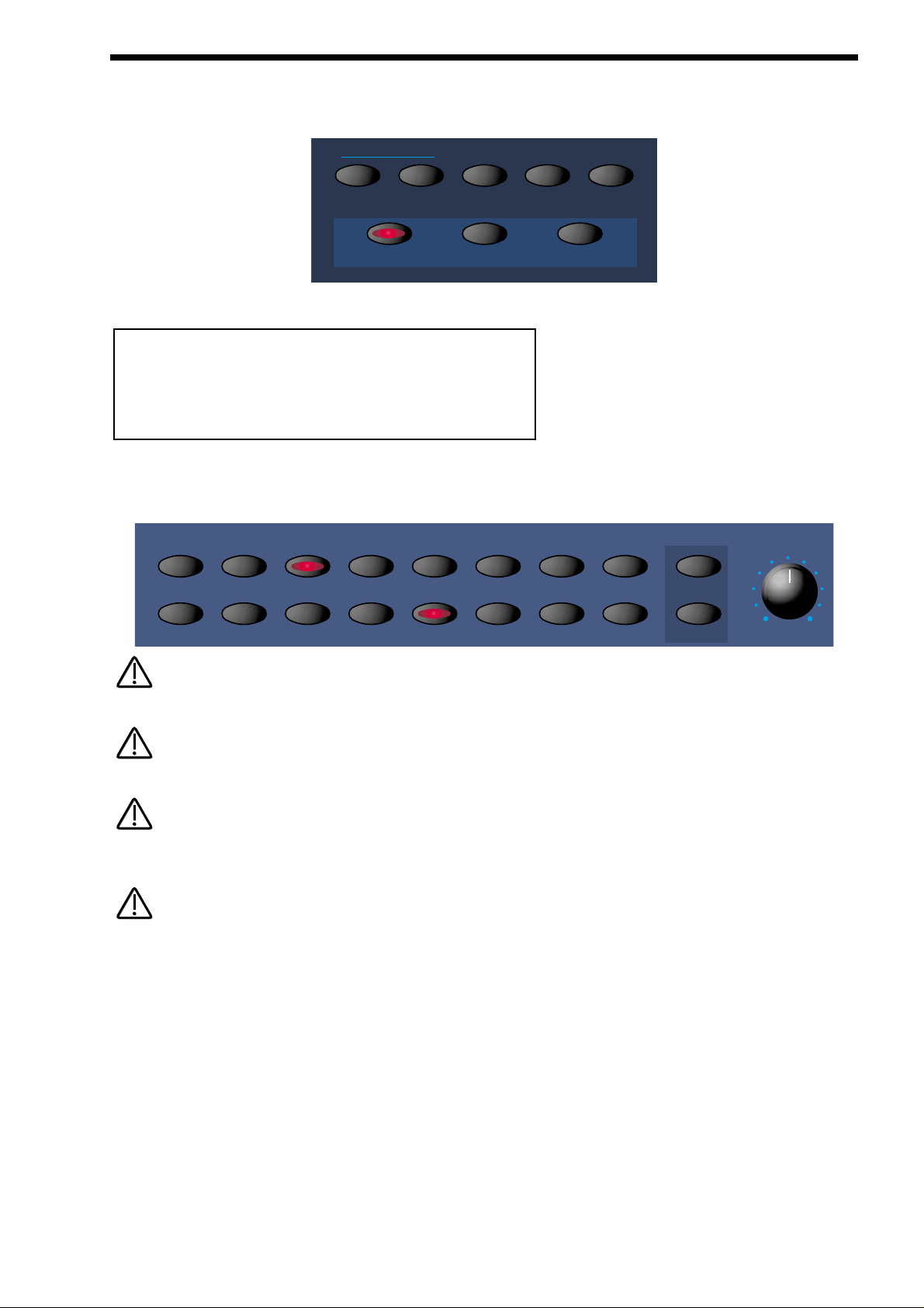
The Demo mode is activated by either pressing the ‘Find’ and ‘Global’ buttons simultaneously or pressing just the ‘Find’ button
while currently within the Global Menu.
When demo mode is activated the display shows :
The Part edit buttons will be flashing to indicate which buttons can be pressed to start a demo. The Display shows which Demo is
currently playing.
Once a demo has finished, the next demo in sequence will automatically start.
Once the last demo has finished playing, the sequence of demos loop and the first demo starts again.
Pressing a Part edit button while the demos are playing, causes the current demo to stop and the new appropriate demo to start
from the beginning. Additionally the current demo can also be selected using the higher Data knob.
A demo can be stopped at any time by pressing the ‘Find’ button again while the demo is playing. Pressing the ‘Find’ button once
more restarts the demos, starting from Demo number 1. A playing demo may also be stopped and Demo Mode exited by simply selecting any normal mode button or selecting any Menu button.
DEMO MODE : Press
Part buttons to play
PLAYING THE FACTO RY DEMO
5
demo tracks
find global
compare assign
performanceprogram
write
favourites
favourites
Part Edit
12345678
solo
mutetune velocity output midi polyphony range special external part level
NOTE:
NOTE:
NOTE:
NOTE:
NOTE:
NOTE:
NOTE:
NOTE:
Page 6
BASIC SETUP
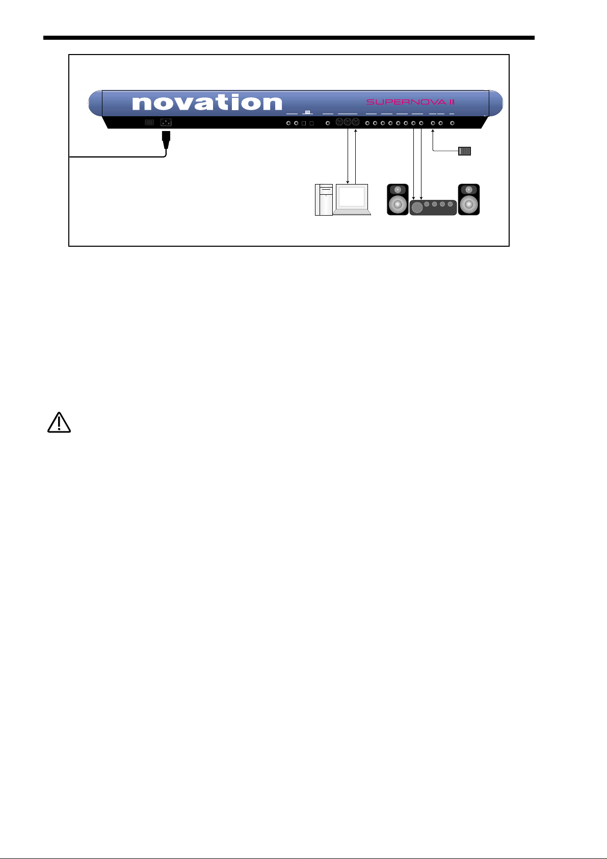
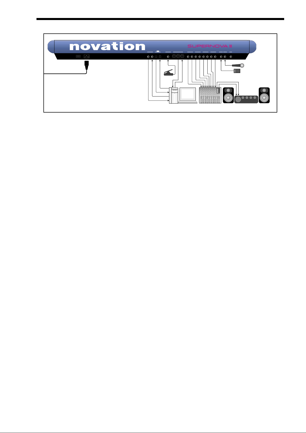
Above is a diagram of the basic way to set-up the Supernova II keyboard. Normally the set-up would be as follows: Connect the
Supernova II keyboard as shown above. Set the “Local On/Off” parameter on page 7 of the Global mode to OFF. Turn the
Computer Software / Sequencer’s “Soft Thru” ( or sometimes called “Echo Back” ) to the “ON” or “Enabled” position. Now when
selecting a “Track” in the computer Software / Sequencer that is assigned to the same channel as the Supernova II keyboard is set
to receive on ( If this is a Performance you can set the receive channels individually for each “Part”. Refer to page 136 for details, If
this is a Program, Programs are played on the “Global MIDI Channel (refer to page 48 for details). Playing the keyboard should
should produce sounds through the Headphones / Monitors.
The Supernova II keyboard can have virtually any parameter controlled via MIDI. The movement of any knob, the pressing of any
button or change to any parameter can be recorded with this setup. These recordings can then be easily edited on a sequencer.
Details on all the controllers and NRPNs (Non Registered Parameter Numbers) used by the Supernova II keyboard can be found
on pages 167 to page 180.
If there are additional keyboards / Modules connected via MIDI, this diagram does not include audio for the keyboards / Modules.
The audio outputs of these devices must also be connected to the mixer.
6
To Mains Supply
aux 1aux 2aux 3pedal/switch 3 midi
SPDIF
inout
O I
inout
MIDI IN
MIDI OUT
master
436587thru out in
21
(sustain)
Audio Inputs
phonesinput/sw1input/sw2
Sustain Pedal
Computer / Sequencer
Amplifer / Mixer and Monitors
NOTE:
NOTE:
Page 7
This is the one of the more advanced ways to set up the Supernova II keyboard. Connect the Supernova II keyboard as shown
above. Set the “Local On/Off” parameter on page 7 of the Global mode to OFF. Turn the Computer Software / Sequencer’s “Soft
Thru” ( or sometimes called “Echo Back” ) to the “ON” or “Enabled” position. Now when selecting a “Track” in the computer
Software / Sequencer that is assigned to the same channel as the Supernova II keyboard is set to receive on ( If this is a
Performance you can set the receive channels individually for each “Part”. Refer to page 136 for details, If this is a Program,
Programs are played on the “Global MIDI Channel”. Refer to page 48 for details.) playing the keyboard should should produce
sounds through the Headphones / Monitors.
The Supernova II keyboard can have virtually any parameter controlled via MIDI. The movement of any knob, the pressing of any
button or change to any parameter can be recorded with this setup. These recordings can then be easily edited on a sequencer.
Details on all the controllers & NRPNs (Non Registered Parameter Numbers) used by the Supernova II keyboard can be found on
pages 167 to page 180.
There are 4 stereo pairs of Outputs connected to the mixer. This allows individual sounds to be processed externally by the mixer
and other outboard equipment. To direct “Parts” of a “Performance” to these separate outputs Refer to page 136 for details.
Additionally, the Supernova II keyboard automatically redirects the effects outputs for the selected part to go to the same outputs
as the part, so even if separate outputs are assigned the associated effects follow automatically.
Additionally a microphone is connected to Input/SW1 & this allows external signals to be processed by the synthesis engine (
including filtering ) and/or effects processors and Vocoder of the Supernova II keyboard. In fact virtually any type of signal can be
used by the Supernova II keyboard, as the gain of the 2 inputs can be adjusted from Microphone level through to Studio levels
(+4dBm ). Refer to page 100 for details on how to use the inputs. The inputs can also double as Footswitch inputs. A footswitch is
shown connected to Input/SW2. The function of this socket is determined in the Global Menu. Refer to page 52 for details.
An expression pedal input is also shown, allowing a optional pedal to be connected. Virtually any parameter can be controlled via
the expression pedal using the “Pedal/breath” parameter on page 4 of the Global menu. Alternatively, this socket can be used as a
footswitch input. The function of this Pedal/Switch input can be user determined in the Global Menu. Refer to page 53 for details.
An Optional Digital I/O card can be fitted to the Supernova II keyboard providing an ADAT Optical & SPDIF Coaxial digital Input
and output. When connected to suitable hardware (such as a KORG 1212 PCI Card or any similar digital audio card for computers
or a digital Mixer such as the Yamaha 02R with suitable digital interfaces), the Supernova II keyboard can transfer sound digitally.
This allows the Supernova II keyboard to integrate easily within a modern digital studio and allows some unique possibilities such
as separate filtering and effects processing of 8 ADAT tracks of audio from a computer hard disk recording system simultaneously,
and then digitally transferring the processed tracks back to the computer via the ADAT out, or alternatively using the Supernova II
keyboard as an I/O system as there are 2 analogue inputs & 8 analogue outputs.
aux 1aux 2aux 3pedal/switch 3 midi
436587thru out in
master
21
inout
SPDIF
inout
phonesinput/sw1input/sw2
(sustain)
Sustain Pedal
Microphone
To Mains Supply
Amplifer / Mixer and Monitors
Audio Inputs
Mixing Console
MIDI IN
ADAT IN
Pedal
MIDI OUT
ADAT OUT
SPDIF IN
SPDIF OUT
Computer / Sequencer
O I
A D VANCED SETUP
7
Page 8
ABOUT ANALOGUE SYNTHESIS
OSCILLATO R S - pitch
To understand synthesis, it is necessary to have some understanding about sound itself. Sound is a vibration or oscillation. These
vibrations create changes in air pressure which is picked up by your ears and perceived as sound. When dealing with musical
sounds, the vibrations or oscillations occur at regular intervals and are perceived as the “Pitch” or “Frequency” element of a sound.
The simplest musical sound is actually a sine wave because it contains only one “Pitch” and is perceived as a very “Pure” tone
similar to a whistle. Most musical sounds consist of several different “Pitches” or “Frequencies”. The lowest is referred to as the
“Fundamental” and determines the perceived “Pitch” of the note. The other frequencies present are called “Harmonics”, and in
musical sounds usually occur in multiples of the fundamental frequency. i.e. if the fundamental note is 440Hz then a musical harmonic series would be 2nd harmonic = 880Hz, 3rd harmonic = 1320Hz, 4th harmonic = 1760Hz, 5th harmonic = 2200hz etc. The
number and loudness of these “Harmonics” determines the “Timbre” or “Tone” of a sound. This gives a sound character and is why
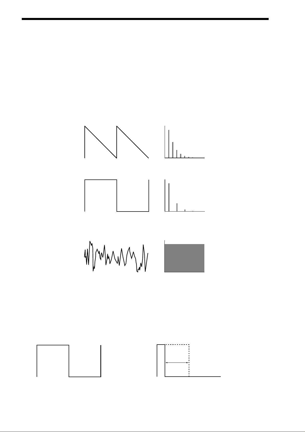
a violin sounds different from a guitar, and a piano sounds different again. In an Analogue synthesiser, you have the choice of several different waveforms. Each waveform has different amounts of harmonics and so the “Timbre” of each one is quite different.
Below are descriptions of some of the waveforms and indications on what they can be best used for.
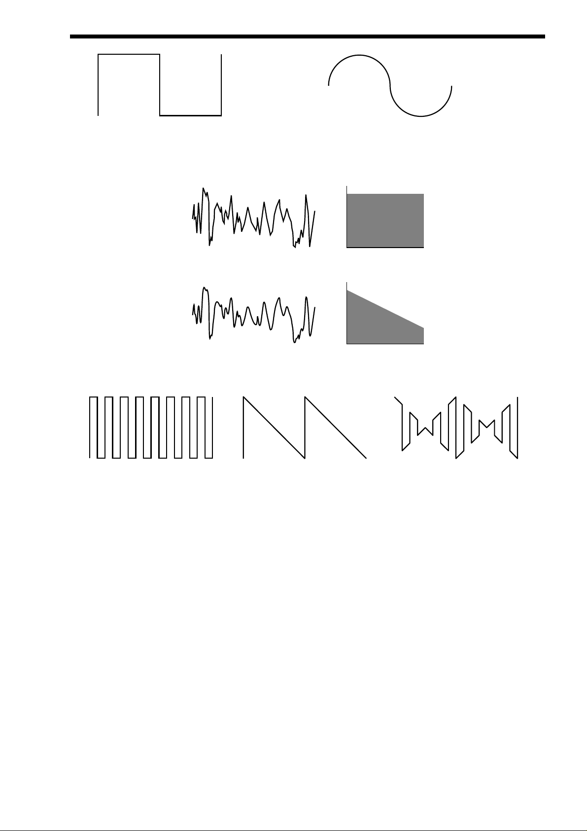
Sawtooth waves have all the harmonics of the fundamental frequency. As you can see, every harmonic has half the amplitude of
the previous one. This sound is pleasing to the ear and is useful for basses, leads or synthesising stringed instruments.
Square waves have only the odd harmonics present. These are at the same amplitudes as the odd harmonics in a saw wave.
Square waves have a hollow / metallic sound to them and so are useful in creating unusual synthesiser and oboe-like sounds.
White noise has no fundamental and so all harmonics are the same value. This wave can be used by itself to synthesise explosions or wind, and when used in conjunction with other waveforms can be used to create the illusion of “Breath” in an instrument.
P W M (PULSEWIDTH MODULATION )
The choice of waveform is important as it determines the basic “Timbre” of the sound you are making. There are additional methods of synthesis that allow more harmonics to be generated. The First of these is Pulse Width Modulation. ( PWM for short ).
Essentially the duty cycle of the normally symmetrical square wave is varied. This means the wave form goes from a Square wave
to a Pulse wave like so:
This has a very pleasant “thickening” chorus like effect and is often used in Pad type or String section type sounds.
8
Level
Level
Square Waveform
1234567
Harmonics
Level
Noise Waveform
1234567
Harmonics
Variable Width
Square Waveform
Pulse Waveform
Page 9
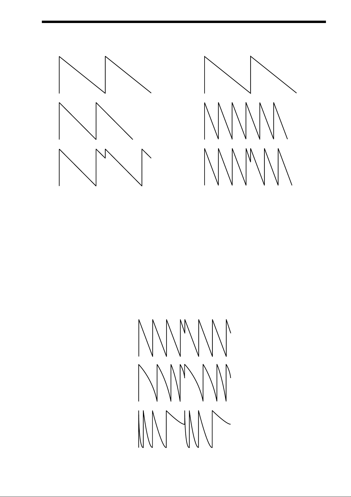
Additionally there is a synthesis method called Oscillator sync. This takes two oscillators, using one ( the Master ) to reset the other
( The Slave ) each time it starts a new cycle. The effect is most noticeable when the two oscillators are out of tune as shown
below.
This Sync Effect creates very piercing and metallic sounds, often used a lot as lead sounds. It is worth noting that the Supernova II
keyboard does not require 2 oscillators to create this effect. The Sync “Effect” is created by the Analogue Sound Modelling process
without the need for a Sync Oscillator. There is merely a “Sync” parameter that creates the classic Sync Effect. This means that
each of the 3 oscillators in one Supernova II keyboard “voice” can be independently Sync’ed as if there were 3 Master and 3 Slave
oscillators.
Analogue Sound Modelling technology also enables the creation of some new “Sync” related parameters that are not found on
analogue synthesisers. These are “Key Sync”, “Sync Skew” & “Formant Width”.
Normally on an analogue synthesiser, even though the Master and Slave oscillators are detuned relative to each other, they both
track keyboard pitch equally. i.e. if you play notes one octave apart, both the Master and the Slave oscillator will be transposed one
octave. On the Supernova II Keyboard, “Key Sync” allows the virtual slave oscillator to have its pitch tracking adjusted independently. This means that the “Sync Effect” will change as you play different notes up and down the keyboard.
Sync Skew manipulates the frequency of the “virtual” slave oscillator within one cycle of the master oscillator. The result is that the Sync
Effect seems to have a higher frequency at the end of each cycle with positive modulation and at the start of the cycle with negative modulation. This parameter makes the sync waveform sound even harsher. This is particularly good for aggressive lead sounds.
ABOUT ANALOGUE SYNTHESIS
9
Osc1( Master )
Osc2 ( Slave )
Sync Waveform
Osc1( Master )
Osc2 ( Slave )
Sync Waveform
Normal Saw Sync Waveform
Positive Skew on a Saw Sync Wave
Negative Skew on a Saw Sync Wave
Page 10
ABOUT ANALOGUE SYNTHESIS
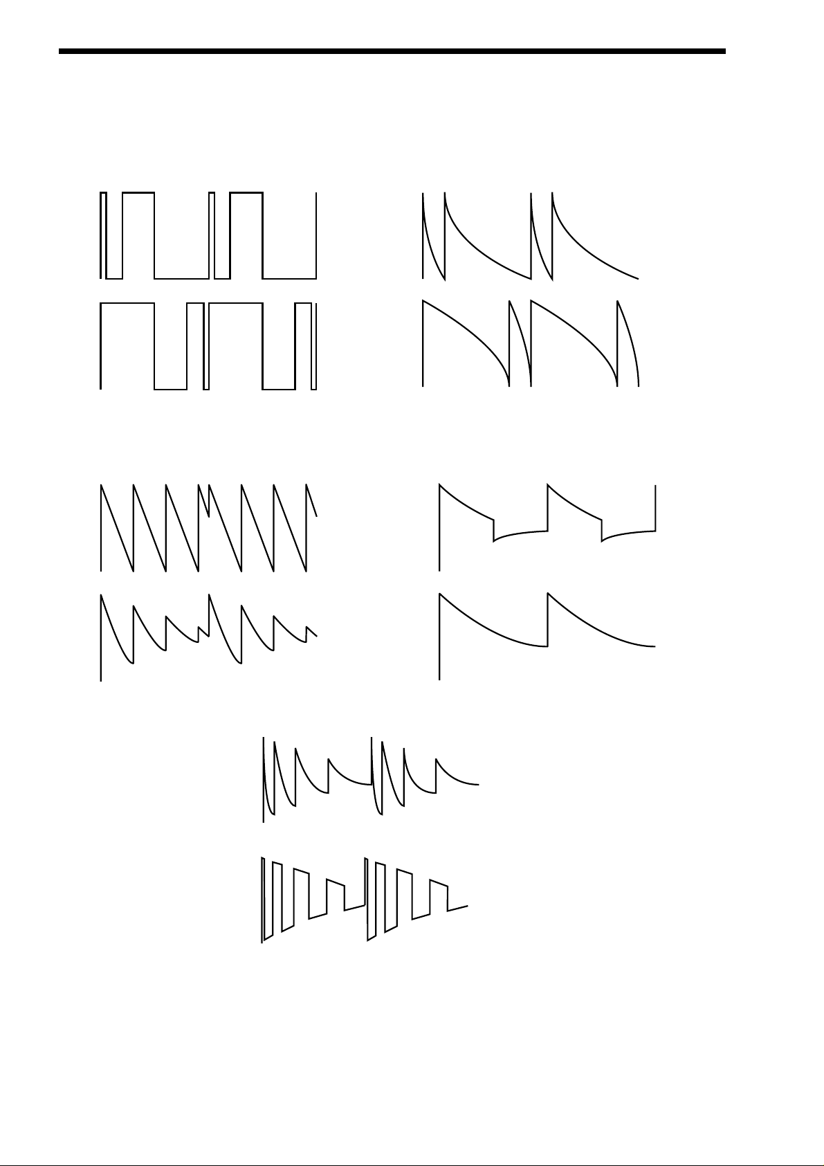
Sync Skew also effects the standard Square and Saw waveforms. The effect is to “sqwash” the waveform at the end of its cycle
with positive modulation, sqwashing the waveform at the beginning of the cycle. On a square wave, moderate amounts of this
effect produce similar effects to Pulse width modulation except width modulation over 100% can be achieved, allowing many cycles
to be “sqwashed” into one original one. This can also be described as Frequency Modulation within the cycle and so mimics classic
“Cross Modulation” with a Saw wave. This can produce effects similar to Sync but when this parameter is used in conjunction with
Formant Width, the results can be very different. Below are examples of Sync Skew on standard Square and Saw waveforms. Note
how the wave is sqwashed at one end and how more than one cycle has been sqwashed into the original cycle.
Formant width is a parameter that controls the level of the cycles of the “virtual” slave oscillator. This can be used to simulate resonance within the oscillator itself by using the “Harden” parameter to smooth out the sharp edges of this wave form. The effect is to
reduce the level of every successive slave cycle. Additionally this parameter has an effect on the normal Saw and Square waveforms, boosting the treble content of these waves.
Both Sync Skew and Formant Width can be used in conjunction to create yet even more waveforms. Below are examples.
Analogue Sound Modelling technology allows even more control over the waveform. Once you have selected your basic oscillator
waveforms, you can further modify them using a “Hardening” process. At low values, the “Hardness” parameter rounds off all the
“Sharp” edges of the waveform, thereby reducing its harmonic content. Below is an example of what the “Harden” parameter does
to a Square wave.
10
Negative Skew on a Square Wave
Positive Skew on a Square Wave
Negative Skew on a Saw Wave
Postive Skew on a Saw Wave
Sync Waveform
Sync Formant Width Waveform
Formant Width on a Square Wave
Formant Width on a Saw Wave
Negative Skew & Formant Width on a Saw Wave
Negative Skew & Formant Width on a Saw Wave
Page 11
The Harden parameter is completely variable and can reduce a square wave to only one harmonic, producing a Sine wave. The
Harden process can also be applied to the noise generator providing control over the harmonic content of the noise. Below is an
example of what the “Harden” parameter does to Pink Noise.
Finally there is Ring modulation. This uses two oscillators but instead of adding them together like in a mixer, they are multiplied
together. This is very similar to FM and produces the kind of effect shown below:
The Ring Modulation effect creates metallic and bell-like sounds, often used generally for lead sounds, but if used subtly, can be
used to produce Electric Pianos etc. If used radically, Ring Modulation can produce unusual sound effects.
All these methods further enhance the basic Oscillator waveforms to provide further waveforms or a useful mix of harmonics. Once
the waveforms have been selected, you can then “fine tune” the harmonic content of the mixture of different waveforms by passing
them through a “Filter” to remove unwanted harmonics. The filter in an Analogue synthesiser is a very powerful “Tone Control”. A
tone control on a stereo can alter how things sound, but it cannot change the style of music being played on the record. Similarly,
the filter in a synthesiser can alter the “tone” of a sound but is restricted by the basic “Timbre” of the waveforms. For this reason,
several waveforms are available at once (using different Oscillators) and you can “Mix” them together to provide more harmonically
rich waveforms. Below is a diagram showing the signal path in the Supernova II keyboard and the waveforms at various locations.
ABOUT ANALOGUE SYNTHESIS
11
Square Waveform
Softened Square Waveform
Level
Noise Waveform
Softened Noise Waveform
1234567
Harmonics
Level
1234567
Harmonics
Osc1
X
Osc2
=
Ring Modulated Waveform
Osc1 x Osc2
Page 12
ABOUT ANALOGUE SYNTHESIS
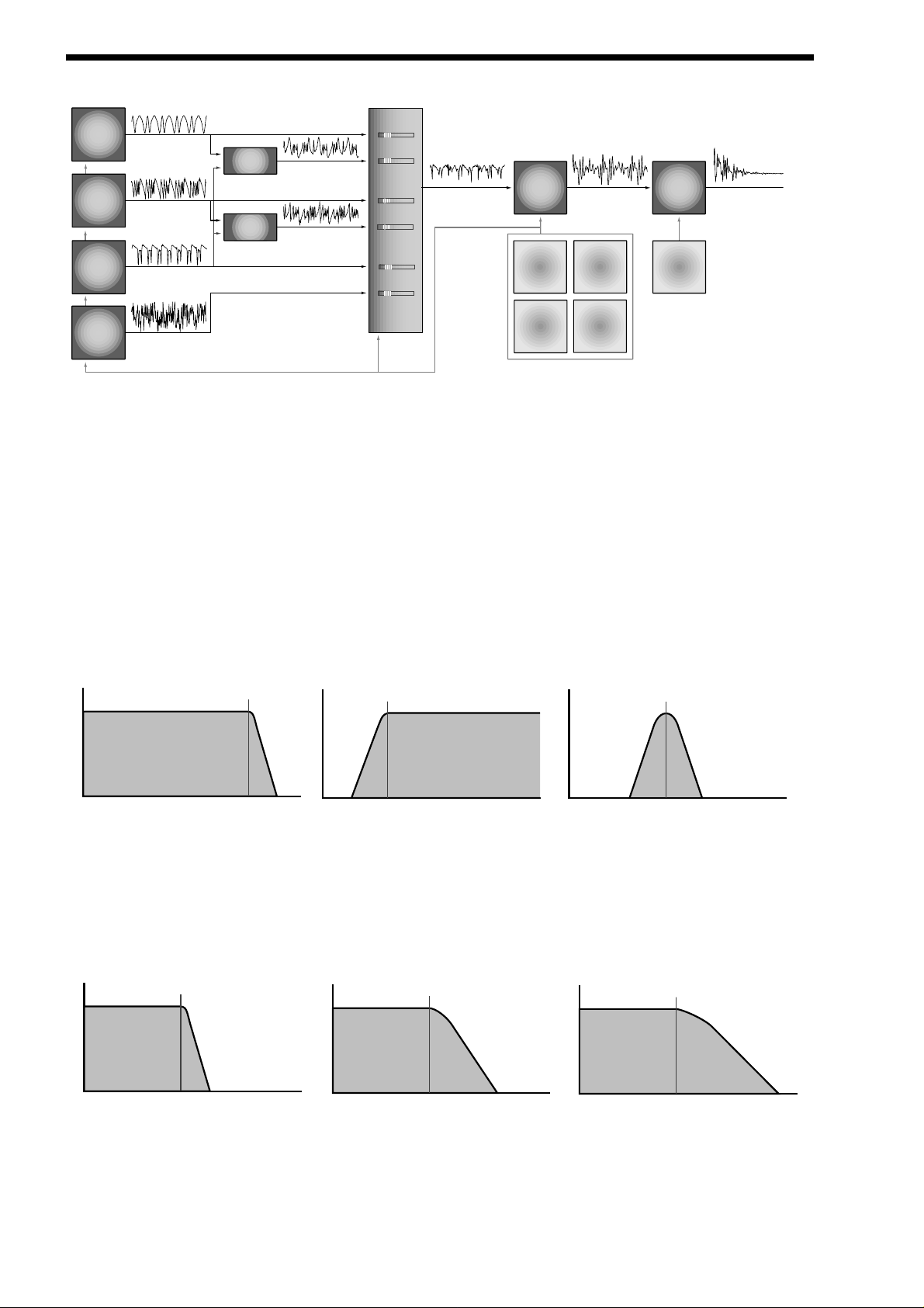
Different waveforms are being produced by different Oscillators using different techniques. The Oscillators, Ring Modulators & the
Noise Generator can all be mixed together and fed to the Filter. The filtered signal is then in turn fed to the Amplifier. Oscillator 1 is
shown using a Square wave modulated by Sync Skew and then hardened to create a sine-like wave (except it has an extra bump
in it). This produces a pure, Whistle like sound. Oscillator 2 is shown using a Saw wave modulated by Sync Skew and Sync, producing a Harsh sound. Oscillator 3 is shown using a Square wave modulated by Sync Skew and Formant Width to produce a
bright PWM like waveform. The 1*3 Ring modulator and 2*3 Ring modulator are shown producing complex waveforms. These,
along with all the Oscillators and Noise generator are fed to the Mixer.
FILT E R - tone
There are several different types of filter. These are Low Pass Filter, High Pass Filter& Band Pass Filter. The Low Pass Filter
allows harmonics below a set frequency to pass through the filter (hence the term Low Pass). The High Pass Filter allows harmonics above a set frequency to pass through the filter (hence the term High Pass). The Band Pass Filter allows a band of harmonics
at a set frequency to pass through the filter. The harmonics above and below the set frequency do not pass through (hence the
term Band Pass). Below are the frequency response curves of the three types of filters.
Additionally, the slope of the curve at which the filter rejects unwanted harmonics can be altered. The effect is similar to a “Q” control on a parametric EQ. In the 12dB position, the Cutoff Frequency slope is less steep, so the higher frequencies are not attenuated (reduced) as much as they are in the 24 or 18dB positions. This makes the resulting filtering in the 12dB position more subtle
than the 24 or 18dB positions, which should selected if the Cutoff Frequency is to be made more obvious. The slope is measured
in dB per Octave. Below are the response curves of a Low Pass Filter with 24, 18 & 12 dB per Octave slopes.
All these filters have a Resonance parameter. This has the effect of emphasising harmonics at the cutoff frequency of the filter.
This is very useful for creating large tonal differences to a basic waveform. The effect is shown below as frequency response
curves when resonance is applied in the Filter.
12
Signal Path Diagram
Osc 1
Osc 2
Osc 3
Noise
Gen
Osc 1 output
( Sq wave Softened with
+ve Skew )
Osc 2 output
( Saw wave Synced with
+ve Skew )
Osc 3 output
( Sq wave Synced with
+ve Skew & Formant width )
Pink noise output
Osc 1*3
Ring Mod
Osc 2*3
Ring Mod
Ring Mod output
Ring Mod output
MIXER
Osc 1 level
Osc 1*3 level
Osc 2 level
Osc 2*3 level
Osc 3 level
Noise level
Mixer output Filter output Amp output
Filter Amp
Env 2
LFO 1
Env 3
LFO 2
Env 1
Cutoff
Volume
Frequency
Frequency
Low Pass Filter Responce Curve
Volume
High Pass Filter Responce Curve
Cutoff
Frequency
Frequency
Cutoff
Volume
Frequency
Frequency
Band Pass Filter Responce Curve
Volume
Cutoff
Frequency
Volume
Cutoff
Frequency
Volume
Cutoff
Frequency
Frequency
24db/oct LPF Responce Curve
18db/oct LPF Responce Curve
Frequency
Frequency
12db/oct LPF Responce Curve
Page 13
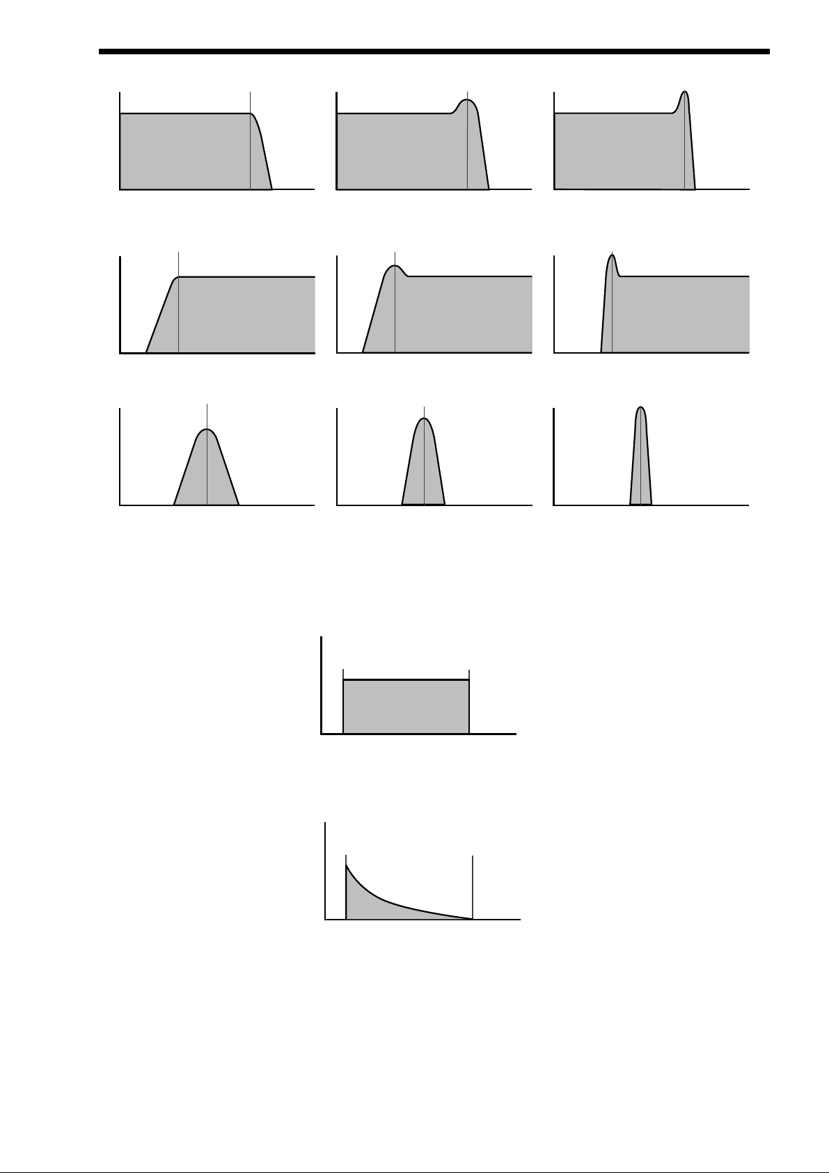
AMPLIFIER - volume
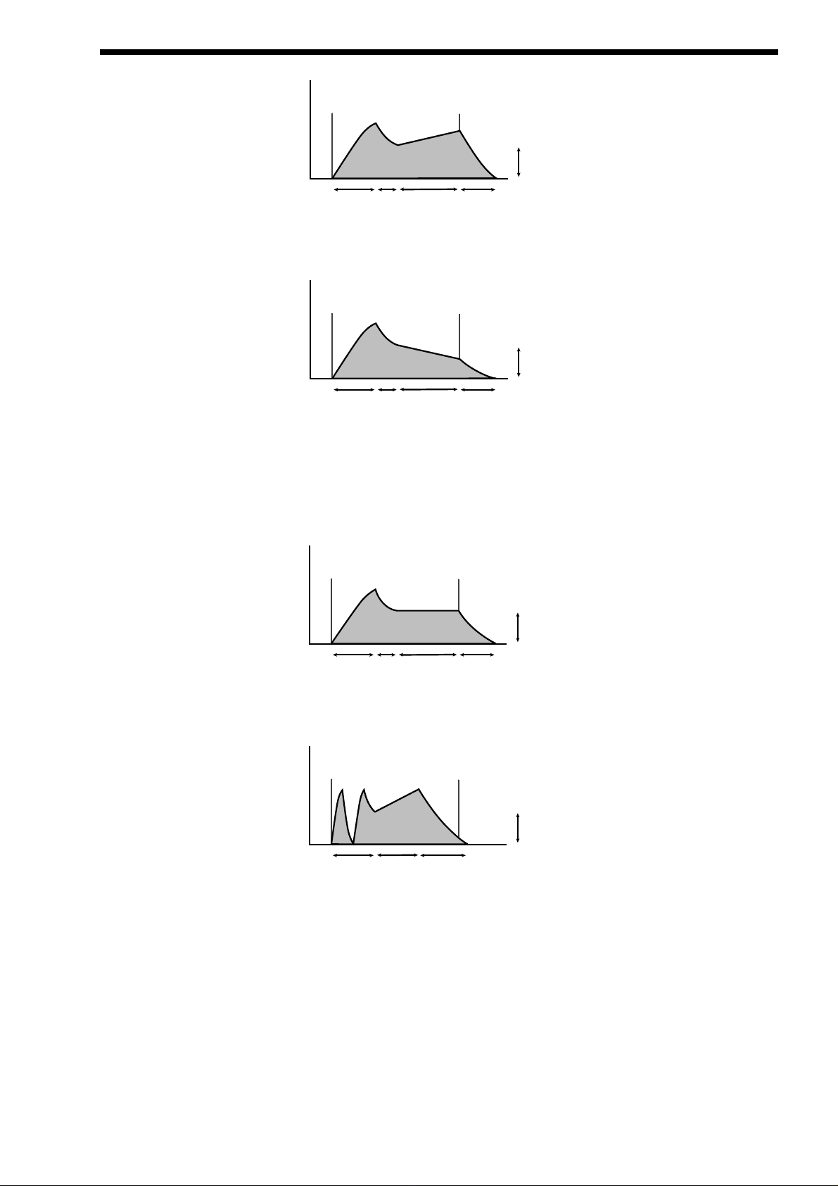
The last major process that makes up a sound is its “Volume”. The “Volume” of sounds often vary as time goes by, and so an
Organ has very different volume characteristics than that of a Piano or String section. See the following diagrams for details.
The “Organ” can be seen to go to full volume instantly when a key is pressed and then stay there until the key is released at which
point the volume drops instantly to zero.
The “Piano” can be seen to go to full volume instantly when a key is pressed and then gradually fall back down to zero over several seconds while the note is held.
ABOUT ANALOGUE SYNTHESIS
13
Cutoff
Frequency
Volume
No Resonance Mid Resonance High Resonance
Volume
Frequency
Cutoff
Frequency
Frequency
Volume
Low Pass Filter with Resonance Responce Curves
Cutoff
Frequency
Volume
No Resonance Mid Resonance High Resonance
Volume
Frequency
High Pass Filter with Resonance Responce Curves
Volume
Cutoff
Frequency
Volume
No Resonance
Cutoff
Frequency
Frequency
Cutoff
Frequency
Volume
Volume
Mid Resonance
Cutoff
Frequency
Frequency
Frequency
Cutoff
Frequency
Cutoff
Frequency
Frequency
Frequency
Frequency
Band Pass Filter with Resonance Responce Curves
Volume
Key "On"
Key "Off"
Time
"Organ" Type Volume Response Curve
Volume
Key "On"
Key "Off"
Time
"Piano" Type Volume Response Curve
Page 14
ABOUT ANALOGUE SYNTHESIS
The “String section” volume curve can be seen to go to full volume gradually over several seconds when a key is pressed and then
stay there until the key is released, when gradually over a couple of seconds the volume drops to zero.
These volume curves are called “Envelopes”. In an Analogue synthesiser, “Envelope Generators” are used to recreate them.
Envelope Generators have 4 main parameters which are used to adjust the shape of the envelope. See the diagram below:
Attack time is used to adjust the time it takes when the key is pressed for the envelope to go from zero to full value ( Fade in ).
Decay time is used to adjust the time it takes for the envelope to go from full value to the value set by the Sustain level. ( Piano
like decay of volume )
Sustain level is used to set the level that the envelope remains at while the key is held down.
Release time is used to adjust the time it takes when the key is released for the level to go from the sustain value to zero. ( Fade
out )
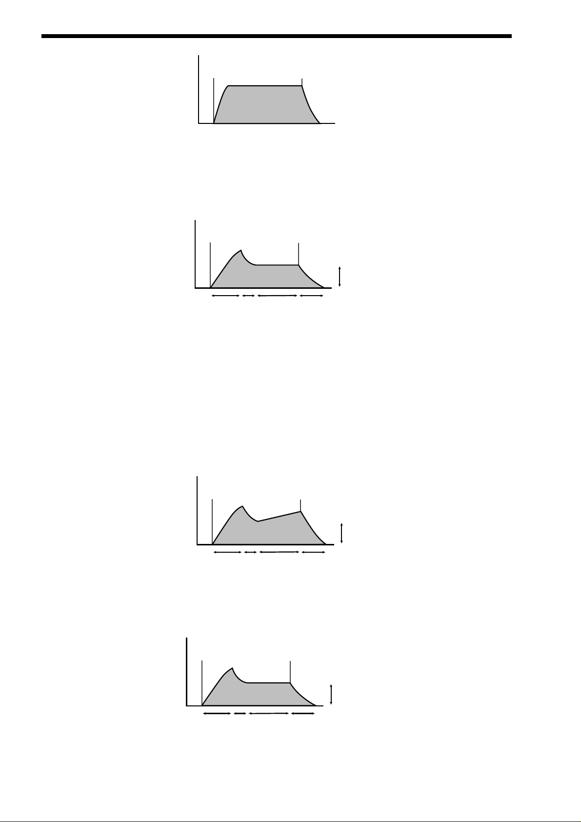
The Supernova II keyboard also offers additional envelope features to the classic ADSR types allowing even more flexibility, see
the diagram below:
In addition to the Attack, Decay, Sustain & Release parameters there are also 3 new parameters. These are:
Sustain Rate which is used to control the slope of the “Sustain” phase of the envelope. When this parameter is set to zero, the
curve is normal like so:
When this parameter has a +ve value, during the “Sustain” phase of the envelope, the Sustain value will rise to full at a “Rate”
determined by this parameter as can be seen below:
14
Volume
Key "On"
Key "Off"
Time
"String Section" Type Volume Response Curve
Volume
Key "On"
Decay
Time
Infinite Sustain
Time with
no Sustain Rate
Attack
Time
ADSR Type Volume Response Curve
Key "Off"
Sustain level
Release Time
Volume
Key "On"
Attack
Time
Decay
Time
Infinite Sustain
Time with
+ve Sustain Rate
Key "Off"
Sustain level
Release Time
ADSR Type Volume Response Curve
Volume
Key "On"
Key "Off"
Sustain level
Decay
Time
Infinite Sustain
Time with
no Sustain Rate
Release Time
Attack
Time
Page 15
Low values like +01 will produce a very slow rise. High values will produce a quick rise to full intensity. When this parameter has a
-ve value, during the “Sustain” phase of the envelope the Sustain value will fall to zero at a “Rate” determined by this parameter as
can be seen below:
Low values like -01 will produce a very slow fall, while high negative values will produce a quick fall to zero intensity.
A-D Repeat allows the Attack & Decay phases of the envelope to be looped, producing repeated cycles of Attack & Decay curves.
This is fully adjustable from Off ( normal ADSR operation ), up to 126 repeats or Infinity.
Sustain Time which is used to control how long the “Sustain” phase of the envelope will last. When this parameter is set to 127 (
infinite ) the curve is normal like so:
When this parameter is set to anything less than 127 the “Sustain” phase has a defined time duration and can be adjusted from
very long to very short. This means the “Sustain” phase may end before the key played is released, at which point the “Release”
phase will start automatically. Below is an example of all 3 new parameters working together:
Summary
An Analogue Synthesiser can be broken down into three main elements.
1 - The Oscillator is the part of a synthesiser that generates “Waveforms” at a certain “Pitch”.
2 - The type of “Waveform” selected in the Oscillator & the settings of the “Filter” determine the “Tone” of the sound.
3 - The sound is then passed through an “Amplifier” which is controlled by an “Envelope Generator”. These alter the
“Volume” of a sound over time.
ABOUT ANALOGUE SYNTHESIS
15
Volume
Key "On"
Attack
Time
Decay
Time
Infinite Sustain
Time with
+ve Sustain Rate
Key "Off"
Sustain level
Release Time
Volume
Key "On"
Attack
Time
Decay
Time
Infinite Sustain
Time with
-ve Sustain Rate
Key "Off"
Sustain level
Release Time
Volume
Key "On"
Attack
Time
Decay
Time
Infinite Sustain
Time with
no Sustain Rate
Key "Off"
Sustain level
Release Time
Volume
Key "On"
A/D Repeat
set to 1
Short Sustain
Time with
+ve Sustain Rate
Key "Off"
Sustain level
Release Time
Page 16

ABOUT ANALOGUE SYNTHESIS
All of these three main elements can be controlled by various methods. For example:
The “Pitch” of a note can be played on a keyboard or a synthesiser. Additionally it can be manipulated in real time using the “Pitch
Bend Wheel” to create “Slides” and “Bends” in pitch. LFOs ( low frequency oscillators ) can be used to “Wobble” the pitch of a note
at a specific rate creating a “Vibrato” effect. An Envelope Generator can also be used to “Slide” the pitch in an automatic way.
The Filter can be manipulated by LFOs to vary the “Tone” of a sound at a specific rate creating a “Wah Wah” type of effect. An
Envelope Generator can also be used on the Filter so that the “Tone” of a sound changes over time. A feature called “Keyboard
Tracking” can also be used on the Filter so that the “Tone” of a sound changes depending on the note being played.
The Amplifier can be manipulated by Envelope Generators so that changes in the “Volume” of a sound over time can make the
sound short and percussive or more like a piano, or even like an organ. Additionally the “Velocity” at which you hit the keys can
also be used to manipulate volume making a sound more “expressive”.
The elements that manipulate these three main synthesis elements are called “Modulation Sources”.
The Supernova II keyboard features 3 Envelope generators and 2 LFOs ( Low Frequency Oscillators ) as Modulation “Sources”. In
addition to these modulators, Velocity (the dynamics of your keyboard playing. i.e. ppp to fff ), Aftertouch ( Pressure on the keyboard while note(s) are held ) and the Modulation Wheel are included as additional “Sources” of modulation signals in a
“Modulation Matrix”. This allows almost any “Source” to modulate a given parameter. It is even possible to have combinations of
different “Sources” modulating one parameter simultaneously. In the Supernova II keyboard this has been neatly arranged on the
front panel so that accessing all the possible combinations of modulation is quick and easy. Below is the Modulation Matrix for the
Oscillator section.
Oscillator Modulation Matrix
Simply by selecting the desired “Source” ( using the row of buttons on the right ) and the desired “Destination” ( using the row of
buttons on the left ), the “Level” or “Mod Depth” knobs allows the creation of complex modulation setups easily. On older modular
Analogue Synthesisers this was done with “Patch” leads that physically connected the “Sources” and “Destinations” together.
This allows some very powerful performance features to be implemented. i.e. It is possible to sweep the “Sync” effect, “Harden”
effect, Pulse Width Modulation and alter the Mix of all three oscillators independently plus open the Filter Cutoff Frequency, Reduce
the Filter Resonance, add lots more Distortion and Delay and reduce the Chorus and Reverb - all by simply moving the Mod Wheel
forward! With the Modulation Matrix, relationships such as these are quick to set up and will transform a “static” sound into one
with real “hands on” control and flexibility.
This is where most synthesisers end. However, the Supernova II keyboard also features a very powerful Effects section. It could be
said that effects are as much “part” of a sound as the raw sound itself. Some of the larger old Analogue systems had built in spring
reverb. And with the development of DSP technology, digital effects have become available in modern synthesisers. However,
when in a “Multimbral” application, many modern synths pass all the sounds through one set of effects, compromising flexibility.
In the Supernova II keyboard, a block of 7 effects is part of the “Program” and can be considered to be part of the synthesis
engine. These effects include Distortion, EQ, Reverb, Chorus/Flanger/Phaser, Delay, Panning & Comb Filter effects. These can
simulate “Real World” effects like Echo and Room Reverberation etc. or they can be used to just do really weird things to your
sound! For details on what each effect does and how best to use them, refer to the About Effects section of this manual on page
20.
The best thing to do is just get in there and tweak those knobs, after all that’s why we put them there! Experiment and you’ll soon
be creating your own sounds. Nothing beats hands-on experience when learning how to make the most of the Supernova II
Keyboard.
mix
pitch
width
sync
hardness
lfo 1
lfo 2
env 2
env 3
wheelmod
level
destination source
modulation
16
Page 17

Basic Theory
Earlier in this manual we were introduced to the basics of subtractive synthesis and became familiar with terms such as harmonics,
timbre, waveforms and oscillators. FM Synthesis is the technique of using one waveform ( Oscillator ) to Frequency Modulate - FM
- another to produce a resultant more harmonically complex waveform.
For purposes of illustration we will assume that the oscillators are producing sine waves.
As we have already discovered, it is the CHANGE in harmonics over time that starts to make a sound interesting to our ears. In
FM synthesis, an envelope generator is inserted between the modulator and carrier waveforms. This gives control over of how
much Frequency modulation is taking place with respect to time.
Adding this envelope makes the basic FM building block look like this
We can see that the output waveform starts off as the same as the carrier, becomes more complex (HARMONICS ARE ADDED)
as the amount of FM modulation increases via the envelope, and then returns to a simple wave again as the envelope decays.
THE TIMBRE OF THE WAVEFORM IS CHANGING WITH TIME. This is the opposite of subtractive synthesis where often a LOW
PASS FILTER is used to REMOVE HARMONICS.
To complete this simple synthesizer, we need to add one further envelope to control the volume of what we are hearing. The complete building block will now look like this.
ABOUT FM SYNTHESIS
17
Osc 1- Modulator
Modulation level = 0 = 30
Osc 3- Carrier
Output Waveform
= 90
Osc 1- Modulator
Envelope
modulation
level = 20
Osc 3- Carrier
Output Waveform
Modulator
Env - used to
control FM
modulation
amount
Carrier
Env - used to
control amplitude
of sound over
time
Output
Page 18

ABOUT FM SYNTHESIS
Yamaha popularised FM synthesis in the 1980’s with the famous DX7 synthesiser.The basic building block of the original Yamaha
machine was referred to as an OPERATOR. An operator is just one oscillator with one envelope generator that can control the output level of the Oscillator.
Referring to our simple synthesiser in the diagram above we can outline the different sections and see that it comprises of two
blocks, each one containing one oscillator and one envelope. This is known as a 2 OPERATOR SYSTEM in DX7 Language.
The DX7 had six operators and these were presented to the user in preset combinations referred to as ALGORITHMS. This terminology of OPERATORS & ALGORITHMS immediately presented users of this new digital technology with a mystifying machine
interface, thus creating original sounds was very often left to professional programmers. We will attempt to make things clearer with
the SUPERNOVA II so you may gain the knowledge to create your own FM sounds.
Programming of your own FM sounds using the Supernova II keyboard.
In any one PROGRAM of the Supernova II keyboard, we can make up to 3 OPERATORS using the oscillators and envelopes
available. We can also add a noise waveform for special effects & Drum/Percussion sounds. For simplicity, most of the factory presets use the same structure as in the diagram below.
A Noise waveform maybe substituted for Osc1 or Osc2
Many musical instruments contain much of the detailed sonic information during the first few moments that the instrument is
plucked, struck or blown. For example, when a Xylophone is struck, during the small amount of time after the beater has made
contact with the wood it will resonate and contain many harmonics. The sound will then settle down to a more periodic waveform.
The easiest way to learn and understand FM is to study a few of the factory presets. So lets start with the Xylophone
Select the FM sound Program H056"FMpt Xylo Lo".
When manipulating FM sounds, most of the "tweaking" will be done using the envelope section and oscillator section.
Because we are now using an additive form of synthesis, it is not really necessary to use the filter section (remember FM
synthesisadds harmonics instead of subtracting them). However, the Filter may still be used to enhance the sound further if
required.
18
perator 1
perator 2
Output
Osc1
Env3
Osc3
Env1
Amplifier
Operator 1
Operator 3
Output
Osc2
Env2
Operator 2
Page 19

When using the Supernova II keyboard for FM synthesis it is important to note that it is ALWAYS Oscillator 3 that is heard as an
output to the mixer section. If you are creating sounds from scratch, we recommend using the program H126 “FM Init Program” as
a starting point, as in this Program all the oscillators are set to sine waves and only oscillator 3 has its mix level turned up.
Referring to the graphic above, we have Oscillator 3 doing the "Body" of the sound. We then have Oscillator 1 via env3 Modulating
Oscillator 1 for a small amount of time to simulate the effect of the beater. To hear just the body of the sound, press "osc3" in the
Oscillator Section and press "solo". - Make sure that the button "fm" under the 1*3 is NOT LIT. Play the keyboard and listen to the
sound. You are hearing a softened square wave that is in fact a sine wave. Whilst playing the keyboard, press the "hardness" button and slowly rotate the "Level" knob. Notice how the sound becomes harder. Turn the knob back so that the hardness level is
zero. Now press the "fm" button. You can hear the FM effect of Oscillator 1 coming in via envelope 3. The extra harmonics are now
audible at the start of the sound and it resembles a real Xylophone.
The amount of time in which FM is taking place and the FM intencity is controlled by Env3. Env3 is allowing an amount of
Oscillator 1 to FM Oscillator 3. Experiment by selecting env3 in the Envelopes section and varying the decay time. Also Experiment
with changing the pitch of Osc1. To do this press the "osc1" button and turn the "oct/semi" or "cents" knob.
A general rule in FM synthesis is that the HIGHER THE FM MODULATION AMOUNT, THE HARDER OR BRIGHTER THE
SOUND BECOMES.
The real power of FM in the Supernova II keyboard is the ability to "stack" programs into performances.
The Performance "FM Xylophone" in B025 is actually made from 2 programs. The program as described above (FMpt Xylo Lo) &
FMpt Xylo Hi. From the names you can work out which program is doing what part of the sound !!!!!
To hear the 2 programs together select Performance B025. This is a layer of the 2 programs.
In terms of Operators this sound will now look like this in block diagram form.
ABOUT FM SYNTHESIS
19
Osc1
Env3
Osc3
Env1
Amplifier
Operator 1
Operator 2
ProgA
Fmpt Xylo Lo
Output
Osc1
Env3
Osc3
Env1
Amplifier
Operator 1
Operator 2
ProgB
Fmpt Xylo Hi
Page 20

ABOUT EFFECTS
The Supernova II keyboard’s effect section is arguably one of the most powerful in a synthesiser of this type today. With all this
power it is possible to obtain a level of production that was previously unattainable.
Effects can be “Effects” or they can be “Acoustic Simulations”. Both are useful in the production of modern music. In fact they are
almost essential. Clever use of effects can enhance a track beyond compare. However, slapping loads of effect on everything can
do the reverse.
In the Supernova II keyboard there are 7 effects units per Program. They are: Distortion, EQ ( Equalisation ), Comb Filter, Reverb,
Chorus/Flanger/Phaser ( This is one effect that can be a Rotary Speaker or an Ensemble or a Chorus or a Flanger or a Phaser ),
Delay & Panner/Tremolo. Let’s look at all of these effects one by one.
Distortion .
This is usually an effect reserved for Guitar players. As the name suggests, this has the effect of distorting the incoming signal as
can be seen in the diagram below.
This effect not only gives the sound a hard edge and a dirty kind of quality, it also has several other characteristics that are worthy
of note. Firstly, low level harmonics within the waveform are exaggerated. “Resonant” waveforms and indeed any resonance or
additional harmonics will jump out if this effect is used. Secondly, the maximum level that comes out of the distortion effect is relatively constant so there is a definite compression effect present as well. This can be useful for mixing, as the level of the sound is
the same. The Distortion parameter as its name implies introduces Distortion.
EQ.
This effect is not normally found on most synthesisers, but is found on mixing desks and is very useful for fine tweaking the individual sounds to make them “fit” together in a mix. Very often a sound may be too “muffled” sounding or a bass too “twangy” sounding. This is where EQ comes in. Muffled sounds have insufficient treble, so adjusting the Treble EQ will either boost or reduce the
treble. Similarly, the Bass EQ will either boost or reduce the bass. In the Supernova II keyboard there is a Treble EQ control and a
Bass EQ control.
Comb Filter.
This effect is a filter that generates many peaks in the frequency response of the signal. This can be seen in the frequency
Response curve below.
20
Saw Waveform
Distorted Saw Waveform
Boost
Level
Level
Comb Filter Frequency Responce at a low "Freqency" setting
Boost
Comb Filter Frequency Responce at a high "Freqency" setting
Page 21

There are many peaks and they look like a “comb” hence the name Comb Filter. There are two main parameters associated with
this effect. Comb frequency controls the “frequencies” at which the peaks occur, and Comb boost controls how high the peaks are.
The effect is to alter the timbre of the sound. Although similar to EQ, this effect can produce effects not possible using a standard
EQ. The resulting sound tends to be quite “Metallic” sounding especially when large “Boosts” are applied.
Reverb.
This is an “Acoustic Simulation of a room. Why does singing sound good in the toilet? Reverb that’s why! The Reverb Effect is a
computer model of the acoustics of a room. The type of room is up to you, anywhere from the toilet to the local Concert hall is possible. Below is a simplified diagram of the reflections of sound in a room. Note there are many reflections from all directions.
When the Reverb button is pressed, the knob in the effect section controls how much Reverb there is. Anticlockwise there is little
effect This can be thought of as being very close to the sound source within the hall. Fully clockwise, there is lots and this can be
thought of as being at the other end of the hall from the sound source. Basically one way of looking at this parameter is “where you
are and where the sound source is in the hall”.
Different types of rooms and halls have different acoustics. For this reason, Supernova II keyboard features several different
Reverb types. These range from very, very small rooms like the “Dry Chamber” setting to the very large hall like the “Large type 2”
setting. Additionally, “special” types have been included. These are “Gated” types and are an artificial type of reverberation that
sustains for a period and typically dies away suddenly rather than smoothly decaying away as reverb does naturally. These types
can be used as a special effect, especially on drums.
Most rooms have dominant large reflective surfaces ( Larger walls typically ) and these create dominant echoes in the reverberated
signal. Early ref ( reflection ) level simulates these reflections. Large amounts of Early ref level will produce strong signal at the
beginning of the reverb.
Decay Time is the time it takes for the Reverb to die away after the sound has stopped. This can be thought of a “what the hall is
made of”. Very acoustically reflective rooms tend to have long decay times and very non reflective rooms have short ones.
HF damp is short for High Frequency Damping. This controls the “tone” of the decaying Reverb. This can be thought of as the
amount of carpet and drapes in the hall. Carpet and drapes tend to absorb high frequencies as a sound “bounces” around the hall ,
giving you your Reverb effect. With each bounce the sound looses a little treble. No HF Damping is a little unusual in the “real”
world but can be used to emphasise sibilant or trebly sounds. Normally a little HF Damping is applied to give the Reverb a natural
kind of sound.
Chorus/Flanger/ Phaser.
This is one effect that can be a Rotary Speaker, Ensemble, Quad Chorus, Chorus / Flanger or a Phaser.
Rotary Speaker - a n overview.
This effect is designed to simulate the effect created by a “Leslie” cabinet (often used in conjunction with an Organ such as a
Hammond B3). The effect was created by 2 separate speakers in the Leslie cabinet that are spun around independently with 2
motors. Hence the name of this effect, “Rotary Speaker”. One of the speakers in the Leslie cabinet is a “Horn” ( Tweeter ) and the
ABOUT EFFECTS
21
Page 22

ABOUT EFFECTS
other is a “Rotor”. ( Woofer ) The effect has 2 settings: a “Speed 1” setting, ( where the speakers are usually set to rotate slowly )
and a “Speed 2” setting ( where the speakers are usually set to rotate fast ). The speakers are quite heavy, so when changing from
one setting to another, the speed change is not instant but gradual due to the speaker’s inertia.
Ensemble - a n overview.
This effect is designed to simulate the “Ensemble” effects found in classic “String Ensemble” keyboards like the Solina or the
Roland SE101. This is similar to Chorus in the sense that Ensemble provides an effect that fattens up sounds and provides a
stereo image but without the swirling sensation. It could in actual fact be thought of as 4 independent Choruses all running at different speeds, thus masking the “wobbly” sensation that Chorus can produce. This is particularly suitable for string sounds as it
sounds smoother than Chorus for this purpose.
Chorus - an overview.
This is an effect originally designed to simulate the effect when many people sing together as opposed to one person or the sound
of a 12 string guitar as opposed to a 6 string guitar. Chorus is an effect that is produced by detuning the signal slightly and mixing it
back together with the original signal. The characteristic Chorus swirling effect is produced by an LFO that controls the amount of
detuning the chorus performs.
Quad Chorus.
This is effectively 4 Choruses running at once from one LFO but in different phases. This creates a particularly “thick” Chorus effect
suitable for String Ensemble and other “Lush” sounds.
Chorus/Flanger.
Normal Chorus and Flanger effects are quite similar. Using this effect as a Chorus provides a Stereo effect with a smooth, swirling
sensation that fattens up sounds and provides a stereo image. This type of Chorus differs from the Quad Chorus in the sense that
although not as “thick” sounding, this Chorus retains the “definition” of the effected sound, making it more suitable for basses,
organs & percussive sounds. The Flanger effect is similar to a chorus but tends to use more detuning and feedback to produce an
effect with a pronounced swirling sensation that emphasises the harmonics in the sound as it sweeps through them.
Phaser.
This effect is almost the reverse of a Flanger. A small amount of phase shift is applied to the signal via an LFO. When this is added
back together with the original signal, a pronounced swirling effect is produced that cancels out harmonics in a sound as it sweeps
through them.
Chorus Speed. This parameter controls how fast the LFO for this effect is going. Generally a fairly slow speed is used. Higher
speeds tend to induce a vibrato like quality to the sound.
Mod Depth controls the amount of detuning or phase shift that the effects LFO produces. Again, large amounts of modulation from
this parameter will produce a more noticeable effect. Generally moderate amounts are often used, but you will find that bass
sounds benefit from more Mod Depth than normal. Feedback controls how much of the treated signal is fed back into the input.
Subtle effects like chorus benefit from low levels of feedback. Flangers and Phasers on the other hand often sound better with
more feedback. Feedback emphasises the harmonics in a Flanger and emphasises the cancellation of harmonics in a Phaser.
The Type parameter determines if this effect is going to be a Chorus or a Flanger or a Phaser. Select the one you want.
The effects LFO should not be confused with the front panel Program LFOs.
Delay.
This effect is normally a single acoustic reflection of a sound. This is commonly called Echo. This effect can be heard naturally anywhere where there is a large flat surface, like a concrete wall. A “Stereo” version can be considered to be two concrete walls and
this is the type that the Supernova II keyboard uses. The distance from the walls determines the delay time and in the example
below, the distance between the left wall and left ear of the listener is different to the distance between the right wall and the right
ear of the listener. This creates a Stereo “staggering” effect of the echoes and is normally referred to as “Multi Tap Delay” or “Tap
Delay”.
22
NOTE:
NOTE:
Page 23

Delay Time. This parameter controls the amount of time it takes for the delayed signal to be heard after the original signal. In the
example given above, this is the same effect as the distance you are from the wall. A large distance produces a long delay and a
short distance produces a short delay. In the Supernova II keyboard, the Delay time is the time of the Longest delay. The shorter
delay will be a percentage of this value (see “Ratio” below).
Feedback. This parameter controls how much of the delayed signal is fed back into the delay’s input. No feedback produces a
“Slapback Echo” effect, that is just one delayed signal with no repeats. Small amounts of feedback produce “repeated” signals giving the “Echo” effect. This can be thought of as standing in-between two parallel concrete walls. The sound bounces back and forth
between them. In this case, the Decay Time represents the distance between the walls.
HF Damping. HF Damping is short for High Frequency Damping. This controls the “tone” of the decaying Echo. This can be
thought of as the amount of drapes on the walls. Drapes tend to absorb high frequencies so as a sound “bounces” from wall to wall
giving you your Echo effect. With each bounce the sound looses a little treble. No HF Damping is a little unusual in the “real” world
but can be used to emphasise sibilant or trebly sounds. This characteristic was found in older “Tape” based echo units. Higher values of this parameter simulates the effect of worn out tape or heads in a tape echo. Normally a little HF Damping is applied to give
the Echo a natural kind of sound.
Delay Ratio. The Ratio parameter automatically adjusts the “Ratio” of the Longest Delay time and the shorter Delay time into timings that are useful for Musical use. This parameter does not effect the Delay Time parameter but does alter the shorter Delay time
so that it works well with the Delay Time setting.
Width is the Stereo spread between the long and shorter Delay times. At a width of zero, both delays appear in the middle of the
stereo field. (Monoaural) At a width of 127, the long delay will appear on one output and the shorter delay on the other producing a
dramatic stereo effect.
Pan.
This effect controls where the sound “sits” in the stereo field. In the Supernova II keyboard, this performs exactly the same function
as Pan does on a Mixing console. It can be used to statically position a sound anywhere from Left to Right in the stereo field. This
( as everything else on Supernova II keyboard ) can be controlled via MIDI controllers.
Pan Typedetermines if the Pan is set to Pan automatically. If set to “Autopan” the sound will swing from side to side of the stereo
field at a rate determined by the Speed parameter. If set to “Tremolo” the sound goes up and down in volume at a rate determined
by the Speed parameter.
Pan Speed determines the speed of the Autopan and Tremolo effects.
Pan Depth determines how much the Autopan and Tremolo effects control the Volume of the sound. Small amounts produces sub-
tle movements and full amount produces change from no sound to full volume.
ABOUT EFFECTS
23
Page 24

N O VATIONISH - N O VATION JARGON
In this manual there are several terms used that may lead to confusion if not fully understood. Below is an explanation of all the
Novationish used in this manual.
Program
This is the simplest type of sound Supernova II keyboard can create. These are accessed by pressing the Program button. The
Supernova then enters Program Mode. Other Manufacturers sometimes call these Patches or Partials.
Drum Map
This is the special arrangement where many Programs are arranged across the keyboard ( one drum Program for each note ). All
drum sounds are available simultaneously. The Drum Maps are accessed by pressing the Program button and the Bank buttons.
On the Supernova, all Drum Map sounds use a single set of effects. Other Manufacturers sometimes call these Drumkits.
Performance
This is the most complex type of sound the Supernova II keyboard can create. It is made up of 8 different sounds called Parts.
Each Part contains its own Program and Part settings. These Parts can be layered or set up as splits to form the Performance.
Performances are accessed by pressing the Performance button. The Supernova then enters Performance Mode. Other
Manufacturers sometimes call these Multis, Multisetups or Combinations.
Part
This is one of the 8 sounds or Parts of a Performance. The sound assigned to a Part is called a Program. Other Manufacturers
sometimes call these Timbres.
Favourites
This is a special set of memories storing all your “Favourite” Programs, Performances and Arpeggiator patterns. These are
accessed by pressing the Favourites button. The Supernova then enters Favourites Mode.
V oice
This is a measurement of polyphony. One voice is the equivalent of one note being played. One voice in the Supernova II keyboard uses three Oscillators, two Ring Modulators and a Noise generator as sound sources. All these sound sources can be used
simultaneously in one Voice.
Oscillator
This is the basic waveform generator in the Supernova II keyboard. As described above, there are three Oscillators per Voice.
Sync Effect
This is a parameter of one oscillator that simulates the “Sync Effect” generated by 2 Analogue oscillators in a “Oscillator Sync” configuration. For more details refer to page 6 - About Analogue Synthesis.
Hardness Effect
This is a parameter that controls the harmonic content of any waveform. Full Hardness Effect on a waveform produces a normal
wave. Minimum Hardness produces a near sine wave. This is similar to having a separate LPF for each oscillator. For more details
refer page 6 - About Analogue Synthesis.
Analogue Sound Modelling
This is the Synthesis System the Supernova II keyboard uses to create sound. Created by Novation, this new method of synthesis
was first used in the Award winning Novation Drum Station.
When this symbol appears in the manual this indicates an important feature or destructive function such as Writing data to memory
etc.
24
NOTE:
NOTE:
Page 25

There are 3 types of “Sounds” you can select in the Supernova II keyboard. These are Programs, Drum Maps & Performances.
When the Program Button is selected, the Supernova enters Program Mode and a single Program is recalled from memory. A
Program is the most basic type of sound in the Supernova II keyboard. This sound is made up of the 3 oscillators, the 2 ring modulators and the noise generator. These are Mixed together and are fed through the Filter, Amplifier and effects processors. The
sound produced by a Program in Program Mode always comes out of outputs 1 & 2. Program Mode always uses the “Global MIDI
Channel” to send and receive MIDI Data. In Program Mode, the Program covers the entire range of notes on a keyboard and has
the standard velocity curve. On other synthesisers, a “Program” is sometimes referred to as a “Patch” or “Partial”. This is fairly
standard amongst synthesisers except that the Supernova II keyboard differs in 2 areas.
Firstly, the Effects Section is memorised with the Program. Although this may seem standard in comparison to other equipment,
the real difference happens in Performance Mode when a Performance is selected. Because the Supernova II keyboard can run 56
Effects at once, all 8 “Parts” of a Performance have their own Effects Section. This allows all the “Parts” of a Performance to sound
exactly the same in Performance mode as they do in Program mode. This is unique to the Supernova II keyboard and is literally
like having the equivalent of 8 separate synthesisers with 8 sets of effects sections allowing a very high level of production to be
achieved with just one box.
Secondly, the Arpeggiator Sections parameters are also memorised with a Program. Similarly, because the Supernova II keyboard
can run up to 8 Arpeggiators at once, all 8 “Parts” of a Performance have their own Arpeggiation settings.
Below is a simplified block diagram of a “Program” in the Supernova II keyboard.
In a Program, incoming MIDI messages get processed by the Arpeggiator ( If it is “On” ) and control the Oscillators. The signals
produced are mixed together in the Mixer section and the resulting signal is passed on to the Filter. The signal then is passed to
the Amplifier which then sends the signal into the effects section. This signal path is refected on the front panel of the Supernova II
keyboard allowing easy understanding of the synthesis process. All the essential controls of this process are on the front panel and
in Program mode, adjusting the controls will directly affect the sound produced. For a deeper understanding of the creation of
sounds refer to the section “About Analogue Synthesis” on page 8 for details.
Arpeggiator Oscillators
and Ring
Modulators
Mixer Filter Amplifier
Dist EQ
Pan
Reverb
Chorus
Delay
LFO 2
Envelope 2
Envelope 1LFO 1
Envelope 3
MIDI
Program
Comb
Effect Section
( Shown in Normal
Configuration, D + R + C )
ABOUT PROGRAMS
25
Page 26

ABOUT DRUM MAPS
A Drum Map is a special way of playing Programs. A Drum Map can be thought of as a special bank of 50 Programs rather than
the 128 Programs found in a normal Program Bank. Normally, a Program is transposed and is played over the entire range of the
keyboard. In a Drum Map, each program is assigned to a single note on the keyboard and every note from C1 ( bottom C on the
keyboard ) to B4 plays a different program. Basically a separate “Program” is assigned to each note in a Drum Map. This allows
the keyboard to access different Drum sounds on each key. This is particularly useful when using the Supernova II keyboard with a
sequencer, as a Drum Bank can be assigned to a single “Part” of a Performance allowing many different drums to be played on
one MIDI channel. Each Drum Bank contains 50 Programs. Below is a block diagram of a Supernova II keyboard Drum Map.
The incoming note data is split up and fed to one of the 50 Programs in the Drum Map. These Programs are numbered 000 to 049.
Drum Map Programs 000 to 048 are for storing sound data. The output of all these programs is mixed together and fed through
one effects section. The effects section’s parameters are actually stored in Drum Map Program 049, so adjusting the effects section of any Program within a particular Drum Map will actually alter the effects on Drum Map Program 049 and hence the whole
Drum Map. When a Drum Map program is saved, the sound data is stored in the desired location and any edits to the effects data
is stored in Drum Map Program 049. Effects settings from other normal Programs can be imported into a Drum Bank by saving the
Program that has the desired effects in Drum Map Program location 049.
In the Supernova II keyboard there are 8 Drum Maps. These are referred to as Drum Maps ‘a’ to ‘h’. Note the use of lower case to
avoid confusion with standard Program Banks which are labelled ‘A’ to ‘H’.
Adjusting the effects settings of any Drum Map Program will affect all the sounds in the entire Drum Map.
Any Program written into Drum Bank location 049 will not make a sound but will write the source Programs effects on the entire
Drum Map.
It is perfectly possible to write a “normal” type of Program into a Drum Map and to write a Drum Map Program into a “normal”
Program’s location within Banks ‘A’ to ‘H’ using the write procedure.
When using Drum Maps with a sequencer, it is possible that "note dropouts" can occur, especially when repetitive notes occur
(Such as snare rolls). This is because some sequencers occasionally get the note on/off messages out of sequence. It is not a
fault with the Supernova II keyboard but rather the sequencer. This is a typical example of what happens, when a snare roll of say
16th notes with a gate time of 16ths is programmed into a sequencer, the expected Midi output would be as follows:
Note on - (gap of 1 16th) - Note off, Note on - (gap of 1 16th) - Note off, Note on - (gap of 1 16th) - Note off, etc.
Ocassionally, What actually happens is : Note on - (gap of 1 16th) - Note off, Note on - (gap of 1 16th) - Note on, Note off - (gap of
1 16th) - Note off, etc.
This happens presumably because as far as the sequencer is concerned, certain Note off and the Next note on events happen in
theory at the same time. Most of the time the sequencer will output them in the right order but occasionally it will get the order
wrong, resulting in the odd note dropping out.The solution is to either make the Gate time (Note length) of the notes less than the
distance between the notes (forcing the sequencer to output the Note on and off messages correctly) or to use the Drum One-Shot
parameter in the Voice Control Menu to make each drum sound ignore Note off messages. See page 80 for details.
26
Drum Bank Program a000
Drum Bank Program a048
Dist EQ
Comb
Pan
Reverb
Chorus
MIDI
Drum Bank Program a049
Effects section
Effect Section
( Shown in Normal
Configuration, D + R + C )
Drum Bank
Delay
NOTE:
NOTE:
NOTE:
NOTE:
NOTE:
NOTE:
NOTE:
NOTE:
Page 27

Performance Mode is a mode where you can use Supernova II keyboard “Multitimbrally” as opposed to Program Mode where only
one type of sound is available for playing at any one time. Performance Mode allows the Supernova II keyboard to play up to 8 different sounds simultaneously on up to 8 different MIDI Channels. Each “Part” of a Performance can have a separate MIDI channel
setting.
Different Parts in a Performance need not be assigned to different MIDIchannels however. Parts set to use the same MIDIchannel
may be layered together to create a “Fatter” sound or spread across the keyboard range creating dynamic split points. Remember,
each one of the Parts can have its own Program settings, and as explained before, this means each “Part” has its own Effects
Section and Arpeggiator. This means it is possible to layer up to 8 Programs or create a 8 way split of different sounds across the
keyboard or any combination of the two. Below are some examples.
In the Performance Layer example there are 2 Pad Programs layered together over the entire range of the keyboard. Playing any
one note will play both the sounds on that note. In the Velocity Crossfadeexample, playing the keyboard softly will mean Pad 1 is
heard. Playing the keyboard hard will mean Pad 2 will be heard. Playing the keyboard with medium feel will produce a mixture of
Pad 1 and Pad 2.
In the Performance Split example, play the higher end of the keyboard and Pad 1 will be heard. Play the low end and Pad 2 will be
heard. Additionally, it can be seen here that different Arpeggiators are assigned to the Lower and Upper parts of the keyboard.
Both of these can be played at the same time.
The Performance Multiple example is much more complex. A Performance can have up to 8 “Parts”. In this case, 7 Parts have
been used. The lower half of the keyboard is a 3-way layer of Programs. There is a Pad, a Bass & an Arpeggiated 303 sound.
These all sound at the same time when a note is pressed within their note range. A little further up the keyboard, a Brass sound
has been assigned. When the keyboard is struck hard, a Ring mod FX is added. Further up the keyboard still, there are 2
Arpeggiated sounds assigned. These are arranged in a Velocity crossfade so that playing the keyboard in this range softly produces a Spike sound with an Arpeggiation. Playing it heavily produces a Bell sound with a different Arpeggiation. To set the sp lit
points use the “Range” Parameter to specify over which “Range” of notes the selected “Part” will sound. To set the velocity crossfades use the “Velocity Curve” Parameter to specify how the selected “Part” will respond to note velocity.
Bell
Arpeggiator
Brass
Ring FX
Arpeggiator
Spike
Master Keyboard / Workstation
Keyboard Range
Velocity = 127
Velocity = 1
PERFORMANCE SPLIT EXAMPLE
Pad 1
Pad 2
Arpeggiator
Arpeggiator
Master Keyboard / Workstation
Keyboard Range
Velocity = 127
Velocity = 1
PERFORMANCE MULTIPLE EXAMPLE
303
Arpeggiator
Pad
Bass
Master Keyboard / Workstation
Keyboard Range
Velocity = 127
Velocity = 1
Pad
Pad 1
Pad 2
PERFORMANCE LAYER EXAMPLE
Master Keyboard / Workstation
Keyboard Range
Velocity = 127
Velocity = 1
PERFORMANCE VELOCITY CROSSFADE EXAMPLE
Pad 1
Pad 2
ABOUT PERFORMANCES
27
Page 28

ABOUT PERFORMANCES
Above is an example of 8 different sounds assigned to 8 different MIDIChannels. Set the individual “Parts” to the required MIDI
channels and make sure the “Part” Note Ranges are set to cover the full range of the keyboard. Velocity Curve settings are set to
the normal setting otherwise unexpected results may occur. Also it can be seen that combinations of Multitimbraland Split/Layered
Performances can be made. For example, a performance could be set up so that Parts 1 to 4 were assigned to MIDI Channels 1 to
4 and Parts 5 & 6 assigned to MIDI channel 5 with key ranges set so that a split is created. Parts 7 & 8 are assigned to MIDI channel 6 with full key ranges so that a layer is created.
When a Program change message is received on the Global MIDI channel it will change the selected Program or Performance,
possibly selecting Program or Performance Mode. If a Program change is received on a Part MIDI Channel that is not the Global
one, it will change the assigned Program for that Part. When it does so, the effects settings stored in the Program will be loaded
into the Part’s Effects section if the Effects used parameter in the Output menu is set to “Program” . If this parameter is set to
“Performance” the Program will change but the effects setting for that part will not be altered. Additionally the Arpeggiator
Parameters from the Program will be loaded into the Part’s Arpeggiator.
There is only one Arpeggiator Speed control in a Performance. Adjusting the speed of any Parts Arpeggiator will control the tempo
of all 8 Arpeggiators.
Below is a simplified block diagram of a “Performance” in the Supernova II keyboard.
A Performance is literally a duplication of 8 Programs, including the Effects Sections and the Arpeggiators.
Arpeggiator Oscillators
and Ring
Modulators
Mixer Filter Amplifier
Dist EQ
Pan
Reverb
Chorus
Delay
LFO 2
Envelope 2
Envelope 1LFO 1
Envelope 3
MIDI
Tune
Velocity
Output
Range
Polyphony
Performance
Comb
Effect Section
( Shown in Normal
Configuration, D + R + C )
28
Part 8
M Ch8
Part 7
M Ch7
Part 6
M Ch6
Part 5
M Ch5
Part 4
M Ch4
Part 3
M Ch3
Part 2
M Ch2
Part 1
Part 1
M Ch1
Velocity = 127
M Ch1
Velocity = 1
Master Keyboard / Workstation
Keyboard Range
MULTI TIMBRAL PERFORMANCE EXAMPLE
NOTE:
NOTE:
NOTE:
NOTE:
Page 29

The Supernova II keyboard features a “Favourites Section” that allows any 2 button selection made on the Keypad section or any
incoming MIDI Program Change command to call up any Program or Performance from any Bank or select a new Arpeggiator
Pattern for the currently selected program. The Favourites Section is user programmable and is Memorised with the Global settings.
To select the Favourites Section, simply press the Favourites button in the Mode section or send a MIDI Bank Message of 0 (
Controller 32 with a value of 0 ).
To select a Favourite requires a maximum of only 2 button presses, even if the number has 3 digits. For example to select
Favourite 111, make sure the Supernova II keyboard in in the Favourites mode ( the Favourites button is lit ). Now simply press the
‘110’ button and the ‘1’ button in the Keypad section. The display shows:
To select Favourite 001, make sure the Supernova II keyboard is in the Favourites mode ( the Favourites button is lit ). Now simply
press the ‘0’ button on the top row of the Keypad section and the ‘1’ button on the bottom row of the Keypad section. In some
cases, only one button press is required. For example, if Favourite 111 is currently selected, to select 112 only requires the ‘2’ button to be pressed.
The Favourites map can be made active via MIDI at all times by setting the “Incoming program change” parameter on page 13 of
the Global Menu to “Favourites”.
The Favourites mode can be memorised as the power up default made by saving the Global data when this mode is selected. This
allows Master Keyboards trying to control the Supernova II keyboard which do not transmit Bank Select Messages to be able to
call up any Program or Performance in any Bank.
When a Program/Part receives a valid Bank Select Message (Controller 32) via MIDI IN, the bank will continue to remain selected
for the Program/Part until another Bank Select Message is received via MIDI IN.
This “Favourites” mode is assigned to MIDI Bank 0 ( Controller 32 with a value of 0 ). If this message is received the Supernova II
keyboard will switch from normal operation to the Favourites mode. Any Program changes received after that will be re-mapped
according to the Favourites map. This can be disabled by sending another MIDI Bank Message calling up either one of the
Program or Performance Banks. See page 166 for details on the Bank Messages received by Supernova II keyboard.
Space Dust
Prog A111 Fave
ABOUT FAVOURITES
29
111
demo tracks
find global
compare assign
performanceprogram
write
favourites
favourites
NOTE:
NOTE:
NOTE:
NOTE:
NOTE:
NOTE:
NOTE:
NOTE:
Page 30

ASSIGNING FAVOUR ITES
To assign a Program or performance to a specific Favourites location is easy. Simply select the desired Program or Performance
using the Program or Performance buttons in the Mode section, the Bank buttons and keypad section.
Now press the Assign ( favourites ) button in the Mode section. It will light to show it is active. Select the Destination “Favourite”
location while in this mode using the keypad buttons or data knobs. The display will show:
Press the Assign (favourites) button again and the display shows this message momentarily:
Indicating that the program has now been assigned to Favourite 111. It is possible to assign all your “Favourites” in this way, but
the assignments are not actually written to Flash memory until a write procedure has been done. Now to write this into flash, press
the Favourites button to enter the Favourites mode and press the Write button.
If the Write button is not pressed while in Favourites mode, the Flash memory will not be written. All assignments will be lost on
power off.
It is also possible to assign Arp Pattern changes to Favourites. To do this, enter the Arp Menu and go to page 1 where the display
shows the Pattern bank and Pattern Number parameters. Select the Bank and Pattern to be assigned. Press the Assign Favourites
button and set the Favourites location for the Pattern assignment using the Keypad buttons or data knobs. Press the Assign button
again to confirm the assignment. Press the Write button to write the assignment to Flash memory.
If the Write button is not pressed while in Favourites mode, the Flash memory will not be written. All assignments will be lost on
power off.
It is also possible to assign “Current” program changes to Favourites. “Current” means a program or performance will be selected
at a specified location within the “Currently” selected bank. You could think of this as Favourite that is just a program change without the bank change data. To do this enter the Favourites mode. Select the desired “Current” value with the keypad section. Press
the Assign Favourites button and set the Favourites location for the Current assignment using the Keypad buttons. Press the
Assign button again to confirm the assignment. Press the Write button to write the assignment to Flash memory.
If the Write button is not pressed while in Favourites mode the Flash memory will not be written. All assignments will be lost on
power off.
Program
assigned to :
Assign
Program to :
30
111
111
demo tracks
find global
bank
compare assign
performanceprogram
write
favourites
favourites
01020304050
0123456789
60 70 100 110 12080 90
NOTE:
NOTE:
NOTE:
NOTE:
NOTE:
NOTE:
Page 31

When setting up a Favourites selection, it is quite possible that there may be a situation where a new “Favourite” may need to be
inserted within an existing arrangement of Favourites. To this end, the Supernova II keyboard features a special mode where a
new Favourite can be inserted within an existing map, moving all the following Favourites up by one position.
Firstly select the Favourite location at which a Favourite is to be inserted. In this case the selection is Favourite 111. The display
shows:
Now press the page up button. The display shows:
Now pressing the Write button in the Mode section will insert a default Favourite into location 111 and shift all Favourites above
Favourite 111 up one location. Press the write button. The display momentarily shows:
Then the display will show the default Favourite inserted at location 111. You can now assign any new Program, Performance or
Arp pattern to this new location.
If the Write button is not pressed while in Favourites mode the Flash memory will not be written. All assignments and edits to the
Favourites map will be lost on power off.
When a Favourite is inserted, Favourite 127 is lost as all the proceeding favourites are moved up one location.
New favourite
inserted.
Insert favourite ?
Write to insert
Space Dust
Prog A111 Fave
INSERTING A FAVOURITE INTO AN EXISTING FAVOURITES MAP
31
111
NOTE:
NOTE:
NOTE:
NOTE:
Page 32

DELETING A FAVOURITE FROM AN EXISTING FAVOURITES MAP
When setting up a Favourites selection, it is quite possible that there may be a situation where a “Favourite” may need to be deleted within an existing arrangement of Favourites. To this end the Supernova II keyboard features a special mode where a Favourite
can be deleted within an existing map, moving all the following Favourites down one position.
Firstly select the Favourite location at which a Favourite is to be inserted. In this case the selection is Favourite 111. The display
shows
Now press the Page Down button. The display shows:
Now pressing the Write button in the Mode section will shift all Favourites above Favourite 111 down one location and insert a
default Favourite into location 127. Press the write button. The display momentarily shows:
Then the display will show the default Favourite previously at location 112, which the Supernova II keyboard has moved down one
location to 111.
If the Write button is not pressed while in Favourites mode, the Flash memory will not be written. All assignments and edits to the
Favourites map will be lost on power off.
When a Favourite is deleted, a new Favourite at location 127 is created as all the proceeding favourites are moved down one location.
Favourite deleted.
Delete favourite ?
Write to delete
Space Dust
Prog A111 Fave
32
111
NOTE:
NOTE:
NOTE:
NOTE:
Page 33
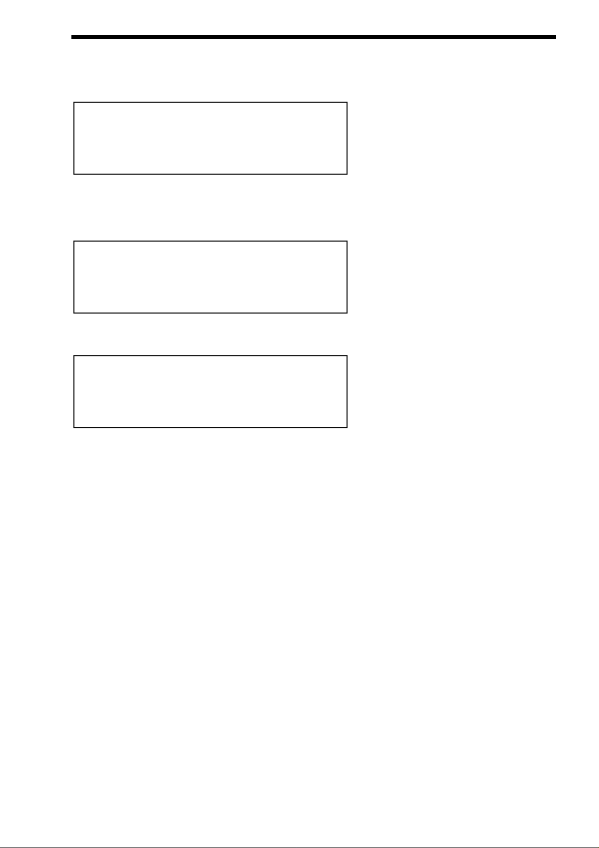
There are a lot of sounds in Supernova II keyboard. These are arranged into “Banks”. There are 4 Banks of 128 Performances (
512 Performances in total ), 8 Banks of 128 Programs ( 1024 Programs in total ), 8 Drum Maps each with 50 Programs and a single Bank of 128 Favourites. Pressing the Program button will activate the Program Mode. The display will show:
The lit Program button indicates Program Mode has been selected. The bottom line of the display is indicating “Prog” followed by
the Bank and number of the Program. The top line displays the name of the Program.
Press the Bank Up button. The display changes to:
Program Bank B has now been selected. A further 2 digit entry is required to determine the location of the sound within this Bank if
different from the current selection. Press ‘120’ then ‘3’ on the keypad. The display shows:
And the selected Program has changed.
Pressing the Bank Down button once will bring Supernova II keyboard back to the A Bank.
Selecting Performances or Favourites is done in exactly the same way.
When sounds are selected from the front panel, the appropriate MIDI Bank and Program change messages are sent on the last
entry of the keypad. These can be recorded on Computer Software / Sequencer. Selecting sounds via MIDI is very simple, just
send the appropriate MIDI Bank number and Program change commands to Supernova II keyboard from the Computer Software /
Sequencer. To change Programs and Performances, these messages should be sent on the Global MIDI Channel. If however you
have a Multitimbral Performance, individual parts can be changed with suitable Bank number and Program change messages on
the individual MIDI Channels assigned to the “Parts” of the Performance.
There is a chart on page 166 outlining all the different Bank numbers for selecting the different modes via MIDI.
Snotty Nose
Prog B123
Z-Plane VeloPick
Prog BOOO
Uni*Syn
Prog AOOO
SELECTING PROGRAMS, PERFORMANCES & FAVOURITES
33
Page 34
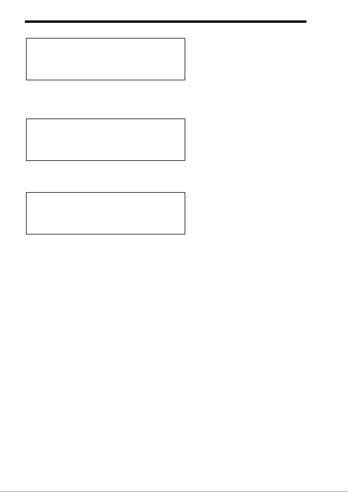
SELECTING DRUM MAPS AND DRUM MAP PROGRAMS
Pressing the Program button will activate the Program Mode. The display will show:
The lit Program button indicates that Program Mode has been selected. The bottom line of the display is indicating “Prog” followed
by the Bank and number of the Program. The top line is displaying the name of the Program.
Press the Bank Up button 8 times. The display changes to:
Drum Map a000 has now been selected. A further 2 digit entry is required to determine the location of the sound within this Drum
Map if different from the current selection. Press the higher ‘0’ button followed by the lower ‘2’ button on the keypad. The display
shows:
And the sound has changed showing Drum Program a002. Alternatively as all the 50 programs in Drum Bank a are simultaneously
available on the keyboard, the selection can be made from the keyboard. Play the keyboard until the sound desired is found. Now
play the note while holding down the Page Down button. If D1 is played the display should look the same as above.
When sounds are selected from the front panel, the appropriate MIDI Bank and Program change messages are sent on the last
entry of the keypad and can be recorded on Computer Software / Sequencer. Selecting sounds via MIDI is very simple, just send
the appropriate MIDI Bank number and Program change commands to Supernova II keyboard from the Computer Software /
Sequencer. To change Programs and Performances, these messages should be sent on the Global MIDI Channel. If however you
have a Multitimbral Performance, individual parts can be changed with suitable Bank number and Program change messages on
the individual MIDI Channels assigned to the appropriate “Parts” of the Performance.
There is a Chart on page 166 outlining all the different Bank numbers for selecting the different modes via MIDI.
808 Snare 2
Drum aOO2
909 Kick 2
Drum aOOO
Uni*Syn
Prog AOOO
34
Page 35
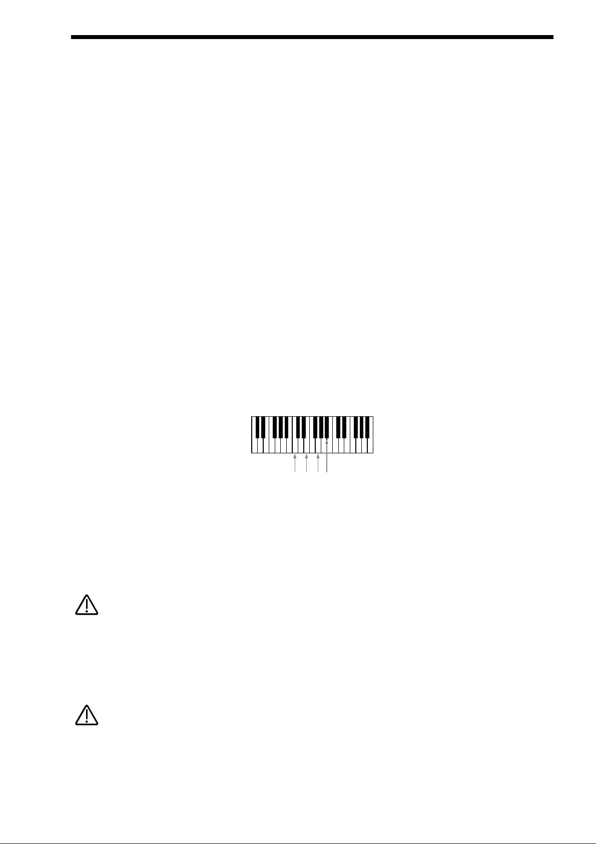
Editing and writing Arpeggio patterns is a bit like “Step” sequencing. It is not immediate and requires understanding of all the parameters necessary to create an Arpeggio pattern which performs how you want. To fully understand this guide it is necessary to
have a good understanding of all the standard Arpeggiator’s parameters.
The first thing to do is select a Program you want to use with an Arpeggiation. Use the Program, Bank and Keypad to make your
selection. Next, turn on the Arpeggiator if not already on with the Arp On/Off button. Assign a “User” pattern to the arpeggiator with
the “Pattern Bank” Parameter in page 1 of the Arpeggiator Menu button pages. You now have to decide what type of Pattern you
wish to create.
There are two basic types of Arpeggio patterns available. These are Monophonic, i.e. a chord is played on the keyboard and single
notes are played from that chord sequentially at a speed determined by the “Speed” knob. Polyphonic arpeggiation is also available, i.e. a chord is played on the master keyboard and all the notes are played simultaneously, but may be transposed, at a speed
determined by the “Speed” knob. To make a Monophonic pattern, select a “User” pattern in page 1 of the Arpeggiator Menu button
pages. Select a pattern between 000 and 063 (these are the Monophonic ones). Make a note of the pattern number you have
selected. For reasons that become clear below, we suggest that for the purposes of learning initially set the “Sync” parameter to a
low value (i.e. 8ths) and the “Fill In” parameter to “Off”. Both of these parameters are on page 4 of the Arpeggiator Menu pages.
Enter the Global Menu by pressing the Global Button. Go to page 7 and switch the Memory Protect parameter to Off. On page 18
select the same pattern you assigned to the Arpeggiator in the Program. You are now ready to start creating a Pattern. The procedures for editing Monophonic and Polyphonic patterns are slightly different.
Monophonic Patterns
A Monophonic pattern can be 1 step long (although there would not be much point in this except for recreating effects like LFO triggered basslines) or up to 64 steps long. Bear in mind that this can be also thought of as the “Resolution” of the pattern as the pattern can be “Synchronised” at differing time signatures. i.e. a 16 Step pattern synchronised at 16ths would be the same time duration as a 32 step pattern synchronised at 32nds. Decide on the number of steps you want to use and set the “No of Steps” parameter on page 18 of the Global Menu to suit. We suggest that for the purposes of learning, initially set this to a low value. i.e. 8,
this will mean that The Arpeggiator is synchronised to 8ths and the Number of steps you have assigned to the Pattern is 8. So this
is a 1 bar pattern.
In a Monophonic pattern, you decide which “Order” the individual “notes” within the “chord” you play are played. Imagine you are
playing the notes shown below:
There are 4 notes being played C, E, G & A# creating a C 7 Chord. The Supernova II keyboard scans the keyboard and “labels”
each of the played notes with a note number, starting with the lowest (if the “Note ordering” parameter is set to “Up”) . In this case
C = 1, E = 2, G = 3 & A# = 4. If a D was played instead of the E the numbering would be as follows C = 1, D = 2, G = 3 & A# = 4.
If a D was played instead of the C the numbering would be as follows D = 1, E = 2, G = 3 & A# = 4. It is important to understand
this relationship to understand the next step.
As you remember, there are 8 steps allocated in the assigned pattern. You can edit each step individually by selecting the step you
wish to edit with the “Step” parameter on Page 18 of the Global Menu, similarly altering the “Note” number assigned to that step on
the same page with the “Note” parameter.
A “Gate” of “Norm” or “Glide” must be assigned to the currently selected step on this page for the “Note” parameter on this page to
become available.
For example to create a simple Up/Down pattern program the following:
Step 1 = Note 1, Step 2 = Note 2, Step 3 = Note 3, Step 4 = Note 4, Step 5 = Note 4, Step 6 = Note 3, Step 7 = Note 2, Step 8 =
Note 1. The sequence of notes played is 1,2,3,4,4,3,2,1 etc. etc.
If more or less notes are played than you have programmed, the pattern will not play as expected. In the above example, if 6 notes
were played, the 5th and 6th notes played would never sound because the pattern data does not reference notes 5 or 6. In the
above example, if 2 notes were played the following would occur:
Step 1 = Note 1, Step 2 = Note 2, Step 3 = Note 2, Step 4 = Note 2, Step 5 = Note 2, Step 6 = Note 2, Step 7 = Note 2, Step 8 =
Note 1.
EDITING & WRITING ARPEGGIATOR PATTERNS
35
C
(1)E(2)G(3)A#(4)
NOTE:
NOTE:
NOTE:
NOTE:
Page 36
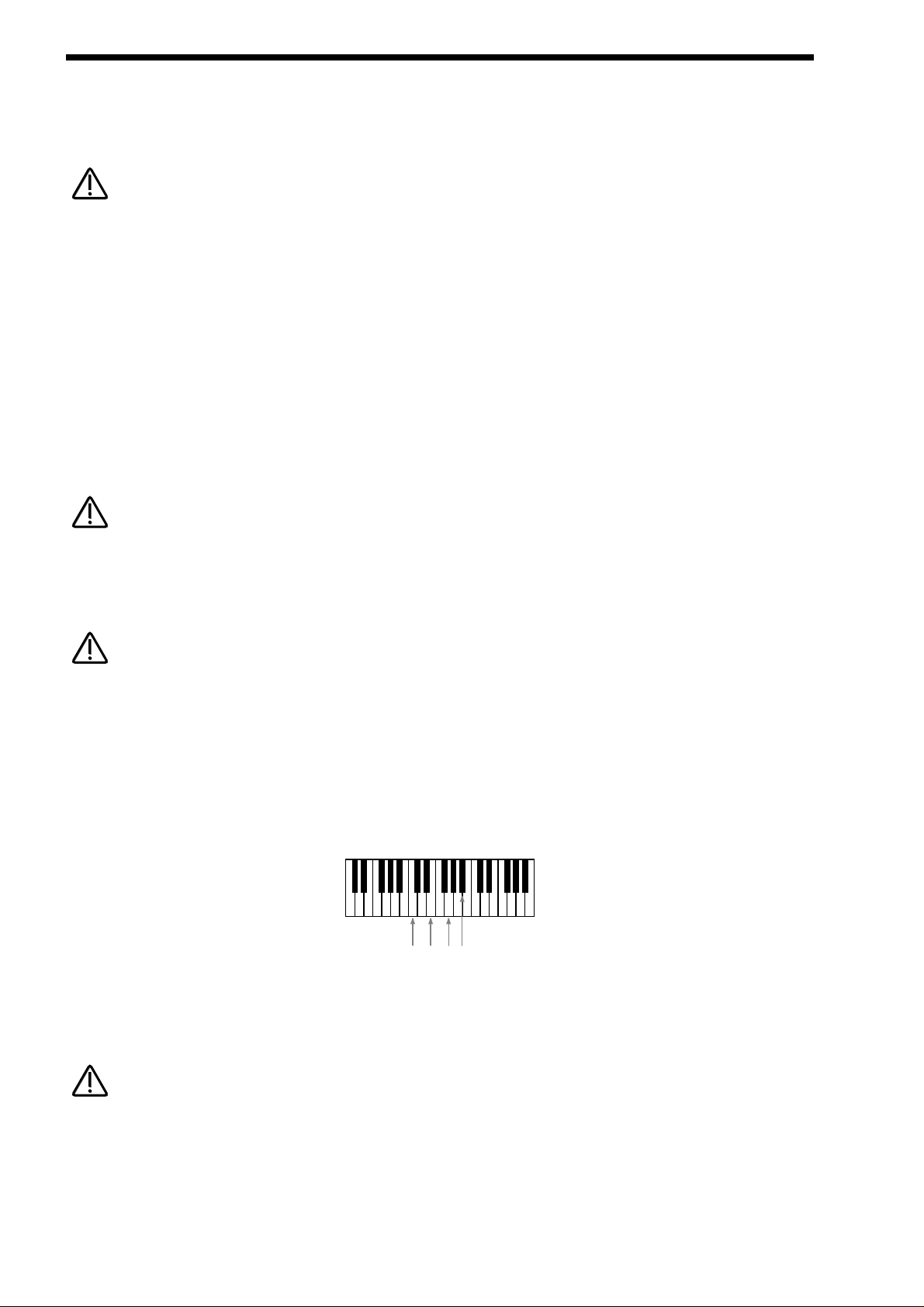
EDITING & WRITING ARPEGGIATOR PATTERNS
The sequence of notes played is 1,2,2,2,2,2,2,1 etc. etc. This is why the “Fill In” parameter is there. It should be currently in the
“Off” setting. In this setting you can program your patterns more efficiently, but for the best results when played, it should be set
to”On”. In this position, the keyboard notes normally missed out by Arpeggiator are intelligently inserted so that larger or less numbers of notes than are programmed into the pattern can be used.
In Monophonic patterns, there is a limit of 12 different note values which can be programmed into a pattern.
Of course much more interesting sequences are possible. i.e.
Step 1 = Note 4, Step 2 = Note 1, Step 3 = Note 3, Step 4 = Note 2, Step 5 = Note 3, Step 6 = Note 2, Step 7 = Note 1, Step 8 =
Note 4.
This produces the sequence of notes 4, 1, 3, 2, 3, 2, 1, 4 etc. etc- a kind of inside-out Up/Down sequence of notes. When you con-
sider that there are up to 64 steps available, it can be seen that there are many interesting things possible. There are 2 other parameters associated with programming Monophonic patterns. On page 19 of the Global Menu, you can also assign a note velocity
value for each of the pattern steps. On the same page, Gate type can also be assigned for each step of the pattern. When the
“Gate” parameter is set to “Normal” the setting of the “Gate” knob applies. When the “Gate” parameter is set to “Tie” the note is
“Tied” to the note in the previous pattern step. This allows syncopated rhythms to be created and can be used to great effect if the
pattern is set to have many steps. When the “Gate” parameter is set to “Rest”, no note is played on the selected step. Finally,
when the “Gate” parameter is set to “Glide”, the Portamento is engaged when the selected step switches to the next step. Then the
Portamento is switched off. This is great for creating those TB303 type patterns with slides.
Glide will only work when the polyphony of the Program / Part is set to Mono.
Arpeggiator Pattern data can be also entered in via the keyboard. Note and Velocitysettings for each step can be easily entered
using the keyboard. Using a sustain pedal also allows gate characteristics to be entered. Refer to the “Arp pattern editing via kbd”
Parameter on page 17 of the Global Menu for details.
The Constant pitch parameter does not apply to Monophonic patterns. For these, it will do nothing if set to On or Off.
Polyphonic patterns
To create a Polyphonic pattern, select a “User” pattern on page 1 of the Arpeggiator Menu pages. Select a pattern between 064
and 127 (these are the Polyphonic ones). Make a note of the pattern number you have selected. Polyphonic patterns differ in the
sense that all the notes played on the keyboard sound at once. Initially this can be thought of as a kind of “Gater”. Instead of
assigning which “Note” out of the ones you are playing will be played at each step in the pattern, in a Polyphonic pattern, all the
notes may be transposed at each step by a definable amount. The ‘Note’ value when edfining each pattern step therefore refers to
the amount of transposition applied to all playing notes. Here is an example. The keyboard notes being played are shown below:
This is a C7 chord. Below is an example Polyphonic Pattern, again of 8 steps in length:
Step 1 = Note 0, Step 2 = Note 2, Step 3 = Note -2, Step 4 = Note 0, Step 5 = Note 0, Step 6 = Note 12, Step 7 = Note -12, Step 8 =
Note 0.
This results in a chord sequence of C7, D7, A#7, C7,C7, C7 ( one octave up ), C7 ( one octave below ), C7. etc. etc.
In Polyphonic patterns there is a limit of -36 to +36 semitones range that can be programmed into a pattern.
Negative as well as positive values can be entered into the “Note” parameter in Polyphonic patterns. Again, when you consider that
there are up to 64 steps available in a pattern, it will be realised there are many things possible. Like the Monophonic patterns,
there are 2 other parameters for each pattern step associated with programming Polyphonic patterns. They perform the same functions in Polyphonic patterns as for Monophonic patterns. On page 19 of the Global Menu you can assign velocity values for each of
the steps. On the same page, the Gate time can be assigned for each step of the pattern.
36
NOTE:
NOTE:
NOTE:
NOTE:
NOTE:
NOTE:
C
(1)E(2)G(3)A#(4)
NOTE:
NOTE:
Page 37

When the “Gate” parameter is set to “Normal”, the setting of the “Gate” knob applies. When the “Gate” parameter is set to “Tie”,
the note is “Tied” to the note in the previous pattern step. This allows syncopated rhythms to be created and can be used to great
effect if the pattern is set to have many steps. When the “Gate” parameter is set to “Rest”, no note is played on the selected step.
When the “Gate” parameter is set to “Glide”, the Portamento is engaged. When the selected step switches to the next step, the
Portamento is switched off. This is great for creating those TB303 type patterns with slides.
The “Fill In” parameter does not apply for Polyphonic patterns and does nothing if switched “On” or “Off”.
Glide will only work when the polyphony of the Program / Part is set to Mono.
Several Monophonic and Polyphonic patterns can be used at once in a Performance. For example, one doing a Bass type Pattern,
one doing a TB303 thing, one doing a “Classic” Up/Down thing etc. etc. It is even possible to have the Arpeggiators in the different
programs synchronised to different time signatures. When doing this, turning the “Speed” knob will alter the speed of all the arpeggiators since although they may be running at different time signatures, they will still all reference the same MIDI clock. In other
words, it is not possible to have multiple arpeggiators running on different clock speeds. If you wish the arpeggiators to run at differing time signatures, set the “Sync” parameter in the Arpeggiator Menu to differing values.
EDITING & WRITING ARPEGGIATOR PATTERNS
37
NOTE:
NOTE:
NOTE:
NOTE:
Page 38
EDITING & WRITING PROGRAMS
Editing Programs is easy on the Supernova II keyboard as virtually all the controls needed to create a sound are found on the front
panel. First make sure that the Supernova II keyboard is in the Program mode. The Program button should be lit. Now it is just a
case of adjusting the knobs and buttons in the Oscillator, Filter, LFOs, Envelopes, Arpeggiator and Effects Sections until the
desired sound is created. Notice that the display changes to display the name of the rotary control you are currently editing. The
display will remain displaying this parameter after you stopped adjusting the rotary control ( unless currently within a “Menu” ). The
display shows the first rotary control to be adjusted, of course many rotary controls can be adjusted at once, but in this case the
display only shows the last control to be moved.
Writing Programs is a destructive operation. It is strongly advised to make back-ups of your data occasionally to a Computer,
Sequencer or Data filing device. Factory sounds in Program banks A,B,C & D can be recalled from the Supernova II Keyboard’s
on-board ROM. See page 52 for details on how to do this.
Once a sound has been created, it may be stored in any of the 8 banks of 128 Programs. To do so press the Write button. The display shows:
The top line of the display shows the current Program location on the left and the Program’s destination on the right. The bottom
line displays the Program’s name, in this case Uni*Syn.
While in this saving mode, it is possible to change the destination of the new sound using the bank and keypad buttons or the
upper Data knob. For example, when pressing the Bank button in the above example, the display will show:
Bank B has now been selected as the destination. A further 2 digit entry is required to determine the location of the sound within
this Bank if different from the current selection. Press ‘120’ and ‘3’ on the keypad. The display shows:
The destination of the sound to be written is now B Bank number 123.
While in this mode, the Compare button has a different function to its normal operation. The Compare button in this mode toggles
between the currently edited sound and the destination Program. The “Program” button will flash when this function is active.
Once the destination for the Program has been decided, press the Write button again. The display shows:
The name of the Program can be altered when in this mode. In the display the first character of the Program’s name has a cursor
under it. Using the higher Data knob you can scroll through the character set for that character. Using the lower Data knob you can
move the cursor horizontally to a different character position in the name.
Name Prog B123
‘Uni*Syn ’
Write Prog AOOO to B123?
Snotty Nose
Write Prog AOOO to BOOO?
Z-Plane VeloPick
Write Prog AOOO to AOOO?
Uni*Syn
38
NOTE:
NOTE:
NOTE:
NOTE:
Page 39

Pressing the Page Up button while in this mode inserts a space at the cursor position. Pressing Page Down while in this mode
deletes the character at the cursor. The Keypadand Bank buttons also provide useful shortcuts when in this mode. Pressing the
Keypad buttons with or without the 2 bank buttons perform several functions. These are as follows.
Top Row
a b c d e f g h I j k l m
Top Row + Bank Up button (momentary action)
n o p q r s t u v w x y z
Top Row + Bank Down button (latched action)
A B C D E F G H I J K L M
Top Row + Bank Up & Down buttons together
N O P Q R S T U V W X Y Z
Bottom Row
0 1 2 3 4 5 6 7 8 9
Bottom Row + Bank Up button (momentary action)
Space . - # ( ) [ ] ! *
Bottom Row + Bank Down button (latched action)
[Current word 1st] [Current word Last] [Previous word 1st] [Next word 1st] [Previous word last]
[Next word last] [Previous space] [Next space] [1st char] [Last char]
Bottom Row + Bank Up & Down buttons together
[Toggle case char] [Char upper case] [Char lower case] [All words lower case with Upper case first letter] [All words upper case]
[All words lower case] [Rotate text left] [ Rotate text right] [Clear text] [Restore text]
Once the name has been selected, press Write again. The display shows:
The Supernova II keyboard is asking for confirmation that you wish to write over the destination Program, replacing it with the
newly edited sound. On the top line of the display, it can be seen that there is the category parameter. This is where you set the
category of the Program so that the “Finder” mode can locate programs with the same category assigned. To adjust this parameter,
use the higher Data knob. There are 20 different categories. Refer to page 47 for details on the categories.
To complete the operation, press the Write button to confirm. The display shows:
This will stay on the screen for several seconds then revert back to the standard Program Mode display.
Uni*Syn
Prog B123
Prog B123
Saved!
Category - Hard Lead
Write to store
EDITING & WRITING PROGRAMS
39
NOTE:
NOTE:
Page 40

EDITING & WRITING PROGRAMS
At any stage during the write procedure, pressing the Program button will exit the write procedure (the Program will not be saved)
and return the Display to showing the Program name and location.
The current selection of various buttons such as Oscillator, LFO, ENV2 or 3 plus the selection of Mod Sources & Destinations in
the Oscillator and Filter sections are memorised when a Program is written into memory. This allows any setup to be recalled when
the program is recalled. This can be very useful in live performance situations.
Editing Drum Map Programs is almost the same as editing normal Programs. There is one extra Drum Map parameter that only
applies when the Program is placed within a Drum Map, defining the pitch the Program will play at when it is in a Drum Map. To do
this, select Program mode ( Program button is lit ) and access the desired Drum Map with the bank buttons. For example, if Drum
Map ‘a’ was selected, the display should show:
While in this mode, press the Tune button in the Part edit section. The display will show:
The parameter is “Drum played as”, in this case with a value of E3.
This parameter determines the note the Drum Program will be pitched at. This is not the note on the keyboard that the Drum
Program is triggered from (that is determined by the location within the Drum Map and is not re-assignable), but it is the pitch of
the Program when sounded. This can be set with the higher Data knob or directly by using the keyboard. To do this, simply play
the desired note on the keyboard while holding down the Page Up button while this display is showing. The appropriate note value
will automatically be inserted for the currently selected Program. The range of this parameter is C-2 to G8. This parameter is memorised with a Program, even if the Program is not currently located within a Drum Map.
Writing of Drum Map Programs into memory is done in exactly the same way as Programs. Normal Programs can be freely written
into Drum Map Program locations and vice versa.
This parameter only takes effect when the Program is situated within a Drum Map.
Drum played as E3
909 Kick 2
Drum aOOO
40
NOTE:
NOTE:
NOTE:
NOTE:
NOTE:
NOTE:
Page 41

Editing Performances is very easy. After Pressing the Performancebutton the button lights and the Display shows:
Performances are made up of up to 8 Parts. The next thing to do is select the “Part” of the Performance you wish to edit. To do this
press the appropriate Part button in the Part edit section. In the above example, pressing Part 1 button the display will show:
The display is showing the Program currently assigned to the selected Part. Although this display is identical to the one used in
Program Mode, it is important to realise we are still in Performance Mode. The Performance button remains lit to confirm this. Any
Program from any one of the Program Banks or any Drum Map can be assigned to any Part of a Performance. You can use the
Bank button and the keypad buttons to alter the Program assigned to this Performance Part.
When in this mode, pressing the Tune, Velocity, Output, MIDI, Polyphony and Range Menu buttons will display the relative parameters for the currently selected Part. If any of the Tune, Velocity, Output, MIDI, Polyphony and Range buttons are pressed, it will
flash indicating that the appropriate Menu has been selected. This allows easy comparison of values in different Parts. For example, press the MIDI button after Part 1 of a Performance has been selected. The display will show:
The MIDI button is flashing indicating the MIDI Menu is selected. Pressing another Part button will light the selected Part button
and the display will show the MIDI parameters for the newly selected Part as shown below.
To exit any of the Tune, Velocity, Output, MIDI, Polyphony or Range Menus, simply press the Performance button again. The display will change back to showing the currently selected Performance as shown below:
Alternatively, pressing the flashing Menu button will return the display to the Performance (If no part button had been selected ) or
the display will show the Program assigned to the currently selected part ( If a Part button had been selected ).
For details on the parameters in the “Tune”, “Velocity”, “Output”, “MIDI”, “Polyphony”, and “Range” menus, refer to the “Part Edit
Section” of this manual, starting on page 134.
Blaster Master
Perf AOOO
Sustain Disable
MIDI channel 8
Sustain Enable
MIDI channel Global
DigiTrowserCough
Prog EO3O
Blaster Master
Perf AOOO
EDITING & WRITING PERFORMANCES
41
Page 42

EDITING & WRITING PERFORMANCES
Pressing any of the Part buttons when in Performance Mode not only makes the display show the Part’s Program name and location but also brings the selected Part up on the front panel controls. This allows editing of Programs while in Performance Mode.
All the edits made are transmitted as Controllers or NRPNs using the MIDI channel assigned to the Part of the Performance, so in
a Multitimbral Performance, each Part can be individually edited, recorded on a sequencer and played back into the Supernova II
keyboard.
At any stage during editing a Performance, pressing the Performance button will exit the “Part” display. The Display will revert to
showing the Performance name and location.
It is possible to temporarily “Mute” Parts of a performance allowing the easy auditioning of separate parts of a Performance whilst
editing or even during live performance situations. This is done by simply pressing the Mute button (the Mute button will light indication that the Mute mode is active ) and pressing the Part button that you want muted. The muted Part button will flash indicating
that it is muted. The display will change to:
The part is Muted. Pressing the Part button again while the Mute mode is active will un-mute the Part. The Part’s button will stop
flashing and remain lit. The display will change to:
The part is now re-activated. The display remains like this for a few moments and then reverts to:
The muting status of each part in a Performance is memorised with a Performance when it is saved to memory. This is handy for
live applications as a complete setup is stored complete with mutes. For example, 7 Parts of a Performance can be memorised
with Mutes on, leaving 1 Part active which is playing say a Bassline. Simply pressing the mute button and un-muting/muting Parts
while the sequencer is playing makes it easy to realise Breakdowns and Builds on the fly during a live performance.
Similarly there is a Solo function for auditioning sounds. This is done by simply pressing the Solo button ( the Solo button will light
indicating that the Solo mode is active ) and pressing the Part button that you want soloed. The Soloed Part’s button will light indicating that it is soloed and all the other part buttons will flash indicting that they are muted. The display will temporarily change to:
The part isSoloed. Pressing any other part button will similarly Solo that Part. Only one part can be soloed at one time.
To cancel the Solo mode, simply press the Solo button again. It is now unlit.
DigiTrowserCough
Part soloed
DigiTrowserCough
Prog EO3O
DigiTrowserCough
Part un-muted
DigiTrowserCough
(Muted) Prog EO3O
42
NOTE:
NOTE:
NOTE:
NOTE:
Page 43

To assign no Program to a Part ( Off ) set the Polyphony Parameter in the Polyphony button menu to “Off”.
Only one Performance can be used at any one time. Performances cannot be used as Parts of other Performances. You cannot
assign different Performances to different MIDI channels and expect to get Multiple Performances.
When Performance mode is entered, whatever Part happened to be selected when the Performance was saved is now selected.
To adjust the Program assigned to any Part (for example Part 1), press Part 1 button even if it is already lit. It will stay lit and the
display will change from showing the Performance Bank, Number and Name to displaying the Part’s Program with its Number and
name. To return to the display to the Performance Bank, Number and Name, press the Performance button.
Writing Performances is a destructive operation. It is strongly advised to make back-ups of your data occasionally to a Computer,
Sequencer or Data filing device. Factory sounds in Performance banks A and B can be recalled from ROM see page 52 for details
Once a Performance has been created, you can store the Performance in any one of the 512 Performance memories. To do so,
press the Write button. The display shows:
The top line of the display shows the current Performance location on the left and the Performance’s destination location on the
right. The bottom line displays the destination Performance’s name, in this case Blaster Master!
While in this mode, it is possible to change the destination Performance memory by using the Bank and Keypad buttons. For
example, when selecting 001 on the keypad in the above example, the display will show:
The destination of the Performance to be written is now A001.
While in this mode, the Compare button has a different function to its normal operation. The Compare button in this mode toggles
between the currently edited Performance and the destination Performance. The “Performance” button will flash when this function
is active.
Write Perf AOOO to AOO1?
Pad on Spec
Write Perf AOOO to AOOO?
Blaster Master
EDITING & WRITING PERFORMANCES
43
NOTE:
NOTE:
NOTE:
NOTE:
NOTE:
NOTE:
NOTE:
NOTE:
NOTE:
NOTE:
Page 44
EDITING & WRITING PERFORMANCES
Once the destination for the Performance has been decided, press the Write button again. The display shows:
The name of the Performance can be altered when in this mode. In the display, the first character of the Performances name has
a cursor under it. Using the higher Data knob you can scroll through the character set for that character. Using the lower Data knob
you can move the cursor horizontally to a different character position within the name.
Pressing the Page Up button while in this mode inserts a space at the cursor position. Pressing Page Down while in this mode
deletes the character at the cursor. The Keypad and Bank buttons also provide useful shortcuts when in this mode. Pressing the
Keypad buttons with or without the 2 bank buttons perform several functions. These are as follows.
Top Row
a b c d e f g h I j k l m
Top Row + Bank Up button (momentary action)
n o p q r s t u v w x y z
Top Row + Bank Down button (latched action)
A B C D E F G H I J K L M
Top Row + Bank Up & Down buttons together
N O P Q R S T U V W X Y Z
Bottom Row
0 1 2 3 4 5 6 7 8 9
Bottom Row + Bank Up button (momentary action)
Space . - # ( ) [ ] ! *
Bottom Row + Bank Down button (latched action)
[Current word 1st] [Current word Last] [Previous word 1st] [Next word 1st] [Previous word last]
[Next word last] [Previous space] [Next space] [1st char] [Last char]
Bottom Row + Bank Up & Down buttons together
[Toggle case char] [Char upper case] [Char lower case] [All words lower case with Upper case first letter] [All words upper case]
[All words lower case] [Rotate text left] [ Rotate text right] [Clear text] [Restore text]
Once the name has been selected, press write again. The display shows:
The Supernova II keyboard is asking confirmation that you wish to write over the destination Performance, replacing it with the
newly edited Performance. On the top line of the display, the Supernova II keyboard is asking if you wish to update( re-write ) all
the Programs used in the currently selected Performance. If this parameter is set to “No” then the only the Performance-specific
data is written into memory. Any changes made to the Program parameters will be lost.
If this parameter is set to “Yes” then any alterations made to the Programs ( excluding the over-rides such as Part Volume, Arp
On/Off and Effects settings (if the Parts Effects used parameter in the Output menu is set to Part) will be written into all the
Programs used in the selected Performance. The revised Program data will-overwrite the original Program memories.
Update progs ? No
Write to continue
Name Perf AOO1
‘Blaster Master ‘
44
NOTE:
NOTE:
Page 45
If this parameter is set to “Each”, then any alterations made to the Programs ( excluding the over-rides such as Part Volume, Arp
On/Off and Effects settings (if the Part Effectparameter is set to Part i.e. lit ) can be selectively saved one by one. This option is
ideal if Program data has been altered, but you wish to re-save the new versions in a different Program memory, avoiding overwriting the original version.
The Supernova II keyboard checks each Part’s Program in turn, comparing it to the original version. If any differences are found,
the Supernova II Keyboard asks for confirmation to save each Part individually, showing the Part number and the Program number.
Individual Parts can be left unsaved ( Skipped ) at this stage by turning the lower Data knob while in this mode.
When in this mode, the Compare button toggles between the destination Program and the edited Program. Both the Performance
and the Program buttons will flash when this Compare mode is active.
To complete the operation press the Write button to confirm. The display shows:
This will stay on the screen for several seconds then revert back to the standard Performance page.
At any stage during the write procedure, pressing the Performance button will exit the write procedure (The Performance and Part
Programs will not be saved) and return the standard Performance Mode Display to showing the Performance name and location.
Performance AOO1
Saved!
EDITING & WRITING PERFORMANCES
45
NOTE:
NOTE:
NOTE:
NOTE:
Page 46

MASTER VOLUME SECTION
Volume - Knob
This knob adjusts the overall output of the Supernova II keyboard on the Left and Right outputs.
This can be overridden by MIDI Controller Data. If a MIDI Controller 97 with a value of “0” has been received by the Supernova II
keyboard, no output will be heard regardless of the position of this knob. To reset the volume either transmit the relevant MIDI
Volumelevel or move the Volume knob. ( This automatically overrides the MIDI setting. )
The volumes of each “Part” in a Performance can be set individually using the Part select buttons and the Part Level knob in the
Part Edit Section.
Octave - Buttons
These buttons change the octave range played by the Keyboard. If both buttons are unlit, then the transposition is normal ( i.e. C1
to C6 ). Pressing the Octave > button transposes the Keyboard up one octave ( i.e. C2 to C7 ) and the button will light indicating
an upwards transposition has been made. The < Octave button works in a similar way but transposes down an octave. Successive
presses of these buttons produce more shifts in transposition at whole octave intervals. The maximum range of transposition possible is +/- 3 octaves.
If either of the octave buttons are lit, ( octave transposition up or down is active ) the normal transposition of C2 to C7 can be
recalled by pressing both the Octave buttons at the same time.
46
master volume
octave
NOTE:
NOTE:
NOTE:
NOTE:
NOTE:
NOTE:
Page 47

This is where you select the various operating modes of the Supernova II keyboard, initiate the Finder function, edit Global parameters, Compare and Write Performances or Programs, assign Programs or Performances to the Favourites map, select Program,
Performance or Favourites Mode and play the Factory Demo.
Find - Button
With so many sounds, it can be a little difficult to find your favourite sounds quickly. For this reason the Supernova II keyboard features a “Finder” mode that can find similar types of sounds. The Supernova II keyboard has 20 “Categories” of sounds. They are
as follows:
1 Bass 9 Pad 17 User 1
2 Hard Bass 10 Strings 18 User 2
3 Soft Lead 11 Keyboard 19 User 3
4 Hard Lead 12 SFX 20 User 4
5 Porta Lead 13 Drums
6 Arpeggio 14 Piano
7 Motion 15 Organ
8 Bell 16 Brass
Each Program in the Supernova II keyboard has a “Category” assigned to it. The Finder uses categories to find similar sounds. To
use the Finder, press the Find button ( a small sequence suitable for the selected sound category will play if the “Finder demos”
parameter on page 10 of the global mode is set to On ). When the Find button is pressed the display will shows the currently
selected Program, along with its category. For example :
The higher parameter is “Category”. In this case with a value of Pad. The category relevant to the currently selected Program is initially selected. This parameter determines which category of sound you wish to find. Use the upper Data knob to select a different
category. The range of this parameter is Bass, Hard Bass, Soft Lead, Hard Lead, Porta Lead, Arpeggio, Motion, Bell, Pad, Strings,
Keyboard, SFX, Drums, Pianos, Organ, Brass & User 1 to User 4.
The lower parameter shows the Program found in the selected category. In this case with a value of E080 Synced Formant 1.
Use the lower Data knob to find the previous or next Program in the same category.
To return to normal operation, press the Program or Performance button.
Global - Button
The Global Menu contains all the parameters that affect the “Global” operation of Supernova II keyboard. This menu is accessed
by pressing the Global button.
When any Global data is written into memory, the currently selected Program or Performance will become the “Power Up” sound.
i.e. the sound the Supernova II keyboard defaults to when switched on.
When this button is pressed, a series of pages is available on the display containing parameters relevant to this section.
In the Global Menu there are 19 pages available. These are selected using the Page Up & Page Down buttons to the left of the
display.
Category - Pad
EO8O Synced Formant 1
demo tracks
MODE SECTION
47
find global
compare assign
performanceprogram
write
favourites
favourites
NOTE:
NOTE:
Page 48

MODE SECTION
There are a maximum of 2 parameters displayed on any page. One for each line on the display. The upper and lower Data knobs
on the right of the display are used to alter these parameter’s values.
Page 1 looks like so:
The higher parameter is “Master tune”. In this case with a value of +00.
This parameter determines Global tuning of Supernova II keyboard. Use the upper Data knob to adjust this parameter. The range
of this parameter is -64 to +63 cents. This parameter is memorised with the Global settings.
To write any changes to this parameter into memory, press the “Write” button while in this mode. Also note the “Memory Protect”
has to be set to “Off” for this to be possible.
The lower parameter is “Global MIDI chan”. In this case with a value of 1.
This parameter determines the Global MIDI Channel for the Supernova II keyboard. This Channel is always used when in Program
Mode. This setting is also used for transmission and reception of Sysex data and for selecting Program Mode or Performance
Mode via MIDI. Use the lower Data knob to adjust this parameter. The range of this parameter is 1 to 16.
This parameter is memorised with the Global settings.
To write any changes to this parameter into memory press the “Write” button while in this mode. Also note the “Memory Protect”
has to be set to “Off” for this to be possible.
Page 2 looks like so:
The only parameter on this page is “Sysex transmission”, In this case with a value of Single Program.
This parameter selects the type of data to be dumped via MIDI System Exclusive. Use the lower Data knob to adjust this parameter. The range of this parameter is Single program, All programs, Single prog request, All progs request, Single performance, All
performances, Single perf request, All perfs request, Single arp pattern, All arp patterns, Single patt request, all patts request,
Global parameters, Globals request, Program bank A, Program bank B, Program bank C, Program bank D, Program bank E,
Program bank F, Program bank G, Program bank H, Program bank A request, Program bank B request, Program bank.C request,
Program bank D request, Program bank E request, Program bank F request, Program bank.G request, Program bank H request,
Performance bank A, Performance bank B, Performance bank C, Performance bank D, Performance bank A request,
Performance bank B request, Performance bank C request, Performance bank D request, Drum map a, Drum map b, Drum map c,
Drum map d, Drum map e, Drum map f, Drum map g, Drum map h, Drum map a request, Drum map b request, Drum map c
request, Drum map d request, Drum map e request, Drum map f request, Drum map g request, Drum map h request, Patt bank U,
Patt bank V, Patt bank W, Patt bank U request, Patt bank V request, Patt bank W request, Total data & Total data request. This
parameter is memorised with the Global settings.
Once the desired type of Sysex dump has been selected, the dump is initiated by pressing the MIDI button in the Part Edit section.
Sysex dumps can only be transmitted in this way while this Menu page is displayed.
When a Sysex dump is transmitted, the current Global MIDI channel setting is encoded into the dump. Normally, the Supernova II
Keyboard will only accept a Sysex dump which corresponds to its current Global MIDI channel setting. This is a safety feature in
case there is more than one Supernova II Keyboard present in the MIDI network. It is possible to send a Sysex dump which will
always be accepted by a Supernova regardless of its Global MIDI channel setting. This is done by holding down the Compare button before pressing the MIDI button to initiate the dump. This feature is useful if for example, you are preparing a sound library for
other people to load or the Global MIDI channel setting is not known for the destination Supernova II Keyboard.
Sysex transmission -
Single program
Master tune +OO
Global MIDI chan 1
48
NOTE:
NOTE:
NOTE:
NOTE:
NOTE:
NOTE:
Page 49
The Supernova II keyboard can accept System Exclusive dumps while in any mode.
To write any changes to this parameter into memory press the “Write” button while in this mode. Also note the “Memory Protect”
has to be set to “Off” for this to be possible.
Page 3 looks like so:
The only parameter on this page is “Sysex Reception”. In this case with a value of Normal (Rx as sent).
This parameter determines how incoming Sysex data will be received. if the incoming sysex message is a bank dump, it is possible
to over-ride which bank it will be written into. Use the lower Data knob to adjust this parameter. If this parameter is set to “Normal
(Rx as sent)”, system exclusive reception is enabled and any incoming bank dumps will be stored in the same location as they
were sent from. i.e. a Prog bank A dump will be written to Prog bank A. If this parameter is set to “All progs to bank A”, any incoming Program bank dump will be written into Program bank A regardless of its original location when transmitted. If this parameter is
set to “All perfs to bank A”, any incoming Performance bank dump will be written into Performance bank A regardless of its original
location. If this parameter is set to “Disabled” no sysex messages will be accepted. The range of this parameter is Disabled,
Normal (Rx as sent), All progs to bank A, All progs to bank B, All progs to bank C, All progs to bank D, All progs to bank E, All
progs to bank F, All progs to bank G, All progs to bank H, All progs to Dmap a, All progs to Dmap b, All progs to Dmap c, All progs
to Dmap d, All progs to Dmap e, All progs to Dmap f, All progs to Dmap g, All progs to Dmap h, All perfs to bank A, All perfs to
bank B, All perfs to bank C, All perfs to bank D, All patts to user (U), All patts to user (V) & All patts to user (W). This parameter is
memorised with the Global settings.
To write any changes to this parameter into memory press the “Write” button while in this mode. Also note the “Memory Protect”
has to be set to “Off” for this to be possible.
Page 4 looks like so:
The higher parameter is “MIDI clock”. In this case with a value of Int.
This parameter determines If the Supernova II keyboard is syncing to Internal Clock, External MIDI Clock or either. Use the upper
Data knob to adjust this parameter. When set to “Int”, internal clock will always be used and the tempo can be controlled by the
Arpeggiator Speed knob. When set to “Ext”, external MIDI clock will always be used. When set to “Auto”, internal clock will be used
unless an external MIDI clock is detected, at which point the External MIDI clock will then be used instead. The range of this parameter is Int, Ext & Auto. This parameter is memorised with the Global settings.
To write any changes to this parameter into memory press the “Write” button while in this mode. Also note the “Memory Protect”
has to be set to “Off” for this to be possible.
The lower parameter is “Pedal/breath”. In this case with a value of Off.
This parameter determines if the Supernova II keyboard re-maps incoming Pedal data and Breath Control MIDI data ( CC no 2 ). It
is possible to remap these messages into Mod wheel data ( CC no 1 ), Aftertouch data or any controller from 3 to 119, as well as
Pitchbend data . Use the lower Data knob to adjust this parameter. This allows incoming Pedal & Breath Control data to manipulate
most of Supernova II keyboard’s key parameters directly. The range of this parameter is Off, MW, A/T, CC3 to CC119, Bend,
Bend+, Bend-, NRPN75 to NRPN77, NRPN95 and NRPN96. This parameter is memorised with the Global settings.
MIDI clock Int
Pedal/breath Off
Sysex reception -
Normal (RX as sent)
MODE SECTION
49
NOTE:
NOTE:
NOTE:
NOTE:
NOTE:
NOTE:
NOTE:
NOTE:
Page 50
MODE SECTION
To write any changes to this parameter into memory press the “Write” button while in this mode. Also note the “Memory Protect”
has to be set to “Off” for this to be possible.
Page 5 looks like so:
The higher parameter is “Breath mode”. In this case with a value of Absolute.
This parameter determines how incoming Breath controller information is interpreted by the Supernova II keyboard. Use the higher
Data knob to adjust this parameter. If this is set to Absolute then the destination ( the parameter assigned with the “Pedal/breath”
parameter on Page 4 of Global Menu ) will be modulated directly regardless of its setting in the currently assigned program. If this
parameter is set to Mod+, then the breath control value would be added to the value of the destination in the currently loaded program. If this parameter is set to Mod-, then the breath control value would be subtracted from the value of the destination in the
currently loaded program. i.e. In Absolute mode, if the destination is Cut-off Frequency and the currently assigned program's Cutoff Frequency is 64, when a breath control message with a value of 1 is received the Cut-off Frequency would change to 1. If in
this case this parameter was set to Mod+ the value of the Cutoff Frequency would be 65. If in this case this parameter was set to
Mod-, the value of the Cutoff Frequency would be 63. The range of this parameter is Absolute, Mod+ and Mod-. This parameter is
memorised with the Global setting.
To write any changes to this parameter into memory press the “Write” button while in this mode. Also note the “Memory Protect”
has to be set to “Off” for this to be possible.
The lower parameter is “Breath sensing”. In this case with a value of Norm.
This parameter determines how sensitive the Supernova II keyboard is to incoming breath controller messages. Incoming Breath
control messages can be dealt with as they are when this parameter is set to normal. If this parameter is set to a negative number
(-3 for example), incoming breath control messages are scaled down. Alternatively, incoming breath control messages can be
exaggerated or amplified by setting this parameter to a positive number (+3 for example). Use the lower Data knob to adjust this
parameter. The range of this parameter is -5 to -1, Norm, +1 to +5. This parameter is memorised with the Global settings.
Page 6 looks like so:
The higher parameter is "Arp trans chan" (Arpeggiator real-time transpose channel), in this example with a value of Kbd. Use the
upper Data knob to adjust this parameter. This parameter is used to specify a MIDI channel which can be used to transposeall
Arpeggiators in real-time. When this parameter is set to Kbd, only the real-time transpose zone on the keyboard (active when the
Real Time Transpose button is lit) can be used for this purpose. When this parameter contains the value 1 to 16, note information
on an external MIDI channel can also be used for real-time transposition. The real-time transpose zone on the keyboard (active
when the Real Time Transpose button is lit) may still be used to transpose Arpeggiators, in which case the corresponding Note
information is transmitted via MIDI using the Arpeggiator real-time transpose channel specified by this parameter. The range of this
parameter is Kbd, 1 to 16. This parameter is memorised with the Global settings.
The amount of transposition applied to an Arpeggiator corresponds to the difference in semitones between the note played and the
note defined by the "Arp Transpose Reference Note" (also set on this Global Menu page – see below). The transposition can be
negative as well as positive. For example, if the "Arp Transpose Reference Note" is defined as note C3, playing C#3 will result in
the whole arpeggio being transposed up one semitone from its original key. If Bb3 is played, the whole arpeggio will now be transposed down two semitones from its original key and so on. To return the arpeggio to its original key (a transposition of zero semitones), it is necessary to play the same note value as defined by the "Arp Transpose Reference Note".
Arp trans chan Kbd
Arp trans ref C3
Breath mode Absolute
Breath sensing Norm
50
NOTE:
NOTE:
NOTE:
NOTE:
Page 51

The lower parameter is "Arp trans ref" (Arp transpose reference note), in this example with a value of C3. Use the lower Data knob
to adjust this parameter. This parameter determines the reference note as described above for the real-time Arpeggio transpose
function. The range of this parameter is C-2 to G8. This parameter is memorised with the Global settings.
An Arpeggiator must have its Real-time transpose parameter (set in the Arpeggiator Menu) set to On for real-time transposition to
take effect.
Whenever realtime transpose note data is received via MIDI or generated from the keyboard, the Transpose Zone button will blink
briefly.
To write any changes to this parameter into memory press the “Write” button while in this mode. Also note the “Memory Protect”
has to be set to “Off” for this to be possible.
Page 7 looks like so:
The higher parameter is “Local Control”. In this case with a value of On.
This parameter is normally set to On. With this setting, any knob movements or button presses on the front panel are transmitted
via MIDI and also control the synth engine directly. i.e. turning a knob will alter the sound produced regardless of any MIDI setup. If
this parameter is set to Off, knob movements and button presses on the front panel still transmit MIDI data but make no DIRECT
alteration to the sound. This is the best way to use the Supernova II keyboard with a sequencer as all the Channel re - mapping
features in sequencers can be taken advantage of fully. This parameter is memorised with the Global settings.
If there is no MIDI feedback loop connected at all (a sequencer with MIDI out of the Supernova II keyboard connected to MIDI in
on the sequencer and MIDI out of the sequencer connected to MIDI in on the Supernova II keyboard for example), when local control is set to off, the knobs and buttons on the front panel will appear to do nothing although changing parameter values may be
displayed on the display (this is to give an indication of the values in the MIDI data being transmitted).
When changing Programs, Performances or Favourites with the Local off and no MIDI loop present, the display will indicate any
change made on the keypad section but will not change the name of the sound. This is because the Supernova II keyboard is indicating that a change has been transmitted with the numbers but this message has not been received and therefore the sound and
its name has not changed.
If local control is set to off, When Parts are muted or soloed in Performance mode, flashing Part buttons will indicate the MIDI information transmitted, not necessarily relevant to each Part’s current mute status.
The lower parameter is “Memory protect”. In this case with a value of Off.
This parameter determines if the memory can be written to or not. Use the lower Data knob to adjust this parameter. In the “On”
position, Programs, Performances, Patterns or Global Data cannot be written into memory - a useful safety feature. In the “Off”
position, Programs, Performances, Patterns or Global Data can be written into memory. This parameter is memorised with the
Global settings.
Local control On
Memory protect Off
MODE SECTION
51
NOTE:
NOTE:
NOTE:
NOTE:
NOTE:
NOTE:
NOTE:
NOTE:
NOTE:
NOTE:
NOTE:
NOTE:
Page 52

MODE SECTION
Page 8 looks like so:
Pressing the Write button while this page is displayed starts the Restore procedure.
The single parameter on this page is “Restore from ROM:”. In this case with a value of One program.
This parameter allows the factory Programs, Performances, Global data and Arp Pattern data to be restored to the Factory
settings. Use the lower Data knob to adjust this parameter. Whatever selection is made with the lower Data knob is restored into
memory (ERASING WHATWAS THERE!!) when the “Write” button is pressed while in this mode. Additional pages appear depending on the selection. i.e. if “All data” is selected the Supernova II keyboard asks for confirmation which is set with the lower Data
knob. If you set this to “Yes” and press the “Write” button again to proceed, all the factory settings will be restored. If however “One
prog” was selected, the Supernova II keyboard asks which Program you want to restore. This is selected using the lower Data
knob and when pressing the “Write” button again, the Supernova II keyboard asks for the destination location (Program bank and
number) where the Program is to be stored. The range of this parameter is One prog, One perf, One patt, All progs, All perfs, All
patts, Globals, Favourites, All data, Prog bank A, Prog bank B, Prog bank C, Prog bank D, Perf bank A, Perf bank B, Dmap a,
Dmap b, Dmap c & Dmap d.
When All arp patterns is selected, pressing the Write button will bring up another page, this looks like so:
Here it is possible to restore the Factory User pattern Bank (Pattern Bank U) to any of the 3 User Pattern Banks. Use the lower
Data knob to select the destination Bank. The Range of this parameter is Arp pattern bank U, Arp pattern bank V & Arp pattern
bank W.
Only Program Banks A to D, Drum Maps a to d, Performance Banks A to B, Arp Pattern Bank U and the Global parameters can be
restored from ROM. The data for Program Banks E to H, Drum Maps e to h, Performance Banks C to D & Arp Pattern Banks V to
W are not held in the ROM and so cannot be restored. These are however available as .MID files free on the Novation website at
http://www.novationmusic.com
Page 9 looks like so:
The higher parameter is “Input/sw 1”. In this case with a value of Audio in.
This parameter determines the function of the Input/sw 1 input socket. Use the higher Data knob to adjust this parameter. In the
Audio in position the Input is configured to accept external audio signals. In the Switch position, the input is configured to work as a
Footswitch input for a Footswitch/Sustain pedal that is normally open. In the Switch-I position the input is configured to work as a
Footswitch input for a Footswitch/Sustain pedal that is normally closed. The range of this parameter is Audio in, Switch & Switch-I.
This parameter is memorised with the Global settings.
Input/sw 1 Audio in
Input/sw 2 Audio in
Write whole bank to
Arp pattern bank U
Restore from ROM:
One program
52
NOTE:
NOTE:
NOTE:
NOTE:
NOTE:
NOTE:
Page 53

The lower parameter is “Input/sw 2”. In this case with a value of Audio in.
This parameter determines the function of the Input/sw 2 input socket. Use the higher Data knob to adjust this parameter. In the
Audio in position the Input is configured to accept external audio signals. In the Switch position, the input is configured to work as a
Footswitch input for a Footswitch/Sustain pedal that is normally open. In the Switch-I position the input is configured to work as a
Footswitch input for a Footswitch/Sustain pedal that is normally closed. The range of this parameter is Audio in, Switch & Switch-I.
This parameter is memorised with the Global settings.
Page 10 looks like so:
The parameter is “Pedal/sw 3”. In this case with a value of Pedal-R.
This parameter determines the function of the Pedal/sw 3 input socket. Use the higher Data knob to adjust this parameter. In the
Pedal-R position, the input is configured to work as an Expression Pedal input (actually transmitting Breath Control CC2 messages) and so can mapped into any controller using the Pedal/breath parameter on page 4 of this menu. In this case, for an
Expression Pedal with the control output on the ring of the pedal jack. In the Pedal-T position, the input is configured to work as an
Expression Pedal input (actually transmitting Breath Control CC2 messages) and can mapped into any controller using the
Pedal/breath parameter on page 4 of this menu. In this case, for an Expression Pedal with the control output on the tip of the pedal
jack. i.e. a Korg EXP2 Expression Pedal. In the Switch position, the input is configured to work as a Footswitch input. In this case,
for a Footswitch/Sustain pedal that is normally open. In the Switch-I position the input is configured to work as a Footswitch input.
In this case, for a Footswitch/Sustain pedal that is normally closed. The range of this parameter is Pedal-R, Pedal-T, Switch &
Switch-I. This parameter is memorised with the Global settings.
The lower parameter is “Finder demos”. In this case with a value of Off.
This parameter determines if the “Finder” plays a category demo or not when activated. Use the lower Data knob to adjust this
parameter. In the On position, whenever the Finder mode is activated a small demo tune will play in the style of the category currently assigned to the selected program. In the Off position the finder function still works but no demo plays. This is useful when
working with an external sequencer and auditioning sounds while the sequencer is running. The range of this parameter is On &
Off. This parameter is memorised with the Global settings.
Page 11 looks like so:
The higher parameter is “Vel sensing”. In this case with a value of Hard.
This parameter alters the velocity curve of the Supernova II keyboard. Use the upper Data knob to adjust this parameter. This is
global and applies to all playing modes. In the Hard position, large Velocity changes are required to create a big change in
response. This is good for weighted and semi-weighted keyboard actions. In the Soft position, not so large Velocity changes are
required to create a big change in response. This is good for cheaper keyboard actions. The range of this parameter is Hard &
Soft. This parameter is memorised with the Global settings.
The lower parameter is “Knob mode”. In this case with a value of Pickup.
This parameter determines if the values of parameters altered by front panel Knobs jump immediately to the actual position of the
Knob as soon as it is turned or if the Knob has to pass “though” the value of the edited parameter before the knob starts editing the
parameter. Use the lower Data knob to adjust this parameter. In the Normal position, the value of the parameter being edited jumps
to the value of the Knob as soon as a knob is turned. This is good when creating sounds as the parameters are always “Live”. In
the Pickup position, no change to the parameter being edited will take place until the Knob is turned so that the it has passed
“through” the value of the edited parameter, thereby “picking it up”. The knob then becomes “live” and will start editing the parameter, transmiting the appropriate controller. The range of this parameter is Normal & Pickup.
Vel sensing Hard
Knob mode Pickup
Pedal/sw 3 Pedal-R
Finder demos Off
MODE SECTION
53
Page 54
When this parameter is set to “Pickup” mode no MIDI controller data will be sent and no edits to the parameter by Knob movements will occur until the Knob parameter has been picked up.
Page 12 looks like so:
The parameter is “Incoming control change”. In this case with a value of Enabled.
This parameter determines if the Supernova II keyboard responds to incoming MIDI controller messages or not. Use the lower
Data knob to adjust this parameter. This filter is global and applies to all playing modes. The range of this parameter is Enabled &
Disabled. This parameter is memorised with the Global settings.
The Incoming Control Change filter does not filter out Bank select messages (CC00 and CC32). These can be filtered using the
Incoming Program Change filter if required (see below).
Page 13 looks like so:
The parameter is “Incoming program change”. In this case with a value of Enabled.
This parameter determines if the Supernova II keyboard responds to incoming MIDI program change messages or not. Use the
lower Data knob to adjust this parameter. When this parameter is set to Enabled, any Program Change messages sent on Bank 0
will refer to the Program Map. This can be overridden by sending Bank & Program Change messages to a different Bank. Refer
page 147 for details on the Bank messages received by Supernova II keyboard. When this parameter is set to Favourites, any
Program Change messages will always refer to the Favourites map regardless of any Bank messages that have been received.
When this parameter is set to Disabled, all incoming bank and program change messages are ignored. This filter is global and
applies to all playing modes. The range of this parameter is Enabled, Favourites & Disabled. This parameter is memorised with the
Global settings.
If the Incoming Program Change filter is set to Disabled, it also filters out Bank select messages (CC00 and CC32).
Page 14 looks like so:
The higher parameter is “PCAVN”. In this case with a value of Program change.
These parameters determine if the Supernova II keyboard transmits various types of MIDI data. These are Program change,
Controllers, Aftertouch, Key Velocityor Arpeggiator keyboard note data. Use the upper Data knob to select the type of data to be
transmitted. The current selection is indicated on the top right of the display. On the bottom row of the display, an “.” or a “o” indicates if the current selected option is transmitted or not. Confirmation is displayed on the bottom right of the display as Yes or No.
PCAVN Program change
o
.... Tx ? Yes
Incoming program
change Enabled
Incoming control
change Enabled
54
MODE SECTION
NOTE:
NOTE:
NOTE:
NOTE:
NOTE:
NOTE:
Page 55
When the Program change selection is set to No, no Program change messages and Bank messages are transmitted. When the
Program change selection is set to Yes, Program change messages and Bank messages are transmitted when a new
Program/Performance/Favourite is selected.
When the Controller selection is set to No, no Controllers are transmitted. When the Controller selection is set to Yes, Controllers
are transmitted when knobs or buttons are edited.
When the Aftertouch selection is set to No, no Aftertouch messages are transmitted. When the Aftertouch selection is set to Yes,
Aftertouch messages are transmitted when pressure is applied to the keyboard.
When the Key Velocity selection is set to No, the Velocity of notes transmitted is fixed at 127. When the Key Velocity selection is
set to Yes, the Velocity of notes transmitted is determined by how hard the key are depressed.
When the Arpeggiator keyboard notes section is set to No, notes played on the keyboard which trigger arpeggios are never transmitted via MIDI. This can be used when recording the Arpeggiator’s output into a sequencer to make sure that only the
Arpeggiator's note output is recorded. This setting is global and affects all Programs. When set to Yes, notes played on the keyboard to trigger arpeggios are transmitted via MIDI provided that the Program/Part's MIDI channel does not conflict with the
Arpeggiator's 'Output' MIDI channel. If there is conflict, then keyboard notes are never transmitted anyway. In summary, when this
parameter is set to Yes and when Arpeggio notes to : parameter (in the Arpeggiator Menu) is set to Program only, keyboard notes
are always transmitted. When Arpeggio notes to : parameter is set to Program & MIDI or MIDI only, keyboard notes aretransmit-
ted provided the Output MIDI ch parameter is not set to Input (in which case there is always conflict) and the Output MIDI ch parameter is not the same MIDI channel as is being used to trigger the Program/Part.
The range of this parameter is Program change, Controllers, Aftertouch, Key Velocity or Arp kbd notes. This parameter is memorised with the Global settings.
This Key Velocity parameter only affects how the information is transmitted via MIDI. All internal sounds played by the keyboard will
always respond to the amount of velocity used to play the keyboard. This parameter does not affect the Arpeggiator's output if it is
transmitting notes via MIDI, though the keyboard notes actually used to trigger the Arpeggio will be transmitted (subject to the rules
above) with a maximum velocity setting of 127 if this parameter is set to "No".
The Controllers part of this parameter does not affect transmission of Bank select controllers when selecting new Programs /
Performances or the transmission of the Modulation Wheel.
Page 15 looks like so:
The higher parameter is “Sysex TX delay”. In this case with a value of 070ms.
This parameter determines the speed at which Data dumps made by the Supernova II keyboard are transmitted. Between each
discrete Sysex packet, the appropriate delay is inserted. Use the higher Data knob to adjust this parameter. This can be useful
when working with some PCs and MIDI interfaces which cannot receive the sysex data reliably ( i.e. Packet errors happen when
the dump is played back in. ). The range of this parameter is in Milliseconds and describes the pause between separate dumps in
a sysex stream. The range of this parameter is 050ms to 177ms. This parameter is memorised with the Global settings.
Sysex Tx delay O7Oms
Temp disp time 1OO
MODE SECTION
55
NOTE:
NOTE:
NOTE:
NOTE:
Page 56
This is not a definite “Fix it” for Packet errors. If the problem still persists try a different Computer/Sequencer package/MIDI
Interface. Packet errors are not a “Bug” in the Supernova II keyboard but a reliability problem with the device recording and playing
back the Sysex dump. This parameter simply tries to make it easier for equipment that does not work properly.
The lower parameter is “Temp display time”. In this case with a value of 100.
This parameter determines the amount of time that temporary displays remain on the display (for example if any menu is open. i.e.
flashing when any knob is adjusted, the display will change from the menu to the knob parameter until the adjustment of the knob
is stopped. Then after a short period the display reverts to the menu. This parameter determines that time). Use the lower Data
knob to adjust this parameter. The range of this parameter is 000 to 127. This parameter is memorised with the Global settings.
Page 16 looks like so:
The Supernova II keyboard features a “Favourites” mode that allows any incoming MIDI Program Change message or Keypad
selection to call up any Program or Performance from any Bank, or select a new Arpeggiator Pattern for the currently selected program. This Global Menu page provides an alternative way of assigning Favorites to the method described on page 29.
The Favourites are user programmable and can be memorised. To select the Favourite, simply press the Favourites button in the
Mode Section. See page 29 for details on the Favourites button. To select the Favourites mode via MIDI send a Bank Message of
0 (Controller 32 with a value of 0). When this Favourites Mode is selected, any incoming MIDI Program Changes or Keypad selections conform to the sequence in the Favourites memories. Assigning Programs, Performances and Arp patterns to Favourite locations can be done with the assign button in the Mode section. See page 30 for details on the Assign (favourites) button. On this
menu page, not only Programs & Performances can be assigned but also Arpeggiator Patterns and ‘Current Bank’ status.
Editing Favourites from within this menu provides a convenient way of inspecting/editing the Favourites without having to enter the
Favourites Mode.
The higher parameter is “Prog change”. In this case with a value of 002.
This parameter shows which Part of the Favourites Map will be displayed / Edited. Use the higher Data knob to adjust this parameter. The Favourites Map allows incoming MIDI Program Change Messages to call up any sound in the Supernova II keyboard. This
not only allows keyboards and sequencers that do not support MIDI Bank Select Messages access to any sound via MIDI but also
allows a user “Order” of sounds to be created which can be very useful in live performance. The range of this parameter is 000 to
127. This parameter is memorised with the Global settings.
The Program map can be made active at all times by setting the “Incoming program change” parameter on page 13 of the Global
mode to “Favourites”.
When a Program/Part receives a valid Bank Select Message (Controller 32) via MIDI IN, the bank will continue to remain selected
for the Program/Part until another Bank Select Message is received via MIDI IN.
This “Favourites Map” is assigned to MIDI Bank 0 (Controller 32 with a value of 0). If this message is received, the Supernova II
keyboard will switch from normal operation to Favourites Mode. Any Program changes received after that will be re-mapped
according to the “Favourites Map”. This can be disabled by sending another MIDI Bank Message calling up either one of the
Program or Performance Banks. See page 145 for details on the Bank Messages received by the Supernova II keyboard.
Program change OO2
Selects Perf AO1O
56
MODE SECTION
NOTE:
NOTE:
NOTE:
NOTE:
NOTE:
NOTE:
NOTE:
NOTE:
NOTE:
NOTE:
Page 57
To write any changes to the Favourites Map into memory, press the “Write” button while this page is displayed. Also note the
“Memory Protect” has to be set to “Off” for this to be possible.
The lower parameter is “Selects”. In this case with a value of Perf A010.
This parameter shows which selection is assigned to the selected Program Message set in the parameter above. Use the lower
Data knob and the Bank buttons to adjust this parameter. In this case, the sound assigned is Performance A010. Pressing the
Bank buttons while in this mode allows the selection of any Performance, Program, Drum Map or Arp Pattern Bank. Using the
lower Data knob allows any sound from the selected Bank to be set.The “Curr” setting is short for “Current” and when this setting is
used, incoming Program change messages will select a sound from the “Currently” selected bank. The range of this parameter is
Curr, Perf A, Perf B, Prog A, Prog B, Prog C, Prog D, Perf C, Perf D, Prog E, Prog F, Prog G, Prog H, Drum a, Drum b, Drum c,
Drum d, Drum e, Drum f, Drum g, Drum h, Arp M, Arp P, Arp U, Arp V & Arp W. This parameter is memorised with the Global settings.
Page 17 looks like so:
The parameter is “Arp pattern editing via kbd”. In this case with a value of Off.
This parameter determines if the Arpeggiator pattern data can be entered via the keyboard or not. When this parameter is set to
Off, no editing of Arpeggiator patterns via a keyboard is possible, only the step type editing on pages 20 of the Global Menu can be
used for this purpose. If this parameter is set to On, Notes and Velocity values for each pattern step can be entered directly from
the keyboard. To do this, set this parameter to On, then select a Pattern for editing. Select the number of steps in the pattern
required in page 18 of the Global Menu. Now go to page 19 of the Global Menu and check that the pattern is on step 1. On this
page, pressing a note on the keyboard will enter the note value and velocity value directly into the pattern. Releasing the keyboard
note will automatically advance the pattern to the next step. A sustain pedal on the keyboard can also be used when in this mode.
If no note is held down and the sustain pedal is pressed, a Rest is inserted at the current step. Releasing the sustain switch
advances the pattern to the next step. Similarly, pressing the pedal while no note is being played then, while still pressing the sustain switch, a note is played on the keyboard, inserts a tie at the current step. Releasing the Note on the keyboard then advances
the pattern to the next step. Pressing the pedal while a note is being played inserts a Glide to at the current step. Releasing the
Note on the keyboard then advances the pattern to the next step. The range of this parameter is Off, On, Note only, Vel only &
Gate only. This parameter is memorised with the Global settings.
Page 18 looks like so:
The higher parameter is “User Pattern”. In this case with a value of U000.
This parameter determines which of the User Patterns for the Arpeggiator is to be edited with the following pages. Use the upper
Data knob to select the Pattern number. Use the Bank buttons to select the Pattern Bank U, V or W. The range of this parameter is
U000 to U127, V000 to V127 & W000 to W127. This parameter is memorised with the Global settings.
User Patterns 000 to 63 are User Monophonic Patterns. User Patterns 64 to 127 are User Polyphonic Patterns.
To write any changes to the currently selected pattern into memory press the “Write” button while any of the pattern edit pages are
displayed. Also note the “Memory Protect” has to be set to “Off” for this to be possible.
User pattern UOOO
No of steps 32
Arp pattern editing
via kbd Off
MODE SECTION
57
NOTE:
NOTE:
NOTE:
NOTE:
NOTE:
NOTE:
Page 58
MODE SECTION
The lower parameter is “No of Steps”. In this case with a value of 32.
This parameter determines the number of steps in the chosen User Pattern. Use the lower Data knob to adjust this parameter. The
range of this parameter is 01 to 64. This parameter is memorised as Pattern data.
Page 19 looks like so:
The higher parameter is “Step Note Vel. Gate”. In this case with a value of Note.
This parameter determines the pattern parameter to be edited with the lower Data knob. Use the upper Data knob to select the
parameter to be edited. The cursor indicates the current selection, in this case N
ote.
When this parameter is set to “Step”, the value of the parameter below it determines the step to be edited. Use the lower Data
knob to adjust this parameter. The possible range of this parameter is 01 to 64 but the maximum value depends on the value set in
the “No of Steps” parameter described above.
When this parameter is set to “Note”, the value of the parameter below it determines the note value of the currently selected step.
Use the lower Data knob to adjust this parameter. The range of this parameter is 01 to 12 for the User Monophonic patterns (patterns 000 to 063) or -36 to +36 for the User Polyphonic patterns (patterns 064 to 127).
When this parameter is set to “Vel.”, the value of the parameter below it determines the velocityof the note at the currently selected step. Use the lower Data knob to adjust this parameter. The range of this parameter is 1 to 127.
When this parameter is set to “Gate”, the value of the parameter below it determines the gate type of the note at the currently
selected step. With the Normal Gate setting, the gate equals one step (unless the following step is a tie). With the Tie Gate setting,
the notes are tied together to the previous pattern step. With the Rest Gate setting, the note is silent. With the Glide Gate setting,
the Portamento effect is engaged as it does in Autoglide. Use the lower Data knob to adjust this parameter. The range of this parameter is Norm, Tie, Rest, Glide. Refer to page 35 for details on programming user patterns. These parameters are memorised as
Pattern data.
The Note parameter can only be accessed if the current step’s gate is set to Norm or Glide.
To write any changes to the currently selected pattern into memory press the “Write” button while any of the pattern edit pages are
displayed. Also note the “Memory Protect” has to be set to “Off” for this to be possible.
While on this pattern editing page in the Global Menu, additional functions may be accessed by pressing the Bank buttons.
Pressing Bank Up will take you directly to the "Insert" page, while pressing Bank Down will take you directly to the "Delete" page.
All three options form a sub - menu of three linked pages. To access the "Rotate" page you must therefore press a Bank button
and then use Page Up until you reach the Rotate page.
The Delete Page looks like so:
The Insert Page looks like so:
Insert rest at
pattern step 16
Delete step at
pattern step 16
Step Note Vel. Gate
O1 O1 127 Norm
58
NOTE:
NOTE:
NOTE:
NOTE:
Page 59

The Rotate Page looks like so:
To Insert a step or Delete a step, you may select explicitly the step you wish to affect with the lower fast data pot. (The initial
default is the currently selected step for editing). To execute the insertion/deletion, press the Write button. You will then be taken
back to the pattern editing page in the Global Menu. To return directly back to the Global Menu without inserting or deleting pattern
steps, simply press the Global button.
To rotate the pattern, you must select how many steps you wish to rotate with the lower fast data pot. Positive values rotate the
pattern forwards, negative values rotate the pattern backwards. Initially, this value is set to 0 (no rotation). The number of steps you
may rotate the pattern depends on how many steps are defined for use by the pattern. To execute the rotation, press the Write button. You will then be taken back to the pattern editing page in the Global Menu. To return directly back to the Global Menu without
rotating pattern steps, simply press the Global button.
All changes to the pattern using these options affects only the pattern buffer. To make the changes permanent, the pattern must
still be written to Flash memory in the normal way.
Compare - Button
This button is used to activate the Compare function. When editing a Program, it is often convenient to monitor the original version
of the Program in Flash memory (before any edits were made) in comparison to the newly modified version. This is called the compare function. To enable this feature, simply press and hold down the Compare button. As soon as the button is released, the modified version of the Program will once again be available.
While the Compare button is held, it is also possible to inspect any of the original Program’s knob parameters - simply adjust any
knob while the Compare button is being held. The display will show for a short while the value of the original Program’s setting
then revert back to the last edited parameter. No knob parameter can actually be altered while the Compare button is held.
If you wish to inspect the value of a modified Program knob parameter (rather than the original Program in Flash memory) without
altering its value, simply follow the above procedure and once you have finished turning the relevant knob, release the Compare
button quickly before the temporary display disappears. As soon as the Compare button is released, the temporary display will
revert to showing the current modified Program’s parameter rather than the original Program’s parameter.
In the “Write” phase, the Compare button performs a different function to its normal operation. The Compare button in this mode
toggles between the currently edited Performance or Program and the destination Performance or Program. When the destination
Program or Performance compare mode is selected, the Program and/or Performance buttons will flash and the Compare button
will be lit indicating that the sound currently being produced by the Supernova II keyboard is the original version still stored in memory.
Write - Button
This button is used to write the currently selected Performance, Program, Global Data , Arp Pattern or Favourites Map into memory
depending on the currently selected mode. In Performance mode, this button is used to write a Performance into memory. Refer to
page 41 for details. In Program mode, this button is used to write a Program into memory. Refer to page 38 for details. In the
Global Menu, this button is used to write the Global data / User Arpeggiator Patterns / Favourites Map into memory. Refer to page
47 & 35 respectively for details.
Rotate pattern by :
-15
MODE SECTION
59
NOTE:
NOTE:
NOTE:
NOTE:
NOTE:
NOTE:
NOTE:
NOTE:
Page 60
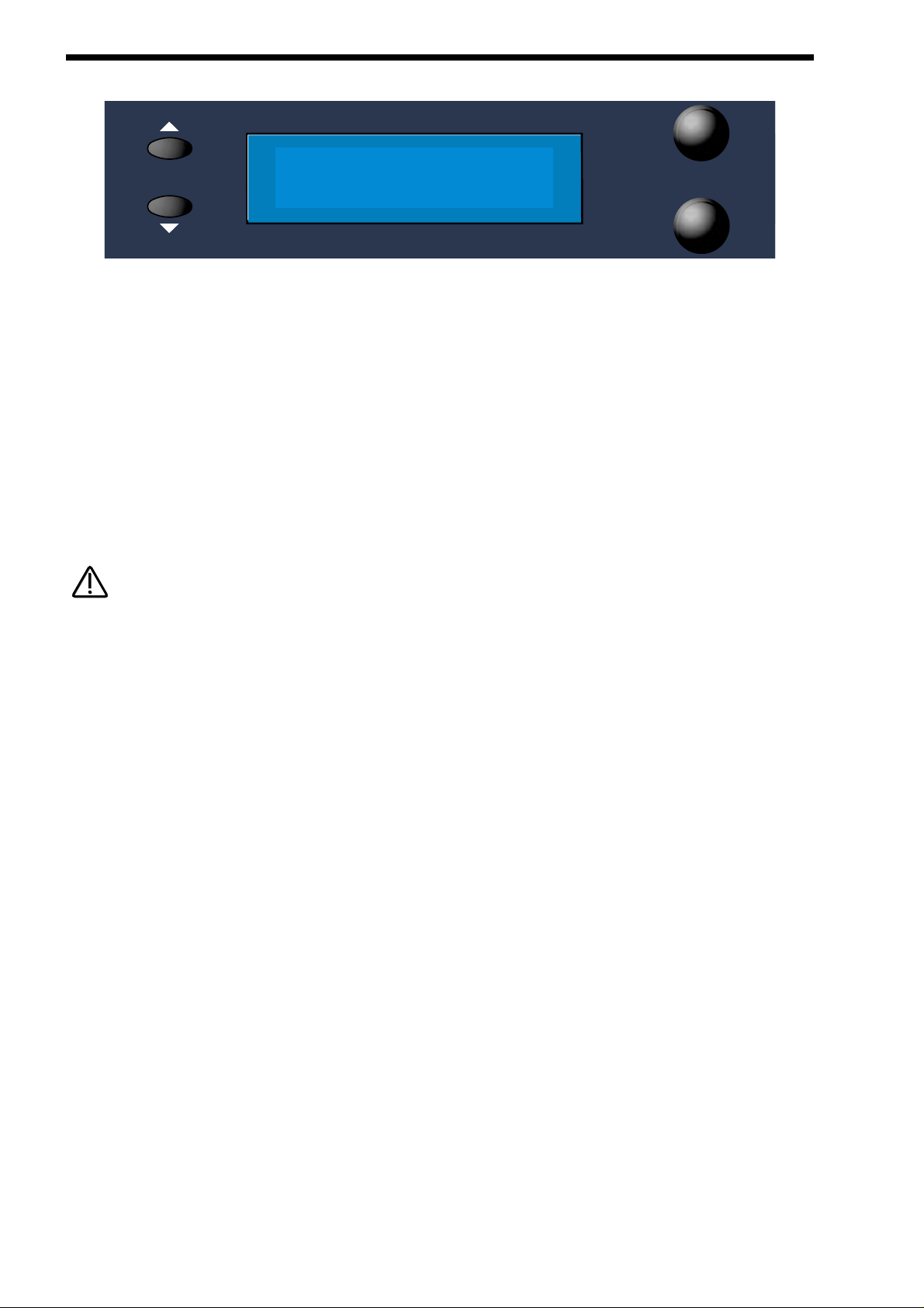
60
DISPLAY SECTION
The display shows the currently selected Performance or Program Name, Bank and Number. When editing Knobs on the front
panel, the relevant parameter description and value is displayed.
Data - Knobs
When editing parameters in Menus, the upper Data Knob on the right of the display is used to edit the higher parameter’s value.
Similarly, the lower parameter’s value can be edited in the same way using the lower Data knob.
Page - Buttons
When editing parameters in Menus, there are usually several “Pages” within each menu. The Default page on pressing any menu
button is the page selected when the Globals were last saved. Higher pages can be accessed by pressing the “Page Up” button
and lower pages can be accessed by pressing the “Page Down” button. Pressing and holding down either of the page buttons will
make the display scroll through the pages automatically. This can be handy for menus (such as the Global Menu) which have quite
a few pages.
The page buttons can sometimes be used in conjunction with the keys on the keyboard to directly enter note values into certain
parameters such as “Range” in Part edit of Performances ( see page 140 for details ) or “Tuning” of Drum Programs (see page
135 for details ).
page
data
NOTE:
NOTE:
Page 61

61
This section contains all the buttons used in the selection of Programs, Performances and Favourites.
Firstly select the desired mode ( Program, Performance or Favourites ) using the Mode section.
To select a specific number requires only 2 button presses - even if the number has 3 digits. For example to select Program 123,
make sure the Supernova II keyboard is in Program Mode ( the Program button is lit ). Now simply press the ‘120’ button followed
by the ‘3’ button in the Keypad section. The display shows:
To select Program 001, make sure the Supernova II keyboard is in Program Mode ( the Program button is lit ). Now simply press
the ‘0’ button on the top row of the Keypad section followed by the ‘1’ button on the bottom row of the Keypad section. The display
shows:
The Bank buttons in the Keypad section change the Bank currently selected. There are 8 Banks of 128 Programs, 4 banks of 128
Performances, 8 Drum Maps (each containing 50 Programs) and 1 Bank of Favourites. Press the Bank Up button once. The display shows:
As there is only 1 Bank of Favourites, the Bank buttons will do nothing in Favourites Mode.
When selecting a Drum Map Program, it is only possible to select programs 000 to 049.
FM EP
Prog BOO1
Its temporate
Prog AOO1
Juno 2OOO
Prog A123
KEYPAD SECTION
bank
01020304050
0123456789
60 70 100 110 12080 90
demo tracks
find global
compare assign
performanceprogram
write
favourites
favourites
NOTE:
NOTE:
NOTE:
NOTE:
Page 62

62
KEYPAD SECTION
In the write procedure the Keypad can be used for entering characters into the soundname. When in the naming page of the write
procedure, the display shows for example:
The name of the sound can be altered using the Data knobs when in this mode, but also by using the Page Up & Down buttons,
the Keypad and the Bank buttons. Pressing the Page Up button while in this mode inserts a space at the cursor position. Pressing
Page Down while in this mode deletes the character at the cursor. The Keypad & Bank buttons also provide useful shortcuts when
in this mode. Pressing the Keypad buttons with or without the 2 bank buttons perform several functions. These are as follows.
Top Row
a b c d e f g h I j k l m
Top Row + Bank Up button (momentary action)
n o p q r s t u v w x y z
Top Row + Bank Down button (latched action)
A B C D E F G H I J K L M
Top Row + Bank Up & Down buttons together
N O P Q R S T U V W X Y Z
Bottom Row
0 1 2 3 4 5 6 7 8 9
Bottom Row + Bank Up button (momentary action)
Space . - # ( ) [ ] ! *
Bottom Row + Bank Down button (latched action)
[Current word 1st] [Current word Last] [Previous word 1st] [Next word 1st] [Previous word last]
[Next word last] [Previous space] [Next space] [1st char] [Last char]
Bottom Row + Bank Up & Down buttons together
[Toggle case char] [Char upper case] [Char lower case] [All words lower case with upper case first letter] [All words upper case] [All
words lower case] [Rotate text left] [ Rotate text right] [Clear text] [Restore text]
Name Prog BOO1
‘FM EP ‘
NOTE:
NOTE:
Page 63

63
This section contains all the Knobs and buttons associated with the Arpeggiator.
Transpose Zone - Button
This button when pressed, makes an area of the keyboard active for real-time Arpeggiator transposition. When active, the Real
Time Transpose zone button is lit. While the real-timetranspose zone is active, playing notes within the zone will transpose
Arpeggiators in real-time (providing their Real-time transpose parameter is set to On – this parameter is accessed in the
Arpeggiator Menu). Notes played within an active real-time transpose zone can only be used for this purpose. They will not trigger
voices in Programs or Parts.
The amount of transposition applied to an Arpeggiator corresponds to the difference in semitones between the note played and the
note defined by the "Arp Transpose Reference Note" (set in the Global Menu). The transposition can be negative as well as positive. For example, if the "Arp Transpose Reference Note" is defined as note C3, playing C#3 will result in the whole arpeggio being
transposed up one semitone from its original key. If Bb3 is played, the whole arpeggio will now be transposed down two semitones
from its original key and so on. To return the arpeggio to its original key (a transposition of zero semitones), it is necessary to play
the same note value as defined by the "Arp Transpose Reference Note".
The size and limits of the real-time transpose zone can be set by pressing the Range button (in the Part Edit section) while the
Arpeggiator Menu is active (the Arp Menu button is flashing).
The whole real-time transpose zone can be detuned by up to –64 / +63 semitones. This can be particularly useful if the defined
real-time transpose zone does not include the "Arp transpose reference note" (set in the Global Menu) to which all real-time transpositions are relatively calculated. The detuning of the real-time transpose zone can be set by pressing the Tune button (in the Part
Edit Section) while the Arpeggiator Menu is active (the Arp Menu button is flashing).
The size and detuning of the real-time transpose zone as well as the Real Time Transpose button status (which determines
whether the zone is active or not) are saved along with the Program when in Program Mode or a Performance if in Performance
Mode.
There is only one real-time transpose zone when in Performance Mode. Playing notes within the zone can potentially affect the
Arpeggiators in every Part simultaneously.
If the keyboard is transposed up or down by using the transpose buttons, the position of the real-time transpose zone is also
moved accordingly.
When the "Arpeggiator Real-time Transpose channel" parameter (set in the Global Menu) is set to a value in the range 1 to 16,
playing a note within the active zone will also result in the transmission of a MIDI note message using the "Arpeggiator Real-time
Transpose channel" MIDI channel. Playing this note information back from a sequencer will then transpose the Arpeggiators in the
same manner as when the notes were originally played on the keyboard.
This feature could alternatively be used to provide an additional keyboard area used solely to control external MIDI equipment –
even when in Program Mode. Of course, any Arpeggiators used by the Program / Performance would probably then need their
realtime transposing parameter disabled.
Arpeggiator
ARPEGGIATOR SECTION
transpose
zone
mute
keysync
on 1 octlatch 2 oct
up down u/d 1 u/d 2menu
3 oct
4 oct
speed
gate time
NOTE:
NOTE:
NOTE:
NOTE:
NOTE:
NOTE:
Page 64
64
ARPEGGIATOR SECTION
Menu - Button
When this button is pressed, a series of pages is available on the display containing parameters relevant to the Arpeggiator.
In the Arpeggiator Section there are 8 pages available. These are selected using the Page Up and Page Down buttons to the left
of the display.
There are a maximum of 2 parameters displayed on any page. One for each line on the display. The upper and lower Data knobs
on the right of the display are used to alter these parameter’s values.
Page 1 looks like so:
The higher parameter is “Pattern bank”. In this case with a value of Mono.
This parameter determines the type of Pattern the Arpeggiator will use. Use the upper Data knob to adjust the value. The “Mono”
Bank contains 128 preset patterns that are Monophonic ( a single note is played at any one time ). The “Poly” Bank contains 128
preset patterns that are Polyphonic ( all the notes played on the keyboard are played at once and transposed ). The “User (U)”
Bank contains 128 patterns which are user programmable from within the Global Menu. Similarly, the “User (V)” and “User (W)”
Banks each have another 128 patterns that are user programmable from within the Global Menu. In the each of the User Pattern
Banks, Patterns 000 to 063 are Monophonic and 064 to 127 are Polyphonic. The range of this parameter is Mono, Poly, User(U),
User(V) & User(W). This parameter is normally memorised with a Program. However, if in Performance mode and the Arp Bank
and Pattern Used parameter on page 1 of the Special menu in the Part Edit section is set to Part, then the parameter is memorised
with a Performance.
The lower parameter is “Pattern no.”. In this case with a value of 120.
This parameter determines which pattern within in the bank specified by the parameter above is used by the Arpeggiator. Use the
lower Data knob to adjust the value The range of this parameter is 000 to 127. This parameter is normally memorised with a
Program. However, if in Performance mode and the Arp Bank and Pattern Used parameter on page 1 of the Special menu in the
Part Edit section is set to Part, then the parameter is memorised with a Performance.
You can assign pattern changes into Favourites locations when this menu page is displayed. Simply select the Pattern bank and
Pattern number you wish to save into a favourite location and press the Assign ( favourites ) button. Now select the favourites location using the Keypad and then press the Assign ( favourites ) button again to write it into the Favourites map.
In Program Mode, the Pattern Bank and Pattern number displayed on this page will possibly be different to the Pattern Bank and
Pattern number displayed when in Performance Mode. In Performance Mode, each Part may have its own pattern settings which
can over-ride the settings noirmally saved within the Program data. The Arp bank and Pattern Used parameter on page 1 of the
Special menu in the Part Edit section determines whether The Program’s Pattern Bank and Pattern number settings are used or
whether the Part’s Pattern Bank and Pattern number settings are used.
Pattern Bank Mono
Pattern no. 12O
NOTE:
NOTE:
NOTE:
NOTE:
Page 65
65
Page 2 looks like so:
The higher parameter is “Latch type”. In this case with a value of Constant.
This parameter determines how the “Latch” function behaves. Use the upper Data knob to adjust the value.
In the “Constant” position, when the “Latch” is “On”, the Arpeggiator always remembers what notes you last played. i.e. If you play
a C triad and then release the keys on the keyboard, the Arpeggiator will not stop, it will continue to sweep through the C triad until
a new set of notes is played, then it will sweep through the new notes until another set it played. etc. etc. In the “Pattern” position,
the Arp will behave as above except that it will stop when it reaches the end of the pattern. This is like playing a loop on a sampler.
Again another powerful feature for live performance. The range of this parameter is Constant & Pattern. This parameter is memorised with a Program.
The lower parameter is “Quantize”. In this case with a value of Mode 1.
This parameter determines if the Arpeggiation played is quantised to the Arp Sync parameter’s time signature or not. Use the lower
Data knob to adjust the value. The Arpeggiator can correct timing errors for you in several different ways. The arpeggiator can correct timing errors by quantising the played notes like a sequencer package ( we will refer to this method as “Quantised”). This corrects the mistakes but can introduce a “Skip” if you play late. i.e. the first note played is on the next quantised step. This is what
would happen in a sequencer as well, but can be not so useful for live performance so we have introduced a kind of “Intelligent
Quantise”. i.e. If you play slightly late those notes will sound immediately and the next step will be quantised. Additionally, things
change if external MIDI Clock is being used. The Arpeggiator reads MIDI Start/Continue Messages. The pattern will start running in
the background when one of these messages is received, but will not make any sound. When the keyboard is played in this condition, the Arpeggiator will then play the correct step in the pattern keeping in step with other data on the sequencer, not start from
the beginning of the pattern. Below is a table showing the different options:
MODES
Off Not quantised.
Mode 1 Quantised.
Mode 2 Intelligently quantised.
Mode 3 Quantised with the pattern locked to the sequencer and/or other quantised Arpeggiators.
Mode 4 Intelligently quantised with the pattern locked to the sequencer and/or other quantised Arpeggiators.
The range of this parameter is Off, Mode 1, Mode 2, Mode 3 & Mode 4. This parameter is memorised with a Program.
In Performances, if more than one Part has a Program with Arpeggiators activated and these Programs have the Arpeggiators
“Quantize” parameter set to active ( modes 1, 2, 3 or 4 ), then activating any Arpeggiator will start all of the Arpeggiators in the
Performance running in Sync with each other ( Although you won’t actually hear them until the correct Range and/or MIDI channel
is triggered ). This means that the phrases created by the separate Arpeggiators are always in sync with each other - even if triggered at different times.
This parameter also affects how the Keysync parameter on the front panel behaves. Refer page 69 for details.
Page 3 looks like so:
Velocity Played
Latch type Constant
Quantize Mode 1
ARPEGGIATOR SECTION
NOTE:
NOTE:
NOTE:
NOTE:
Page 66
66
ARPEGGIATOR SECTION
The higher parameter is “Velocity”. In this case with a value of Played.
This parameter determines how the velocity of the notes played effect the notes in the arpeggiation. Use the upper Data knob to
adjust the value . If this parameter is set to “Played” then the velocities of the notes played on the keyboard will be duplicated in
the notes played in the arpeggiation. If this parameter is set to “Full” then the velocities of the notes played will be at full velocity (
127 ). If this parameter is set to “Half” then the velocities of the notes played will be at half velocity ( 63). If this parameter is set to
“Prog” then the velocities of the notes played will be at the values programmed into the patterns. The range of this parameter is
Played, Full, Half & Prog. This parameter is memorised with a Program.
Page 4 looks like so:
The higher parameter is “Fill in”, in this case with a value of On.
This parameter applies only to Monophonic patterns. It has no affect on polyphonic patterns. Use the upper Data knob to adjust the
value. This parameter determines how the Arpeggiator behaves when you play more or less notes than the Arpeggiator pattern
was written to cope with.
When this parameter is set to “Off”, if you play less notes than the pattern is expecting, the highest note you have played will be
used for all the notes in the pattern data which are greater than your highest played note. If however, you have played more notes
than the pattern was written to cope with, then played notes which are higher than the highest note in the pattern data are not
played.
When this parameter is set to “On”, if you play less notes than the pattern is expecting, your played notes will be used intelligently
for all the notes in the pattern data which are greater than your highest played note. If however, you have played more notes than
the pattern was written to cope with, then played notes which are higher than the highest note in the pattern data are used, replacing their corresponding lower notes every other time the pattern cycles around. Perhaps the best way to understand how this works
is by experimentation - altering the values and number of notes played on the keyboard while a mono arpeggiation is running. The
most musical setting for this parameter is with this parameter set to “On”. The range of this parameter is On & Off. This parameter
is memorised with a Program.
When the Arpeggiator is using one of the standard Up / Down patterns (Mono patterns 000 to 003), Fill-in has a different function.
It can be used to determine how the pattern sweeps through the number of octaves selected. When the Fill-in parameter is set to
"On", the pattern will sweep through all of the available in octaves in a single pass of the pattern. When the Fill-in parameter is set
to "Off", the pattern will use each octave in turn for a single pass of the pattern.
The lower parameter is “Note ordering”, in this case with a value of Played.
This parameter applies only to Monophonic patterns. It has no affect on polyphonic patterns.This parameter determines which note
ordering system is used for the pattern. When set to “Up”, note 1 in the pattern data will refer to the lowest note played on the keyboard, note 2 the next note up and so on. When set to “Down”, note 1 in the pattern data will refer to the highest note played on
the keyboard, note 2 the next note down and so on. When set to “Played”, note 1 in the pattern data will refer to the earliest note
played on the keyboard, note 2 the next note to be played and so on. By adjusting this value, you can in effect, treble the number
of available monophonic patterns you have access to !
The Note ordering parameter is ignored by Mono Patterns 000 to 010 which generate arpeggios by algorithms rather than fixed
pattern data.
Page 5 looks like so:
Sync 16th
[6 MIDI clocks]
Fill in On
Note ordering Played
NOTE:
NOTE:
NOTE:
NOTE:
Page 67

67
The single parameter on this page is “Sync”. In this case with a value of 16th.
This parameter determines the time signature at which the Arpeggiator runs from the Internal or External MIDI Clock.
Use the higher Data knob to adjust the value of this parameter. On the bottom of the display, the number of MIDI clock ‘ticks’ for
the chosen setting is displayed, in this case 6 MIDI clocks. The range of this parameter is 32nd Triplet, 32nd, 16th Triplet, 16th, 8th
Triplet, 16th Dotted, 8th, 4th Triplet, 8th Dotted, 4th, 2nd Triplet, 4th Dotted, 2nd, 1 Bar Triplet, 2nd Dotted, 1 Bar, 2 Bar Triplet, 1
Bar Dotted, 2 Bars, 4 Bar Triplet, 3 Bars, 5 Bar Triplet, 4 Bars, 3 Bar Dotted ( 4.5 Bars ), 7 Bar Triplet, 5 Bars, 8 Bar Triplet, 6 Bars,
7 Bars, 5 Bar Dotted ( 7.5 Bars ), 8 Bars, 6 Bar Dotted ( 9 Bars ), 7 Bar Dotted ( 10.5 bars ) & 8 Bar Dotted ( 12 Bars ). This parameter is memorised with a Program.
Page 6 looks like so:
The single parameter on this page is “Arpeggio notes to:”. In this case with a value of Program & MIDI.
This parameter determines if the Arpeggiation is sent to the Supernova II keyboard’s sound engine, MIDI output or both. Use the
lower Data knob to adjust the value. If this parameter is set to “Program”, then no MIDI note data appears when the Arpeggiator is
played but the Supernova II keyboard is played by the Arpeggiation. If this parameter is set to “Program & MIDI”, then the
Supernova II keyboard is heard playing the Arpeggiation and the Arpeggiation is also output via MIDI. If this parameter is set to
“MIDI Only”, then no sound is heard from Supernova II keyboard when the Arpeggiator is played but the Arpeggiator is output via
MIDI. The range of this parameter is Program Only, Program & MIDI, and MIDI Only. This parameter is memorised with a Program.
Page 7 looks like so:
The higher parameter is "Output MIDI ch", in this case with a value of Input.
This parameter determines which MIDI channel is used to transmit the Arpeggio notes (when the Arpeggiator is configured to send
its notes to "MIDI only" or "Program & MIDI") for the currently selected Program or Part. Use the higher Data knob to adjust this
parameter. If this parameter is set to Input, the MIDI channel used for transmission will be the same MIDI channel as was originally
used to trigger the Arpeggiator (i.e. the same MIDI channel that the Program/Part is set to receive on). If this parameter is set from
1 to 16 then the Arpeggiator's output is transmitted on the MIDI channel specified here. The range of this parameter is Input, 1-16.
This parameter is memorised with a Program.
To record an arpeggiation into a sequencer, we suggest using the following method: With local control set to "Off" and the Output
MIDI ch parameter set to Input Record the chord sequence onto a track on the sequencer. Set the Output MIDI ch parameter to a
suitable MIDI channel different to the Global MIDI channel or any Part ( if you are using the Arp in a Performance ). Create a new
track on the same MIDI channel. Now playing the sequencer will play the chords into the Arp on the correct channel and the
Arpeggio notes will be output on a different channel and you can record them on the new track. No MIDI feedback will occur.
The lower parameter is "Real time trans", in this example with a value of On.
This parameter is used to determine whether the Arpeggiator can be transposed in real-time.Use the lower Data knob to adjust the
value. If set to "On", the whole arpeggio can be transposed in real-time either by a note played inside the real-time transpose zone
on the keyboard (active when the ‘real time transpose’ button is lit) or by notes received on the "Real-time Transpose Channel" (set
in the Global Menu).
The amount of transposition applied to the Arpeggiator corresponds to the difference in semitones between the note played and
the note defined by the "Arp Transpose Reference Note" (also set in the Global Menu). The transposition can be negative as well
as positive. For example, if the "Arp Transpose Reference Note" is defined as note C3, playing C#3 will result in the whole arpeggio being transposed up one semitone from its original key. If Bb3 is played, the whole arpeggio will now be transposed down two
semitones from its original key and so on. To return the arpeggio to its original key (a transposition of zero semitones), it is necessary to play the same note value as defined by the "Arp Transpose Reference Note" (set in the Global Menu).
Output MIDI ch Input
Real time trans On
Arpeggio notes to :
Program & MIDI
ARPEGGIATOR SECTION
Page 68
68
ARPEGGIATOR SECTION
If this parameter is set to "Off", then no real-time transposition will be applied to the arpeggiator. It will continue to play in its original
key even if note information is sent from the real-time transpose zone on the keyboard or the "Real-time Transpose Channel". The
range of this parameter is On & Off. This parameter is memorised with a Program.
SETTING REAL-TIME TRANSPOSE ZONE PARAMETERS
These following parameters can be set only while the Arpeggiator Menu is active (the Arp Menu button is flashing)
REAL-TIME TRANSPOSE ZONE RANGE
This parameter can be edited by pressing the Range button (in the Part Edit section) while the Arpeggiator Menu is active (the Arp
Menu button is flashing). The Range button lights up and the display shows :
The higher parameter is "Kbd t-zone hi" (Keyboard Real-time Transpose Zone highest note), in this example with a value of C2.
Use the upper Data knob to adjust the value. Alternatively, you may edit this parameter by pressing the Page Up button (the Page
Up button lights up while it is pressed) and playing the appropriate note on the keyboard while the button is held down. This parameter represents the highest note value used in the Real-time transpose zone range. The range of this parameter is C-2 to G8.
This parameter is memorised with a Program when in Program Mode, or memorised with a Performance if in Performance Mode.
The lower parameter is "Kbd t-zone lo" (Keyboard Real-time Transpose Zone lowest note), in this example with a value of C1. Use
the lower Data knob to adjust the value. Alternatively, you may edit this parameter by pressing the Page Down button (the Page
Down button lights up while it is pressed) and playing the appropriate note on the keyboard while the button is held down. This
parameter represents the lowest note value used in the Real-time transpose zone range. The range of this parameter is C-2 to G8.
This parameter is memorised with a Program when in Program Mode, or memorised with a Performance if in Performance Mode.
To return to the previous display in the Arpeggiator Menu, press the Range button again (the Range button goes out).
It is possible to define the transpose zone with the highest note set to a value lower than the lowest value. This creates a reverse
zone with a "hole" between the highest note and lowest note where the zone is not active.
REAL-TIME TRANSPOSE ZONE DETUNE
This parameter can be edited by pressing the Tune button while the Arpeggiator Menu is active (the Arp Menu button is flashing).
The Tune button lights up and the display shows :
The only parameter on this page is "Kbd arp transpose zone detune", in this example with a value of +12. Use the lower fast data
knob to adjust the value. This parameter detunes the note value played from the transpose zone by the indicated amount of semitones. Therefore a value of +12 would shift all note values in the whole transpose zone up by one whole octave. This feature can
be particularly useful if the transpose zone range does not include the "Arp Transpose Reference Note" (set in the Global Menu) to
which all real-time transpositions are relatively calculated. The range of this parameter is –64 to +63. This parameter is memorised
with a Program when in Program Mode, or memorised with a Performance if in Performance Mode.
To return to the previous display in the Arpeggiator Menu, press the Tune button again (the Tune button goes out).
Kbd arp transpose
zone detune +12
Kbd t-zone hi C2
Kbd t-zone lo C1
NOTE:
NOTE:
Page 69
69
Page 8 looks like so:
The higher parameter is “Constant pitch”. In this case with a value of Off.
This parameter applies only to Polyphonic patterns. If this parameter is set to “On” then all Arpeggiator note(s) will be sounded at a
fixed pitch regardless of where they have been played from the keyboard. If this parameter is set to “Off” then the transposition of
the notes played by the Arpeggiator will be at the values programmed into the patterns. Use the upper Data knob to adjust the
value. The range of this parameter is On & Off. This parameter is memorised with a Program.
The purpose of this parameter is to allow a sequence of notes to be played in exactly the same musical key regardless of where it
has been triggered from the keyboard (real time transposing can still be used to transpose poly patterns if required). This is especially important if the Arpeggiator is being used to trigger drum patterns on an external Drum Machine or Sampler where each
drum sound has a specific note value. When used in this way, Polyphonic arpeggio patterns can behave in a similar manner to a
‘phrase sequencer’.
When Constant Pitch is activated, the Arp Poly pattern behaves monophonically (i.e. only one note is played for each pattern step,
regardless of how many notes are actually held on the keyboard), since if a chord was played on the keyboard, it would be pointless to send several NOTE ONs to the Program / MIDI OUT each with exactly the same note value.
The lower parameter is “Output ranging”. In this case with a value of Off.
This parameter applies when Arpeggiators are used in Performance Mode. When set to ‘On’, this parameter checks to see if the
Arpeggiator’s final note value (taking into account the current ‘octaves’ shift & any ‘real-time’ transposing) falls within the Part’s
note range parameters. If the final note value falls outside this range, it is not passed on to the Program or MIDI. When Output
Ranging is set to ‘Off’, the final note value will always be passed on to the Program or MIDI. Use the lower Data knob to adjust the
value. The range of this parameter is On & Off. This parameter is memorised with a Program.
When Output Ranging is set to ‘on’, it is possible to obtain interesting Arp pattern variations by adjusting the Part’s range values in
such a way that certain Arpeggiated notes fall outside the Part’s range and are not sounded.
Mute - Button
This button determines if the Arpeggiator is heard in the currently selected Program. When this button is unlit the Arpeggiator is on
and the sound can be heard. In the “Muted” ( Lit ) position, the Arpeggiator is still running in the background, keeping track of
which pattern step would normally be played, but is no longer passing the notes to the Program or MIDI. The sound can no longer
be heard. This parameter is memorised with a Program.
This feature will mute/unmute an external synthesiser being controlled by the arpeggiator via MIDI. (If the Arpeggio notes to: parameter on page 6 of the Arp menu is set to MIDI only or Program & MIDI)
Keysync - Button
This parameter controls the way the Arpeggiator resets itself when new notes are played on the keyboard. In the “Off” position
( unlit ) the cycle of the Arpeggiator is not interrupted when new notes are played on the keyboard, the Arpeggiator simply changes
the notes being played to the new ones. In the “On” position ( lit ) the cycle of the Arpeggiator is reset to the start of its patterns
when any new notes are played on the keyboard. In this condition, if the Quantize parameter on page 2 of the Arp menu is set to
“Off” it behaves like triggering a loop in a sequencer. If the Quantize parameter is set to modes 1 or 3, the reset will occur at the
start of the next step. If Quantize is set to modes 2 or 4, notes played slightly late will reset immediately and following steps will be
in sync. The range of this parameter is On & Off. This parameter is memorised with a Program.
Constant pitch Off
Output ranging Off
ARPEGGIATOR SECTION
NOTE:
NOTE:
NOTE:
NOTE:
NOTE:
NOTE:
Page 70

70
ARPEGGIATOR SECTION
Up - Button
This button assigns the Monophonic Up pattern (Mono pattern 000) to the Arpeggiator when lit. This parameter is memorised with
a Program.
It is not possible to have a different pattern assigned to the Arpeggiator in the Pattern bank and Pattern No parameters of the Arp
Menu when this button is active.
Down - Button
This button assigns the Monophonic Down pattern (Mono pattern 001) to the Arpeggiator when lit. This parameter is memorised
with a Program.
It is not possible to have a different pattern assigned to the Arpeggiator in the Pattern bank and Pattern No parameters of the Arp
Menu when this button is active.
U/D 1 - Button
This button assigns the Monophonic Up/Down 1 pattern (Mono pattern 002) to the Arpeggiator when lit. This parameter is memorised with a Program.
It is not possible to have a different pattern assigned to the Arpeggiator in the Pattern bank and Pattern No parameters of the Arp
Menu when this button is active.
U/D 2 - Button
This button assigns the Monophonic Up/Down 2 pattern (Mono pattern 003) to the Arpeggiator when lit. This parameter is memorised with a Program.
It is not possible to have a different pattern assigned to the Arpeggiator in the Pattern bank & Pattern No parameters of the Arp
Menu when this button is active.
On - Button
This button determines if the Arpeggiator is active or disabled in the currently selected program. Pressing this button makes the
Arpeggiator active and the button will light. Pressing it again will deactivate the Arpeggiator and the light will go out. The range of
this parameter is On & Off. This parameter is memorised with Programs in Program mode and Performances in Performance
mode.
Latch - Button
This button determines the way in which the Arpeggiator remembers which notes you are playing or have played on the keyboard.
When this is “Off” ( unlit ) the Arpeggiator will only sweep through its patterns when you hold down notes on the keyboard. If you
are not playing any notes on the keyboard, no arpeggio will be heard. If the “latch” is set to “On” ( Lit ) the Arpeggiator remembers
what notes you last played (i.e. If you play a C triad and then release the keys on the keyboard, the Arpeggiator will not stop, it will
continue to sweep through the C triad until a new set of notes is played, then it will sweep through the new notes until another set
it played. etc. etc.). The range of this parameter is On & Off. This parameter is memorised with a Program. See page NN for related Latch type details.
NOTE:
NOTE:
NOTE:
NOTE:
NOTE:
NOTE:
NOTE:
NOTE:
Page 71

This parameter can be controlled via the Sustain pedal in Performance Mode. To do so, connect a Sustain Pedal to the Input/sw 1
(Sustain) socket and assign the socket to act as a suitable polarity Footswitch socket on page 9 of the Global Menu. The
Supernova II keyboard can read Sustain information as Arpeggiator latch On / Off, so depressing the Sustain Pedal connected to
the Input/sw 2 socket will switch the Arpeggiator Latch “On”. Releasing the Sustain Pedal will switch it “Off”. For this to work properly, set the “Sustain” parameter in the MIDI button menu for the selected Part to “Arp Latch”. Additionally, this parameter may work
in reverse to the manner described if the incorrect footswitch is used with the keyboard. If this is the case, change the polarity of
the Footswitch socket on page 9 of the Global Menu. In Program Mode, the Sustain Pedal always latches the Arpeggiator while it
is enabled. If the Arpeggiator is not enabled, the Sustain Pedal will act as a normal Sustain.
1 Oct - Button
This parameter determines the number of octaves the Arpeggiator will sweep through. When this button is active ( lit ) the range of
the Arpeggiator’s sweep is 1 octave. This parameter is memorised with a Program
2 Oct - Button
This parameter determines the number of octaves the Arpeggiator will sweep through. When this button is active ( lit ) the range of
the Arpeggiator’s sweep is 2 octaves. This parameter is memorised with a Program.
3 Oct - Button
This parameter determines the number of octaves the Arpeggiator will sweep through. When this button is active ( lit ) the range of
the Arpeggiator’s sweep is 3 octaves. This parameter is memorised with a Program.
4 Oct - Button
This parameter determines the number of octaves the Arpeggiator will sweep through. When this button is active ( lit ) the range of
the Arpeggiator’s sweep is 4 octaves. This parameter is memorised with a Program..
When this parameter is set to use octaves greater than 1,the “Fill in” parameter will affect how the the pattern sweeps through the
octaves on the Monophonic Up/Down patterns ( Mono 000 to 003 ). Refer to the notes on the “Fill in” parameter on page 65 for
details.
It is not possible to have more than one of the Octave buttons selected at any one time.
Speed - Knob
This knob controls the speed at which the Arpeggiator sweeps through is patterns. Anticlockwise the speed is slow, clockwise the
speed is fast. The range of this parameter is 64 bpm to 191bpm. This parameter is memorised with Programs in Program mode
and Performances in Performance mode.
If the synchronisible features such as the LFOs are synchronised to Internal Clock, then as well as controlling Arpeggiator speed,
this control sets the speed of the Internal Clock ensuring the LFOs, Delay etc. will be synchronised with the Arpeggiator at whatever time signature has been selected in the LFOs, Delay etc. Note that this applies only if the MIDI Clock parameter in the Global
Menu is not set to External.
Gate time - Knob
This knob controls the “gate” time or duration of the notes being played by the Arpeggiator. Small values of gate timeproduce a
“Staccato” effect while large values produce a “Legato” effect to the Arpeggiation. Anticlockwise, the gate time is very short, clockwise the gate time is long. The range of this parameter is 1% to 99%. This parameter is memorised with Programs.
71
ARPEGGIATOR SECTION
NOTE:
NOTE:
NOTE:
NOTE:
NOTE:
NOTE:
NOTE:
NOTE:
Page 72

72
OSCILLATOR SECTION
This section contains all the knobs and buttons associated with the Oscillators and Mixer.
Menu - Button
When this button is pressed, a series of pages is available on the display containing parameters relevant to the Oscillators.
In the Oscillator Menu there are 6 pages available. These are selected using the Page Up and Page Down buttons to the left of the
display.
There are a maximum of 2 parameters displayed on any page. One for each line on the display. The upper and lower Data knobs
on the right of the display are used to alter these parameter’s values.
Page 1 looks like so:
The higher parameter is “MWheel LFO 1 amt”. In this case with a value of +10.
This parameter determines how the Mod Wheel affects the amount of LFO1 modulation on the currently selected Oscillator. Use
the upper Data knob to adjust the value of this parameter. With this parameter it is possible to set the amount of modulation individually for each oscillator. The range of this parameter is -64 to +63. This parameter is memorised with a Program.
Mod Wheel LFO Amt does not apply to the 1*3, 2*3 or Noise buttons. If you attempt to access this parameter when these buttons
are selected, the display will show “Menu Only Available For Osc 1,2 or 3” whilst the adjustment is being made then the display will
revert back to the last edited parameter.
The lower parameter is “AT LFO 1 amt”. In this case with a value of +10.
This parameter determines how the Aftertouch affects the amount of LFO1 modulation on the currently selected Oscillator. Use the
lower Data knob to adjust the value of this parameter. With this parameter it is possible to set the amount of modulation individually
for each oscillator. The range of this parameter is -64 to +63. This parameter is memorised with a Program.
Aftertouch LFO 1 Amt does not apply to the 1*3, 2*3 or Noise buttons. If you attempt to alter this parameter when these buttons
are selected, the display will show “Menu Only Available For Osc 1,2 or 3” whilst the adjustment is being made then the display will
revert back to the last edited parameter.
MWheel LFO1 amt +1O
ATouch LFO1 amt +1O
Oscillators
menu
solo
destination source
copy
modulation
sources
lfo 1
lfo 2
env 2
env 3
wheelmodportamento
osc 1
square saw
oct/semi
osc 2 osc 3
special
cents
fm fm fm
voice controltune
menu
mix
noise1*3 2*3
pitch
width
sync
hardness
level
NOTE:
NOTE:
NOTE:
NOTE:
Page 73

73
Page 2 looks like so:
The higher parameter is “Formant width”. In this case with a value of 010.
This parameter determines how much Formant Width is applied to the currently selected Oscillator. Use the upper Data knob to
adjust the value of this parameter. With this parameter it is possible to set the amount of modulation individually for each oscillator.
Refer to page 6 in the “About Analogue Synthesis” section for details on this parameter. The range of this parameter is 000 to 127.
This parameter is memorised with a Program.
Formant Width does not apply to the 1*3, 2*3 or Noise buttons. If you attempt to alter this parameter when these buttons are
selected, the display will show “Menu Only Available For Osc 1,2 or 3” whilst the adjustment is being made then the display will
revert back to the last edited parameter.
The lower parameter is “Sync skew”. In this case with a value of +10.
This parameter determines how much of the Sync Skew effect is applied to the currently selected Oscillator. Use the lower Data
knob to adjust the value of this parameter. With this parameter it is possible to set the amount of modulation individually for each
oscillator. Refer to page 6 in the “About Analogue Synthesis section” for details on this parameter. The range of this parameter is
-64 to +63. This parameter is memorised with a Program.
Sync Skew does not apply to the 1*3, 2*3 or Noise buttons. If you attempt to alter this parameter when these buttons are selected,
the display will show “Menu Only Available For Osc 1,2 or 3” whilst the adjustment is being made then the display will revert back
to the last edited parameter.
Page 3 looks like so:
The higher parameter is “Sync key follow”. In this case with a value of 010.
This parameter determines how the “Virtual” Sync oscillator is transposed across the keyboard for the currently selected Oscillator.
Use the upper Data knob to adjust the value of this parameter. With this parameter it is possible to set the amount of modulation
individually for each oscillator. Refer to page 6 in the “About Analogue Synthesis section” for details on this parameter. The range
of this parameter is 000 to 127. This parameter is memorised with a Program.
Sync Key Follow does not apply to the 1*3, 2*3 or Noise buttons. If you attempt to alter this parameter when these buttons are
selected, the display will show “Menu Only Available For Osc 1,2 or 3” whilst the adjustment is being made then the display will
revert back to the last edited parameter.
The lower parameter is “Pitch bend range”. In this case with a value of +10.
This parameter determines how the Pitch Bend Wheel affects the pitch of the currently selected Oscillator. Use the lower Data
knob to adjust the value of this parameter. With this parameter it is possible to set the pitch bend range individually for each oscillator allowing the creation of effects like using the Pitch bend control to bend into a chord. The range is -12 to +12 in semitone steps.
This parameter is memorised with a Program.
Pitch bend Range does not apply to the 1*3, 2*3 or Noise buttons. If you attempt to alter this parameter when these buttons are
selected, the display will show “Menu Only Available For Osc 1,2 or 3” whilst the adjustment is being made then the display will
revert back to the last edited parameter.
Sync key follow O1O
Pitch bend range +1O
Formant width O1O
Sync skew +1O
OSCILLATOR SECTION
NOTE:
NOTE:
NOTE:
NOTE:
NOTE:
NOTE:
NOTE:
NOTE:
Page 74

74
OSCILLATOR SECTION
Osc1- Button
Osc2- Button
Osc3- Button
1*3 - Button
2*3 - Button
Noise - Button
1*3 - FM - Button
2*3 - FM - Button
Noise - FM - Button
All these buttons “select” which oscillator is going to be manipulated by the other parameters in this section. the Osc 1 button
selects Oscillator 1 for editing, the Osc 2 button selects Oscillator 2 for editing, the Osc 3 button selects Oscillator 3 for editing, the
1*3 button selects the output of the Ring Modulator between Oscillators 1 & 3 for editing, the 2*3 button selects the output of the
Ring Modulator between Oscillators 2 & 3 for editing and the Noise button selects the Noise Generator for editing.
The 1*3 - FM button changes the modulation between Oscillators 1 & 3 from Ring Modulation to FM, the 2*3 - FM button changes
the modulation between Oscillators 2 & 3 from Ring Modulation to FM and theNoise - FM button changes the modulation between
Oscillator 3 & the Noise source from Ring Modulation to FM.
To adjust the tuning setting of Oscillator 1 press the “Osc 1” button ( it will light up indicating it is selected ). Now turn the “Oct /
Semi” knob within the Oscillator section. Adjusting the knob will now change the octave and semitone tuning setting of only
Oscillator 1. The Display will remain like this until another sound source is selected or another parameter is adjusted, in which case
it will update to display the new parameter. To return to the display of the Program / Performance name and number press the
appropriate Program or Performance button.
Only one Oscillator or one of the Ring Modulator / FM or the Noise Source can be selected / edited at one time.
Some parameters do not apply to all sound sources. i.e. The “Octave / Semitone” parameter has no effect on the Noise generator.
If this is the case, the display will read “Not Available” when the control is adjusted.
Solo - Button
This button is similar to a “solo” button on a mixing console. Pressing this button activates the solo function ( The button is lit ) and
only the currently selected sound source will be heard. This is useful when for example, auditioning the single Oscillator settings
within a sound. To return to normal operation press the solo button again. ( unlit )
Copy - Button
This button activates an Oscillator Copying utility. This allows the complete settings of one Oscillator to be quickly copied to another Oscillator. Pressing the button (The button is lit ) when Oscillator 1 is selected activates the copying function for Oscillator 1’s
parameters. The display shows:
It is now a simple matter of pressing the destination ( the Oscillator that you wish to copy oscillator 1’s settings to ). i.e. Press
Oscillator 2 button and the display shows:
All of Oscillator 2’s settings will now be identical to Oscillator 1’s settings.
Oscillator 1 copied
to oscillator 2
Copy oscillator 1
to ?
NOTE:
NOTE:
NOTE:
NOTE:
Page 75

75
It is only possible to copy an Oscillator to another Oscillator.
To exit this mode without copying an Oscillator, press the copy button again. (the Copy button is unlit )
Saw Waveform - Button
Sq waveform - Button
Special Waveform - Button
This is a selection of oscillator waveforms for the oscillator currently selected with the Osc 1, 2, & 3 buttons. To adjust the waveform of oscillator 1, press the “Osc 1” button and select the waveform required. The selected waveform button will light. The Saw
button selects a Sawtooth waveform, the Sq button selects a Square waveform and the Special button selects either Audio input 1,
Audio input 2 or the DoubleSaw “special” waveform.
When the DoubleSaw wave form is selected, the currently selected Oscillator actually becomes 2 Saw waves which can be independently phase shifted or detuned with the use of an LFO. If all Oscillators are set to Double Saw then each voice has effectively
6 Oscillators. This has no effect on total Polyphony and can allow Unison type sounds to be created without the need to use the
Unison feature, thereby saving voices. Of course, it is still possible to Unison a Double Saw Program to create truly HUGE sounds
( Whoever said size does not matter is deluding themselves! ).
All the functions like Mix, Pitch, Sync and Hardness still apply, but these parameters will modulate both Saw waves simultaneously.
Sync sounds can cause clicks when LFOs are used to detune Double Saw waves. This will happen when the modulating LFO is
set to anything BUT Tri waves.
Special Waveform - Button
When the Special button in the Oscillator Section is pressed the Display shows:
The only parameter is “Special Wave” In this case with a value of Double saw.
This parameter determines which special waveform the currently selected oscillator will use. Use the lower Data knob to adjust this
parameter. If this parameter is set to Audio input (1), Audio input 1 will be substituted for the standard Oscillator waveform. If this
parameter is set to Audio input (2), Audio input 2 will be substituted for the standard Oscillator waveform. If this parameter is set to
Double saw, the Double saw waveform as described above will be substituted for the standard Oscillator waveform. The range of
this parameter is Audio input (1), Audio input (2) & Double Saw. This parameter is memorised with a Program.
How to use the Double Saw waveform
Width - Button
Level- Knob
When the Double Saw wave is selected, the Width part of the matrix is used to control the “Difference” in phase between the 2
Saw waves. The Level control controls the static phase difference between the 2 Saw waves. When this is set to 000, there is no
difference between the waves and so at this setting, Double Saw waves sound identical to a standard Saw wave.
Special waveform
Double saw
OSCILLATOR SECTION
NOTE:
NOTE:
NOTE:
NOTE:
NOTE:
NOTE:
NOTE:
NOTE:
Page 76

76
OSCILLATOR SECTION
As both waves are adding together exactly when no phase difference is set between the 2 Saw waves, the resulting “Single” Saw
wave is twice as loud as a standard Saw wave. This can be handy when severe filtering is being employed.
When this parameter is set to a positive value, the phase difference between the 2 Saw waves is modulated by a positive amount.
Similarly negative values produce a negative phase shift between the 2 Saw waves. Fully clockwise or fully anticlockwise the
phase shift is 180
O
,
shifted positive or negative respectively. The range of this parameter is -64 to +63. This parameter is memo-
rised with a program.
The key way to understand how this works is to understand that detuning can be expressed as continually accelerating ( or decel-
erating ) phase shift. When looking at the waves of detuned Oscillators on an Oscilloscope it can be clearly seen that one waveform accelerates ( or decelerates - the result is the same ) in respect to the other. The greater the detuning, the greater the difference in phase shift acceleration or deceleration between the two Oscillators.
So how is this done? The answer is with an LFO. Because the modulation of an LFO has been tailored to modulate a Double Saw
wave exactly from 0
O
phase shift to 360Owhen set to FULLY positive or negative modulation ( 180Ophase shift of modulation of
each positive and negative cycle are used providing 360Oof phase shift ), continuous detuning effects can be reproduced.
To create straight pitch shift detuning effects, use a Saw wave on the modulating LFO. Moderate speed is required. Typically 11 0
when set to “Slow”. Slow speeds produce small pitch shifts. Fast speeds produce large ones.
To create chorus like detuning effects, use a Tri wave on the modulating LFO. Fairly slow speeds are all that is required.
Anything less than FULL positive or negative modulation will result in a less than 360
O
phase shift and clicks will occur.
Tips and Tricks
Try setting the modulating LFOs Keysync parameter to Keysync to get really percussive attacks to Double Saw sounds. This simulates all the Oscillators starting in phase. Setting this parameter to Freewheel means all Oscillators will start at random phase locations.
Below is an example of how to set up a detuning effect using a Double Saw wave.
Width - Button
Mod Depth - Knob
LFO 1 - Button
This combination can be used to create a Pitch shift using LFO 1. The first this that needs to be done is set the LFO ( in this case
LFO 1 ) to a Saw wave running at a moderate speed, i.e. 110. When set to Slow, Turning the Mod Depth Knob clockwise introduces a pitch shift in one of the Saw waves in a positive direction. Turning the Mod Depth Knob anticlockwise introduces a pitch
shift in one of the Saw waves in a negative direction. In the “Mid” position there is no modulation at all. The range of this parameter
is -64 to +63.
This is actually set up in Program D123 “DOUBLE SAW Init”. In this program, LFO1 is used positively and negatively on 2 oscillators and LFO2 is used at a slightly different speed to make sure all 6 oscillator waves are at different pitches.
The detune effect will not be smoothly produced if anything less than a modulation level of -64 to +63 is used. Anything else may
produce clicky artifacts, but these in themselves may be interesting.
These buttons do not apply to the Ring Mod Oscillators ( 1*3 & 2*3 ) or the Noise Generator.
NOTE:
NOTE:
NOTE:
NOTE:
NOTE:
NOTE:
NOTE:
NOTE:
NOTE:
NOTE:
Page 77

77
Octave/Semi - Knob
Cents - Knob
These knobs determine the Octave setting, Semitone transposition and fine tuning of the currently selected Oscillator.
Turning the Octave/Semi knob clockwise raises the pitch of the selected oscillator by one semitone per click. Similarly, turning the
Octave/Semi knob anticlockwise lowers the pitch of the selected oscillator by one semitone per click.The total amount of transposition available is +/- 3 Octaves.
When this knob is turned clockwise one click from the 0 oct 0 semi setting position, the display shows:
When this knob is turned anticlockwise one click from the 0 oct 0 semi setting position, the display shows:
When this knob is turned clockwise one click from the 0 oct +11 semi setting position, the display shows:
When this knob is turned anticlockwise one click from the -1 oct 0 semi setting position, the display shows:
Of course the upper data knob will alter octaves and scale the semitones appropriately. Similarly the semitone values of +/- 12
should be interpreted as octave shifts and the semitone value returned to 0.
The Cents knob will shift the selected oscillator up 63 cents when turned fully clockwise & down 64 cents when turned fully anticlockwise. These parameters are memorised with a Program.
Menu - Button (V oice control section )
Page 1 looks like so:
The higher parameter is “Porta type”. In this case with a value of Glissando.
This parameter determines If the Portamento effect is smooth or stepped in semitones. Use the upper Data knob to adjust the
value of this parameter. In the Porta position, the Portamento effect is smooth. Notes glide smoothly from one pitch to another
determined by the Porta Time setting. In the Gliss position, the Portamento effect is Glissando. Notes glide in semitone steps from
one pitch to another determined by the Porta Time setting. The range is Porta & Gliss. This parameter is memorised with a
Program.
Porta type Glissando
Porta mode Exp
Octave -2
Semitones +11
Octave +1
Semitones O
Octave -1
Semitones +11
Octave O
Semitones +1
OSCILLATOR SECTION
Page 78
78
OSCILLATOR SECTION
The lower parameter is “Porta mode”. In this case with a value of Exp.
This parameter determines if the glide curve of the Portamento effect is Linear or Exponential. Use the lower Data knob to adjust
the value of this parameter. Some synthesisers like the TB303* have an Exponential curve which gives them a certain “Character”
to the way slides are performed. On the other hand for Portamento lead, Linear is the norm. The range is Lin & Exp. This parameter is memorised with a Program.
Page 2 looks like so:
The higher parameter is “Poly mode”. In this case with a value of Mode 1.
This parameter determines If new voices are used when the same note is played. Use the upper Data knob to adjust the value of
this parameter. In the “Mode 1” position, the voice allocation behaves like most modern synthesisers. i.e. a new voice is allocated
to every new note played even if the new note is being already played by another voice. In the “Mode 2” position the voice allocation behaves like vintage 8 / 6 voice analogue synthesisers. i.e. If a new note is played that is already being played by another
voice, the existing voice is soft retriggered and plays the new note. No new voice is allocated. The range is Mode 1 & Mode 2. This
parameter is memorised with a Program.
The lower parameter is “Osc mode”. In this case with a value of Percussive.
This parameter determines if the Oscillators phase are reset at note on time or not. Use the lower Data knob to adjust the value of
this parameter. In the “Percussive” position, the Oscillators are reset at note on. This makes it possible to create “Punchy” basses
and Drum sounds. In the “Ensemble” position, all the Oscillators are free running and this allows the creation of fat string sounds
etc. The range is Percussive & Ensemble. This parameter is memorised with a Program.
If this parameter is set to Ensemble, then the Osc start phase parameter on page 6 of this menu will not have any effect as this
makes all oscillators freewheel. No phase control is operational.
Page 3 looks like so:
The only parameter on this page is “Glide type”. In this case with a value of Normal Glide.
This parameter determines how the Portamento is controlled. Turning the lower Data knob fully anticlockwise sets this parameter to
the “Normal” position. In this mode, the Portamento behaves normally. Turning this knob clockwise selects the “AutoGlide” option”.
In this mode, the Portamento will be switched off when notes are played with a gap in-between them. However, when Legato(overlapping) notes are received, the Portamento effect is switched on. This is particularly useful as it makes TB303* type glides in a
sequencer very easy to program by simply overlapping the notes where you want the glide to occur. From this position, turning the
knob clockwise brings up the Preglide options. When these options are selected, a “Preglide” is applied to the pitch of the oscillators starting at a pitch determined by the PreGlide selected and gliding up or down to the normal pitch. The time it takes to do this
is determined by the Portamento time. The Preglide is triggered with every note received. Below is a description of the different
types of PreGlide available.
2 semitones down A Glide from 2 semitones down is applied to the Oscillators.
2 semitones up A Glide from 2 semitones up is applied to the Oscillators.
5 semitones down A Glide from 5 semitones down is applied to the Oscillators.
5 semitones up A Glide from 5 semitones up is applied to the Oscillators.
7 semitones down A Glide from 7 semitones down is applied to the Oscillators.
7 semitones up A Glide from 7 semitones up is applied to the Oscillators.
12 semitones down A Glide from 12 semitones down is applied to the Oscillators.
12 semitones up A Glide from 12 semitones up is applied to the Oscillators.
Glide type
Normal glide
Poly mode Mode 1
Osc mode Percussive
NOTE:
NOTE:
Page 79

The range of this parameter is Normal Glide, Auto Glide, 2 semitones down, 2 semitones up, 5 semitones down, 5 semitones up, 7
semitones down, 7 semitones up, 12 semitones down& 12 semitones up. This parameter is memorised with a Program.
You cannot have different settings of this parameter for different Oscillators.
* TB303 is a trademark copyright of Roland Corp. Japan.
Page 4 looks like so:
The higher parameter is “Unison”. In this case with a value of Off.
This parameter activates the Unison mode. Use the upper Data knob to adjust the value of this parameter. When this parameter is
set to Off, only one voice is used per note in a Program. When this parameter is set to On, more than one voice is used per note in
a Program. The number of voices used per note is determined by the Unison Mode parameter on the lower line of this page. The
Detuning of the voices is controlled by the Unison Detune parameter on the next menu page. The range of this parameter is On &
Off. This parameter is memorised with a Program.
The Unison mode will not appear to do very much unless the Unison detune parameter has a value greater than 0.
The lower parameter is “Unison mode”. In this case with a value of 2 voice.
This parameter determines the number of voices used per note when the Unison mode is active. Use the lower Data knob to adjust
the value of this parameter. Larger values tend to create fatter sounds. The range of this parameter is 2 to 8. This parameter is
memorised with a Program.
Large voice settings of the Unison mode can be quite polyphony hungry. For example a setting of 8 voice will produce a fat sound
but 3 notes will consume 24 voices. Bear in mind the Polyphony available fitted to your Supernova II Keyboard.
Page 5 looks like so:
The higher parameter is “Unison detune”. In this case with a value of 8.
This parameter determines the relative detuning of voices when the Unison mode (detailed above) is active. Use the upper Data
knob to adjust this parameter. When this parameter is set to low values, only small shifts in tuning are applied to the different voices. When this parameter is set to high values, larger shifts in tuning are applied to the different voices. The range of this parameter
is 000 to 127. This parameter is memorised with a Program.
The lower parameter is “VCO drift”. In this case with a value of 064.
This parameter determines the how the tuning of all the oscillators behave. Use the lower Data knob to adjust this parameter.
When this parameter is set to 000 the tuning between the oscillators is perfect. This is the case on “DCO” ( Digitally Controlled
Oscillator ) synthesisers such as the Roland Juno 106* or Juno 60*. Tuning this parameter up gradually increases the classic
“VCO” ( Voltage Controlled Oscillator ) characteristics. At relatively low levels this parameter is similar to a quality VCO synth with
all its oscillators tuned up. At 127 the oscillators are quite out of tune and it sounds like a VCO synth in need of a service! The
range of this parameter is 000 to 127. This parameter is memorised with a Program.
* Juno 106 & Juno 60 are trademarks copyright of Roland Corp. Japan.
Unison detune OO8
VCO drift O64
Unison Off
Unison mode 2 voice
79
OSCILLATOR SECTION
NOTE:
NOTE:
NOTE:
NOTE:
NOTE:
NOTE:
Page 80

80
OSCILLATOR SECTION
Page 6 looks like so:
The higher parameter is “Osc start phase”. In this case with a value of 000.
This parameter determines the phase at which the oscillators start at when a key is pressed. Use the upper data knob to adjust the
value of this parameter. When this parameter is set to 000, the start phase of the oscillators is at 0Þ. When set to 32, the start
phase of the oscillators is 90
O
. When set to 64, the start phase of the oscillators is 180O. When set to 96, the start phase of the
oscillators is 270Oand when set to 127, the start phase of the oscillators is approx. 355O. The phase is smoothly adjustable from 0
O
to nearly 360Owith this parameter. The range of this parameter is 000 to 127. This parameter is memorised with a Program.
This parameter will not have any effect at all if the Osc mode parameter on page 2 of this menu is set to Ensemble as this makes
all oscillators freewheel, in which case no phase control is operational.
This parameter is useful in the creation of “Percussive” sounds or drums when set to either 32 (= 90
O
) or 96. (= 270O)
The lower parameter is “Drum one-shot”. In this case with a value of Off.
This parameter can simulate the ‘One shot’ feature found on samplers. Use the lower data knob to adjust the value of this parameter. When this parameter is set to Off, Note Off messages received from the keyboard or MIDI will force the Envelopes to jump
immediately to their Release stage. This is normal Envelope operation. When this parameter is set to On, as soon as a note is triggered from the keyboard or from MIDI, the whole note envelope will be sounded. Any Note Off messages from the keyboard or
MIDI will have no effect on the sound and will not force the Envelopes to immediately jump to their Release stages. This parameter
is memorised with a Program.
This parameter is especially useful when creating drum sounds and using Drum Maps with a sequencer. It is possible that "note
dropouts" can occur, especially when repetitive notes occur (Such as snare rolls). This is because some sequencers occasionally
get the note on/off messages out of sequence. It is not a fault with the Supernova II keyboard but rather the sequencer. This is a
typical example of what happens : when a snare roll of say 16th notes with a gate time of 16ths is programmed into a sequencer,
the expected Midi output would be as follows:
Note on - (gap of 1 16th) - Note off, Note on - (gap of 1 16th) - Note off, Note on - (gap of 1 16th) - Note off, etc.
Ocassionally, what actually happens is :
Note on - (gap of 1 16th) - Note off, Note on - (gap of 1 16th) - Note on, Note off - (gap of 1 16th) - Note off, etc.
This happens presumably because as far as the sequencer is concerned, certain Note off and the Next note on events happen in
theory at the same time. Most of the time the sequencer will output them in the right order but occasionally it will get the order
wrong, resulting in the odd note dropping out.Setting the Drum one-shot parameter to On eliminates this problem, since Note Off
messages are effectively ignored and therefore notes will never appear to dropout. Another solution is to either make the Gate time
(Note length) of the notes less than the distance between the notes (forcing the sequencer to output the Note on and off messages
correctly).
Portamento - Knob
This knob adjusts the Portamento effect on the currently selected Program. Fully anticlockwise no Portamento is heard. Turning the
knob clockwise brings in the Portamento effect and notes will smoothly glide from one pitch to the next. The range of this parameter is 000 to 127. This parameter is memorised with Programs.
The Portamento effect will only work when the polyphony of the Program / Part is set to Mono.
Osc start phase OOO
Drum one-shot Off
NOTE:
NOTE:
NOTE:
NOTE:
NOTE:
NOTE:
NOTE:
NOTE:
Page 81
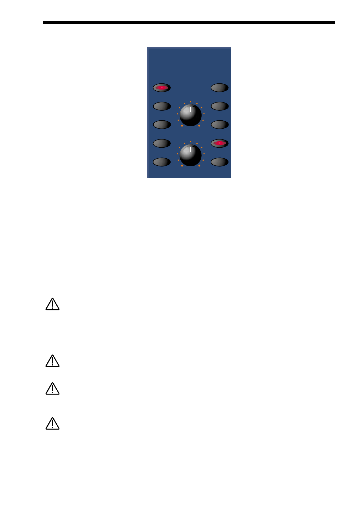
81
Oscillator Modulation Matrix
This is an extremely powerful feature of the Supernova II keyboard. These controls affect the modulation of the currently selected
oscillator or sound source. The buttons on the left are all “Destinations”. They can all be modulated by the “Sources” which are the
buttons on the right. The amount of modulation applied from any source is determined by the setting of the Mod Depth Knob. This
can be either Positive modulation ( Turning the Mod Depth Knob Clockwise ) or Negative modulation ( Turning the Mod Depth
Knob Anticlockwise ). Additionally, there is a manual Level Knob that allows a static “Offset” or “level” to be applied to any of the
destinations.
For example, to adjust the level of the “Harden” setting of Oscillator 1 press the “Osc 1” button ( it will light up indicating it is selected ) and then press the “Harden” button within the modulation section to define the modulation destination. Now adjusting the Level
knob will change the Harden setting of Oscillator 1.
Similarly, to adjust the level of the envelope 3 modulation of the “Harden” setting of Oscillator 1, press the “Osc 1” button ( it will
light up indicating it is selected ) and then press the “Harden” button within the modulation section to define the modulation destination. Press the Env 3 button to define the modulation source. Now adjusting the Mod depth knob clockwise will modulate the
Harden setting of Oscillator 1 by envelope 3.
This makes it possible for all modulation sources to affect any one destination in varying amounts and even in different polarities.
The display will change to indicate the parameter which has been selected and show the newly edited value. The Display will stay
like this until another parameter is adjusted, in which case it will change to display the new parameter. To return to the display of
the Program / Performance name and number, press the Program or Performance button.
Only one source and destination can be edited at one time.
Even though only one source and destination combination can be edited at one time, All available combinations can happen at the
same time.
Some combinations do not apply. For example, Pulse Width Modulation of Noise Generator. When such a parameter is edited the
display shows “Not Available” and no audible effect is heard.
OSCILLATOR SECTION
modulation
destination source
mix
pitch
width
sync
hardness
level
lfo 1
lfo 2
env 2
env 3
wheelmod
NOTE:
NOTE:
NOTE:
NOTE:
NOTE:
NOTE:
NOTE:
NOTE:
Page 82

82
OSCILLATOR SECTION
Possible Combinations and the effects Produced.
All these parameters are memorised with a Program.
Mix - Button
Level- Knob
This combination controls the Volumeof the selected Oscillator, Noise Generator or Ring Modulator. Turning the Level Knob fully
clockwise turns the selected sound source to full volume & fully anticlockwise turns the selected sound source to off ( No Volume ).
The range of this parameter is 000 to 127.
Mix - Button
Mod Depth - Knob
LFO 1 - Button
This combination controls the modulation of the Mix of the selected Oscillator, Noise Generator or Ring Modulator by LFO 1.
Turning the Mod Depth Knob fully clockwise introduces Mix modulation from LFO 1 to the selected sound source in a Positive
direction. Turning the Mod Depth Knob fully anticlockwise introduces Mix modulation from LFO 1 to the selected sound source in a
Negative direction. In the “Mid” position there is no modulation at all. The range of this parameter is -64 to +63.
Mix - Button
Mod Depth - Knob
LFO 2 - Button
This combination controls the modulation of the Mix of the selected Oscillator, Noise Generator or Ring Modulator by LFO 2.
Turning the Mod Depth Knob fully clockwise introduces Mix modulation from LFO 2 to the selected sound source in a Positive
direction. Turning the Mod Depth Knob fully anticlockwise introduces Mix modulation from LFO 2 to the selected sound source in a
Negative direction. In the “Mid” position there is no modulation at all. The range of this parameter is -64 to +63.
Mix - Button
Mod Depth - Knob
ENV 2 - Button
This combination controls the modulation of the Mix of the selected Oscillator, Noise Generator or Ring Modulator by ENV 2.
Turning the Mod Depth Knob fully clockwise introduces Mix modulation from ENV2 to the selected sound source in a Positive
direction. Turning the Mod Depth Knob fully anticlockwise introduces Mix modulation from ENV2 to the selected sound source in a
Negative direction. In the “Mid” position there is no modulation at all. The range of this parameter is -64 to +63.
Mix - Button
Mod Depth - Knob
ENV 3 - Button
This combination controls the modulation of the Mix of the selected Oscillator, Noise Generator or Ring Modulator by ENV3.
Turning the Mod Depth Knob fully clockwise introduces Mix modulation from ENV3 to the selected sound source in a Positive
direction. Turning the Mod Depth Knob fully anticlockwise introduces Mix modulation from ENV3 to the selected sound source in a
Negative direction. In the “Mid” position there is no modulation at all. The range of this parameter is -64 to +63.
Mix - Button
Mod Depth - Knob
Wheel - Button
This combination controls the modulation of the Mix of the selected Oscillator, Noise Generator or Ring Modulator by the Mod
Wheel. Turning the Mod Depth Knob fully clockwise introduces Mix modulation from the Mod Wheel to the selected sound source
in a Positive direction. Turning the Mod Depth Knob fully anticlockwise introduces Mix modulation from the Mod Wheel to the
selected sound source in a Negative direction. In the “Mid” position there is no modulation at all. The range of this parameter is -64
to +63.
Pitch - Button
NOTE:
NOTE:
Page 83

83
Level- Knob
This combination controls the Pitch Tracking of the selected oscillator. Turning the Level Knob fully clockwise makes the selected
Oscillator track the keyboard in the normal way. i.e. Notes played one octave apart keyboard are transposed one octave apart. In
the “Mid” position notes played one octave apart on the keyboard are transposed 1/2 an octave apart and fully anticlockwise notes
played one octave apart on the keyboard produces no transposition at all. This can be useful for Ring Mod effects. The range of
this parameter is 000 to 127.
This does not apply to the Noise, 1*3 & 2*3 Ring Modulator outputs. No audible effect to these sound sources will be heard if an
attempt is made to adjust this parameter when these sound sources are selected.
Pitch - Button
Mod Depth - Knob
LFO 1 - Button
This combination controls the Pitch Modulation of the selected Oscillator by LFO 1. Turning the Mod Depth Knob fully clockwise
introduces Vibrato from LFO 1 to the selected Oscillator in a Positive direction. Turning the Mod Depth Knob fully anticlockwise
introduces Vibrato from LFO 1 to the selected Oscillator in a Negative direction. In the “Mid” position there is no modulation at all.
The range of this parameter is -64 to +63.
This does not apply to the Noise, 1*3 & 2*3 Ring Modulator outputs. No audible effect to these sound sources will be heard if an
attempt is made to adjust this parameter when these sound sources are selected and the display will show “Not Available”.
Pitch - Button
Mod Depth - Knob
LFO 2 - Button
This combination controls the Pitch Modulation of the selected Oscillator by LFO 2. Turning the Mod Depth Knob fully clockwise
introduces Vibrato from LFO 2 to the selected Oscillator in a Positive direction. Turning the Mod Depth Knob fully anticlockwise
introduces Vibrato from LFO 2 to the selected Oscillator in a Negative direction. In the “Mid” position there is no modulation at all.
The range of this parameter is -64 to +63.
This does not apply to the Noise, 1*3 & 2*3 Ring Modulator outputs. No audible effect to these sound sources will be heard if an
attempt is made to adjust this parameter when these sound sources are selected and the display will show “Not Available”.
Pitch - Button
Mod Depth - Knob
ENV 2 - Button
This combination controls the Pitch Modulation of the selected Oscillator by ENV 2. Turning the Mod Depth Knob fully clockwise
introduces Pitch shift from ENV 2 to the selected Oscillator in a Positive direction ( Up). Turning the Mod Depth Knob fully anticlockwise introduces Pitch shift from ENV 2 to the selected Oscillator in a Negative direction ( Down ). In the “Mid” position there is
no modulation at all. The range of this parameter is -64 to +63.
This does not apply to the Noise, 1*3 & 2*3 Ring Modulator outputs. No audible effect to these sound sources will be heard if an
attempt is made to adjust this parameter when these sound sources are selected and the display will show “Not Available”.
Pitch - Button
Mod Depth - Knob
ENV 3 - Button
This combination controls the Pitch Modulation of the selected Oscillator by ENV 3. Turning the Mod Depth Knob fully clockwise
introduces Pitch shift from ENV 3 to the selected Oscillator in a Positive direction ( Up). Turning the Mod Depth Knob fully anticlockwise introduces Pitch shift from ENV 3 to the selected Oscillator in a Negative direction ( Down ). In the “Mid” position there is
no modulation at all. The range of this parameter is -64 to +63.
OSCILLATOR SECTION
NOTE:
NOTE:
NOTE:
NOTE:
NOTE:
NOTE:
NOTE:
NOTE:
Page 84
84
OSCILLATOR SECTION
This does not apply to the Noise, 1*3 & 2*3 Ring Modulator outputs. No audible effect to these sound sources will be heard if an
attempt is made to adjust this parameter when these sound sources are selected and the display will show “Not Available”.
Pitch - Button
Mod Depth - Knob
Wheel - Button
This combination controls the Pitch Modulation of the selected Oscillator by the Mod Wheel. Turning the Mod Depth Knob fully
clockwise introduces Pitch shift from Mod Wheel to the selected Oscillator in a Positive direction ( Up). Turning the Mod Depth
Knob fully anticlockwise introduces Pitch shift from Mod Wheel to the selected Oscillator in a Negative direction ( Down ). In the
“Mid” position there is no modulation at all. The range of this parameter is -64 to +63.
This parameter is calibrated in semitones, so a setting of +12 will produce an octave shift ( Up ) in the selected oscillator when a
Mod Wheel value of 127 is received.
This does not apply to the Noise, 1*3 & 2*3 Ring Modulator outputs. No audible effect to these sound sources will be heard if an
attempt is made to adjust this parameter when these sound sources are selected and the display will show “Not Available”.
Width - Button
Level- Knob
This combination controls the Pulse Width of the selected Oscillator. Turning the Level Knob fully clockwise makes the selected
Oscillator Pulse Width very thin. In the mid position the Pulse Width is 25% - 75% and fully anticlockwise, the Pulse Width is 50% 50%. The range of this parameter is -64 to +63.
This does not apply to the Oscillators that have Saw Waveforms selected or the Noise, 1*3 & 2*3 Ring Modulator outputs. No audible effect to these sound sources will be heard if an attempt is made to adjust this parameter when these sound sources are
selected and the display will show “Not Available”.
Width - Button
Mod Depth - Knob
LFO 1 - Button
This combination controls the Pulse Width Modulation of the selected Oscillator by LFO 1. Turning the Mod Depth Knob fully clockwise introduces Pulse Width Modulation from LFO 1 to the selected Oscillator in a Positive direction. Turning the Mod Depth Knob
fully anticlockwise introduces Pulse Width Modulation from LFO 1 to the selected Oscillator in a Negative direction. In the “Mid”
position there is no modulation at all. The range of this parameter is -64 to +63.
This does not apply to the Oscillators that have Saw Waveforms selected or the Noise, 1*3 & 2*3 Ring Modulator outputs. No audible effect to these sound sources will be heard if an attempt is made to adjust this parameter when these sound sources are
selected and the display will show “Not Available”.
Width - Button
Mod Depth - Knob
LFO 2 - Button
This combination controls the Pulse Width Modulation of the selected Oscillator by LFO 2. Turning the Mod Depth Knob fully clockwise introduces Pulse Width Modulation from LFO 2 to the selected Oscillator in a Positive direction. Turning the Mod Depth Knob
fully anticlockwise introduces Pulse Width Modulation from LFO 2 to the selected Oscillator in a Negative direction. In the “Mid”
position there is no modulation at all. The range of this parameter is -64 to +63.
NOTE:
NOTE:
NOTE:
NOTE:
NOTE:
NOTE:
NOTE:
NOTE:
NOTE:
NOTE:
Page 85
85
This does not apply to the Oscillators that have Saw Waveforms selected or the Noise, 1*3 & 2*3 Ring Modulator outputs. No audible effect to these sound sources will be heard if an attempt is made to adjust this parameter when these sound sources are
selected and the display will show “Not Available”.
Width - Button
Mod Depth - Knob
ENV 2 - Button
This combination controls the Pulse Width Modulation of the selected Oscillator by ENV 2. Turning the Mod Depth Knob fully clockwise introduces Pulse Width Modulation from ENV 2 to the selected Oscillator in a Positive direction. Turning the Mod Depth Knob
fully anticlockwise introduces Pulse Width Modulation from ENV 2 to the selected Oscillator in a Negative direction. In the “Mid”
position there is no modulation at all. The range of this parameter is -64 to +63.
This does not apply to the Oscillators that have Saw Waveforms selected or the Noise, 1*3 & 2*3 Ring Modulator outputs. No audible effect to these sound sources will be heard if an attempt is made to adjust this parameter when these sound sources are
selected and the display will show “Not Available”.
Width - Button
Mod Depth - Knob
ENV 3 - Button
This combination controls the Pulse Width Modulation of the selected Oscillator by ENV 3. Turning the Mod Depth Knob fully clockwise introduces Pulse Width Modulation from ENV 3 to the selected Oscillator in a Positive direction. Turning the Mod Depth Knob
fully anticlockwise introduces Pulse Width Modulation from ENV 3 to the selected Oscillator in a Negative direction. In the “Mid”
position there is no modulation at all. The range of this parameter is -64 to +63.
This does not apply to the Oscillators that have Saw Waveforms selected or the Noise, 1*3 & 2*3 Ring Modulator outputs. No audible effect to these sound sources will be heard if an attempt is made to adjust this parameter when these sound sources are
selected and the display will show “Not Available”.
Width - Button
Mod Depth - Knob
Wheel - Button
This combination controls the Pulse Width Modulation of the selected Oscillator by the Mod Wheel. Turning the Mod Depth Knob
fully clockwise introduces Pulse Width Modulation from the Mod Wheel to the selected Oscillator in a Positive direction. Turning the
Mod Depth Knob fully anticlockwise introduces Pulse Width Modulation from the Mod Wheel to the selected Oscillator in a
Negative direction. In the “Mid” position there is no modulation at all. The range of this parameter is -64 to +63.
This does not apply to the Oscillators that have Saw Waveforms selected or the Noise, 1*3 & 2*3 Ring Modulator outputs. No audible effect to these sound sources will be heard if an attempt is made to adjust this parameter when these sound sources are
selected and the display will show “Not Available”.
Sync - Button
Level- Knob
This combination controls the Sync Effect on the selected Oscillator. Turning the Level Knob fully clockwise introduces the Sync
Effect fully to the selected Oscillator & fully anticlockwise there is no Sync Effect at all. The range of this parameter is 000 to 127.
This does not apply to the Noise, 1*3 & 2*3 Ring Modulator outputs. No audible effect to these sound sources will be heard if an
attempt is made to adjust this parameter when these sound sources are selected and the display will show “Not Available”.
OSCILLATOR SECTION
NOTE:
NOTE:
NOTE:
NOTE:
NOTE:
NOTE:
NOTE:
NOTE:
NOTE:
NOTE:
Page 86
86
OSCILLATOR SECTION
Sync - Button
Mod Depth - Knob
LFO 1 - Button
This combination controls the modulation of the Sync Effect on the selected Oscillator by LFO 1. Turning the Mod Depth Knob fully
clockwise introduces Sync Effect from LFO 1 to the selected Oscillator in a Positive direction. Turning the Mod Depth Knob fully anticlockwise introduces Sync Effect from LFO 1 to the selected Oscillator in a Negative direction. In the “Mid” position there is no modulation at all. The range of this parameter is -64 to +63.
This does not apply to the Noise, 1*3 & 2*3 Ring Modulator outputs. No audible effect to these sound sources will be heard if an
attempt is made to adjust this parameter when these sound sources are selected and the display will show “Not Available”.
Sync - Button
Mod Depth - Knob
LFO 2 - Button
This combination controls the modulation of the Sync Effect on the selected Oscillator by LFO 2. Turning the Mod Depth Knob fully
clockwise introduces Sync Effect from LFO 2 to the selected Oscillator in a Positive direction. Turning the Mod Depth Knob fully anticlockwise introduces Sync Effect from LFO 2 to the selected Oscillator in a Negative direction. In the “Mid” position there is no modulation at all. The range of this parameter is -64 to +63.
This does not apply to the Oscillators that have the Noise, 1*3 & 2*3 Ring Modulator outputs. No audible effect to these sound
sources will be heard if an attempt is made to adjust this parameter when these sound sources are selected and the display will
show “Not Available”.
Sync - Button
Mod Depth - Knob
ENV 2 - Button
This combination controls the modulation of the Sync Effect on the selected Oscillator by ENV 2. Turning the Mod Depth Knob fully clockwise introduces Sync Effect from ENV2 to the selected Oscillator in a Positive direction. Turning the Mod Depth Knob fully anticlockwise
introduces Sync Effect from ENV2 to the selected Oscillator in a Negative direction. In the “Mid” position there is no modulation at all.The
range of this parameter is -64 to +63.
This does not apply to the Noise, 1*3 & 2*3 Ring Modulator outputs. No audible effect to these sound sources will be heard if an
attempt is made to adjust this parameter when these sound sources are selected and the display will show “Not Available”.
Sync - Button
Mod Depth - Knob
ENV 3 - Button
This combination controls the modulation of the Sync Effect on the selected Oscillator by ENV 3. Turning the Mod Depth Knob fully
clockwise introduces Sync Effect from ENV 3 to the selected Oscillator in a Positive direction. Turning the Mod Depth Knob fully
anticlockwise introduces Sync Effect from ENV 3 to the selected Oscillator in a Negative direction. In the “Mid” position there is no
modulation at all. The range of this parameter is -64 to +63.
This does not apply to the Noise, 1*3 & 2*3 Ring Modulator outputs. No audible effect to these sound sources will be heard if an
attempt is made to adjust this parameter when these sound sources are selected and the display will show “Not Available”.
Sync - Button
Mod Depth - Knob
Wheel - Button
This combination controls the modulation of the Sync Effect on the selected Oscillator by the Mod Wheel. Turning the Mod Depth
Knob fully clockwise introduces Sync Effect from the Mod Wheel to the selected Oscillator in a Positive direction. Turning the Mod
Depth Knob fully anticlockwise introduces Sync Effect from the Mod Wheel to the selected Oscillator in a Negative direction. In the
“Mid” position there is no modulation at all. The range of this parameter is -64 to +63.
NOTE:
NOTE:
NOTE:
NOTE:
NOTE:
NOTE:
NOTE:
NOTE:
Page 87
87
This does not apply to the Noise, 1*3 & 2*3 Ring Modulator outputs. No audible effect to these sound sources will be heard if an
attempt is made to adjust this parameter when these sound sources are selected and the display will show “Not Available”.
Harden - Button
Level- Knob
This combination controls the Harden Effect on the selected Oscillator or noise waveforms. Turning the Level Knob fully clockwise
introduces the Harden effect fully to the selected Oscillator and fully anticlockwise, there is no Hardening at all. The range of this
parameter is 000 to 127.
This does not apply to the 1*3 & 2*3 Ring Modulator outputs. No audible effect to these sound sources will be heard if an attempt
is made to adjust this parameter when these sound sources are selected and the display will show “Not Available”.
Harden - Button
Mod Depth - Knob
LFO 1 - Button
This combination controls the modulation of the Harden effect of the selected Oscillator by LFO 1. Turning the Mod Depth Knob
fully clockwise introduces Harden from LFO 1 to the selected Oscillator in a Positive direction. Turning the Mod Depth Knob fully
anticlockwise introduces Harden from LFO 1 to the selected Oscillator in a Negative direction. In the “Mid” position there is no modulation at all. The range of this parameter is -64 to +63.
This does not apply to the Oscillators that have the, 1*3 & 2*3 Ring Modulator outputs. No audible effect to these sound sources
will be heard if an attempt is made to adjust this parameter when these sound sources are selected and the display will show “Not
Available”.
Harden - Button
Mod Depth - Knob
LFO 2 - Button
This combination controls the modulation of the Harden Effect on the selected Oscillator by LFO 2. Turning the Mod Depth Knob fully
clockwise introduces Harden Effect from LFO 2 to the selected Oscillator in a Positive direction. Turning the Mod Depth Knob fully
anticlockwise introduces Harden Effect from LFO 2 to the selected Oscillator in a Negative direction. In the “Mid” position there is no
modulation at all. The range of this parameter is -64 to +63.
This does not apply to the 1*3 & 2*3 Ring Modulator outputs. No audible effect to these sound sources will be heard if an attempt
is made to adjust this parameter when these sound sources are selected and the display will show “Not Available”.
Harden - Button
Mod Depth - Knob
ENV 2 - Button
This combination controls the modulation of the Harden Effect on the selected Oscillator by ENV2. Turning the Mod Depth Knob fully
clockwise introduces Harden Effect from ENV2 to the selected Oscillator in a Positive direction. Turning the Mod Depth Knob fully
anticlockwise introduces Harden Effect from ENV2 to the selected Oscillator in a Negative direction. In the “Mid” position there is no
modulation at all. The range of this parameter is -64 to +63.
This does not apply to the 1*3 & 2*3 Ring Modulator outputs. No audible effect to these sound sources will be heard if an attempt
is made to adjust this parameter when these sound sources are selected and the display will show “Not Available”.
OSCILLATOR SECTION
NOTE:
NOTE:
NOTE:
NOTE:
NOTE:
NOTE:
NOTE:
NOTE:
NOTE:
NOTE:
Page 88
88
OSCILLATOR SECTION
Harden - Button
Mod Depth - Knob
ENV 3 - Button
This combination controls the modulation of the Harden Effect on the selected Oscillator by ENV3. Turning the Mod Depth Knob fully
clockwise introduces Harden Effect from ENV3 to the selected Oscillator in a Positive direction. Turning the Mod Depth Knob fully
anticlockwise introduces Harden Effect from ENV3 to the selected Oscillator in a Negative direction. In the “Mid” position there is no
modulation at all. The range of this parameter is -64 to +63.
This does not apply to the 1*3 & 2*3 Ring Modulator outputs. No audible effect to these sound sources will be heard if an attempt
is made to adjust this parameter when these sound sources are selected and the display will show “Not Available”.
Harden - Button
Mod Depth - Knob
Wheel - Button
This combination controls the modulation of the Harden Effect on on the selected Oscillator by the Mod Wheel. Turning the Mod
Depth Knob fully clockwise introduces Harden Effect from the Mod Wheel to the selected Oscillator in a Positive direction. Turning
the Mod Depth Knob fully anticlockwise introduces Harden Effect from the Mod Wheel to the selected Oscillator in a Negative
direction. In the “Mid” position there is no modulation at all. The range of this parameter is -64 to +63.
This does not apply to the 1*3 & 2*3 Ring Modulator outputs. No audible effect to these sound sources will be heard if an attempt
is made to adjust this parameter when these sound sources are selected and the display will show “Not Available”.
NOTE:
NOTE:
NOTE:
NOTE:
Page 89

89
This section contains all the knobs and buttons associated with the Filter.
Menu - Button
When this button is pressed, a series of pages is available on the display containing parameters relevant to the Filter section.
In the Filter section there are 5 pages available. These are selected using the Page Up and Page Down buttons to the left of the
display.
There are a maximum of 2 parameters displayed on any page. One for each line on the display. The upper and lower Data knobs
on the right of the display are used to alter these parameter’s values.
Page 1 looks like so:
The higher parameter is “Fq MWh LFO2 amt”. In this case with a value of +63.
This parameter determines how the Modulation Wheel affects the amount of Modulation of the Cutoff Frequency of the Filter from
LFO 2. This produces a Wah Wah type of effect. When the upper Data knob is set to +00, there is no change to the Filter Cutoff
Frequency when the Modulation Wheel is engaged. Anticlockwise of +00, there will be an increasing amount of Negative modulation. i.e. The Filter will be closed more by LFO 2 when the Modulation Wheel is engaged. Clockwise of +00, the modulation is
Positive. i.e. The Filter will be increasingly opened by LFO 2 when the Modulation Wheel is engaged. The range of this parameter
is -64 to +63. This parameter is memorised with a Program.
The lower parameter is “Res MWh LFO2 amt”. In this case with a value of +63.
This parameter determines how the Modulation Wheel affects the amount of Modulation of the Resonance of the Filter from LFO 2.
When the lower Data knob is set to +00, there is no change to the Filter Resonance when the Modulation Wheel is engaged.
Anticlockwise of +00, there will be an increasing amount of Negative modulation. i.e. The Filter will be made less Resonant by LFO
2 when the Modulation Wheel is engaged. Clockwise of +00, the modulation is Positive. i.e. The Filter will be increasingly made
more Resonant by LFO 2 when Modulation Wheel is engaged. The range of this parameter is -64 to +63. This parameter is memorised with a Program.
Fq Mwh LFO2 amt +63
Res Mwh LFO2 amt +63
FILTER SECTION
Filters
menu 12db 18db 24db
special low band high
frequency
resonance
tracking reso/widthq-normoverdrive
modulation
freq
source
lfo 1
lfo 2
env 2
env 3
wheel
Page 90

90
FILTER SECTION
Page 2 looks like so:
The higher parameter is “Fq AT LFO2 amt”. In this case with a value of +63.
This parameter determines how the Aftertouch affects the amount of Modulation of the Cutoff frequency of the Filter from LFO 2.
This produces the Growl effect. When the upper Data knob is set to +00, there is no change to the Filter Cutoff Frequency when
the Aftertouch is engaged. Anticlockwise of centre there will be an increasing amount of Negative modulation. i.e. The Filter will be
closed more by LFO 2 when the Aftertouch is engaged. Clockwise of centre the modulation is Positive. i.e. The Filter will be
increasingly opened by LFO 2 when the Aftertouch is engaged. The range of this parameter is -64 to +63. This parameter is memorised with a Program.
The lower parameter is “Res AT LFO2 amt”. In this case with a value of +63.
This parameter determines how the Aftertouch affects the amount of Modulation of the Resonance of the Filter from LFO 2. When
the lower Data knob is set to +00, there is no change to the Filter Resonance when the Aftertouch is engaged. Anticlockwise of
+00, there will be an increasing amount of Negative modulation. i.e. The Filter will be made less Resonant by LFO 2 when the
Aftertouch is engaged. Clockwise of +00, the modulation is Positive. i.e. The Filter will be increasingly made more Resonant by
LFO 2 when the Aftertouch is engaged. The range of this parameter is -64 to +63. This parameter is memorised with a Program.
Page 3 looks like so:
The higher parameter is “Fq AT amt”. In this case with a value of +63.
This parameter determines how the Aftertouch affects the amount of Modulation of the Cutoff frequency of the Filter. When the
upper Data knob is set to +00, there is no change to the Filter Cutoff Frequency when the Aftertouch is engaged. Anticlockwise of
+00, there will be an increasing amount of Negative modulation. i.e. The Filter will be closed more when the Aftertouch is engaged.
Clockwise of +00, the modulation is Positive. i.e. The Filter will be increasingly opened when the Aftertouch is engaged. The range
of this parameter is -64 to +63. This parameter is memorised with a Program.
The lower parameter is “Res AT amt”. In this case with a value of +63.
This parameter determines how the Aftertouch affects the amount of Modulation of the Resonance of the Filter. When the lower
Data knob is set to +00, there is no change to the Filter Resonance when the Aftertouch is engaged. Anticlockwise of +00, there
will be an increasing amount of Negative modulation. i.e. The Filter will be made less Resonant when the Aftertouch is engaged.
Clockwise of +00, the modulation is Positive. i.e. The Filter will be increasingly made more Resonant when the Aftertouch is
engaged. The range of this parameter is -64 to +63. This parameter is memorised with a Program.
Page 4 looks like so:
The higher parameter is “Overdrive curve.” In this case with a value of -64.
This parameter determines the characteristic of the Overdrive effect. Use the upper Data knob to adjust this parameter. With a setting +00 normal clipping type of Distortion occurs. With a +ve value additional symmetrical distortion effects are introduced. With a ve value additional asymmetrical distortion effects are introduced.The range of this parameter is -64 to+63. This parameter is memorised with a Program.
Overdrive curve -64
Oscs filt bypass Off
Fq AT amt +63
Res AT amt +63
Fq AT LFO2 amt +63
Res AT LFO2 amt +63
Page 91

91
The lower parameter is “Oscs filt bypass”. In this case with a value of Off.
This parameter determines if the Oscillators and Ring modulator outputs actually pass through the Filter or not. This allows the
noise to be filtered independently of the Oscillators. This is particularly useful when creating drum sounds. When this parameter is
set to the On position, all the oscillator and Ring Modulator outputs minus the Noise ( which is still going through the filter ) are
routed past the filter, directly to the Amp envelope. When this parameter is set to the On position, all sound sources - the oscillators, the Ring Modulators plus the Noise are routed to the filter. The range of this parameter is -64 to +63. This parameter is memorised with a Program.
Page 5 looks like so:
The parameter is “Special type filter width”. In this case with a value of 000.
This parameter determines the spacing/offset in filter cutoff frequencies between the two elements of the “Special” filters. This is a
duplicate of the Filter width parameter that is displayed when the special page is active. The reason for duplicating this parameter
here is that it was found to be nice for the display to jump back to this parameter when editing. This parameter can provide
“Formant” type filters enabling speech like qualities to be easily realised. The Filter width is calibrated in semitones and allows specific offsets to be easily created. The range of this parameter is 000 to 127. Note that the Resonance modulation Knob in the Filter
Modulation Matrix actually modulates the “Filter width” parameter instead of the resonance when the “Special” filters are selected.
The Resonance knob still retains its function as filter Resonance when in this mode. This parameter is memorised with a program.
Adjusting the value of this parameter will alter the value in the Special page (displayed when a Special Filter type is selected from
the front panel buttons). It is not possible to have different values set in the 2 pages.
12dB- Button
18dB- Button
24dB- Button
These buttons select the slope of the cutoff curve of the Filter. Only one can be selected at one time. The effect is similar to a “Q”
control on a parametric EQ. In the 12db position, the Cutoff Frequency slope is less steep. So in a Low Pass Filter, the higher frequencies are not attenuated as much as they are in the 24 or 18db positions. This makes the resulting filtering in the 12db position
more subtle than the 24db or 18db positions which you should select if you want the Cutoff Frequency to be more obvious.
Lo w - Button
High - Button
Band- Button
These buttons select the type of Filter to be used in this program. All have a very different sound. Below is a description of how the
various types of filter allow sounds to pass through.
The Low button configures the Filter into a Low Pass Filter. A Low Pass Filter allows harmonics below a set frequency to pass
through the Filter. Hence the name Low Pass Filter.
The High button configures the Filter into a High Pass Filter. A High Pass Filter allows harmonics above a set frequency to pass
through the Filter. Hence the name High Pass Filter.
The Band button configures the Filter into a Band Pass Filter. A Band Pass Filter allows harmonics at a set frequency to pass
through the Filter. The harmonics above and below the set frequency do not pass through the Filter. Hence the name Band Pass
Filter. The setting of these buttons is memorised with a Program.
Special type
filter width OOO
FILTER SECTION
NOTE:
NOTE:
Page 92

92
FILTER SECTION
Special - Button
When the special filter button is pressed the display shows:
The higher parameter is “Filter type”. In this case with a value of Res LPF.
This parameter determines what type of Special filter is applied. Use the Higher data knob to adjust this parameter. There are 9 different special filters. Each one is made up of 2 filter blocks. The “Hyper Resonant” types are in series configuration. These are the
Res LPF, Res BPF & Res HPF filters. These types are very resonant and the Filter width parameter allows the Cutoff frequencies
of each filter block to be set at different frequencies.
The remaining Special Filter types have the 2 filter blocks configured in parallel. Again, the Filter width parameter allows the Cutoff
frequencies of each filter block to be set at different frequencies. The range of this parameter is Res LPF, Res BPF, Res HPF,
Notch, LPF + LPF, BPF + BPF, HPF + HPF, LPF + BPF, & BPF + LPF. This parameter is memorised with a program.
The lower parameter is “Width”. In this case with a value of 00.
This parameter determines the spacing/offset in filter cutoff frequencies between the two elements of the “Special” filters. This is a
duplicate of the Special type filter width parameter that is displayed on page 5 of the Filter Menu. The reason for this is that it was
found to be nice when editing for the display to jump back to this parameter when editing. This parameter can provide “Formant”
type filters enabling speech like qualities to be easily realised. The Filter width is calibrated in semitones and allows specific offsets
to be easily created. The range of this parameter is 000 to 127. Note that the Resonance modulation Knob in the Filter Modulation
Matrix actually modulates the “Filter width” parameter and not the resonance when the “Special” filters are selected. The
Resonance knob still retains its function as filter Resonance when in this mode. This parameter is memorised with a program.
Adjusting the value of this parameter will also alter the value displayed in the Filter menu. It is not possible to have different values
set in the 2 pages.
Q Normalise - Knob
This knob determines how the Resonance of the Filter behaves. Fully Anticlockwise, the Resonance is added to the incoming signal to the filter. This means that higher levels of resonance will produce a louder output signal form the Filter. Fully Clockwise, the
output level of the filter is maintained regardless of the position of the resonance control. The range of this parameter is 000 to 127.
This parameter is memorised with a Program.
Tracking - Knob
This knob controls the amount of change to the Filter Cutoff Frequency ( initially set by the Frequency knob ) by the pitch of the
note being played. Fully anticlockwise this parameter does not effect the Cutoff Frequency of the filter if notes at different pitches
are played. Clockwise from this position there will be an increasing amount of modulation. i.e. The Filter will be opened more as
higher notes are played in the keyboard. This control is used to determine how the timbre of a sound changes over the keyboard.
At the fully clockwise position, the Filter tracks the pitch changes in a 1:1 ratio. The range of this parameter is 000 to 127. This
parameter is memorised with a Program.
Frequency - Knob
This knob controls the “Cutoff Frequency” of the Filter. When fully Clockwise and the Filter’s Cutoff frequency is set to the highest
position, this generally produces a very trebly sound. When fully anticlockwise and the Filter’s Cutoff frequency is set to the lowest
position, this generally produces a very mellow sound. The range of this parameter is 000 to 127. This parameter is memorised
with a Program.
It is possible to set the Filter so that it filters out all of the sound. This normally happens at extreme settings. i.e. The Frequency
knob set fully anticlockwise in Low Pass Filter mode or the Frequency knob set fully clockwise in the High Pass Filter mode.
Filter type Res LPF
Filter width O64
NOTE:
NOTE:
NOTE:
NOTE:
Page 93
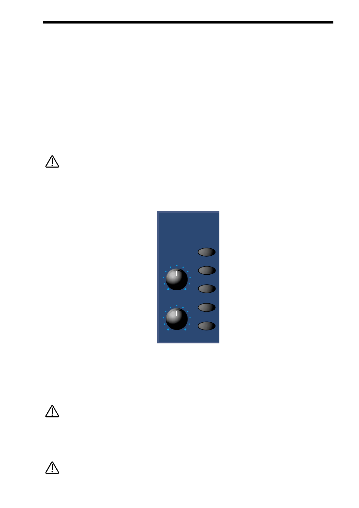
93
Resonance - Knob
This knob controls the amount of Resonance the Filter has. The effect is to emphasise the harmonics around the Cutoff Frequency
( Set by the Frequency knob detailed above). For this reason, on some synths this control is known as Emphasis. Fully anticlockwise, there is no boosting of the Cutoff Frequency, but as you turn the knob clockwise, this frequency will be boosted until when
fully clockwise, it goes in to oscillation producing a new pitched element ( similar to feedback on an electric guitar ). Increasing the
Resonance is very good for bringing out modulation ( movement or change ) in the Filter’s Cutoff Frequency, such as in TB303
basslines. The range of this parameter is 000 to 127. This parameter is memorised with a Program.
Overdrive - Knob
This knob determines how much Overdrive is applied to the Filter. This can warm sounds up, giving them a different harmonic content from the standard waveforms. “Warmer” sounds are produced by modelling the “Saturation effect” common in classic Analogue
Filters. Fully anticlockwise, the signal will be unaffected by the Overdrive. When fully clockwise, full drive will be applied. This parameter’s characteristics can be altered by the amount of mix level feed to the Filter. For really overdriven effects, it is recommended
that all the oscillators are used, each set at maximum Mix levels. The range of this parameter is 000 to 127. This parameter is
memorised with a Program.
The characteristics of the Overdrive can be altered quite drastically with the Overdrive curve parameter on page 4 of the Filter
menu.
Filter Modulation Matrix
This is an extremely powerful feature of the Supernova II keyboard. These controls affect the modulation of the Filter. The knobs
on the left are “Destinations”. They can all be modulated by the “Sources” which are the buttons on the right. The amount of modulation applied from any source is determined by the setting of the knobs. This can be either positive modulation ( Turning either or
both of the knobs Clockwise ) or negative modulation. ( Turning either or both of the knobs Anticlockwise )
For example, to adjust the level of Envelope 2 modulation of the the “Freq” setting of the Filter, press the Env 2 button to define the
modulation source. Now adjusting the “Freq” knob will modulate the Frequency setting of the Filter by Envelope 2.
This makes it possible for all modulation sources to affect any one destination in varying amounts and even in different polarities.
The display will change to indicate the parameter that has been selected and display the newly edited value. The Display will stay
like this until another parameter is adjusted, in which case it will change to display the new parameter. To return to the display of
the Program / Performance name and number, press the Program or Performance button.
Only one source and destination can be edited at one time.
FILTER SECTION
NOTE:
NOTE:
modulation
source
lfo 1
lfo 2
freq
reso/width
env 2
env 3
wheel
NOTE:
NOTE:
NOTE:
NOTE:
Page 94

Even though only one source and destination combination can be edited at one time, all available combinations can happen at the
same time.
Possible Combinations and the effects Produced.
The range of all these parameters is -64 to +63. All these parameters are memorised with a Program.
Frequency Mod- Knob
LFO 1 - Button
This combination controls the amount of change to the Filter Cutoff Frequency ( Initially set by the Frequency knob ) by LFO 1.
With the Frequency Mod knob set to the central position there is no change to the Filter Cutoff Frequency. Anticlockwise of centre
there will be an increasing amount of Negative modulation. i.e. The Filter will be closed more by LFO 1. Clockwise of centre the
modulation is Positive. i.e. The Filter will be increasingly opened by LFO 1.
Frequency Mod- Knob
LFO 2 - Button
This combination controls the amount of change to the Filter Cutoff Frequency ( Initially set by the Frequency knob ) by LFO 2.
With the Frequency Mod knob set to the central position there is no change to the Filter Cutoff Frequency. Anticlockwise of centre
there will be an increasing amount of Negative modulation. i.e. The Filter will be closed more by LFO 2. Clockwise of centre the
modulation is Positive. i.e. The Filter will be increasingly opened by LFO 2.
Frequency Mod- Knob
ENV 2 - Button
This combination controls the amount of change to the Filter Cutoff Frequency ( Initially set by the Frequency knob ) by ENV 2.
With the Frequency Mod knob set to the central position there is no change to the Filter Cutoff Frequency. Anticlockwise of centre
there will be an increasing amount of Negative modulation. i.e. The Filter will be closed more by ENV 2. Clockwise of centre the
modulation is Positive. i.e. The Filter will be increasingly opened by ENV 2.
Frequency Mod- Knob
ENV 3 - Button
This combination controls the amount of change to the Filter Cutoff Frequency ( Initially set by the Frequency knob ) by ENV 3.
With the Frequency Mod knob set to the central position there is no change to the Filter Cutoff Frequency. Anticlockwise of centre
there will be an increasing amount of Negative modulation. i.e. The Filter will be closed more by ENV 3. Clockwise of centre the
modulation is Positive. i.e. The Filter will be increasingly opened by ENV 3.
Frequency Mod- Knob
Wheel - Button
This combination controls the amount of change to the Filter Cutoff Frequency ( Initially set by the Frequency knob ) by the Mod
Wheel. With the Frequency Mod knob set to the central position there is no change to the Filter Cutoff Frequency. Anticlockwise of
centre there will be an increasing amount of Negative modulation. i.e. The Filter will be closed more by the Mod Wheel. Clockwise
of centre the modulation is Positive. i.e. The Filter will be increasingly opened by the Mod Wheel.
Resonance/Width - Knob
LFO 1 - Button
This combination controls the amount of change to the Resonance ( Initially set by the Resonance knob ) by LFO 1. With the
Resonance Mod knob set to the central position there is no change to the Resonance. Anticlockwise of centre there will be an
increasing amount of Negative modulation. i.e. The Filter will become less resonant by LFO 1. Clockwise of centre the modulation
is Positive. i.e. The Filter will become more resonant by LFO 1.
When “Special” Filter types are selected (which are all Dual Filters), this parameter no longer modulates the Resonance of the
Filters but the spacing or “Width” between the 2 Filter’s Cutoff frequencies.
94
FILTER SECTION
NOTE:
NOTE:
NOTE:
NOTE:
NOTE:
NOTE:
Page 95

Resonance/Width - Knob
LFO 2 - Button
This combination controls the amount of change to the Resonance ( Initially set by the Resonance knob ) by LFO 2. With the
Resonance Mod knob set to the central position there is no change to the Resonance. Anticlockwise of centre there will be an
increasing amount of Negative modulation. i.e. The Filter will become less resonant by LFO 2. Clockwise of centre the modulation
is Positive. i.e. The Filter will become more resonant by LFO 2.
When “Special” Filter types are selected (which are all Dual Filters), this parameter no longer modulates the Resonance of the
Filters but the spacing or “Width” between the 2 Filter’s Cutoff frequencies.
Resonance/Width - Knob
ENV 2 - Button
This combination controls the amount of change to the Resonance ( Initially set by the Resonance knob ) by ENV 2. With the
Resonance Mod knob set to the central position there is no change to the Resonance. Anticlockwise of centre there will be an
increasing amount of Negative modulation. i.e. The Filter will become less resonant by ENV 2. Clockwise of centre the modulation
is Positive. i.e. The Filter will become more resonant by ENV 2.
When “Special” Filter types are selected (which are all Dual Filters), this parameter no longer modulates the Resonance of the
Filters but the spacing or “Width” between the 2 Filter’s Cutoff frequencies.
Resonance/Width - Knob
ENV 3 - Button
This combination controls the amount of change to the Resonance ( Initially set by the Resonance knob ) by ENV 3. With the
Resonance Mod knob set to the central position there is no change to the Resonance. Anticlockwise of centre there will be an
increasing amount of Negative modulation. i.e. The Filter will become less resonant by ENV 3. Clockwise of centre the modulation
is Positive. i.e. The Filter will become more resonant by ENV 3.
When “Special” Filter types are selected (which are all Dual Filters), this parameter no longer modulates the Resonance of the
Filters but the spacing or “Width” between the 2 Filter’s Cutoff frequencies.
Resonance/Width - Knob
Wheel - Button
This combination controls the amount of change to the Resonance ( Initially set by the Resonance knob ) by the Mod Wheel. With
the Resonance Mod knob set to the central position there is no change to the Resonance. Anticlockwise of centre there will be an
increasing amount of Negative modulation. i.e. The Filter will become less resonant by the Mod Wheel. Clockwise of centre the
modulation is Positive. i.e. The Filter will become more resonant by the Mod Wheel.
When “Special” Filter types are selected (which are all Dual Filters), this parameter no longer modulates the Resonance of the
Filters but the spacing or “Width” between the 2 Filter’s Cutoff frequencies.
95
FILTER SECTION
NOTE:
NOTE:
NOTE:
NOTE:
NOTE:
NOTE:
NOTE:
NOTE:
Page 96
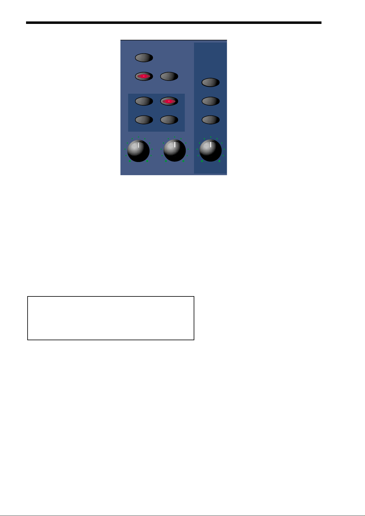
96
LFO SECTION
This section contains all the Knobs and buttons associated with the LFOs. The LFOs ( Low Frequency Oscillators ) produce regular electronic variations which are normally too low a frequency to be heard when converted into audio vibrations. However, when
used to modify various elements of the sound they can be used to create regular changes in pitch ( Vibrato ) or Pulse width and
Filter Modulation ( these create tonal changes in the waveforms ) for example.
Menu - Button
When this button is pressed a series of pages is available on the display containing parameters relevant to the LFO section.
In the LFO section there are 6 pages available. These are selected using the Page Up and Page Down buttons to the left of the
display.
There are a maximum of 2 parameters displayed on any page. One for each line on the display. The upper and lower Data knobs
on the right of the display are used to alter these parameter’s values.
Page 1 looks like so:
The higher parameter is “LFO slew amount”. In this case with a value of 000.
This parameter determines how fast the selected LFO can change to another value ( a bit like portamento ). Use the upper data
knob to adjust this parameters value. In the 000 position ( fully anticlockwise ) no slewing is applied to the selected LFO and the
LFO behaves normally. Turning the upper data knob introduces the slewing effect. The range of this parameter is 000 to 127. This
parameter is memorised with a Program.
The lower parameter is “Env 3 speed mod”. In this case with a value of +63.
This parameter determines how Env 3 effects the speed of the selected LFO. In the central +00 position, there is no change to the
selected LFO’s speed. Anticlockwise of centre, there will be an increasing amount of negative modulation. i.e. the selected LFO will
slow down as the Envelope rises, and speed back up as the envelope falls. Clockwise of centre, there will be an increasing amount
of positive modulation. i.e. the selected LFO will speed up as the Envelope rises, and slow down as the envelope falls. The range
of this parameter is -64 to +63. This parameter is memorised with a Program.
LFO slew amount OOO
Env 3 speed mod +63
LFOs
menu
lfo 1 lfo 2
fast
square
tri
offset delay speed
saw
s/h
normal
slow
Page 97
97
Page 2 looks like so:
The higher parameter is “MWheel speed mod”. In this case with a value of +10.
This parameter determines how the Mod Wheel affects the speed of the selected LFO. If this parameter is set to +00, there is no
change to the selected LFO’s speed. Negative values of this parameter will produce an increasing amount of negative modulation.
i.e. the selected LFO will slow down as the Modulation Wheel is moved forward, and speed back up as it is brought back. Positive
values of this parameter will produce an increasing amount of positive modulation. i.e. the selected LFO will speed up as the
Modulation Wheel is moved forward, and slow down as it is brought back. The range of this parameter is -64 to +63. This parameter is memorised with a Program.
The lower parameter is “AT speed mod”. In this case with a value of +10.
This parameter determines how the Aftertouch affects the speed of the selected LFO. If this parameter is set to +00, there is no
change to the selected LFO’s speed. Negative values of this parameter will produce an increasing amount of negative modulation.
i.e. the selected LFO will slow down as the Aftertouch is applied, and speed back up as it is disengaged. Positive values of this
parameter will produce an increasing amount of positive modulation. i.e. the selected LFO will speed up as the Aftertouch is
applied, and slow down as it is disengaged. The range of this parameter is -64 to +63. This parameter is memorised with a
Program.
Page 3 looks like so:
The higher parameter is “Sync”. In this case with a value of 16th.
This parameter determines where the selected LFO gets its Clock and its resolution. Turning the upper Data knob fully anticlockwise selects the “Off” option which means the selected LFO is running on its own dedicated clock and is not in sync with anything
else. Turning the knob clockwise from this position makes the selected LFO sync to Internal or External MIDI Clock in various signatures ranging from 12 Bars to 32nd Triplets. On the bottom of the display, the number of MIDI clocks for the chosen setting is
displayed, in this case 6 MIDI clocks. The range of this parameter is Off, 32 Triplet, 32nd, 16th Triplet, 16th, 8th Triplet, 16th
Dotted, 8th, 4th Triplet, 8th Dotted, 4th, 2nd Triplet, 4th Dotted, 2nd, 1 Bar Triplet, 2nd Dotted, 1 Bar, 2 Bar Triplet, 1 Bar Dotted, 2
Bars, 4 Bar Triplet, 3 Bars, 5 Bar Triplet, 4 Bars, 3 Bar Dotted ( 4.5 Bars ), 7 Bar Triplet, 5 Bars, 8 Bar Triplet, 6 Bars, 7 Bars, 5 Bar
Dotted ( 7.5 Bars), 8 Bars, 6 Bar Dotted ( 9 Bars ), 7 Bar Dotted ( 10.5 Bars ) & 8 Bar Dotted ( 12 Bars ). This parameter is memorised with a Program.
Page 4 looks like so:
The higher parameter is “LFO delay mode”. In this case with a value of Fade.
This parameter determines how the LFO fade feature operates. When set to Fade, the LFO effect is introduced gradually over the
time period specified by the LFO’s Delay parameter. When set to Gate, the LFOeffect is introduced abruptly after the LFO’s Delay
time has expired. Use the upper data knob to alter this parameter’s value. The range of this parameter is Fade & Gate. This parameter is memorised with a Program.
LFO delay mode Fade
LFO delay fade In
Sync 16th
[6 MIDI clocks]
MWh speed mod +10
AT speed mod +10
LFO SECTION
Page 98

98
LFO SECTION
The lower parameter is “LFO Delay fade”. In this case with a value of In.
This parameter determines how the selected LFO’s Delay parameter behaves. Turning the lower Data knob anticlockwise selects
the “In” option which means if a Delay is set using the LFO Delay Knob, no modulation will be present a the start of the note but
LFO modulation will “Fade in” over the Delay period. Turning the lower Data knob clockwise selects the “Out” option which means
if a Delay is set using the LFO Delay Knob, then LFO modulation will be present a the start of the note and will “Fade out” over the
Delay period. The range of this parameter is In & Out. This parameter is memorised with a Program.
Page 5 looks like so:
The only parameter on this page is “LFO delay sync”. In this case with a value of 16th.
This parameter enables the currently selected LFO’s delay time period to be synchronised to internal or external MIDI clock. Use
the lower data knob to adjust the value of this parameter. When this parameter is set to “Off”, the LFOdelay time is not synchronised to the clock, and the LFO Delay knob on the front panel is used to specify the LFO delay time period. When any other synchronisation rate is selected, the front panel LFO delay knob will have no effect. The range of this parameter is Off, 32 Triplet,
32nd, 16th Triplet, 16th, 8th Triplet, 16th Dotted, 8th, 4th Triplet, 8th Dotted, 4th, 2nd Triplet, 4th Dotted, 2nd, 1 Bar Triplet, 2nd
Dotted, 1 Bar, 2 Bar Triplet, 1 Bar Dotted, 2 Bars, 4 Bar Triplet, 3 Bars, 5 Bar Triplet, 4 Bars, 3 Bar Dotted ( 4.5 Bars ), 7 Bar
Triplet, 5 Bars, 8 Bar Triplet, 6 Bars, 7 Bars, 5 Bar Dotted ( 7.5 Bars), 8 Bars, 6 Bar Dotted ( 9 Bars ), 7 Bar Dotted ( 10.5 Bars ) &
8 Bar Dotted ( 12 Bars ). This parameter is memorised with a Program.
Page 6 looks like so:
The upper parameter is “Delay trigger”. In this case with a value of Multi.
This parameter determines how the "Delay" parameter is triggered on the currently selected LFO. Turning the upper Data knob
anticlockwise selects the "Multi" option. This means the LFO Delay Time is reset to the start value every time any key is pressed.
Turning the upper Data knob clockwise selects the "Single" option. This means the LFO Delay Time is reset to the start value only
if no other keys are currently held down. The range of this parameter is Multi & Single. This parameter is memorised with a program.
The lower parameter is “Triggering”. In this case with a value of Keysync.
This parameter determines how the selected LFO is triggered. Turning the lower Data knob anticlockwise selects the “Freewheel”
option. This means all the LFOs of the “Voices” that are being played are not in phase or in sync. This is the most natural sounding
for vibrato effects etc. Turning the lower Data knob clockwise selects the “Keysync” option. This means all the LFOs of the “Voices”
that are being played are in phase and the cycles of the LFOs are reset to start from the beginning when a new note is struck. The
range of this parameter is Freewheel & Keysync. This parameter is memorised with a Program.
LFO 1 - Button
LFO 2 - Button
The LFO 1 and LFO 2 buttons select which LFO the Offset, Speed & Delay knobs are going to adjust. These buttons also select
which LFO will be edited by most of the parameters within the LFO Menu. To adjust LFO 1 press the LFO 1 button. To adjust the
LFO 2 press the LFO 2 button.
Off set - Knob
The Offset knob controls an “Offset” ( or DC shift ) applied to the LFO waveform. This allows the creation of realistic Stringed
instrument Vibrato effects by making it possible to create vibrato that is only up for example. Fully Anticlockwise, there is no effect
on the normal operation of the LFO. Tuning this knob clockwise of this position introduces an increasing amount of offset applied to
the selected LFO’s waveform until at fully clockwise the LFO’s waveform is only in the upwards direction. The range of this parameter is 000 to 127. This parameter is memorised with a Program.
Delay trigger Multi
Triggering Keysync
LFO delay sync 16th
Page 99

99
Delay - Knob
The Delay knob controls how long after the note is struck before the selected LFO begins to take effect. If the knob is fully anticlockwise, the LFO will begin immediately. As the knob is turned clockwise it will take increasingly longer for the LFO effect to be
introduced.
This is particularly useful for vibrato effects where the LFO if present as the note is struck, can make the note sound out of tune.
By turning the Delay Knob slightly clockwise, the selected LFO will not be introduced until after the note is struck, thereby removing
the problem.
If you have problems getting the selected LFO to take effect, make sure the delay knob is not set fully clockwise.
Fast - Button
Normal- Button
Slow - Button
Speed - Knob
The Fast, Normal & Slow buttons select the frequency range for the currently selected LFO. If the Slow button is selected, the
Speed knob of the selected LFO will have a range that goes from stopped to moderate speeds. If the Normal button is selected,
the Speed knob of the selected LFO will have a range equivalent to that found on a normal synthesizer. If the Fastbutton is selected the Speed knob of the selected LFO will have a range of stopped to several Khz. This parameter is memorised with a Program.
Speed - Knob
The Speed knob controls the rate at which the selected LFO oscillates. Turning the Speed knob fully anticlockwise sets the LFO
running at its slowest speed ( which is actually stopped ). Turning the Speed knob fully clockwise sets the LFO running at its highest speed. ( Which can be KHz )
Square - Button
S a w - Button
Tri - Button
S/H - Button
These Buttons select which waveform the currently selected LFO uses.
The Tri button selects a Trianglewaveform. This waveform gives the smoothest, continuous change in level to the LFO and is
therefore probably the most useful setting. When used in the Oscillator Section, it gives you vibrato ( if used at moderate speed in
subtle amounts ) or “Siren” effects ( if used at slow speeds in large amounts ) or FM type effects ( if used at high speed in subtle
amounts ). If used with the Filter, slow speeds produce Wah Wah effects.
The Saw button selects a Sawtooth waveform. This waveform looks like the teeth of a saw ( from which it gets its name ). This
gives you a falling level which suddenly jumps back up to full level. When used in the Filter, it produces a rhythmic pulsating effect,
similar to a sequenced repeated bass line. When used in the Oscillator Section, it can be used to create “Alarm” type sounds.
The Square button selects a waveform that looks square ( from which it gets its name ). This waveform changes instantly from one
level to another. This is useful for Trill and Computer Game effects.
The S/H button selects the Sample & Hold waveform ( sometimes called Random ). At a regular interval ( governed by the Speed
knob ), the level of the LFO jumps to a new random level and stays there until the next jump. This creates a rhythmic effect particularly if used on the Filter and assigned to the Cutoff Frequency ( refer to the Filter section on page 92 for details ). Useful results
can also be obtained when used in the Oscillator Section in the creation of Computer Game effects. The setting of these buttons
are memorised with a Program.
LFO SECTION
NOTE:
NOTE:
NOTE:
NOTE:
Page 100

100
INPUTS SECTION
Menu - Button
When this button is pressed, there is 1 page available on the display containing parameters relevant to the Inputs section.
There are a maximum of 2 parameters displayed on any page. One for each line on the display. The upper and lower Data knobs
on the right of the display are used to alter these parameter’s values.
Page 1 looks like so:
Inputs 1 & 2 can be monitored, and the sensitivity of the inputs can be adjusted using this page. Peak Program Meters show the
level of both inputs. The levels of each of these signals can be adjusted from +60 dB gain to -8 dB attenuation using the upper and
lower Data knobs. These parameters are memorised with the Global settings.
The setting of these parameters is saved along with all the other Global parameters when the Global parameters are saved while
in the Global menu.
A slight click may be heard at certain intervals as the gain is adjusted. This is due to switching of analogue circuits and is normal.
Constant Gate - Button
When this button is lit, the envelopes are “constantly” gated on as if C3 was being played and held down. This allows signals fed
into the Inputs ( and that are assigned as Special waveforms to the Oscillators ) to be passed through the Nova II keyboard’s synthesis engine without requiring a MIDI Note message to trigger the envelopes. Also, this feature can be used to create sustained
sound effects that require no trigger note. When a Program that has this parameter activated is selected, the Program will sound
straight away as if C3 was played. This will continue until another program is selected. This parameter is memorised with a
Program.
Setting up the Sensitivity/ Input level of the Inputs .
Plug a sound source into one of the Supernova II keyboard's Inputs. Adjust the sensitivity with The Gain Parameter on Page 1 of
the Inputs Menu to the type of sound source connected. As a guideline, in the -4 position the input sensitivity is suitable for accepting signals from Studio equipment such as Samplers, Synths, Workstations, Mixers etc (+4dB). In the +10 position, the sensitivity is
suitable for Consumer Audio Equipment such as Cassette decks etc (-10dB). In the + 25 position, the sensitivity is suitable for guitars etc (-25dB). In the +55 position, the sensitivity is suitable for Microphones etc (-55dB). These settings may vary from equipment to equipment. To set this correctly, press the menu button in the Input section and go to page 1. The display looks like so:
O
O
Inputs
menu
constant
gate
Gain 1 +O
Gain 2 +O
NOTE:
NOTE:
NOTE:
NOTE:
 Loading...