

Page 1

Introduction........................................................... 2
Using this Manual.......................................................... 2
Main Features................................................................ 2
Conventions used in this Manual................................... 2
Quick Start Guide.................................................. 3
Connecting to audio and MIDI equipment...................... 3
Listening to the factory preset sounds........................... 3
Selecting Programs and Drum Maps............................. 3
Selecting Performances................................................. 4
Editing a sound............................................................... 5
Saving a sound............................................................... 6
Editing a Performance.................................................... 7
Saving a Performance.................................................... 8
Listening to the factory demonstration........................... 8
Synthesis Tutorial................................................. 9
Elements of a sound....................................................... 9
Oscillators and waveforms............................................. 9
The Mixer...................................................................... 11
The Filter....................................................................... 11
Envelopes and Amplifier............................................... 12
LFOs............................................................................. 13
Memories...................................................................... 14
Summary....................................................................... 14
MIDI Tutorial......................................................... 15
About MIDI.................................................................... 15
MIDI messages ........................................................... 15
MIDI and Sequencers.................................................. 17
Summary....................................................................... 17
Main Features and Operation............................ 18
Front Panel Layout....................................................... 18
Modes and Menus........................................................ 19
Oscillator Section.......................................................... 22
Mixer Section................................................................ 23
Filter Section................................................................. 24
LFOs Section................................................................ 25
Envelopes Section........................................................ 26
Volume and Keyboard Octave controls........................ 26
Effects / Arpeggiator / Hypersync Section.................... 27
Part Edit Section........................................................... 31
Display and Data Entry Section................................... 32
Mode and Keypad Section........................................... 33
Advanced Features............................................. 34
Oscillator Menu............................................................ 34
Mixer Menu.................................................................. 37
Filter Menu............................................................ .......37
LFOs Menu.................................................................. 38
Envelopes Menu.......................................................... 39
The Effects Menus...................................................... 41
Delay Menu................................................................ 41
Reverb Menu.............................................................. 42
Chorus Menu................................................................43
Distortion Menu............................................................44
EQ Menu..................................................................... 45
Panning Menu............................................................. 46
Vocoder Menu............................................................ 46
Other Menus..................................................................47
Wheels Menu............................................................... 47
Aftertouch and Breath Menu........................................ 48
Utilities Menu................................................................ 49
Global Menu................................................................. 50
Synchronisation Menu.................................................. 52
Arpeggiator Menu......................................................... 53
Part Edit Menu............................................................. 55
MIDI Specification........................................................ 56
MIDI Program Changes and Bank Select.................... 56
Appendix.............................................................. 57
MIDI Implementation Chart........................................... 57
KS 4 / KS 5 Factory Preset Program Listings.............. 58
KS 4 / KS 5 Factory Drum Bank Listings..................... 60
MIDI Controller List....................................................... 61
MIDI NRPN List............................................................ 63
Packed Controller / NRPN Details................................ 64
MIDI System Exclusive................................................. 65
Safety notice, CE and FCC Approvals ........................ 72
Technical Specification.................................................. 73
Index..................................................................... 74
CONTENTS
Contents
• 1 •
Page 2

• 2 •
Thank you for purchasing the Novation KS4 or KS5 Synthesizer. This
instruction manual applies equally to the Four Octave KS4, or Five Octave
KS5 - the only difference being the number of keys.
This instrument is a multi-timbral, enhanced version of the popular KStation keyboard synthesizer. The design of the has evolved from the KStation, using the very latest award-winning Novation technology found in
highly-acclaimed products such as Nova and Supernova II. The KS4 and
KS5 are capable of producing an enormous range of high quality synthesized sounds and are ideal machines for a home studio set-up or for an
experienced producer looking to add an extra dimension of sound power.
Using this Manual
This manual consists of six sections, Introduction, Quick Start Guide,
Synthesis Tutorial, MIDI Tutorial, Main Features and Operation, and
Advanced Features. For easy reference, the section name is printed at
the top of each page. An Appendix on the final pages lists all menu
options and factory preset sounds list.
In order to become an expert user as quickly as possible, it is recommended that this manual is read in sequence chapter by chapter. If sound
synthesis is an unfamiliar subject, then the chapter Synthesis Tutorial
will provide a useful introduction to the techniques used to electronically
simulate the sound of a musical instrument using an analogue music synthesizer.
Another chapter, MIDI Tutorial provides an useful introduction to the sub-
ject of MIDI and how it is used for communication between instruments
and / or sequencers. The chapter also describes how the KS4 / KS5
transmits and recognizes various types of MIDI messages.
If the general principles of Sound Synthesis and MIDI are already familiar,
then the Quick Start Guide is the place to begin. Once familiar with the
main features of the machine, the Advanced Features section covers the
Effects, Arpeggiators, Synchronization, Triggering and the Utilities, and
will provide all of the information needed to operate the KS4 / KS5 in the
most creative, productive way. Have fun !
Main Features
Four hundred Program memories
Two hundred factory programmed sounds are included and a further two
hundred user sound memory locations are provided (factory programmed
sounds may be overwritten).
One hundred Performance memories
Fifty factory programmed multi-timbral Performances are included and a
further fifty user Performance locations are provided (factory programmed
Performances may be overwitten).
Each Performance can consist of up to four different Programs, each with
its own unique effects settings, MIDI channel assignments and keyboard
settings. Program data for each Performance Part are stored in the
Performance memory location.
Four Drum Maps
Two factory programmed Drum Maps are included with a further two user
Drum Maps available (factory programmed Drum Maps may be over-written).
Drum Maps allow a whole drum kit to be mapped across 49 notes of the
keyboard with each drum sound available on a different key. Drum Maps
consume only one unit of Multi-timbrality.
Powerful Oscillators
Three Oscillators provide the standard Sawtooth, Square, Variable Pulse,
Triangle and Sine waves. Additional sampled waveforms are also available, each containing complex audio information not available in the standard waveforms.
The Sawtooth, Triangle and Sine waveforms may be duplicated within a
single Oscillator to provide thicker sounding waveforms. Synchronization
and FM between two Oscillators allow the generation of metallic or percussive timbres. A four section noise source completes the waveform
engine.
External Audio Input
The Mixer allows an external audio signal to be combined with the
Oscillators and processed through the Filter, Envelopes and Effects.
Envelopes may also be auto-triggered by an external signal.
Vocoder
The 16 band Vocoder makes it easy to create Robot and Talky sound
effects.
Four Arpeggiators
The arpeggiator features six different operational modes with adjustable
gate time for staccato effects. Thirty two rhythmic patterns are available to
introduce complex motion effects. In multi-timbral Performance Mode, up
to four arpeggiators are available simultaneously, each with their own
unique settings. All four arpeggiators can can be individually synchronised
to MIDI Clock at different time signatures.
HyperSync
Sixteen ‘Hypersync’ templates provide fast,effective, musically synchronized settings with a simple twist of a control.
When selected, synchronisation settings to four Effects and four Program
parameters are instantly applied. Settings for the Delay level, Chorus
Level, Panning Depth and EQ Modulation Depth are also applied.
Using these tempo synchronized features can significantly enhance music
production.
Comprehensive MIDI Control Specification
Adjustments of any controls transmit MIDI Controller numbers or NRPNs
for real time recording by a sequencer or computer.
Powerful Effects
The effects processor includes Distortion, Stereo Chorus, Phaser, Reverb,
Synchronized Delay and Synchronized Stereo Panning. Complex, dynamic timbres may be created using tempo synchronized effects settings. A
final output EQ and Filter section complete with a tempo synchronized
LFO allow for a performance to be automatically filtered and time locked
from 32nd triplets through to several bars.
In multi-timbral Performance Mode, each of the four individual Parts can
have its own unique Effects settings.
Data Compatibility
The KS4 and KS5 have been designed to allow the loading of Sysex data
dumps from the Novation K-Station and A-Station. This ensures that existing sound libraries and global settings can easily be transferred from the
older types of machine. Data is also fully compatible with the KS Rack.
Conventions Used In This Manual
The word ‘Program’ refers to a collection of knob and switch settings that
define an individual ‘Sound’. These settings are then saved as a
‘Program’ which has a corresponding name and number in the machine’s
non volatile memory.
Throughout this manual the two words, ‘Sound’ and ‘Program’ are frequently referred to and essentially have the same meaning.
The term ‘Drum Map’ refers to a whole kit of drum sounds which are
mapped across the keyboard, with each keyboard note triggering a different drum sound.
The word ‘Performance’ refers to a multi-timbral setting where up to four
Programs and/or Drum Maps are available for playing simultaneously.
This entire arrangement is then saved as a ‘Performance’ which has a
name and number assigned in the machine’s non-volatile memory.
Each of the four Programs / Drum Maps making up a Performance is
referred to as a ‘Part’.
The word ‘Preset’ refers to a Program/Performance/Drum Map which was
set up at the factory to showcase some of the KS4 / KS5’s powerful
sound possibilities. Preset memories may actually be overwritten with new
settings, but it is possible to restore them to the original factory set
Programs, Drum Maps or Performances by loading in a MIDI file if they
have been overwritten by mistake.
INTRODUCTION
Using this Manual - Main Features - Conventions used in this manual
Page 3
• 3 •
Text in CAPITALS refer to a front panel control or legend (even though the
name of the control may actually be in lower case on the front panel). It
could be a knob or button. For example, FREQUENCY refers to the Filter
frequency control knob. MENUS refers to the Menu Mode button.
The fastest way to become familiar with the product is to follow this quick
start guide. It covers connecting up to audio equipment, listening to the
factory preset sounds, selecting sounds, editing a sound and saving a
sound into a memory location.
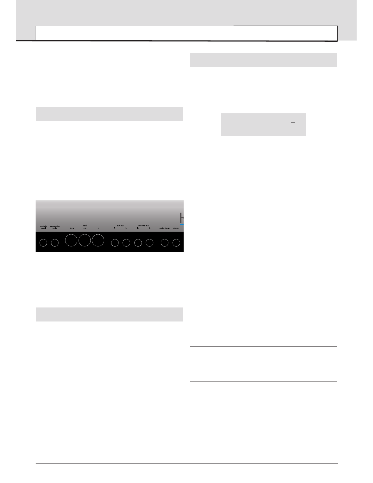
Connecting to Audio and MIDI equipment
Before connecting to other units in the system, ensure the power to all
units is off. Connect an audio cable from the Left and Right master output
sockets to a suitable amplifier or mixing desk stereo inputs. If MONO
operation is required, either output may be used.
Connect the power cable to the socket ‘Power In’ and connect the cable
to the AC mains. Switch on the power. The display will show the name of
the last selected Program, Drum Map or Performance and its number.
Select Program Mode by pressing the PROG button.
Finally, switch on the other units in the Audio system (amplifier, mixer
etc.).
Although the KS4 / KS5 has its own keyboard which would normally be
used to trigger the internal sounds, it is still possible to play the internal
sound engine by connecting an external master keyboard.
Listening to the factory preset sounds
Set the VOLUME control to a reasonably high output level. This will maintain a good signal to noise ratio. Make sure that the input volume setting
on the system amplifier or mixer is initially set to zero.
On leaving the factory, the KS4 / KS5 is set to receive MIDI information on
Channel 1, so, if using an external master keyboard or sequencer to trigger the sounds, ensure that it is set to transmit on this MIDI channel.
Playing its own keyboard, an master keyboard or sequencer will result in
the currently selected factory preset sound being heard.
A full listing of the factory preset Programs, Drum Maps and
Performances can be found on page 59. The first few locations of the
user Programs in bank 3 (Program Number 300 onwards) contain initialisation examples. These are also described in the list.
Selecting Programs and Drum Maps
There are two main modes of operation - Program Mode where the
machine is mono-timbral (only one type of sound is available for playing)
and Performance Mode where the machine is four Part multi-timbral (up
to four different sounds can be played simultaneously).
Program Mode is selected by pressing the PROG button. The LED above
the button lights to confirm that Program Mode is selected. The standard
Program Mode display will be shown.
Program’s name 1
01
Category Name
Program Mode is convenient for auditioning individual sounds.
Standard Programs are organised into four banks, each bank containing
100 sounds. These are referred to as banks 1, 2, 3 and 4.
Bank 1 100 - 199 - First bank of factory preset sounds
Bank 2 200 - 299 - Second bank of factory preset sounds
Bank 3 300 - 399 - First bank of user sounds
Bank 4 400 - 499 - Second bank of user sounds
The next four banks contain four Drum Maps. Drum Maps are whole kits
of percussion sounds, each sound corresponding to an individual note on
the keyboard. A Drum Map is a ‘batch’ of 49 Programs. Each of these
sounds has been programmed to closely immitate the sound of a real or
electronic type of percussion sound, be it a Bass Drum, Snare Drum etc.
Following the 49th Drum Map Program is an extra Program containing the
Effects settings used by the Drum Map as a whole.
A Drum Map may be selected at any time by pressing the DRUM EDIT
button. The last selected drum bank will then be available on the keyboard to audition.
When any Program in a Drum Map is selected, all other Programs located
in the same Drum Map are also available for playing on the keyboard.
To return to a normal Program, select a program between 100 and 499
The Drum Maps available are :
Bank 5 500 - 549 - First factory preset Drum Map
Bank 6 600 - 649 - Second factory preset Drum Map
Bank 7 700 - 749 - First user Drum Map
Bank 8 800 - 849 - Second user Drum Map
There are four methods of selecting Programs, Drum Maps or
Performances. Before using any of the methods, Ensure that a Menu is
not active (the LED above the MENUS button must not be lit). If a Menu
is selected, press the PROG button to select Program Mode.
1 - Using the 0 - 9 Keypad buttons
There must always be a three digit entry on the numeric keypad, for
example : To select Bank 1 sound 8, press the 1, 0 and 8 buttons. The
display will now show the name of the newly selected sound and indicate
that sound 108 has been selected.
2 - Using the PAGE buttons
The PAGE buttons may be used to move up or down to the next Program.
Pressing and holding either button for a short period will cause the
Program / Performance number to advance / decrease by a further 9.
3 - Using the PERF / PROG / DATA knob
The DATA knob may be used to move up or down to the next Program.
Turning the knob slowly will advance the selection by one by one. Turning
the knob more quickly will increase the rate of selection.
If the the end of a Program bank has been reached, the first Program of
the next bank will be selected, for example Program 199 moves to
Program 200.
QUICK START GUIDE
Connecting audio equipment - Listening to preset sounds - Selecting Programs
Page 4
• 4 •
Each Program is assigned to a category. Categories are used to classify a
Program that belongs to a sound group such as Bass sounds, String
sounds, Lead sounds etc.
It is possible to use the DATA knob to search for sounds within a specific
category. This is a convenient way of audioning all sounds that belong to
a specific category.
To search for a Program within a category, press the BY CATEGORY button. The LED above the button is lit while category searching is enabled.
Program’s name 101
Bass
Using the DATA knob selects the next Program assigned to the same category. In the above example the next Bass type of Program will be selected.
When category searching is enabled, the default category is whatever category was assigned to the Program when it was originally saved (see
Page 6). To search under a different category, use the SELECT left and
right buttons.
After pressing one of the SELECT buttons, a new category is displayed
Program’s name 101
Strings
The first Strings Program will not be located until the DATA knob is used
to search for the first Strings Program. If no Programs exist using the current category, ‘NO PROGRAMS’ will be displayed as the Program’s name,
but the previously selected Program will still be available.
Category searching is cancelled by pressing the BY CATEGORY button
again, whereby the LED above it will extinguish.
4 - Using MIDI Program Change commands
A MIDI Program change message sent from an external sequencer or
controller keyboard will select the appropriate Program or Performance
within the currently selected bank.
A MIDI Bank Change message (CC32) received along with a Program
change message will select the appropriate Program or Performance within the bank specifed by the Bank Change message.
If Bank Change messages are used, it is recommended that the Bank
Change message is sent immediately before the Program Change message. In Program Mode, A Bank Change value of 1 is used to select
Bank 1, a value of 2 is used to select Bank 2 etc.
A full table of the bank values used is found on page 56 along with details
on how they should be used.
Whenever a new Program or Performance is selected from front panel,
both Bank Change and Program Change are transmitted via MIDI Out. It
is sometimes convenient to record these messages into a sequencer in
real-time.
Selecting Performances
Performances are multi-timbral arrangements where up to four seperate
Programs or Drum Maps are available for playing simultaneously.
A bank of 100 Performances is available. The first 50 performances have
been preset at the factory and showcase the various layering, keyboard
splits and multi-timbral arrangements available. The remaining 50 performances are blank user locations.
Performance Mode is selected by pressing the PERF button. The LED
above the PERF button lights to confirm selection. The standard
Performance Mode screen is displayed.
Performance name 1
01
123 234 345 456
The cursor is positioned at the Performance number adjacent to the
Performance’s name. (Performances are numbered 100 to 199). At this
position, selection of Performances is achieved in a similar manner to
selecting Programs by means of the Keypad buttons, the PAGE buttons,
or the DATA knob.
The BY
CATEGORY button cannot be used to select Performances.
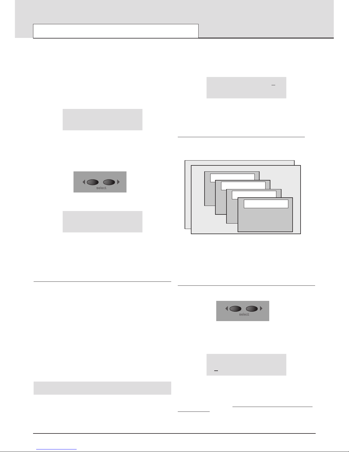
The four sets of numbers beneath the Performance name refer to the
Program numbers that are allocated to each of the parts within the
Performance. The illustration below shows the relationship between
Performances, Parts and Programs.
Up to 100 Performances may be saved in the KS4 / KS5. The first 2 are
shown in the above illustration - Number 100 and 101. Held in the
Performance are up to 4 part ‘slots’ that may have any one of the 400 single Programs selected for each one. For versatility, other information such
as MIDI channel, note range etc. is also held in each part along with the
program number.
Selecting / Changing the Programs on a Part in a Performance
The SELECT left and right buttons are use to select the Part where the
Program is held. Once selected it may be changed or edited.
Press the SELECT left button. The cursor will move to the Program number assigned to Part 1 of the Performance. Subsequent presses of the
SELECT left and right buttons will move to the next Program number
across the bottom line of the display.
Performance name 101
123 234 345 456
The KEYPAD buttons, PAGE up / down buttons and DATA knob may also
be used to select a new Program number on the selected Part.
The BY CATEGORY button may be used to select a Program in the same
way as previously described. T
o return to selecting a Performance, press
the PERF
button.
Any changes made are temporary until the Performance is written into
memory.Using and Editing Performances is covered in more detail on
page 7.
QUICK START GUIDE
Selecting Programs - Selecting Performances
Electric Drums 600
Strings 345
Electric Piano 234
PERFORMANCE 100
PERFORMANCE 101
Bass Guitar 123
Part 1
MIDI Channel 1
Outputs 1 & 2
Volume 99
Semitone offset +12
Cents offset -06
Part 2
Part 3
Part 4
Page 5
Editing a Single Program (sound)
Editing Programs
Once familiar with the sounds that are available, select Program Mode
(selected by pressing the PROG button), to select Program number 499.
This is a very basic synthesizer sound which can be used as a starting
point to create a new, more interesting sound for your own use.
When this sound is played from the keyboard, it will be noticed that the
volume of the sound instantly reaches its maximum level when a key is
pressed, and dies away instantaneously as soon as the key is released.
The most useful editing controls on the KS4 / KS5 are found on the front
panel and some of these will be now be used to modify (edit) this basic
program.
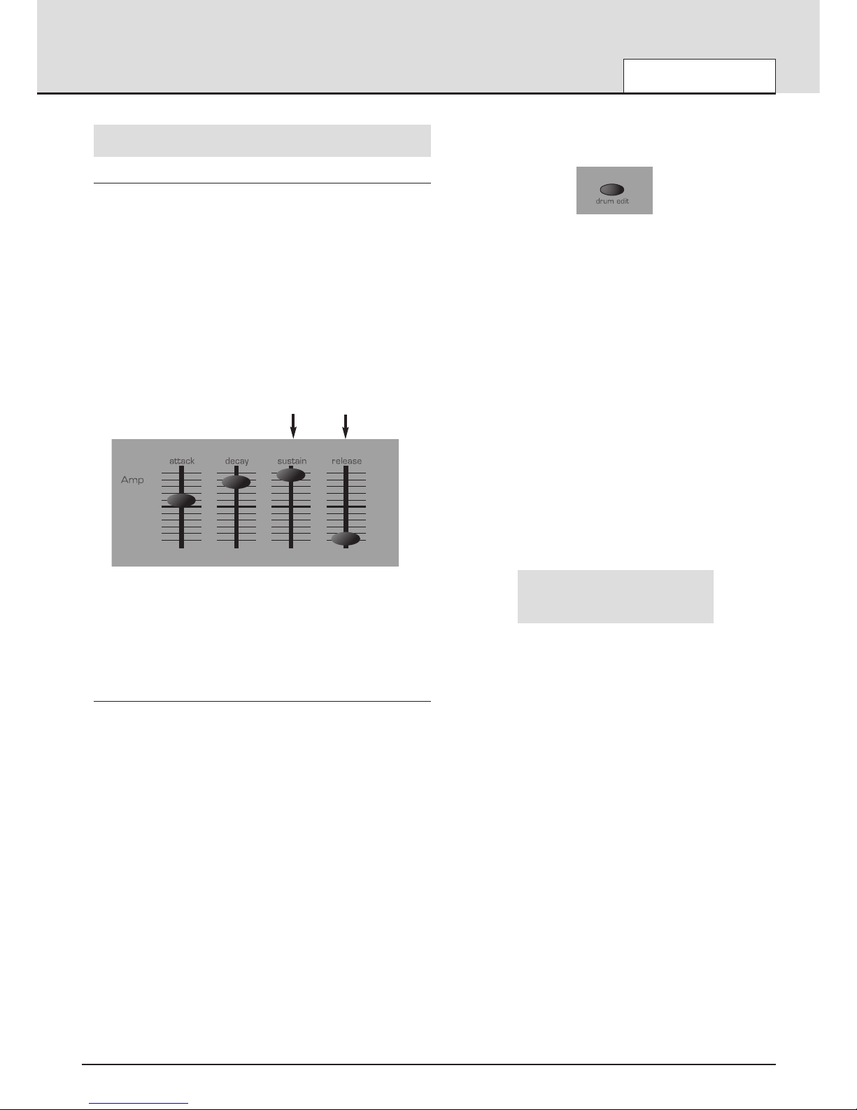
While playing the keyboard, adjust the Amplifier Envelope SUSTAIN control. Notice how that the sound level when holding a key down changes.
Set this control to just over half. Now adjust the RELEASE control. Notice
how, when a key on the keyboard is released the sound will now gradually
die away.
How quickly the sound dies away depends on the setting of this control.
The sound is still a little too bright. Adjust the FREQUENCY control in the
filter area. Notice how the sound becomes softer as the control is rotated
anticlockwise. Continue to make adjustments until a desired sound is
heard. The first small edit is now complete!
The edited Program must now be saved into a memory location if it is to
be needed for the future.
Editing Drum Maps
Editing Drum Maps sounds is similar to editing Standard Programs. It is
sometimes convenient to think of Drum Maps as whole batch of special
Programs (the four Drum Maps available are numbered as Program
Banks 5, 6, 7, & 8). However, there are some important differences to
bear in mind when editing Drum Maps.
1) Whenever a sound is selected from a Drum Map, all other sounds
located within the same Drum Map are immediately available for playing
on the keyboard. Each keyboard note triggers a different percussion
sound within the same Drum Map.
The keyboard notes used to trigger a sound depend on the Program’s
program number within the Drum Map. For example, Drum Map Program
500 is always triggered by the lowest note, (C) Drum Map program 501 by
the next note upwards and so on.
Note : If using a KS5 - When a Drum Map is selected, the range of Drum
sounds available on the keyboard only covers four octaves (49 notes).
2) It is the sound selected within the Drum Map which determines which
sound within the Drum Map is available for editing on the front panel. Only
one Drum Map Program can be edited at a given time. See the following
paragraphs.
3) In a Drum Map, there is only one set of Effects available. All sounds in
the Drum Map share the same single set of Effects settings. Therefore,
altering any Effect while a Drum Map sound is selected will simultaneous-
ly affect all other sounds within the same Drum Map. To edit a Drum Map
sound, press the DRUM EDIT button.
The Drum bank previsouly selected (bank 500 when shipped from the factory) will now be available to play across the keyboard.
To edit a specific sound in the Drum Map, hold down the DRUM EDIT button and press the key that corresponds to the sound to be edited.
It is only possible to select a single Drum sound in a Drum Map for editing
at any one time. If another Drum Program is selected before the previously selected one is written to memory, any edits previously made will be
immediately lost.
Once a drum sound has been selected, it can be edited in the same way
as a standard Program. This flexibility means that a great many new
Drum or Precussion type sounds may easliy be created.
Any edits made will only become apparrent when the currently selected
Drum Program is triggered from the keyboard. All other drum sounds will
remain unaffected. The exception is a change to any Effects settings
(Chorus, Delay, Pan etc). These are applied to all sounds within the Drum
Map.
When the standard Program Mode display is shown (available at any time
by pressing the PROG button), an asterisk before the Program’s location
number indicates whether the Program / Drum Map has been edited in
some way. For example :
Program’s name *101
Drums
QUICK START GUIDE
Editing a sound
• 5 •
SUSTAIN control
RELEASE control
Page 6

Saving a sound
Single sounds (standard Programs or Drum Map Programs) may be
saved in any memory location from 100 to 849.
It is recommended that the user locations are used early on for saving
new sound creations. These are Banks 3 & 4 (locations 300 to 499) for
standard Programs or Banks 7 & 8 (locations 700 to 899) for Drum Map
Programs.
The factory preset sounds in Banks 1, 2, 5 and 6 may also be overwritten
if desired. Once these factory presets are overwritten, they may only be
retrieved by loading in a Sysex dump. (See page 49 for saving a sysex
backup of the factory preset or user programs onto an external MIDI
sequencer).
It is possible to write a standard Program to a location within a Drum Map
or to write a Drum Map Program to a location within a standard Program
bank.
When a standard Program is imported into a Drum Map, the Program will
only be available by playing a single key on the keyboard (determined by
the destination Program number within the Drum Map). Effects settings of
the original Program are not copied across.
If a Drum Map Program is written to a standard Program location, the
drum sound in question will now be available for playing across the entire
keyboard. (the audible results however may not be that satisfying). Effects
settings of the original Drum Map are copied across.
NOTE: When shipped from the factory, the global memory protect switch
is set to on. The memory protect switch is a safety feature designed to
prevent memories from being overwritten by accident. In order to save a
sound, the global memory protect must be switched off.
If an attempt is made to save to a memory while the global memory protect is still switched on, a brief warning message will be displayed.
Memory Protect On !
No data will have been written to memory.
Switching off Global Memory Protect
Press the MENUS button. The LED above the MENUS button will now
light, indicating that Menu Mode is selected. Select the Global Menu by
pressing the ‘0’ button on the 0 - 9 numeric keypad. If necessary, use the
PAGE buttons (immediately to the left of the display window) to scroll up
and down the pages within the menu until the display shows Mem
Protect and its current setting (ON or OFF). Use the DATA knob to turn
memory protect OFF.
Exit Menu Mode either by pressing the MENUS button again or by pressing the PROG button. (the LED above the MENUS button extinguishes,
indicating that Menu Mode is no longer active).
To save a Program to a memory location
Press the WRITE button.
Write Program to
DestProgName 499
The display will now show the destination memory number where the
Program is about to be saved to. In this example, Write to 499. Notice
that the destination memory is always initially set to the currently selected
Program’s number.
It is possible to save a Program to a different memory location. Use the
PERF / PROG / DATA knob or Keypad buttons to select a different destination memory if required. Any location within the Standard Program
banks or Drum Maps can be selected.
Shown on the bottom line of the display is the name of the Program currently located in the destination memory.
Press the WRITE button again.
Name Program
‘DestProgName’
On this display it is possible to edit the Program’s name. Use the Left and
Right SELECT buttons to move the cursor within the Program’s name
text. Use the PERF / PROG / DATA knob to edit the character located at
the cursor.
Press the WRITE button again.
Set Program Category
Bass
On this display, the category of the Program can be set. Setting a category allows the category search feature (see pages 4 & 32) to easily find
specific types of sounds easily. There are 17 different categories available.
To complete the saving procedure, press the WRITE button again (display
flashes PROGRAM SAVED). This saves the edited Program to memory
and once the sound has been written Program Mode will be selected.
At any point in the saving procedure, the COMPARE button can be used
to audition the Program located at the destination memory. This feature
can be useful in helping to avoid over-writing a Program memory containing wanted data.
While the COMPARE button is held, the currently edited Program buffer is
replaced with the Program located at the saving destination memory. This
destination Program can be played from the keyboard. As soon as the
COMPARE button is released, the Program buffer is restored complete
with any edits previously made.
QUICK START GUIDE
Saving a sound
• 6 •
Categories
No. Description
0Bass
1 Arpeggio
2Motion
3 Dance
4Pad
5 EP/Clav
6 Strings
7Brass
8 Organ
9 Sweeps
10 Soft Lead
11 Hard Lead
12 Bells
13 SFX
14 Vocoder
15 Ex Aud Trig
16 Drums
Page 7

Editing a Performance
Performance Mode is equivalent to using four KS 4 / KS 5 machines,
each playing in Program Mode. Performance Mode enables the machine
to be used multi-timbrally. Up to four different Parts (slots that contain programs) can be used and played simultaneously. Performances can be
configured in a number of different, interesting ways.
Performance Mode is selected by pressing the PERF button. The LED
above the PERF button lights to confirm selection. The standard
Performance Mode screen is displayed.
Performance name 1
01
123 234 345 456
The cursor is positioned at the Performance number adjacent to the
Performance’s name. (Performances are numbered 100 to 199). At this
position, selection of Performances is achieved in a similar manner to
selecting Programs by means of the Keypad buttons, the PAGE buttons,
or the DATA knob.
Editing Parts
To edit a single part in the performance, press the Part EDIT button corresponding to the Part (that contains the Program) to be edited or press the
SELECT left and right buttons until the cursor is beneath Program number
to be edited. The LED above the Part’s EDIT button lights.
At all times, one of these EDIT buttons will be selected. When the MIDI
channel is different on each Part (In multi-timbral configuration), the EDIT
buttons determine which Part(s) will be heard when the keyboard is
played.
The bottom row of buttons indicate which of the four Parts is used by the
Performance. Any combination of the four available Parts is possible. A
green LED above the button indicates whether the Part is ‘active’ (used by
the Performance).
When a Performance is written to a memory location, the status of these
eight buttons are stored.
Part Layering
Two or more Parts may be played simultaneously on the keyboard.
Layering Parts enables even richer sound textures to be easily created.
To create a layer, Press the MENU button under the Part Level knob. Use
the PERF/PROG/PAGE up or down keys to select the MIDI channel page
in the Menu. Use the PERF/PROG/DATA to set the MIDI channel to the
same number for each part used for the layer.
While Parts are layered together, it is possible to dynamically switch
between them while playing, determining which Part(s) are heard by using
the keyboard’s note velocity (ie how hard the keyboard note was played).
Velocity cross fades are possible. See page 55 for more details on this.
Keyboard Splits
Each Part may have its own area of the keyboard assigned to it. It is possible to assign the whole keyboard range to a part, just a single note or
any range in between. The keyboard ranges of different Parts are allowed
to overlap by any amount, so many interesting arrangements are possible.
To create a split, Press the MENU button under the PART LEVEL knob.
Use the PERF/PROG/PAGE up or down keys to select the PART Low
Note or PART High Note page.in the Menu. Use the PERF/PROG/DATA
to set the high or low note. While in each part Menu ensure the MIDI
channel is set to the same number.
When Keyboard-split Parts share the same MIDI channel, they can all be
accessed at once by playing the keyboard.
Multi-timbral
The term multi-timbral means ‘more than one sound type’. It is possible to
configure the machine such that ‘more than one sound type’ can be
played at the same time.
In this configuration, each Part has its own unique MIDI channel setting.
This is the ideal arrangement for use with an external sequencer, where
each Part can be controlled and played individually.
To create a multi-timbral configuration, it is only necessary to have a different Program (sound) allocated to each of the parts and for it to have a
different MIDI channel number.
Combinations of the above arrangements are also possible. For example,
it is possible to have two Parts layered together, while another Part is
assigned to different area of the keyboard and a fourth Part is set to use a
different MIDI channel altogether.
The Part Edit section on the front panel is used to determine which Part(s)
are used by the Performance and which Part(s) can be edited using the
front panel controls.
QUICK START GUIDE
Editing a Performance
• 7 •
Page 8

Saving a Performance
Once a Performance has been edited, it must be saved into a
Performance memory if it is be recalled for future use.
Saved along with the Performance data are the complete Program data
contained in each of the four Performance Parts. When a Performance is
saved, the original versions of the Part Programs in the Program
Mode memory locations are NOT over-written.
If a Part contains a Drum Map, only the effects settings for that Drum Map
are saved in the Performance.
Performances may be saved in any Performance memory location from
100 to 199. It is recommended that the user locations are used early on
for saving newly created Performances. These are locations 150 to 199.
The factory preset Performances in locations 100 to 149 may be overwritten if desired. Once these factory presets are overwritten, they may only
be retrieved by loading in a Sysex dump. (See Page 49 for saving a
sysex backup of the Performances to an external MIDI sequencer).
NOTE: When shipped from the factory, the global memory protect switch
is set to on. The memory protect switch is a safety feature designed to
prevent memories from being overwritten by accident. Therefore, in order
to save a Performance, the global memory protect must be switched off.
See page 6 for details on how to do this.
If an attempt is made to save to a memory while the global memory protect is still switched on, a brief warning message will be displayed.
Memory Protect On !
No data will have been written to memory.
To save a Performance to a memory location
Press the WRITE button.
Write Performance to
DestPerfName 199
The display will show the destination memory number where the
Performance is about to be saved to. In this example, Write to 199.
Notice that the destination memory is always initially set to the currently
selected Performance’s number. It is possible to save a Performance to a
different memory location. Use the PERF / PROG / DATA knob or Keypad
buttons to select a different destination memory if required.
Shown on the bottom line of the display is the name of the Performance
currently located in the destination memory.
Press the WRITE button again.
Name Performance
‘DestPerfName’
On this display it is possible to edit the Performance’s name. Use the
SELECT Left and Right buttons to move the cursor within the
Performance’s name text. Use the DATA knob to edit the character located at the cursor.
To complete the saving procedure, press the WRITE button again. This
saves the edited Performance to memory (display flashes PERFORMANCE SAVED) and once it has been written, Performance Mode will
be selected
To save (Export) an individual Program on a Part in a Performance
back to an ordinary Program
In Performance Mode it is possible to save (export) any of the Programs
contained within the Performance’s four Parts back to an ordinary
Program bank memory location from 100 to 849.
One of the outstanding features of the KS4 / KS5 is that a complete new
set of programs are held in each part in performance mode IN ADDITION
TO THOSE HELD IN THE SINGLE PROGRAM MEMORIES 100 - 849.
Therefore any modifications of programs held in a part in a performance
WILL NOT alter any of the programs in the normal single program memories 100 - 849.
When tweaking a performance it is useful to be able to export a program
out of a performance back to a single memory location. This can then be
used in another performance if necessary.
Select Performance Mode by pressing the PERF button.
Performance name 1
01
123 234 345 456
Press the WRITE button to start the saving procedure.
Write Performance to
DestPerfName 101
Press the EDIT button in the Parts section that corresponds to the part
that the program is to be exported from. In this example the desired program is being used on Part 2, so press the Part 2 EDIT button. The display changes to :
Export PART to Prog
This Program 234
The program destination ( 234 in this example ) can kept or changed
using the DATA knob, PAGE UP/DOWN buttons or 0 - 9 keypad.
A press of the write button then prompts for a new program name to be
entered if required.
A further press of the write key prompts for a category and a final press
saves the exported program.
Listening to the factory demonstration
To complete this Quick Start Guide section, some time spent listening to
the sounds that the KS4 / KS5 is capable of producing will be of benefit
when it comes to creating new sounds.
Press the MENUS button - the LED above the button will light. Now simultaneously press the both the keypad 1(osc’s) and 2(filter) buttons. The
Factory demonstration will begin to play. Once the demonstration has finished, the previously selected mode will be active.
It is possible to stop the demonstration at any time while it is playing by
pressing the PROG or PERF button to return immediately to Program
Mode or Performance Mode.
QUICK START GUIDE
Saving a Performance - Listening to the factory demonstration
• 8 •
Page 9
It is recommended that this chapter is read carefully if Analogue sound
synthesis is an unfamiliar subject. Users familiar with this subject can skip
this chapter and move on to the chapter - MIDI Tutorial on Page 15.
Elements of a sound
To gain an understanding of how a Synthesizer generates sound it is
helpful to have an understanding of the components that make up a
sound, be it musical or non musical.
The only way that a sound may be detected is by air vibrating the
eardrum in a regular, periodic manner. The brain interprets these vibrations (very accurately) into one of an infinite number of different types of
sound.
Remarkably, any sound may be described by just three terms, and all
sounds always* have them. They are :
* Volume
* Pitch
* Tone
What makes one sound different to another is the proportion of these
three qualities initially present in the sound and how these three terms
change throughout the duration of the sound.
With a musical synthesizer, we deliberately set out to have precise control
over these three terms and, in particular, how they can be changed
throughout the duration of the sound. These terms are often given different names, Volume is referred to as Amplitude, Pitch as Frequency and
Tone as Timbre.
Pitch
Taking the example of air vibrating the ear drum, the pitch is determined
by how fast the vibrations are. For an adult human, the lowest vibration
perceived as sound is about twenty times a second, which the brain interprets as a bass type sound, and the highest is many thousands of times a
second, which the brain interprets as an extreme treble type sound.
If the number of peaks in the two waveforms (vibrations) are counted, it
will be seen that there are exactly twice as many peaks in Wave B as in
Wave A. (Wave B is actually an octave higher in pitch than Wave A). It is
the number of vibrations in a given period that determines the pitch of a
sound. This is the reason that pitch is sometimes referred to as frequency.
It is the frequency of the waveform peaks which are counted during a
given period of time.
Tone
Musical sounds consist of several different related pitches occurring
simultaneously. The loudest is referred to as the ‘Fundamental’ pitch and
corresponds to the perceived note of the sound. Pitches related to the
fundamental are called harmonics. The relative loudness of these harmonics compared to the loudness of all the other harmonics (including the
fundamental) determines the tone or ‘Timbre’ of the sound.
Consider two instruments such as a harpsichord and a piano playing the
same note on the keyboard and at equal volume. Despite having the
same volume and pitch, the instruments would still sound distinctly different. This is because the harmonics present in a piano sound are different
to those found in a harpsichord sound.
Volume
Volume, which is referred to as the amplitude or loudness of the sound is
determined by how large the vibrations are. Very simply, listening to a
piano from a metre away would sound louder than if it were fifty metres
away.
Having shown that just three elements make up any sound, these elements now have to be related to a Musical synthesizer. It is logical that a
different section of the Synthesizer ‘Synthesizes’ (or creates) these different elements.
One section of the synthesizer, the Oscillators provide raw waveforms
which provide the pitch of the sound along with its raw harmonic content
(tone). These signals are then mixed together into a section called the
Mixer and the mixed oscillator signal is then fed into a section named the
Filter which is responsible for further altering the tone of the sound. It
does this by removing (filtering) certain undesired harmonic frequencies.
Lastly, the filtered signal is fed into a final section, the Amplifier which
determines the final volume of the sound.
Additional synthesizer sections; LFOs and Envelopes provide ways of
altering the pitch, tone and volume of a sound by interacting with the
Oscillators, Filter and Amplifier, providing changes in the character of
the sound which can evolve over time. Because LFOs and Envelopes
only purpose is to control (modulate) the other synthesizer sections, they
are commonly known as ‘modulators’.
These various synthesizer sections will now be covered in more detail.
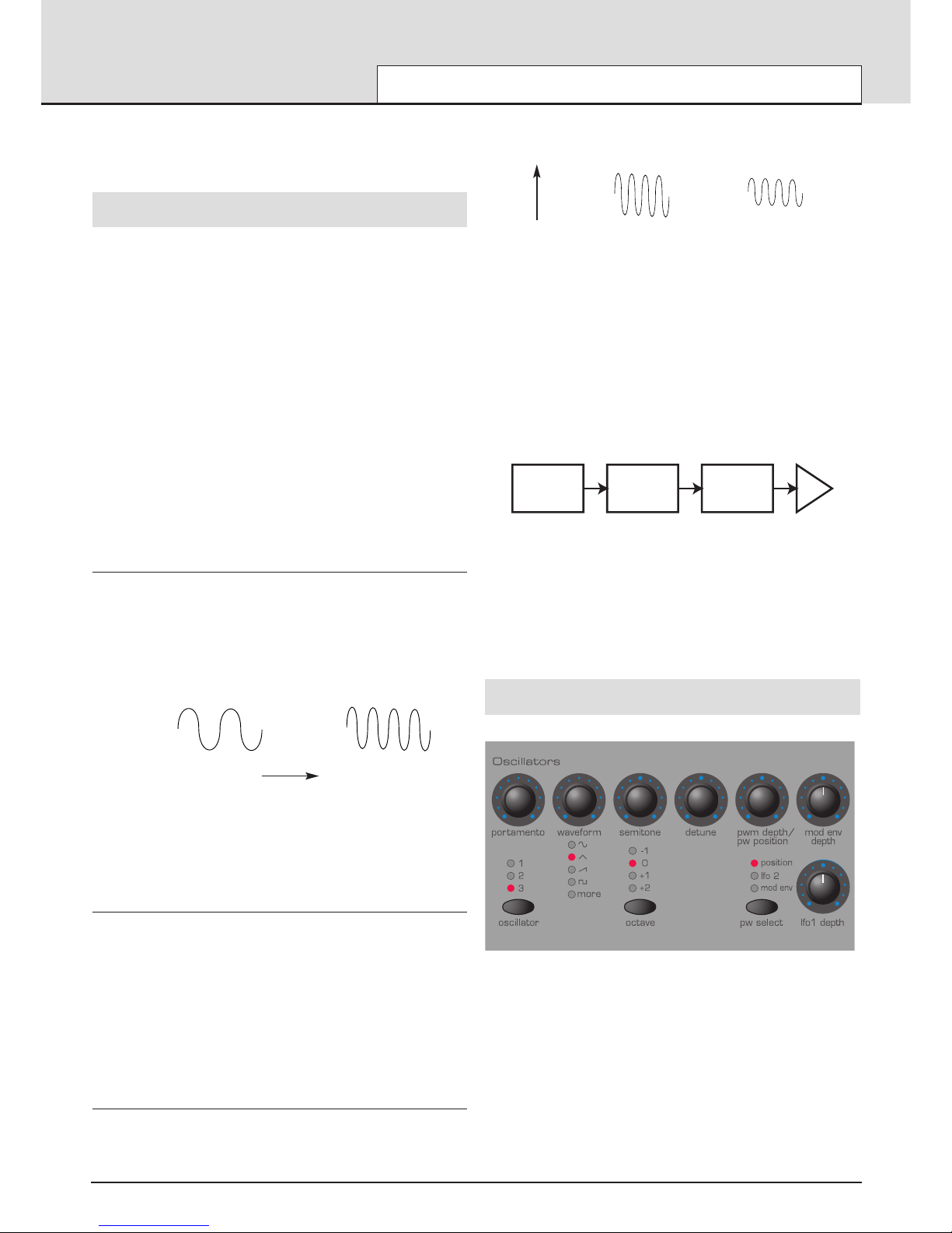
Oscillators and waveforms
The Oscillator is really the heartbeat of the Synthesizer. It generates an
electronic wave (which creates the vibrations). This Waveform is produced at a controllable musical pitch, initially determined by the note
played on the keyboard or contained in a received MIDI note message.
The initial distinctive tone or timbre of the waveform is actually determined
by the wave’s shape.
Many years ago, pioneers of musical synthesis discovered that just a few
distinctive waves contained many of the most useful harmonics for musical synthesis. The names of these waves reflect their actual shape when
viewed on an instrument known as an Oscilloscope, and are known as,
Sine waves, Square waves, Sawtooth waves, Triangle waves and Noise
Waves.
Each one has a specific fixed amount of musically related harmonics
(except noise waves) which can be manipulated by further sections of the
Synthesizer.
SYNTHESIS TUTORIAL
Elements of a sound - Oscillators and waveforms
• 9 •
Wave B
Wave A
Wave B is twice the pitch of Wave A
Time
Wave BWave A
Volume
Wave A is louder than Wave B but is the same pitch
Oscillators
Mixer Filter
Amplifier
Audio path of the main Synthesizer blocks
Page 10
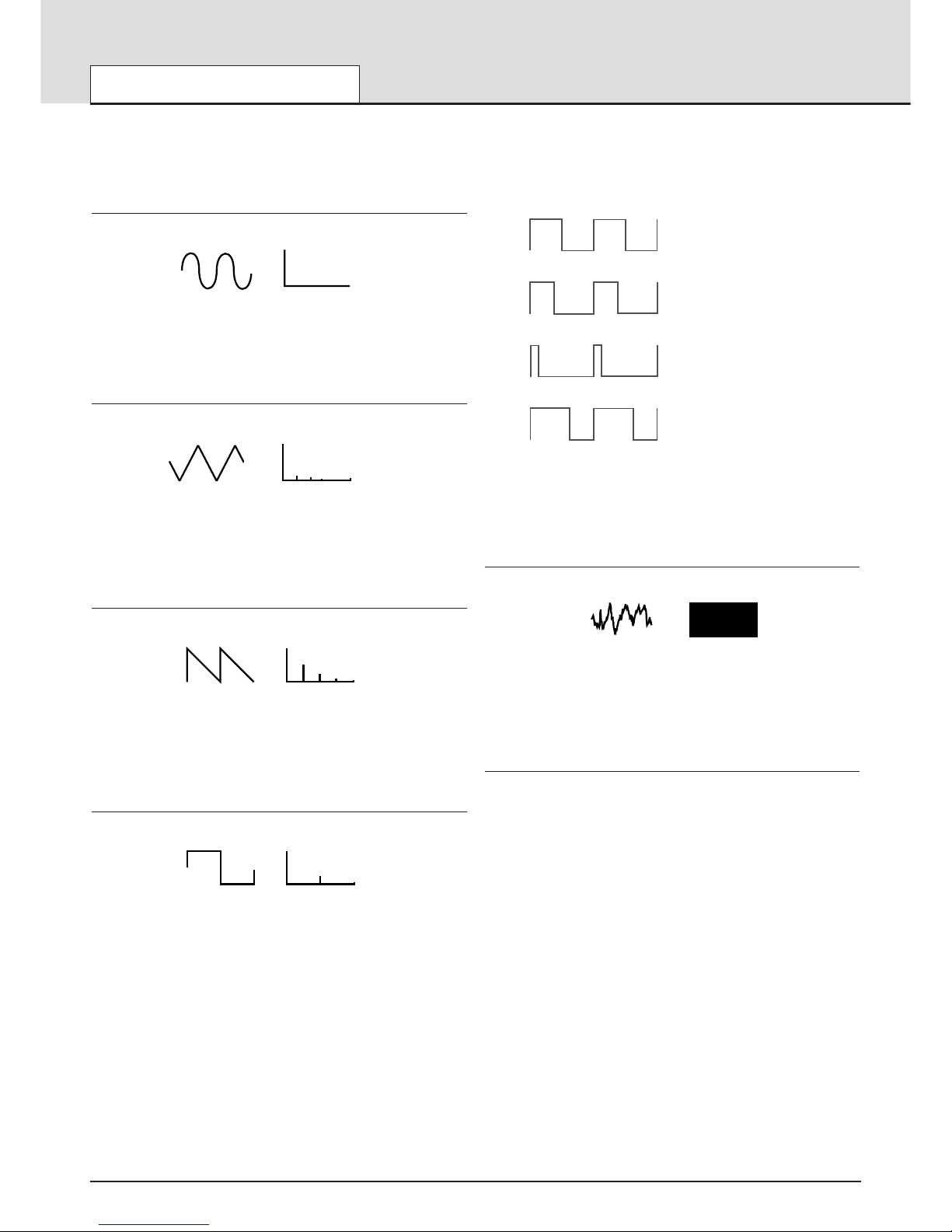
The diagrams below show how these waveforms look on an
Oscilloscope and illustrate the relative levels of their harmonics.
Remember, it is the relative levels of the various harmonics present in a
waveform which determine the tone of the final sound.
Sine waves
These have just a single frequency. This waveform produces the purest
sound because it only has this single pitch (frequency).
Triangle waves
These contain only odd harmonics. The volume of each is the square of
its position in the harmonic series. For example, the 5th harmonic has a
volume of 1/25th of the fundamental.
Sawtooth waves
These have a rich proportion of harmonics, containing all the harmonics of
the fundamental frequency. The volume of each harmonic is proportional
to its position in the harmonic series.
Square waves
These only have only the odd harmonics present. These are at the same
volume as the odd harmonics in a sawtooth wave.
It will be noticed that the square waveform spends an equal emount of
time in its ‘high’ state and its ‘low’ state. The way in which this defined is
known as the ‘duty cycle’. A square wave always has a duty cycle of 50%
which means it is ‘high’ for 50% of the waveform cycle and ‘low’ for the
remaining 50% of the waveform cycle.
On the KS 4 / KS 5 it is possible to adjust the duty cycle of the basic
square waveform to produce a waveform which is more ‘rectangular’ in
shape. These are often known as Pulse waveforms. As the waveform
becomes more and more rectangular, more even harmonics are introduced and the waveform changes its character, becoming more ‘nasal’
sounding.
The width of the pulse waveform (often known as ‘Pulse Width’) can be
altered dynamically by a modulator which results in the harmonic content
of the waveform constantly changing. This can result in the waveform
having a very ‘fat’ quality when the pulse width is altered at a moderate
speed.
When listening to a pulse wave, it does not make any difference to the
percieved sound whether the duty cycle is 40% or 60% since the waveform has just been inverted and the harmonic content between the two is
exactly the same.
Noise waves
These have no fundamental frequency (and therefore no pitched element).
All frequencies are at the same volume. Because they have no perceivable
pitch, noise waves are often useful for creating sound effects and percussion type sounds.
Digital waveforms
In addition to the traditional types of Oscillator waveforms detailed above,
the KS 4 / KS 5 also offers carefully selected digitally sampled preset
waveforms containing useful harmonic elements normally difficult to produce using traditional Oscillator waveforms.
SYNTHESIS TUTORIAL
Oscillators and waveforms
• 10 •
Volume
Harmonic
1
Sine Wave
Sine Wave
Harmonic
Volume
Volume
Harmonic
1357
Triaangle Wave
Triangle Wave
Harmonic
Volume
Sawtooth Wave
Volume
Harmonic
1234 5
Sawtooth Wave
Harmonic
Volume
Square Wave
Volume
Harmonic
1234 5
Square Wave
Harmonic
Volume
50%
40%
10%
60%
Various duty cycles of rectangular (pulse) waves
Noise
Volume
Harmonic
1234 5
Noise Harmonic
Volume
Page 11
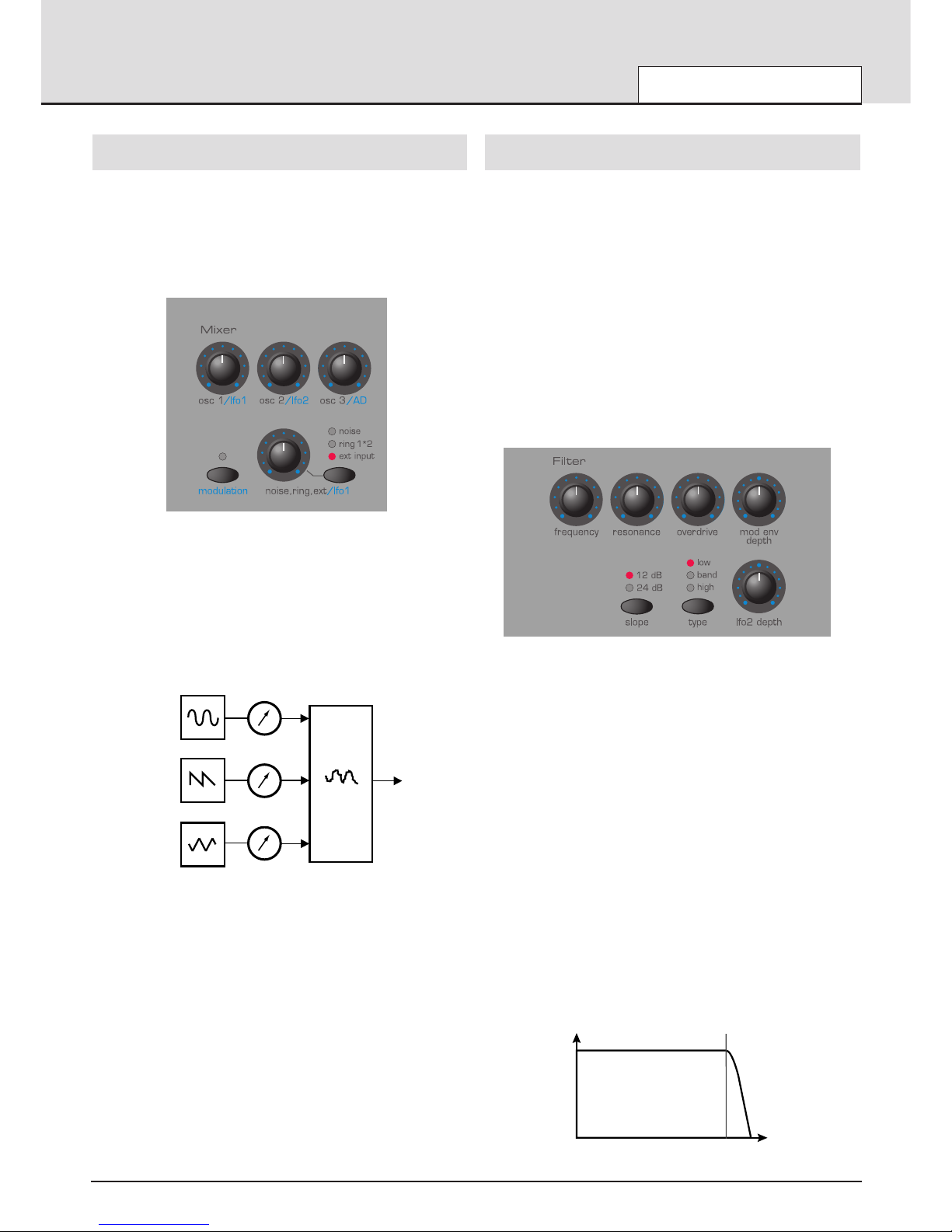
The Mixer
To extend the range of sounds that may be reproduced, a typical
Analogue synthesizer often has more than one Oscillator. By using more
than one Oscillator when creating a sound, it possible to achieve very
interesting harmonic mixes. It is also possible to slightly detune individual
Oscillators against each other which creates a very warm ‘fat’ sound.
There are has three independent Oscillators and a separate Noise
Oscillator.
The mixer section is included so that the amplitude (volume level) of each
of these Oscillators and Noise sources may be independently adjusted
and mixed together to form a new more harmonically complex waveform.
As well as mixing together the individual Oscillators as shown in the diagram above, the mixer section allows the relative volume levels of the
Noise Oscillator and any external sound source to be set.
The Filter
The KS 4 / KS 5 is an Analogue subtractive type of music synthesizer.
Subtractive implies that part of the sound is subtracted somewhere in the
synthesis process.
The Oscillators provide the raw waveforms with plenty of harmonic content and it is the Filter that subtracts unwanted harmonics in a controllable
manner.
Three types of Filter are available. The type of Filter most commonly
found on synthesizers is the Low Pass type. With a Low Pass Filter, a cutoff point is chosen and any frequencies below that point are passed. Any
frequencies above are filtered out. The setting of the FREQUENCY knob
on the front panel dictates the point below which frequencies are
removed. This process of removing harmonics from the waveforms has
the effect of changing the sound’s character or timbre. When the FREQUENCY knob is set fully clockwise, the filter is set completely open and
no frequencies are removed from the raw Oscillator waveforms.
In practice, there is a gradual reduction in the volume of the harmonics
above the cut-off point. How quickly these harmonics are reduced in vol-
ume above the cut-off frequency is determined by the Filter’s slope. This
slope is measured in ‘volume units per octave’. Since Volume is measured in decibels, this slope is quoted in number of decibels per octave
(dB). Typical values are 12dB or 24dB per Octave. The higher the number, the faster the harmonics are cut and the more pronounced the filtering effect.
The button on the sectionl marked SLOPE allows either the 12dB or 24dB
type filter slope to be selected.
A further important feature of the Filter is the RESONANCE control.
Frequencies at the cut-off point may be increased in volume by this control. This is useful for emphasizing certain harmonics of the sound.
As the RESONANCE is increased, a whistling like quality will be introduced to the sound passing through the filter. When set to very high levels, RESONANCE actually causes the filter to self - oscillate whenever a
signal is being passed through it. The resulting whistling tone being produced is actually a pure sine wave, the pitch of which depends on the setting of the FREQUENCY knob (the filter’s cut-off point). This resonanceproduced sine wave can actually be used for some sounds as an additional sound source if desired.
The diagram below shows the response of a typical low pass filter.
Frequencies above the cut off point are reduced in volume.
SYNTHESIS TUTORIAL
The Mixer - The Filter
• 11 •
OSC 1
OSC 1 VOLUME
OSC 2 VOLUME
OSC 3 VOLUME
COMPLEX
WAVEFORM
MIX OF
OSC1, 2 AND 3
MIXER
INPUT TO
FILTER
OSC 2
OSC 3
OSC 1
OSC 2
OSC 3
OSC 1 VOLUME
OSC 2 VOLUME
OSC 3 VOLUME
MIXER
INPUT TO
FILTER
COMPLEX
WAVEFORM
MIX OF
OSC1, 2 & 3
Frequency
Volume
Cutoff
Frequency
Volume
Frequency
Cut off
frequency
Page 12
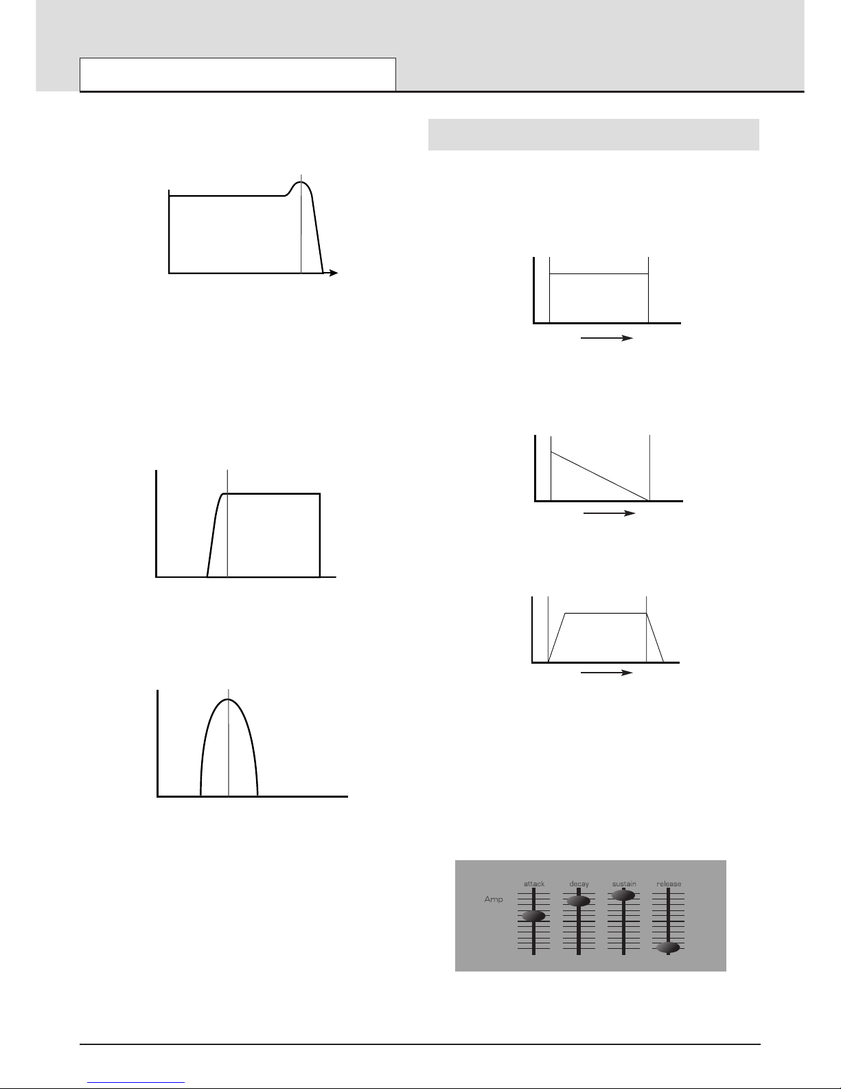
When resonance is added, frequencies at the cut off point are boosted in
volume.
In addition to the traditional Low Pass Filter type, there is also a High
Pass and Band Pass Filter. The type of Filter used is selected by using
the front panel Filter TYPE button.
The High Pass Filter is similar to the Low Pass Filter except that frequencies below the cutoff frequency point are removed. Frequencies above
that point are passed. When the FREQUENCY knob is set fully anti-clockwise, the filter is set completely open and no frequencies are removed
from the raw Oscillator waveforms.
When the Band Pass Filter is used, only a narrow band of frequencies
centered on the cutoff frequency point are removed. It is not possible to
fully open this type of Filter, allowing all frequencies to pass through.
Envelopes and Amplifier
In earlier paragraphs, it was determined how the pitch and timbre of a
sound are synthesized. This final part of the Synthesis Tutorial describes
how the volume of sound is controlled. The volume throughout the duration of a sound created by a musical instrument often varies greatly
according to the type of instrument.
An Organ sound quickly attains full volume when a key on the keyboard is
pressed. It stays at full volume until the key is released, at which point the
volume level falls instantly to zero.
A Piano
quickly attains
full volume when a key is pressed and gradually
falls back down to zero after several seconds, even if a key is held.
A String Section emulation
attains
full volume gradually when a key is
pressed. It remains at full volume while the key is held down, but once the
key is released, the volume level gradually falls to zero.
On an Analogue synthesizer, changes which occur throughout the duration of a note are controlled by a section known as an Envelope
Generator. The KS 4 / KS 5 has two Envelope Generators. The circuit of
one of these is always connected to an Amplifier, which controls the
Volume of the sound when a note is played.
Note that there are no controls in a section on the front panel which deal
with the Amplifier directly. The only way to hear and control an audio signal passing through the Amplifier is to modulate it by using Amp Envelope
controls.
Each envelope generator has four controls which are used to adjust the
shape of the envelope. The Envelope controlling the Amplifier uses sliders.
Volume
Frequency
Cutoff
Frequency
SYNTHESIS TUTORIAL
The Filter - Envelopes and Amplifier
• 12 •
Volume
Frequency
Frequency
Volume
Cutoff
Frequency
Cut off
frequency
Frequency
Volume
Cutoff
Frequency
Key "On" Key "Off"
Volume
Key “On”
Key “Off”
Volume
Time
Key "On" Key "Off"
Volume
Key “On”
Key “Off”
Volume
Time
Key "On" Key "Off"
Volume
Key “On”
Key “Off”
Volume
Time
Page 13
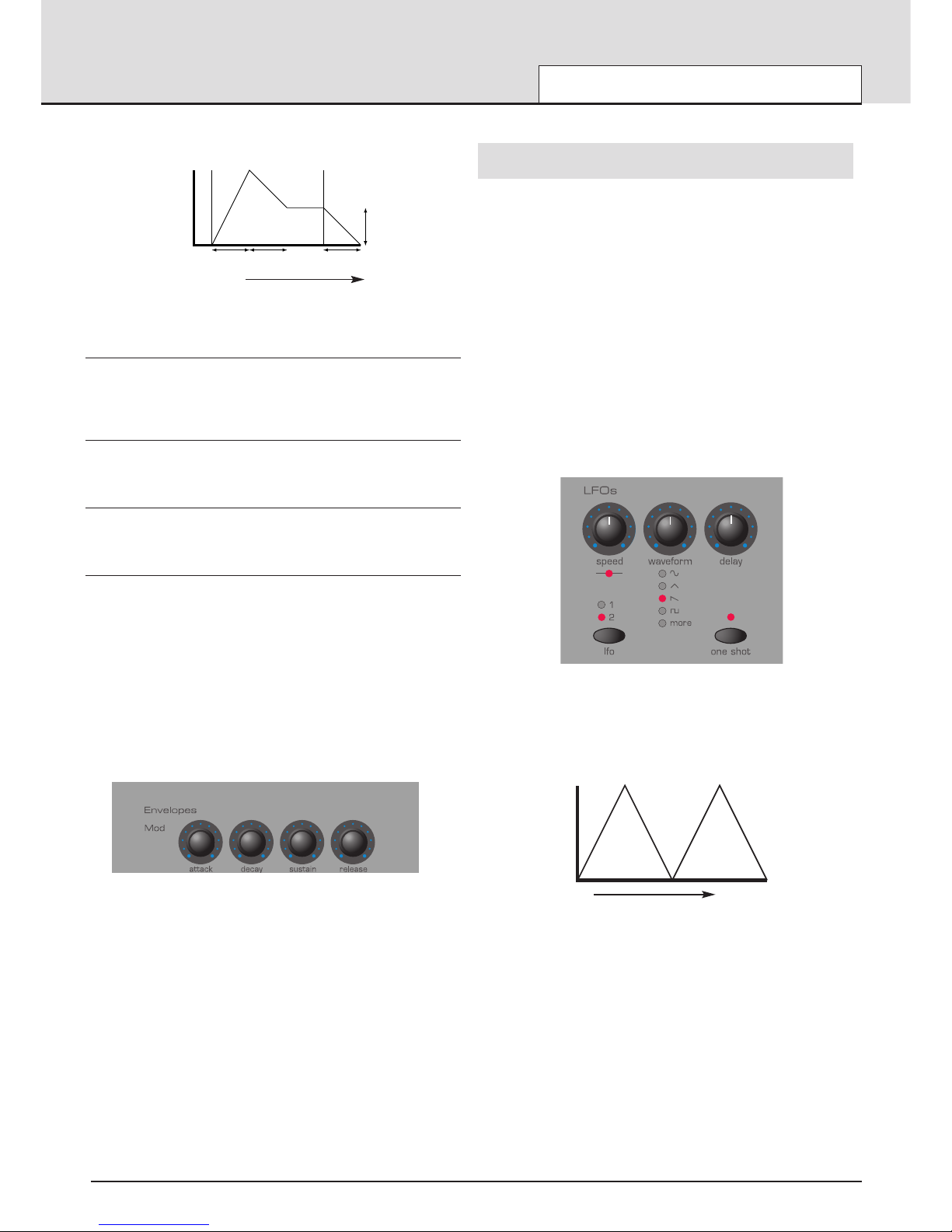
When controlling Volume, these controls adjust the following phases of
the Envelope as shown in the illustration.
A = Attack Time
Adjusts the time it takes when a key is pressed for the envelope to climb
from zero to full volume. It can be used to create a sound with a slow fade
in.
D = Decay Time
Adjusts the time it takes for the envelope to decay from full volume to the
level set by the Sustain control while a key is held down.
S = Sustain Level
Sets the volume level that the envelope remains at while the key is held
down, after the Decay time has expired.
R = Release Time
Adjusts the time it takes when key is released from the Sustain level to
zero. It can be used to create sounds that slowly fade away in volume.
A typical synthesizer will have one or more envelopes. One envelope is
always applied to the amplifier to shape the volume of each note played.
Additional envelopes can be used to dynamically alter other sections of
the synthesizer during the lifetime of each note.
The KS 4 / KS 5 has a second Envelope Generator which may be applied
in various interesting ways. For example, it may typically be used to modify the filter cut off frequency or change an oscillators pitch during the lifetime of a note.
LFOs
Like the Envelope Generators, the LFO section on a synthesizer is a
Modulator. That is to say, instead of forming a part of the sound synthesis
process, it is used instead to change (modulate) other synthesizer sections. For example, altering the Oscillator pitch or Filter cutoff frequency.
Most musical instruments produce sounds that vary not just in volume but
also in pitch and timbre. Sometimes this variation can be quite subtle, but
still contribute greatly towards shaping the final sound.
Where an Envelope is used to control a one-off modulation which occurs
during the lifetime of a single note, LFOs modulate by using a cyclic
repeating wave pattern. As discussed earlier, Oscillators produce a constant waveform which can take the shape of a repeating sine wave, triangle wave etc. LFOs produce waveforms in a similar way, but at a frequency normally too low to produce an audible pitched vibration that the
human ear can perceive. In fact, LFO actually stands for Low Frequency
Oscillator.
As with an Envelope, the waveforms generated by the LFOs may be fed
to other parts of the synthesizer to create the desired movements in the
sound.
There are two independent LFOs available which may be used to modulate different synthesizer sections and run at different speeds.
A typical waveshape for an LFO would be a Triangle wave.
Imagine this slow moving wave being applied to an Oscillator’s pitch. The
result would be that the pitch of the Oscillator slowly rises and falls above
and below its original pitch.
This would simulate, for example, a violinist moving a finger up and down
the string of the instrument whilst it is being bowed. This subtle up and
down movement of pitch is referred to as the ‘Vibrato’ effect.
Similarly, if the same LFO were applied to the Filter Cutoff frequency
instead of the Oscillator pitch, a similar wobbling effect known as ‘wowwow’ would be heard.
As well as LFOs being available to modify (or more commonly known as
Modulate) different sections of the synthesizer, additional Envelopes may
also be used simultaneously.
Clearly, the more Oscillators, Filters, Envelopes and LFOs there are in a
Synthesizer, the more powerful it becomes.
SYNTHESIS TUTORIAL
Envelopes and Amplifier - LFOs
• 13 •
Attack
Decay Release
Sustain
Key "On" Key "Off"
Time
Volume
Key “On”
Key “Off”
Volume
Attack Decay
Release
Sustain
Level
Time
Time
Pitch
Page 14

Memories
The first generation of synthesizers, produced many years ago were large
modular machines where each part of the synthesizer was housed in a
separate unit (block). These blocks could only be physically connected
together by combinations of cables known as patch leads. A typical sound
produced by this method would often involve connecting dozens of patch
leads.
Every time a new sound was required, the leads would have to be physically disconnected and reconnected. The positions and connections of the
leads would have to be noted down on paper if there was to be any hope
of creating that particular sound ever again ! If not reconnected in exactly
the same way, the sound would be lost forever.
Modern machines such as the KS 4 / KS 5 have all the blocks in one
compact unit and the sound generating or modifying blocks are arranged
in a sensible fashion. Front panel switches and knobs determine how
each block functions and where the sound modifying blocks such as the
LFOs and Envelopes are routed, instead of having to physically connect
them externally with cables.
Additionally, The settings of these front panel controls (which of course
determine the current sound or ‘patch’) may then be stored in memory
locations in the machine which can be recalled at any time.
Summary
An Analogue synthesizer can be broken down into five main sound generating or sound modifying (modulating) blocks.
1 Oscillators that generate Waveforms at a certain
pitches.
2 A Mixer that mixes the outputs from the Oscillators
together.
3 A Filter that removes certain harmonics, which changes
the characteristic or timbre of the sound.
4 An Amplifier that is controlled by an Envelope
generator. This alters the volume of a sound over
time when a note is played.
5 LFOs and Envelopes that can be used to modulate
any of the above.
Much of the enjoyment to be had with a Synthesizer is with experimenting
with the factory preset sounds and creating new ones. There is no substitute for ‘hands on‘ experience. Experiments with altering knobs and
switches will eventually lead to a fuller understanding of how the various
controls alter and help shape new sounds.
Armed with the knowledge in this chapter, and an understanding of what
is actually happening in the machine when tweaks to the knobs and
switches are made, the process of creating new and exciting sounds will
become easy - Have fun.
SYNTHESIS TUTORIAL
Memories - Summary
• 14 •
Page 15
It is recommended that this chapter is read carefully if you are unfamiliar
with how MIDI works. Experienced users can skip this chapter and move
on to the next chapter Main Features and Operation on page 18.
About MIDI
MIDI is an acronym for Musical Instrument Digital Interface. The MIDI
standard was devised in the early 80’s as a means for allowing musical
instruments to communicate with each other as well as with other devices
such as sequencers and computers. Before the advent of MIDI, it was
often very difficult (if not impossible) for instruments to effectively communicate with each other, especially if they had been made by different manufacturers. Nowadays, most types of electronic musical equipment are
equipped with a MIDI interface fitted as standard, including synthesizers,
drum machines, samplers, sequencers, computers and even some effects
units.
The MIDI standard allows many different instruments to be controlled at
once (say from a sequencer) using the same network of MIDI cables.
Each instrument in the MIDI chain is usually assigned its own unique MIDI
channel and will only respond to information that it may receive on that
particular channel. The MIDI standard allows for sixteen different channels
to be assigned to the various instruments in a MIDI network, which of
course means that it is possible to have up to sixteen instruments playing
simultaneously within a MIDI system.
Some people may feel that being restricted to just sixteen MIDI channels
might be a little limiting, especially if they are composing very complex
pieces of music. However, some sequencers and MIDI ports for computers offer a neat way around this problem. They can offer several different
MIDI outputs, each of which is treated as a separate MIDI system in its
own right with its own set of sixteen MIDI channels.
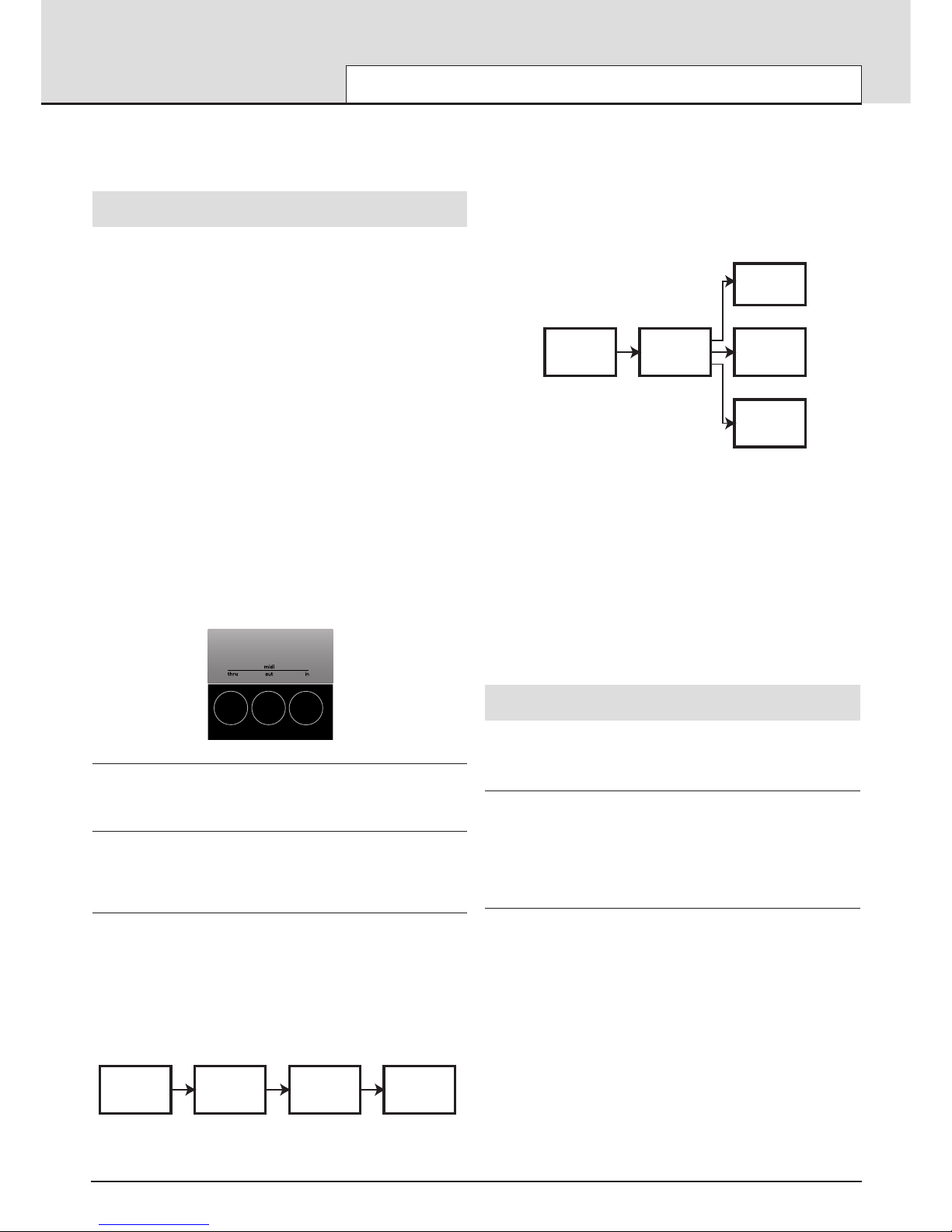
There are three MIDI sockets fitted at the rear, labeled ‘In’, ‘Out’ and
‘Thru’. Each one of these sockets has a specific purpose :
The MIDI IN Port
This is used to receive MIDI information to the KS 4 / KS 5, such as
telling it which notes to play from a sequencer for example.
The MIDI OUT Port
This transmits any MIDI information which might be generated by the KS
4 / KS 5. For example, if a note was played on the keyboard or one of the
knobs were moved on the front panel.
The MIDI THRU Port
This simply re-transmits any MIDI information that has been received at
the MIDI In socket. This socket is useful for connecting other instruments
into the same MIDI network. By connecting a cable from the MIDI Thru to
another instrument’s MIDI In socket, both the KS 4 / KS 5 and the second
instrument could be controlled simultaneously from a sequencer.
As seen in the diagram, if desired, the process can be repeated; a third
instrument could be added to the same MIDI network, simply by connecting a cable from the second instrument’s MIDI Thru to the third instrument’s MIDI In, and so on.
Some non-Novation instruments may not have a MIDI Thru socket fitted.
In these cases, the instrument should be placed at the end of the MIDI
chain or a Thru box should be incorporated into the MIDI system.
A Thru Box simply provides a number of identical MIDI Thru sockets from
a single MIDI In.
It is important to realise that MIDI information flows in one direction only
along the cable. It is not possible to have a MIDI In socket connected to
another MIDI In socket for example. If this were done, the MIDI network
would simply not work ! In fact, the only routings allowed are MIDI Out to
MIDI In or MIDI Thru to MIDI In.
Some devices known as controllers are equipped with only a single MIDI
Out socket and are used exclusively to generate MIDI data for controlling
other instruments. Examples of common MIDI controllers are controller
keyboards (these are simply keyboards with no synthesizer attached),
drum percussion pads or footswitch controllers.
MIDI messages
The KS 4 / KS 5 is capable of transmitting and responding to various
types of MIDI events. These are as follows :
NOTE MESSAGES
A note message is transmitted every time a key on the keyboard is
pressed down or released. When a keyboard note is pressed down, the
MIDI message also includes velocity information. The velocity value in the
MIDI message represents how hard the key was pressed down. This
velocity value can be used to add dynamics to the sound, depending on
how hard the note was played.
CONTROL CHANGE MESSAGES
These messages are transmitted whenever one of the knobs or sliders
are moved on the front panel. Most parameters within a menu will also
transmit MIDI control change messages when the parameter is altered
with the DATA knob. The MIDI specification allows for 128 different types
of controller message. These are often referred to as Continuous
Controllers (CC0 to CC127).
Some controllers are rigidly defined by the MIDI standard for specific purposes. For example, CC1 is always used for the modulation wheel.
Whenever the modulation wheel is moved, it will transmit MIDI control
change information using CC1. All other makes of synthesizers will also
use CC1 for modulation wheel data.
Certain other control change numbers have no set purpose within the
MIDI specification. For example, whenever the Filter FREQUENCY knob
is moved, it will transmit using CC105. There is no guarantee however
that other makes of synthesizer will use this control change number for
the same purpose.
MIDI TUTORIAL
About MIDI - MIDI messages used by the KS 4 / KS 5
• 15 •
Out
In
Thru
In
InThru
Sequencer
Synth [1] Synth [2]
Synth [3]
‘Chain’ method of connecting three MIDI
devices to a sequencer
Out
In
In
In
In
Thru
Thru
Thru
Sequencer
Synth [1]
Synth [2]
Synth [3]
‘Star’ method of connecting three MIDI
devices to a sequencer
MIDI Thru Box
Page 16

There are more than 128 different parameters that can be transmitted by
MIDI, but because the number of different types of control change message is limited to just 128, a a more complicated arrangement had to be
employed for additional parameters.
This method uses what is known as NRPNs. (NRPN stands for Non
Registered Parameter Number). NRPNs consist of three MIDI control
change messages grouped together, rather than a single MIDI control
change message which is used normally.
PITCH BEND MESSAGES
These messages are transmitted whenever the pitch bend wheel is
moved.
AFTERTOUCH MESSAGES
These messages are transmitted by some keyboards whenever alreadyheld down keyboard notes are pressed further. Aftertouch messages can
be used to add extra expressiveness to a sound, for example introducing
an extra vibrato effect.
The MIDI specification defines two different types of aftertouch message;
mono and poly. The type used by the KS 4 / KS 5 is mono. Poly aftertouch includes information in the MIDI message about which keyboard
note was used to trigger the aftertouch effect. Poly aftertouch is very
rarely used and only a very few synthesizers ever implemented the system.
PROGRAM CHANGE MESSAGES
These messages are transmitted whenever a new sound is selected from
the front panel. The MIDI Specification allows a MIDI program change
message to select one of 128 different sounds. When the MIDI specification was originally designed, this was not a problem since synthesizers in
rarely had more than 128 memories.
Modern synthesizers such as the KS 4 / KS 5 offer many more memories,
so it is necessary to send a MIDI program change preceded by an additional MIDI message which specifies which ‘bank’ of sounds the program
change message will select from.
The bank select MIDI message used for this purpose is a MIDI control
change message (CC32 is the control change number used). Whenever a
new sound is selected, the bank select MIDI message is transmitted, followed closely by the appropriate MIDI program change message.
If these messages are then layed back to the KS 4 / KS 5 from a
sequencer, the appropriate sound will be selected.
It is not necessary to send a bank select message before the program
change message (though recommended). It is permitted to omit the bank
select, but if so, the program change message will select the sound from
whatever bank of sounds is currently selected.
Channel Messages
All of these different types of MIDI message detailed above include information detailing which MIDI channel was used when the message was
transmitted. MIDI channel messages only affect receiving devices using
the same MIDI channel. For example, a pitch bend message sent using
MIDI channel 1 would have no effect if it were received on a synthesizer
set to respond on MIDI channel 2.
Some MIDI messages do not include any MIDI channel information
defined in them. Some examples of these are :
MIDI CLOCK MESSAGES
These are synchronization messages sent from a sequencer. When
received, they enable tempo-locked features such as the arpeggiator and
various effects parameters (such as Panning and Delay sync) to follow
the current tempo of the sequencer.
The KS 4 / KS 5 itself does not transmit MIDI clock messages, so it can
only be synchronized to follow the tempo of other devices and not vice
versa.
Whenever an external sequencer is started, a Start Song MIDI message
is usually transmitted. Certain features can be set to reset their synchronisation when a Start Song message is received.
SYSTEM EXCLUSIVE MESSAGES
This is special type of MIDI message which can contain any type of data,
depending what the synthesizer manufacturer decides to put in it! The
only constraint with system exclusive messages is that they always contain certain header information which is exclusively used by the manufacturer (and usually the relevant synth model as well).
This means that a KS 4 / KS 5 will only accept a system exclusive message designed especially for it. If it receives a system exclusive message
transmitted by a different make of synthesizer, the message would simply
be ignored. Similarly, other makes of synthesizer will ignore any system
exclusive messages originally sent by a KS 4 / KS 5.
System exclusive messages have employed for two distinct purposes.
They can be used to back up all of the Program, Drum Map and
Performance memories and global data. This feature is extremely useful
in building up a sound library on a computer or for making a safety copy
of data in case the worst should happen.
Data backup is discussed in detail on Page 49 in the Advanced Features
chapter.
System exclusive messages also enable an entire new operating system
to be received via MIDI. The latest operating system is always available
free of charge at the Novation web site. From there, it can be downloaded
as an SMF (Standard MIDI File).
Because the operating system update consists purely of MIDI system
exclusive messages, it can then be transferred by playing the file on a
sequencer directly into the machine. However, as a safety feature, the KS
4 / 5 must be set to a special mode where it is able to accept an operating
system update. Full details on how to do this are supplied along with the
downloaded OS update.
For a list of the latest operating system updates, please visit the Novation
website :
http://www.novationmusic.com
A MIDI Implementation Chart provides a concise way of telling at a glance
which MIDI messages an instrument will transmit and respond to. A MIDI
Implementation Chart for the KS 4 / KS 5 can be found on page 57. How
it transmits and responds to MIDI in the different playing modes is also
described in detail on page 56.
MIDI TUTORIAL
MIDI messages
• 16 •
Page 17
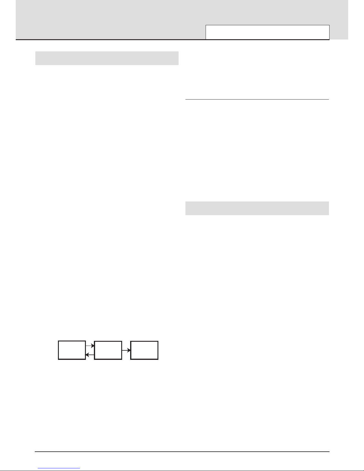
MIDI and Sequencers
A sequencer is simply a device which is capable of recording, storing and
playing back MIDI information. Using a sequencer, it is possible to construct very complex musical arrangements which would normally be
impossible to play ‘live’. It is also very easy to edit the MIDI data and
remove any unintended mistakes or make changes in the playing style.
Many people nowadays use software sequencing packages on computers, but there are also dedicated hardware sequencers available which
perform in a similar way.
All sequencers can record MIDI information exactly as played on the synthesizer’s keyboard. To do this, simply make sure the MIDI Out is connected to the sequencer’s MIDI In and start the sequencer recording. Any
keys played on the keyboard or knob / wheel movements made will be
faithfully recorded. This is known as ‘real time’ recording. As long as the
sequencer’s MIDI Out is connected to the KS4 / KS5’s MIDI In, this MIDI
information can then be played back into the KS4 / KS5, exactly reproducing all the actions made and notes played while recording the sequence.
On most sequencers, it is also possible to enter new MIDI events in ‘step
time’ by explicitly defining each MIDI event without having to supply the
relevant MIDI data to the sequencer’s MIDI In socket. Obviously, some
knowledge of MIDI is needed in order to do this.
Nearly all sequencers offer multiple recording tracks. These tracks behave
in a similar fashion to multi-track tape recorders, except that instead of
holding audio recordings, they hold their own record of MIDI data. Usually,
each sequencer track will contain MIDI data associated with a distinct
MIDI channel. By using sequencer tracks in this way, it would typically be
possible to build up a complex song arrangement with one track being
used to control the drums, another the bass line, another the lead sound
and so on.
When using a sequencer, some careful thought should be given as to the
way the MIDI information is routed through the sequencer. With most
sequencers, any MIDI information that appears at the sequencer’s MIDI In
socket is immediately re-transmitted again from the sequencer’s MIDI Out
socket. If desired, it is sometimes possible to turn this feature off. It usually called ‘echo back’ or ‘soft thru’. Consult your sequencer manual for
details.
It is very important to realise that if ‘soft thru’ is enabled on a sequencer,
the MIDI information re-transmitted by the MIDI Out socket is always converted to the MIDI channel used by the currently selected sequencer
track. This means that if a track is selected on a sequencer which uses
MIDI channel 2, and the sequencer then receives some MIDI information
from a KS 4 / KS 5 sent on MIDI channel 1, it will be re-transmitted by the
sequencer not on MIDI channel 1, but MIDI channel 2. This would be
quite useful for programming parts into the sequencer for other MIDI
devices or Parts, but can lead to some quite unexpected results if careful
note is not kept of exactly what is happening !
Because many sequencers re-channelise MIDI information in this way, it
is quite possible to use the KS4 / KS5 as a master keyboard to supply
MIDI information and notes that the sequencer will use to control other
Parts in a Performance or other external MIDI equipment such as a sampler.
In Performance Mode, each of the four Parts can be played simultane-
ously with each Part responding on its own unique MIDI channel. To
reflect this, four tracks should be configured on the sequencer with each
track’s MIDI channel setting reflecting the channel used on each of the
four KS4 / KS5 Parts. When the KS4 / KS5 is being used multi-timbrally in
this manner, when recording MIDI data from the KS4 / KS5, make it a
rule-of-thumb to always select the appropriate sequencer track before
selecting the Part on the KS4 / KS5’s front panel.
When controlling external MIDI equipment (in this example a sampler), the
sequencer track must be selected which corresponds to the same MIDI
channel that the sampler is using. However, it would be noticed that as
soon as notes are played into the sequencer from the KS 4 / KS 5 keyboard, the KS 4 / KS 5 would play as well as the sampler. To overcome
this problem, there is a feature available called Local Control.
Local Control
Local Control is a parameter found in the Global Menu (see page 50 for
details) which in effect, disconnects the keyboard and panel controls from
the synthesis engine.
When the keyboard is played or the front panel controls are moved, they
still transmit the usual MIDI information but they have no direct control of
the internal sound engine. When Local Control is set to OFF, the only
way that the keyboard or controls can be used to play the sound engine is
when the MIDI information sent from the keyboard is routed through the
sequencer (with the correct sequencer track selected), back to the MIDI In
socket.
When not connected correctly to a sequencer, having Local Control set
to OFF is a common cause of mistakenly assuming that the machine is
faulty. When the KS 4 / KS 5 appears to ignore its keyboard and front
panel controls, setting Local Control to ON or selecting the correct
sequencer track will usually rectify the ‘problem’.
See page 50 for altering the Local Control setting.
Summary
MIDI information is transmitted whenever the keyboard is played, front
panel controls are moved or when a new Program is selected.
MIDI information is split into 16 channels. The KS 4 / KS 5 can be set to
receive / transmit on any one of these channels at any one time in
Program Mode. When used in Performance Mode, up to four Parts can be
individually set to receive on different MIDI channels.
MIDI information travels in one direction along a MIDI cable. The only permitted connections are MIDI Out to MIDI In, or MIDI Thru to MIDI In.
MIDI messages can be recorded into a sequencer and later replayed back
into the KS 4 / KS 5, replicating whatever actions occurred when the MIDI
messages were originally transmitted.
Sequencers usually re-transmit any MIDI information they receive immediately, converting the message’s channel information into whatever MIDI
channel the currently selected sequencer track is using.
Because of this, the KS 4 / KS 5 may be used as a ‘Master Keyboard’ to
control all MIDI devices in a MIDI network.
An option called Local Control disables the keyboard and controls from
the synthesizer engine. When set to OFF, playing the keyboard or moving
the front panel controls only results in MIDI information being transmitted.
Setting Local Control to OFF allows the KS 4 / KS 5 to control other
MIDI instruments without triggering notes or altering settings on the KS 4 /
KS 5 directly.
MIDI TUTORIAL
MIDI and Sequencers - Summary
• 17 •
Sequencer KS 4 / KS 5
Synth [2]... etc
Out
Out
In
In
In
Thru
Typical example of using the KS 4 / KS 5
as a Master Keyboard in a MIDI system
‘Soft Thru’
set to On
Page 18
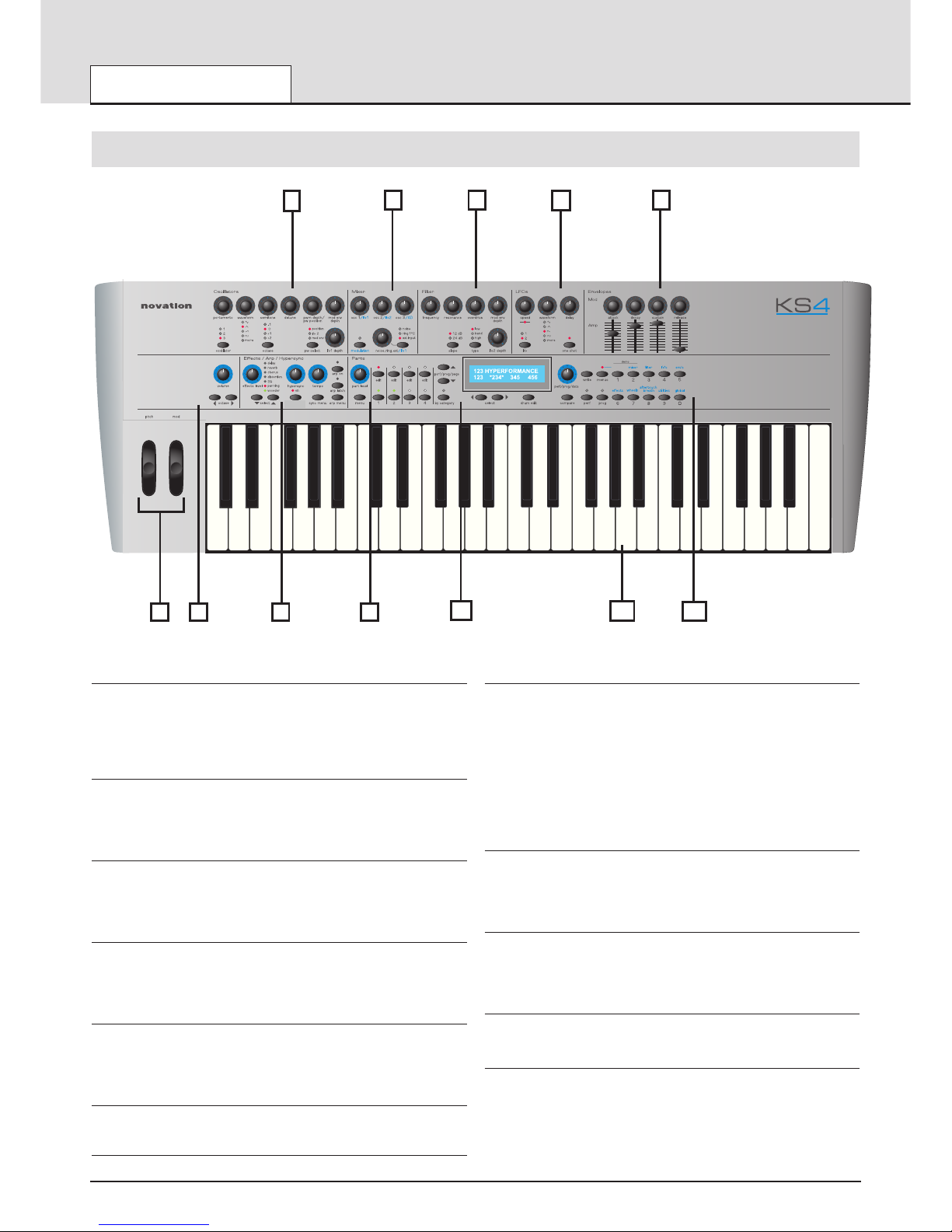
1 - Oscillator Section
Contains the controls associated with the Oscillators. These include the
PORTAMENTO, WAVEFORM, SEMITONE tune, DETUNE, PWM DEPTH
/ PW POSITION, MOD ENV DEPTH and LFO 1 DEPTH knobs and the
OSCILLATOR select, OCTAVE and PW SELECT buttons.
2 - Mixer Section
Contains the controls associated with the Mixer. These include the OSC 1
/ LFO 1, OSC 2 / LFO2, OSC 3 / AD and NOISE / RING / EXT / LFO 1
knobs and the MODULATION and NOISE / RING / EXT buttons.
3 - Filter Section
Contains the controls associated with the Filter. These include the FREQUENCY, RESONANCE, OVERDRIVE, MOD ENV DEPTH and LFO 2
DEPTH knobs and the SLOPE and TYPE buttons.
4 - LFO Section
Contains the controls associated with the two LFOs. These include the
SPEED, WAVEFORM and DELAY knobs and the LFO and ONE SHOT
buttons.
5 - Envelopes Section
Contains controls associated with the two Envelopes. These are two sets
of ATTACK, DECAY, SUSTAIN and RELEASE controls. Knobs are used
for the MOD Envelope and Sliders are used for the AMP Envelope.
6 - Performance Controls Section
Pitch and Modulation wheels
7 - Master Volume and Keyboard Octave buttons
Contains the PITCH bend and MODulation wheels.
8 - Effects / Arpeggiator / Hypersync Section
Contains controls associated with the Effects, Arpeggiator and Hypersync
feature.
For the Effects, these include the EFFECTS LEVEL knob and SELECT
buttons.
For the Arpeggiator, these include the TEMPO knob and the ARP ON,
ARP LATCH and ARP MENU buttons.
For the Hypersync feature, these include the HYPERSYNC knob and the
SAVE HYPER and SYNC MENU buttons.
9 - Part Section
Contains controls associated with editing and selecting Parts. These
include the PART LEVEL knob, the four Part EDIT buttons, the four Part
Activate buttons and the Part MENU button.
10 - Display and Data Entry Section
Contains the display, the PERF / PROG / DATA knob and the PERF /
PROG / PAGE, BY CATEGORY, SELECT, DRUM EDIT and COMPARE
buttons.
11 - Keyboard
Four octaves are available on the KS 4, five octaves on the KS 5.
12 - Mode and Keypad Section
Contains the WRITE, MENUS, PERF, PROG buttons and the numeric
keypad / Menu select buttons.
MAIN FEATURES AND OPERATION
Front Panel Layout
• 18 •
osc's
save hyper
Front Panel Layout
1
2 3 4 5
6 7 8 9
10 11
12
Page 19
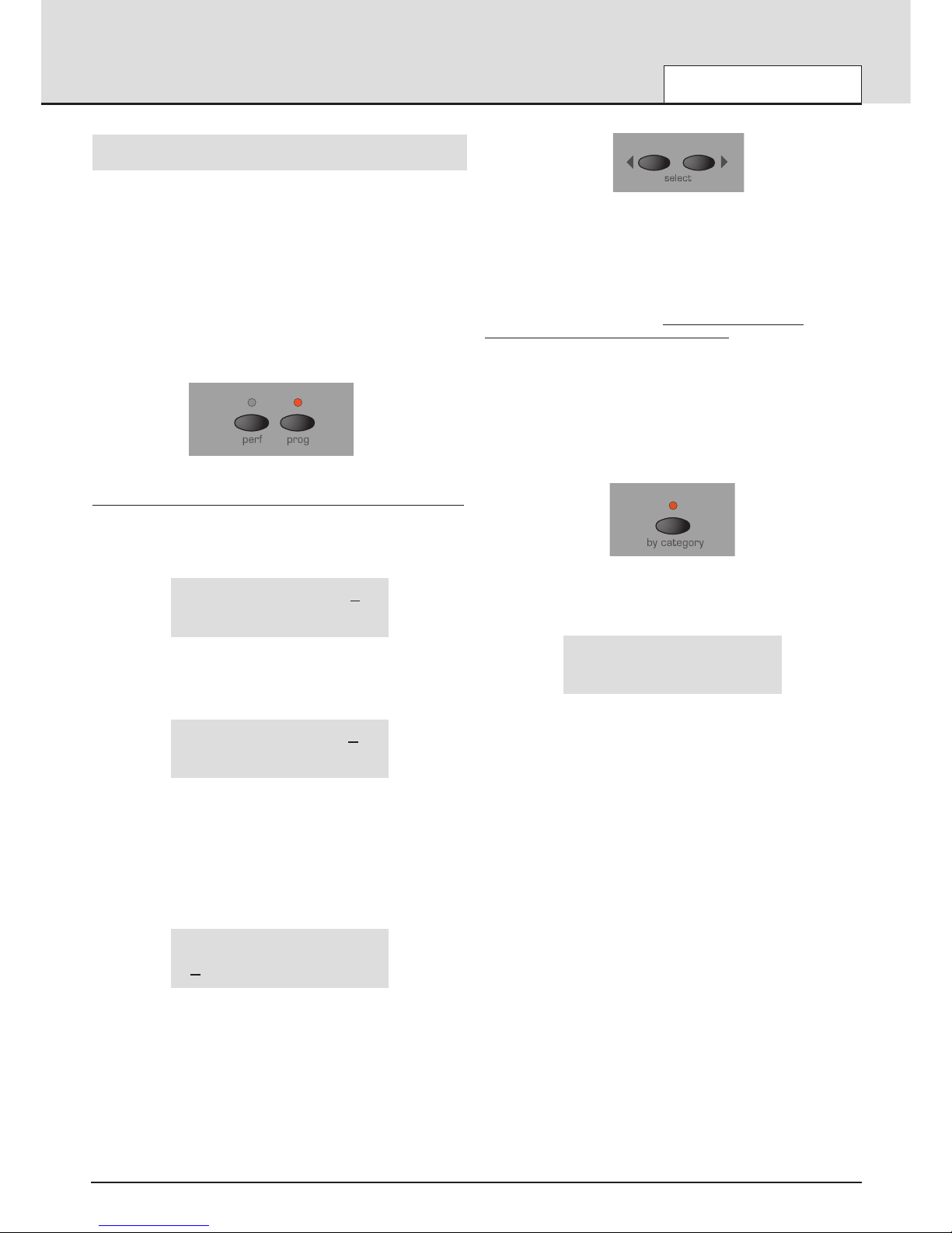
Modes and Menus
As described in the Quick Start Guide, in Program Mode, the machine
operates in a mono-timbral (just one sound available) mode and responds
to, and sends information on just one MIDI channel. This mode should be
used when only one sound is required for playing, or when individual
sounds are to be auditioned.
In Performance Mode, additional information is added to each sound
(Program) such as MIDI channel and note range and this complete set of
information is stored in what is known as a Part. Up to four of these Parts
can then be used simultaneously in a Performance.
The LEDs located above the PROG and PERF buttons indicate which
playing mode is selected.
Program and Peformance Modes
This mode enables a new single Program (sound) to be selected from
the front panel controls. Program Mode is selected by pressing the
PROG button. Selecting Program Mode cancels Performance mode.
Program’s name 101
In Program Mode, the display will show the currently selected Program’s
name and number. Performance Mode is selected by pressing the PERF
button. Performance Mode is cancelled when Program mode is selected.
Performance name 101
123 234 345 456
In Performance Mode, the display shows the selected Performance’s
name and number on the top line of the display. The four sets of numbers on the bottom line are the Program number references that are
asigned to each of the four Parts.
If the cursor is located at the Performance number, a new Performance
can be selected by using either the data knob, up/down buttons or the
keypad.
Performance name 101
123 234 345 456
Moving the cursor to any of the Part numbers allows a new Program or
Drum Map to be selected for a Part.
The cursor is moved using the SELECT left and right buttons.
Pressing the SELECT LEFT button will position the cursor at the first program at the bottom left of the display. Pressing the SELECT RIGHT button will position the cursor at the fourth program at the bottom right of the
display. Subsequenct presses of either button will move the cursor one
step left or right to select the next Program.
Once the cursor is positioned over a Program number it is possible to
select a new Program to be used in the Performance by any of the methods described in the following text. T
o return to selecting a new
Performance the PERF button must be pressed.
A new Program or Performance may be selected by one of three methods.
i) The PERF / PROG / DATA knob may be used. Turning the knob quickly
increases the intervals jumped between Programs / Performances.
When selecting Programs, the BY CATEGORY button may be used to
search only for Programs within a specific category.
When pressed, the LED above the BY CATEGORY button lights to indicate that category searching is active. The display shows the category
assigned to the currently selected Program.
Program’s name 101
Bass
It is possible to select a different category for searching by using the
SELECT left and right buttons.
While category searching is active, the PERF / PROG / DATA knob will
only select Programs saved with the currently selected category.
To cancel category searching, press the BY CATEGORY button again (the
BY CATEGORY LED goes out) or the PROG or PERF buttons.
Note : Category searching is only available for selecting Programs. It cannot be used to select Performances.
ii) The PERF / PROG / PAGE buttons may also be used to step forwards
or backwards from the currently selected Program or Performance. If a
PERF / PROG / PAGE PAGE button is held down, the Programs or
Performances will jump in intervals of ten.
iii) Programs or Performances may also be selected by typing a three
digit sequence on the numeric buttons. The Program or Performance will
not actually be selected until the third digit has been entered.
Note that Program Mode does not have to be selected in order to select a
new Program via MIDI (from a sequencer for example) nor in
Performance Mode in order to select a new Performance via MIDI.
A new Program or Performance may be selected via MIDI at any time in
any mode. At this time, the relevant playing mode is also selected..
MAIN FEATURES AND OPERATION
Modes and Menus
• 19 •
Page 20
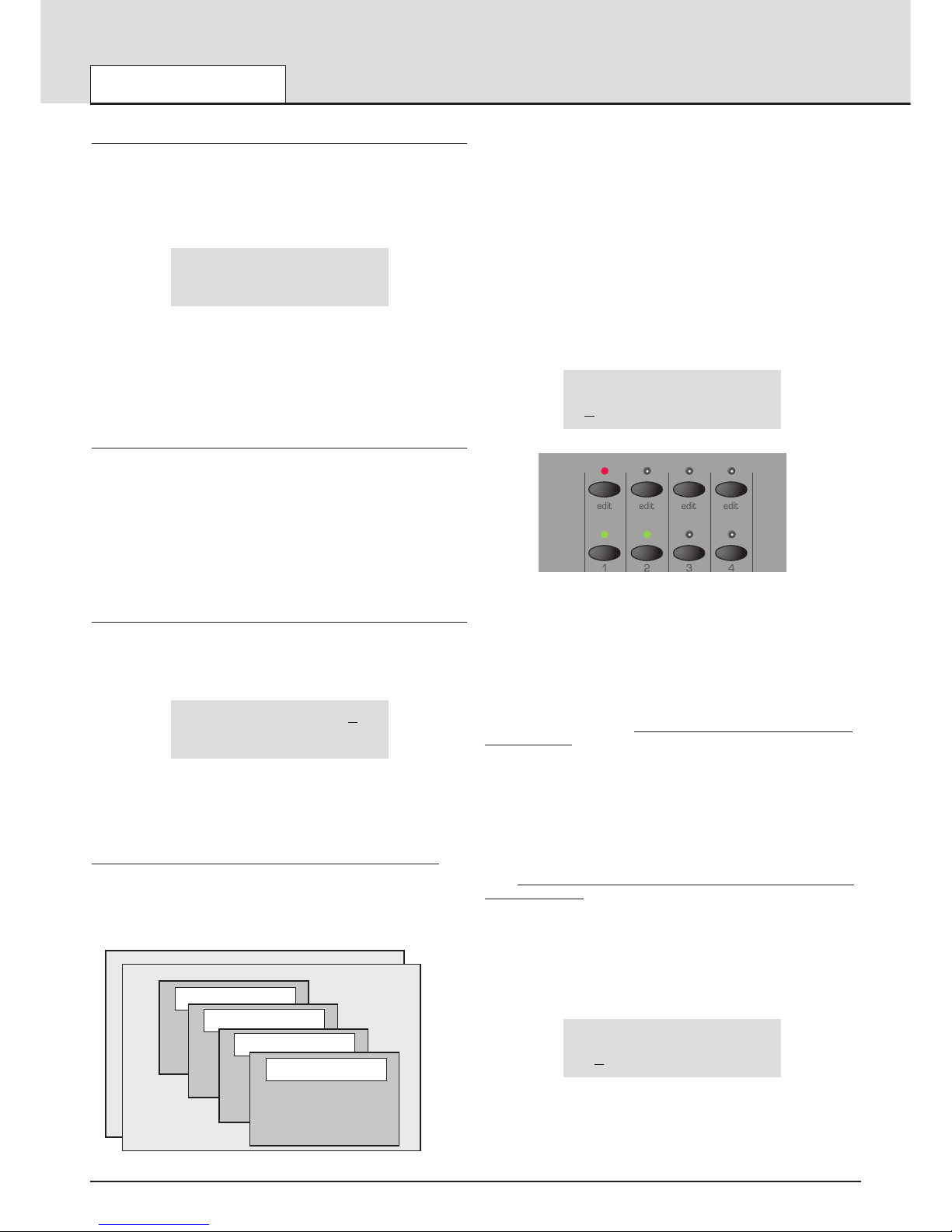
Making an Edit with the front panel Controls in Program Mode
If any of the front panel controls are adjusted, the display will show the
new value of the appropriate control.
If for example, the Filter FREQUENCY knob was adjusted to 100, the
display would show :
Filter frequency 127
90
The number on the bottom line is the current value of the Filter
Frequency. This is the value that is stored in the Program before any
tweaks or edits have taken place.
The number at the top right is the new edited or tweaked value. This feature make is very easy to see how any control or switch was set in the
original program.
‘Pinging’ to new Values
Suppose the Filter FREQUENCY knob is fully clockwise (physically point
ing to the 5 o’clock position) indicating a fully open setting (127).
If the Filter setting of the Program being listened to is actually set to the 2
o’clock position (say 101), a slight movement of the FREQUENCY knob
will result in the sound ‘pinging’ instantly to a brighter sound. This is
because the Filter frequency will jump to a maximum value of 127 represented by the knob’s current physical 5 o’clock position.
The number appearing on the bottom line makes it easy to ‘home in’ on
the original value stored with the Program or Performance.
Making an Edit with the front panel Controls in Performance Mode
Performance Mode is selected by pressing the PERF button. The LED
above the PERF button lights to confirm selection. The standard
Performance Mode screen is displayed.
Performance name 101
123 234 345 456
The cursor is positioned at the Performance number adjacent to the
Performance’s name. (Performances are numbered 100 to 199). At this
position, selection of Performances is achieved in a similar manner to
selecting Programs by means of the Keypad buttons, the PAGE buttons,
or the DATA knob.
The BY
CATEGORY button cannot be used to select Performances.
The four sets of numbers beneath the Performance name refer to the
Program numbers that are held in each of the parts within the
Performance. The illustration below shows the relationship between
Performances, Parts and Programs.
Held in the Performance are 4 part ‘slots’ that may in turn hold any one of
400 single Programs. For versatility, other information such as MIDI channel, note range etc. is also held in each part along with the program number.
This additional information may be edited by pressing the Menu button
under the part level knob - See page 54 for more information on these
parameters.
The SELECT left and right buttons are use to select the Part (where the
Program is held) for editing.
Press the SELECT left button. The cursor will move to the Program number held in Part 1 of the Performance. Subsequent presses of the
SELECT left and right buttons will move to the next Program number
across the bottom line of the display.
Performance name 101
123 234 345 456
The program number underlined is reflected on the front panel by the red
LED being lit. Moving the cursor with the SELECT buttons will also cause
the red LED to move in simpathy. Similarly, pressing a different edit button
in the parts section will cause the cursor to move.
At this time, the KEYPAD buttons, PAGE up / down buttons and DATA
knob may be used to select a new Program number on the selected Part
The BY CATEGORY button may be used to select a Program in the same
way as previously described. T
o return to selecting a Performance, press
the PERF button.
Any control that is moved moved on the front panel is now editing the program that is held in the part of the currently selected performance.
The display will behave in the same way as when editing a single program - See above left.
NOTE: Edits made to Programs that are held in a performance DO NOT
affect the programs that are held in the single program memory areas 100
- 399. There is a complete additional copy of the program held in the part
of the performance.
This powerful feature allows changes to be made to sounds within a performance without having to worry that, if the program is used elsewhere it
will be affected.
If, for example the program on part 1 was edited, the display would look
similar to the following illustration
Performance name*101
*1
23 234 345 456
An asterisk will appear to inform that this program held in this perform-
ance is different is some way to the program in the single program area
numbered 123. Also notice that a further asterisk appears next to the performance number indicating that, it too has changed from the orginal.
MAIN FEATURES AND OPERATION
Modes and Menus
• 20 •
Electric Drums 600
Strings 345
Electric Piano 234
PERFORMANCE 100
PERFORMANCE 101
Bass Guitar 123
Part 1
MIDI Channel 1
Outputs 1 & 2
Volume 99
Semitone offset +12
Cents offset -06
Part 2
Part 3
Part 4
Page 21
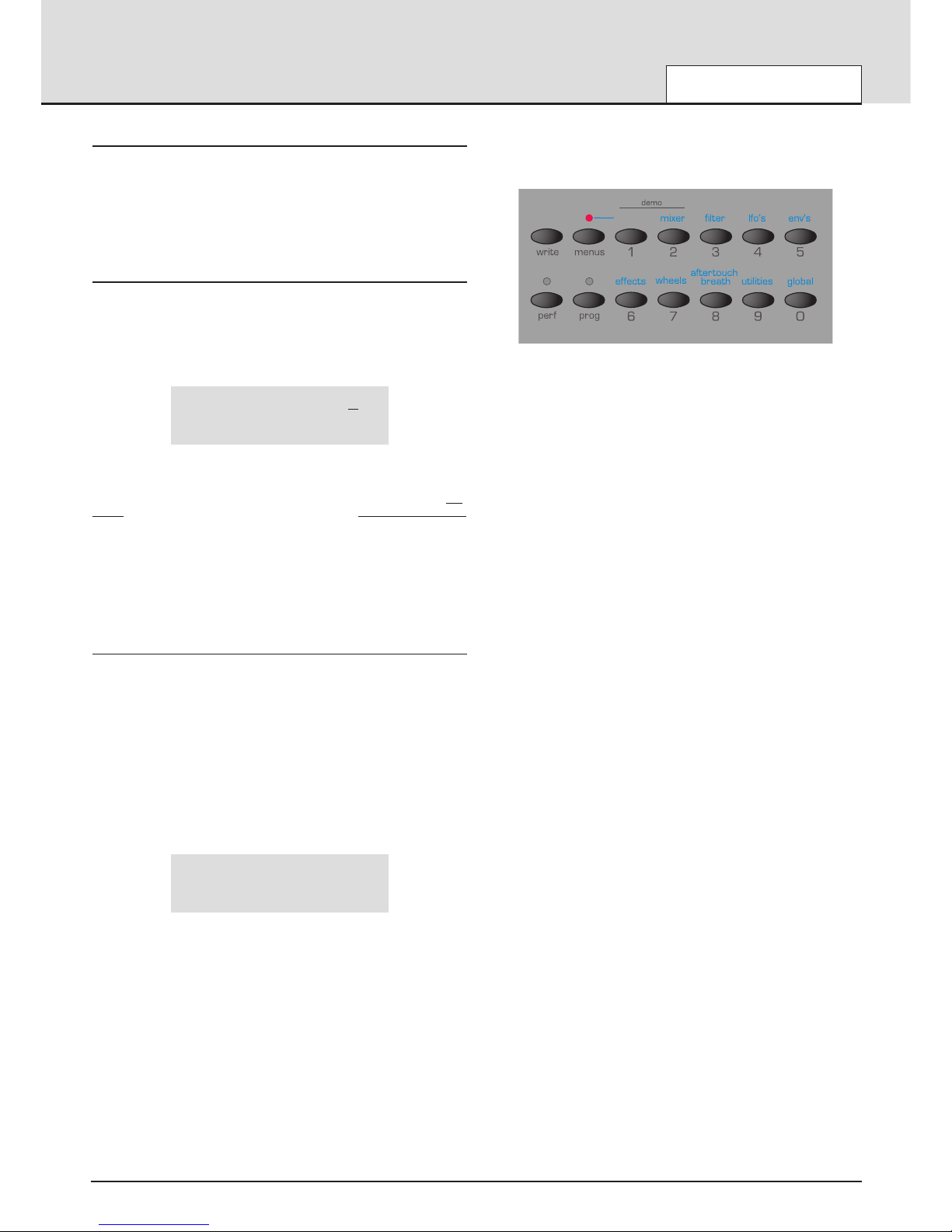
Exporting the edited program out of the performance
Pressing the write button when the cursor is under the program number
will just save the program number to a desired located. The saving prodcedure is detailed on page 8 of the quick start guide section.
This provides a convenient method to EXPORT edited programs out of a
performance back to a single program memory location.
Saving the edited performance
Press the PERF button and the cursor will position itself under the performance number. Press the write button to initiate the saving of the performance. See Page 8.
After saving the performance, the display would appear as below.
Performance name 101
*123 234 345 456
Notice that the asterisk has dissappered from the Performance number
since both the saved performance and the one being listened to are the
same. Alos notice that the asterisk before the program number 123 is still
visible
since the program held is this performance is different in some way
to that held in the single program memort area.
Is possible to make the editing displays permanent (for example when the
Filter knob is adjusted the values will stay on the display permanently until
another conrol is used). It is also possible to vary the time that the displays are shown for. These options are in the Global Menu. See page 51
in the Advanced Features chapter for more details.
Menus
Many of the advanced features and utilities are available from menus.
There are thirteen separate menus, each of which consists of several
pages linked together. Menu pages are accessed by pressing any of the
relevant MENUS button.
When any of the MENUS are activated the LED situated above the
MENUS button is lit. As soon as a Menu is entered, the display will show
the first page of whichever menu was accessed the previous time the
Menu was used.
For example, if the Filter Menu had been previously selected, the display
would show one of the pages of the Filter Menu.
Filter Q norm 13
<<MENU>> 49
Once any of the Menus have been selected, the PERF / PROG / PAGE
buttons to the left of the display are be used to navigate forwards and
backwards between the menu’s pages. Once the desired menu page has
been reached, the values are altered by using the PERF / PROG / DATA
knob.
The display behaves in the same way as when a front panel control is
adjusted. The current value being shown on the botton line and the new
value being shown on the top line. MENU text in capitals is at the left of
the display to inform that a MENU is selected.
When the Main Menus button is selected, as in the following illustration,
different menu may be activated by pressing any of the 0 - 9 keypad buttons.
The ten menus available here are associated with the Oscillators, Mixer,
Filter, LFOs, Envelopes, Effects, Wheels, Aftertouch / Breath Control,
Utilities and the Global parameters.
The Part, Sync and Arpeggiator menus are always selected directly by
pressing the dedicated menu buttons within the appropriate section on
the front panel.
When any menu is selected, the page that first appears may be set using
one of the options in the Global Menu. See page 51 for information on
how to do this.
Once in a Menu it is possible to alter any of the front panel controls as in
Program Mode, but it will be noticed that when a knob is moved, the display text for the knob just moved will only be shown on the screen for a
short period of time. (This time is set using the Function Display time
parameter in the Global Menu - see page 51). After a short time, the display will revert back to showing the current menu page.
It is possible to exit a Menu by pressing the current Menu button again, or
to move to another menu by pressing a different menu button.
If Program Mode, was selected before pressing a menu button, then
Program mode will be selected on exit.
If Performance Mode was selected before presing a menu button, then
Performance Mode will be selected.
It is possible to exit any menus by pressing the PROG or PERF buttons.
MAIN FEATURES AND OPERATION
Modes and Menus
• 21 •
osc's
Page 22
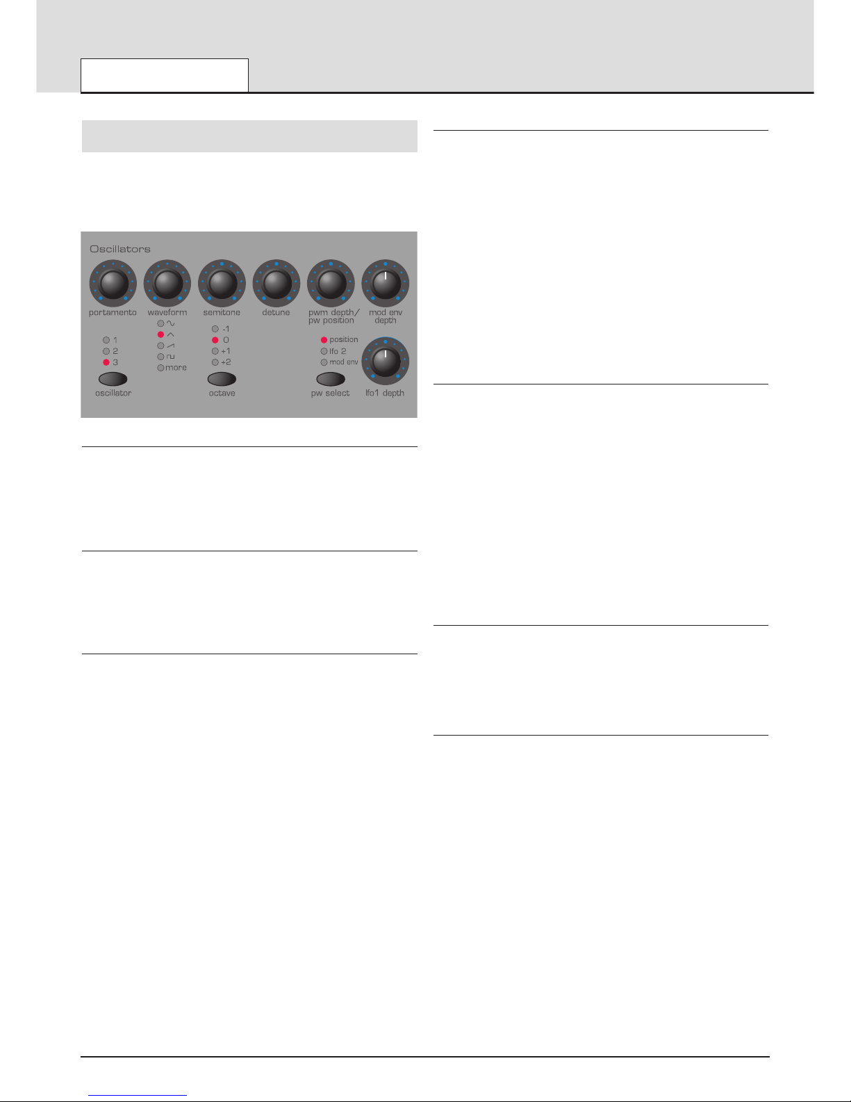
Oscillator Section
The Oscillators generate pitched waveforms (as described in the
Synthesis Tutorial chapter) and these are fed into the Mixer. Most of the
controls which determine the pitch and waveform of the Oscillators, and
how they react to modulation are in this area of the front panel.
OSCILLATOR Select Button
There are three independent Oscillators. Each one can be independently
controlled by the buttons and knobs in the Oscillator area. To make make
the controls active and to see waveform and octave settings for Oscillator
1, press the OSCILLATOR button once or more until LED 1 lights. For
Oscillator 2, press until LED 2 lights and for Oscillator 3 press until LED 3
lights.
OCTAVE Button
Sets the basic pitch of Oscillator 1, 2 or 3 in Octave jumps. To change the
basic pitch of the selected Oscillator to +1 octave for example, repeatedly
press the OCTAVE button until the +1 LED lights.
NOTE: The 0 position corresponds to the pitch of 440Hz when note A
above middle C is played.
PW SELECT Button and PWM DEPTH / PW POSITION Knob
The function of the PWM DEPTH / PW POSITION knob is dependent on
the selection of the PW SELECT button. With the POSITION setting
selected, the PWM DEPTH / PW POSITION knob will manually control
the pulse width of a square waveform (the selected waveform for the
Oscillator must be Square wave for this to happen). In order to understand how the Pulse Width knob affects various waveforms, examples,
using factory presets are used. See the following paragraphs titled:
Obtaining a classic Square/Pulse PWM sound and Obtaining a
Double Saw ‘thick’ detuned sound.
With the PW POSITION knob in the central position, the Pulse Width
wave becomes a square wave. As the knob is adjusted clockwise, or anticlockwise, the Pulse Width becomes narrower producing what is termed
as a Pulse Wave.
With the LFO 2 position selected by the PW SELECT button, the width of
the Pulse Wave may be modulated by LFO 2. The intensity of this modulation is determined by the PWM DEPTH knob. With the Pulse Width
knob at central position there is no effect. Turning clockwise or anticlockwise introduces the effect. Continuous variation in the width of a pulse
waveform (which is what is happening when LFO 2 is modulating it)
changes the harmonic content. This is pleasing to the ear, especially at
lower pitches where all the associated harmonics fall within the audio
range. This creates the classic PWM sound, as described below.
When modulated by the MOD ENV, the effect is most apparent when
using fairly long Mod Env Attack and Decay times.
Obtaining a classic Square / PWM sound
The PWM sound is one of the classsic analogue synthesizer sounds.
Select one of the factory initialisation sounds ( 311 - 499) All of these initial sounds use only use Oscillator 1 as the source waveform. Select a
square waveform using the WAVEFORM button in the Oscillators section.
Notice how the timbre changes to a more ‘woody’ sound. Select POSITION using the PW SELECT button.
Rotate the PWM DEPTH / PW POSITION knob and notice how the sound
changes to a very thin nasal sound when the knob is towards the clockwise or anticlockwise end stop positions. (If fact the sound will extinguish
completely at maximum settings). Leave the knob at the 12 o’clock position.
Select LFO 2 using the PW SELECT button. Slowly rotate the PWM
DEPTH / PW POSITION knob. Notice that there will now be some movement in the sound. Select LFO 2 in the LFO’s section using the LFO button. Rotate the SPEED knob in this section and notice how the speed of
the movement will change. Experiment with the above controls until the
desired sound is achieved.
Obtaining a Double Saw ‘thick’ detuned sound
A thick ‘Double Saw’ detuned sound using just a single Oscillator may be
created easily. If necessary, this sound can be stacked using additional
Oscillators to product a ‘huge’ sound. Select one of the factory initialisation sounds ( 311 - 499). All of these initial sounds use only use Oscillator
1 set to a sawtooth as the source waveform. Select POSITION using the
PW SELECT button.
Rotate the PWM DEPTH / PW POSITION knob fully clockwise. As the
control is rotated, a double sawtooth wave is generated. At this fully clockwise position the pitch will appear to double.
Select LFO 2 using the PW SELECT button. Slowly rotate the PWM
DEPTH / PW POSITION knob. Notice that there will be some movement
in the sound. Select a sawtooth LFO wave using the WAVEFORM button
in the LFOs section. Press the LFO button to select LFO 2. Rotate the
SPEED knob in this section and notice how the speed of the movement
will change. Experiment with the above controls until the desired sound is
achieved.
PORTAMENTO Knob
This knob adjusts the Portamento effect. With this control set to zero,
when the keyboard is played, the pitches of notes change instantly from
one pitch to another as different keyboard notes are played. Turning the
knob clockwise introduces the Portamento effect. Notes will glide smoothly from one pitch to the next. Increasing the amount will slow the time
taken for the pitch of the first note to reach that of the second note played.
WAVEFORM Knob
This knob sets the currently selected Oscillator’s waveform. As the knob
is turned, the WAVEFORM LEDs indicate which waveform is currently
selected. There are 32 waveforms available. The first 4 of these are the
traditional waveform shapes found on classic analogue synthesizers. The
next 4 are special noise types. The remaining 24 are digitally sampled
waveforms that provide useful sources fro emulating more tradional instruments and percussion sounds..
When this knob is at the fully anti-clockwise position, the Sine waveform
is selected. As the knob is turned clockwise, the other traditional waveforms are selected. After these, the more complex harmonic waveforms
are available. Whenever one of these is selected, the MORE LED will be
lit on the front panel.
On the following page is a table of all the Oscillator waveforms available.
MAIN FEATURES AND OPERATION
Oscillator Section
• 22 •
Page 23
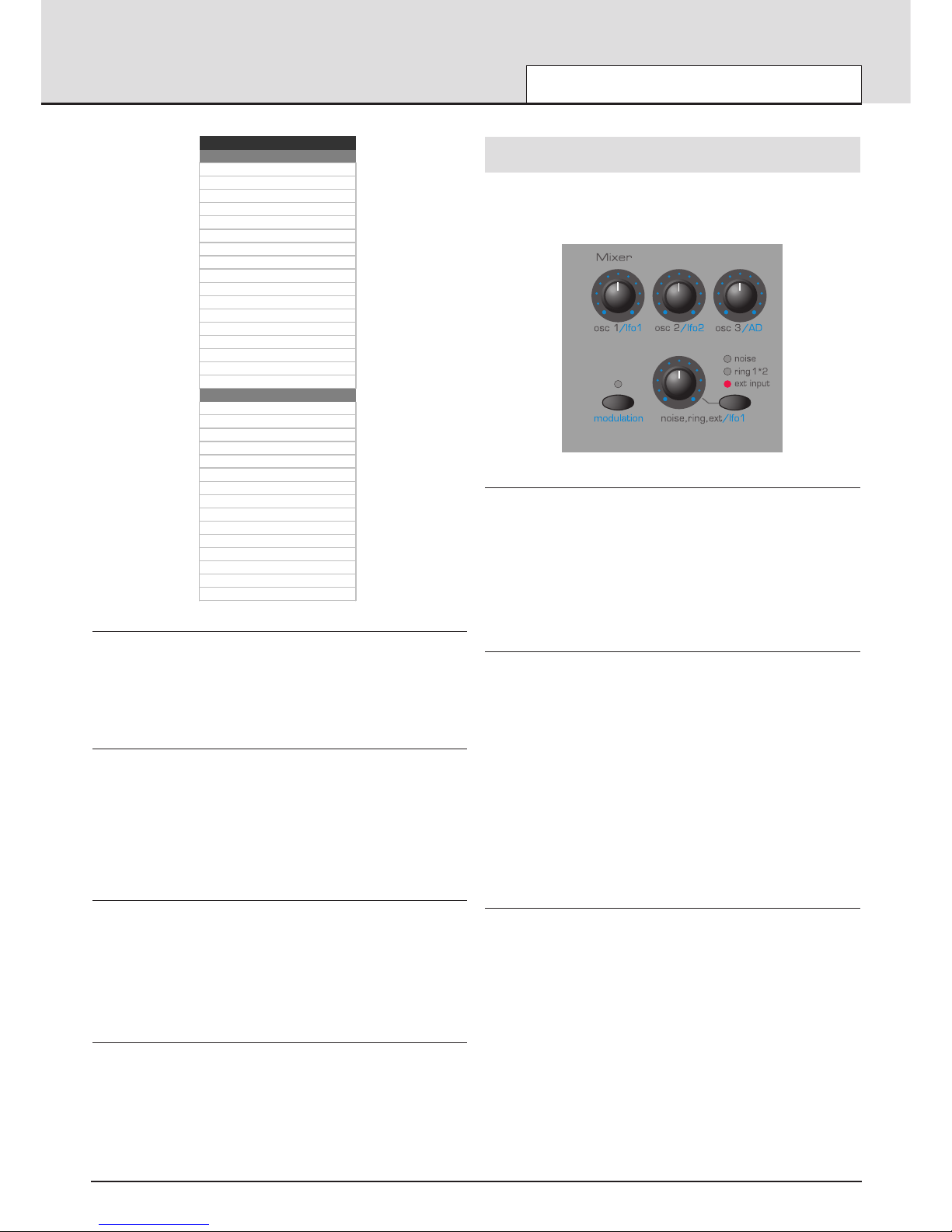
SEMITONE Knob
Raises or lowers the selected Oscillator’s pitch in semitone increments up
to a full octave. Setting the pitch of Oscillator 1 to zero and adjusting the
pitch of Oscillator 2 and 3 by differing amounts results in some musically
pleasing intervals. Settings 5 (a perfect 4th), 7 (a perfect 5th), 3 (minor
3rd), 4 (major 3rd), 8 (minor 6th) and 9 (major 6th) offer the best results.
Use other settings for intentionally discordant sounds.
DETUNE Knob
Sets the detune amount in Cents for the selected Oscillator 1,2 or 3. If it is
set fully clockwise, the Oscillator’s pitch will be 50 cents sharper than its
basic pitch. Fully anticlockwise and it will be 50 cents flat.
Slight detuning between each Oscillator will enrich the sound by introducing a beating between the Oscillators (in the same way a 12-string guitar
sounds richer than a 6-string). Bass and lead sounds can be fattened up
using a small amount of detune. Large amounts of detuning will lead to
more extreme effects.
MOD ENV DEPTH Knob
Controls the amount of pitch modulation to the currently selected
Oscillator from the Mod Envelope. In the centre position there is no effect
on the oscillator's pitch. Anticlockwise the effect is negative (i.e. the pitch
drops and then rises) and clockwise, positive (the pitch rises and then
falls).
See Envelopes Section, on Page 26 for the setting of the rise and fall
times.
LFO 1 DEPTH Knob
Controls the amount of pitch modulation to an Oscillator from LFO 1. It
controls how much above and below the basic pitch the Oscillator regularly rises and falls. If the LFO 1 is set to a Triangle wave and the LFO’s
speed knob is above the centre of its range, this will produce a vibrato
effect. Other effects like a siren or sea gull cry are possible with more
extreme settings.
Other functions associated with the Oscillators can be found in the
Oscillators Menu. See Page 34.
Mixer Section
The Mixer makes it it possible to combine the outputs of Oscillators 1,2
and 3, the Noise source, the Ring modulator and the external Audio Input.
The ability to mix together any or all of these sound sources makes it
easy to create complex timbres.
OSC 1, OSC 2 & OSC 3 Knobs
Normally controls the volumes of the three Oscillators. Fully anticlockwise
results in no signal. In this position and with all the other Mixer levels
turned down, there will be no audio output. Fully clockwise results in full
volume for the appropriate Oscillator.
When the MODULATION LED is lit (see below) these knobs control the
amount of modulation applied to the mixer. In the central position, no
modulation is applied. Turning the knobs clockwise introduces positive
modulation (the mixer levels become louder). Turning the knobs anticlockwise introduces negative modulation (the mixer levels become quieter).
MODULATION Button
This determines how the various knobs in the Mixer Section are used.
When this button is pressed, the LED above the MODULATION button is
lit and each of the Mixer Section knobs control the amount of modulation
applied from the source specified by the knob. The level of Oscillator 1 is
modulated by LFO 1. The level of Oscillator 2 by LFO 2, the level of
Oscillator 3 by the AD Envelope (see page 39 for setting the AD Envelope
parameters) and the level of the Noise / Ring Modulator / External input
also by LFO 1. These modulation assignments are fixed and cannot be
redefined.
Note : The AD Envelope is a special, dedicated Envelope used for FM
synthesis or to control the level of OSC 3 in the Mixer. It should not be
confused with the AMP or MOD Envelopes found on the KS 4 / KS 5 front
panel.
When the MODULATION button LED is not lit, the Mixer section knobs
control the levels of the various signals fed through the Mixer.
NOISE / RING / EXT Button and Knob
The NOISE / RING / EXT button selects which sound source the NOISE /
RING / EXT knob will control.
With the NOISE position selected, it controls volume of the White Noise
Generator. White Noise is useful for creating sound effects such as Wind.
With the RING 1 * 2 position selected, it controls the volume of the Ring
Modulator. Ring Modulation is useful for creating harder Metallic tones.
With the EXT position selected, it controls the volume of an external audio
signal connected to the INPUT socket on the KS 4 / KS 5’s rear panel.
This signal can be processed by the filter, envelopes and effects. An
external audio signal may be a microphone, CD player, guitar etc. With a
little experimentation, quite effective and dramatic changes to the sound
can be produced : Filtering, wah-wah, gating, using the Effects Section for
adding reverb, chorus etc. Experiment !
Note: All three of these sound sources may be used simultaneously and if
so, it may become necessary to reduce the Program Level dB in order to
avoid signal distortion (see page 39).
MAIN FEATURES AND OPERATION
Oscillator Section - Mixer Section
• 23 •
Oscillator Waveforms
No. Description
0 Sine
1 Tri-Angle
2 Sawtooth
3 Square (Pulse)
4 White Noise
5 Hi-Pass Noise
6 Band Pass Noise
7 Hi / Band Pass Noise
8Organ
9 Harpiscord
10 Electric Piano
11 Slap Bass
12 Rhodes Piano
13 Rhodes Tine
14 Whirly EP
15 Clavinet
16 Analogue Bass
Rhythm Sounds
17 Kick 1
18 Kick 2
19 Kick 3
20 Snare 1
21 Snare 2
22 Snare 3
23 Tom Tom (Front)
24 Rimshot
25 Stick
26 Closed Hi-Hat
27 Open Hi-Hat
28 Tamborine
29 Conga
30 Cow Bell
31 Cymbal
Page 24
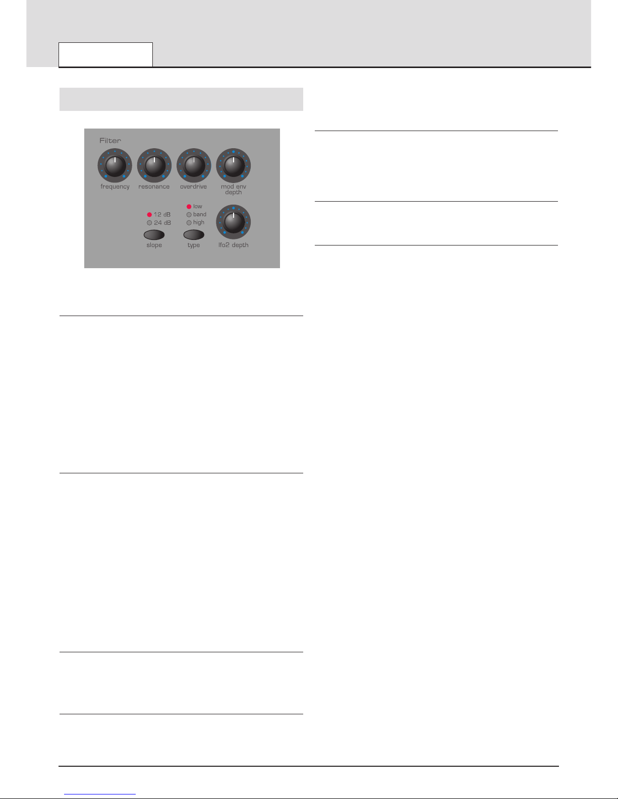
Filter Section
The Filter can be used as a Low Pass, High Pass or Band Pass type.
FREQUENCY Knob
This controls the basic Cut off frequency of the Filter. The Low Pass type
of Filter is the most common type of Filter found on classic analogue synthesizers and is musically the most useful, especially for bass sounds. As
the FREQUENCY knob is adjusted anticlockwise, harmonics are gradually
removed from the sound. When almost closed, only the fundamental frequency remains. Fully closed and no sound at all passes.
With the High Pass Filter type, as the FREQUENCY knob is adjusted
clockwise, harmonics are gradually removed from the sound. When
almost fully anticlockwise, only the fundamental frequency remains. When
Fully clockwise and no sound at all passes.
With the Band Pass Filter type, a narrow band of frequencies are passed,
centered on the position of the FREQUENCY knob. This kind of Filter is
useful when it is desired to pass only a specific frequency present in a
sound.
RESONANCE Knob
This knob controls the Resonance of the Filter. The control will boost frequencies at the Cut off frequency. On on some synthesizers, this control
is known as Emphasis since it will emphasize certain frequencies. At the
zero position there is no effect. Turning clockwise slowly introduces the
emphasis.
Set fully clockwise, the Filter will begin to self - oscillate, producing a new
pitched element (similar to feedback on an electric guitar).
Note : At least a small signal must be fed into the Filter in order for the
resonance to take effect. It is not possible for the filter to self - oscillate if
no signal at all is fed into it.
If the KS 4 / KS 5 produces a high pitched whistling sound, it is probably
due to this knob is being adjusted too far clockwise. If this self-oscillating
effect is not desired, keep the Resonance control away from the extreme
clockwise setting. Increasing the Resonance is very good for bringing out
modulation (movement or change) in the filter Cut off frequency, such as
in Acid bass lines and other very edgy sounds.
OVERDRIVE Knob
This knob controls how much the filter is overdriven. When used in large
amounts it will have the effect of making the sound richer and slightly distorted.
MOD ENV DEPTH Knob
Controls the amount of change to the filter Cut off (set by the FREQUENCY knob) by the Modulation Envelope. In its central position there is no
change to the filter Cut off frequency. Adjusting the knob anticlockwise
from centre will introduce an increasing amount of negative modulation.
The filter will close as the MOD ENV runs through its cycle. Adjusting the
knob clockwise from centre will introduce an increasing amount of posi
tive
modulation. The filter will be opened by the MOD ENV.
SLOPE Button
Controls how drastically the frequencies above (Low Pass), below (High
Pass) or around (Band Pass) the Cut off point are removed from the
sound. When the 12dB position is selected, the Cut off slope is gentle so
higher harmonics are not attenuated (reduced in volume) as sharply as
they are when the 24dB position is selected.
TYPE Button
Determines whether the Filter is acting as a Low Pass, High Pass or Band
Pass type.
LFO 2 DEPTH Knob
Controls the amount of change to the filter Cut off (set by the FREQUENCY knob) by LFO 2. In its central position there is no change to the filter
Cut off frequency. Adjusting the knob anticlockwise from centre will introduce an increasing amount of negative modulation. The Filter will close
and open in time with LFO2 (this creates the popular wow wow effect of
LFO2 wavefrom is set to Triangle).
Adjusting the knob clockwise from centre will introduce an increasing
amount of positive modulation. The filter will open and close in time with
LFO 2.
NOTE : An external audio signal such as a microphone, guitar or CD player may be processed by the filter and effects. Refer to Page 51 in the
Advanced Features Chapter for more details on setting up this feature.
More functions associated with the Filter can be found in the Filter Menu.
See Page 37.
MAIN FEATURES AND OPERATION
Filter Section
• 24 •
Page 25

LFOs Section
There are two LFOs - Low Frequency Oscillators - available on the KS 4 /
KS 5. These produce regular electronic variations which are too low to be
heard when converted into audio vibrations. They can modify various elements of the sound, producing regular changes in pitch (vibrato), pulse
width or filter Cut off.
SPEED Knob
Controls the speed of the selected LFO. An LED directly below the knob
indicates the speed. Faster speeds are set by turning the knob clockwise.
These are suitable for vibrato and tremolo effects. Slower speeds are
more appropriate for Pulse Width changes or special effects.
WAVEFORM Knob
Selects the waveform shape for the selected LFO. As waveforms are
selected, the WAVEFORM LEDs update to reflect the currently selected
waveform and the screen displays the currently selected waveform type.
The first four LFO waveforms are the traditional types commonly found on
classic analogue synthesizers. Additional special waveform types (including rythmic patterns) are also provided as detailed in the table below.
When one of these is selected, the MORE LED will be lit. Experiment !
Sine Wave
Gives the smoothest continuous change in level to the LFO. When routed
to pitch, it introduces vibrato or a siren effect dependent of its speed setting. When routed to Filter Cut off, a Wow Wow effect results.
Triangle Wave
Also gives a smooth change in level to the LFO in a similar manner to the
Sine wave. As its name implies, the Triangle wave does not remain at the
peak of its waveform cycle for as long as the Sine wave. When routed to
pitch, it also introduces vibrato or a siren effect dependent of its speed
setting. When routed to Filter Cut off, a Wow Wow effect results.
Sawtooth Wave
Generates a rising level which then jumps back down to zero level.
Routed to the Filter Cut off, it produces a rhythmic pulse effect. Routing it
to pitch produces siren type sounds.
Square Wave
Changes level instantly from minimum to maximum. Useful for trills and
computer game effects. Very effective when used to modulate Osc Pitch.
Sample and Hold
At a regular interval (governed by the SPEED knob), the level of the LFO
jumps to a new random level and stays there until the next jump. This creates a rhythmic effect, particularly if routed to the Filter Cut off. Routing
this to pitch gives a less musical result, but is useful for computer / random or machinery sound effects. A ‘quantized’ version is also available.
Here, the waveform is either at the top or bottom of its cycle. The effect is
similar to a square wave with an unpredictable pulse width setting.
Cross fade
A single -shot, linear decay from maximum to minimum level. This is useful for implementing crossfades with an LFO used as a modfulator. With a
postive modulation amount, this LFO waveform ‘fades out’ the modulation.
With a negative modulation amount, this LFO waveform ‘fades in’ the
modulation.
Curved Sawtooth
Similar to a standard sawtooth wave, but the waveform slope is in fact an
exponentially decaying curve. When the LFO is used in ONE SHOT mode
as a simple Envelope Generator (see below), a Curved Sawtooth’s
‘decay’ often sounds more pleasing and natural than the straight, linear
‘decay’ of a standard Sawtooth wave.
Pattern trigger Waveforms
The last eight waveforms consist of rythmic trigger patterns. These are
especially effictive when the LFO is synchronised to the internal or external MIDI clock. Experiment with the various patterns available to see
which ones work best for the Program.
DELAY Knob
Controls how long after the note is struck the selected LFO begins to take
effect. Fully anticlockwise and the selected LFO effect will begin immediately. Turning clockwise will cause the LFO effect to fade in. The time of
the fade in is dependent on the knob position. This is used for delayed
vibrato effects.
LFO Select Button
Selects which LFO the SPEED, WAVEFORM, DELAY and ONE SHOT
controls relate to. Select position 1 for LFO 1 and 2 for LFO 2.
ONE SHOT Button
This button makes an LFO play its waveform for only one cycle whenever
a keyboard note is played. An LED above the ONE SHOT button indicates when the currently selected LFO is in One Shot mode.
Normally, the LFOs cycle through their waveform cycles continuously.
Setting an LFO to operate in One Shot mode when it has its SPEED
parameter set to a fairly slow value allows an LFO to be used (in effect)
as a fairly simple Envelope generator. In this case, the SPEED knob controls the duration of any ‘Attack’ and / or ‘Decay’ phases in the ‘Envelope’.
Reversing the polarity of the amount of LFO modulation applied (for
example, from -20 to +20) has the effect of mirroring the LFO waveform
about the horizontal axis so that the ‘Attack’ phase becomes the ‘Decay’
phase and vice versa.
MAIN FEATURES AND OPERATION
LFOs Section
• 25 •
LFO Wave forms
No. Description
0 Sine
1 Tri-Angle
2 Sawtooth
3 Square
4 Sample & Hold
5 Sample & Hold Quantized
6 Cross Fade
7 Fast Attack - Medium Decay Expo Ramp
8 Fa st Attack - Fa st Decay Expo R amp
9 Fa st Attack - Very Fast D ecay Expo Ram p
10 Medium Attack - Fas t Deca y E xp o Ram p
11 Sl ow Attack - Fa st Decay Expo R amp
12 Very Slow Attack - Fast Decay Expo Ram p
13 Fast Attack - Medium Hold - Medium Decay Ramp
14 Fast Attack - Long Hold - Medium Decay Ramp
15 Fast Attack - Longer Hold - Medium Decay Ramp
16 Attack - Fast Decay - Second Decay Ramp
17 Attack - Medium Decay - Second Decay Ramp
18 Attack - long Decay - Second Decay Ram p
19 Blipper
20 Chromatic Up Ramp ( Set Osc LFO am ount to 30)
21 Major Chord As cending
22 Major 7th Chord Ascending
23 Minor 7th Chord Ascending
Rhythm Pater ns
24 Pa ttern 1
25 Pa ttern 2
26 Pa ttern 3
27 Pa ttern 4
28 Pa ttern 5
29 Pa ttern 6
30 Pa ttern 7
31 Pa ttern 8
Page 26

Envelopes Section
AMP and MOD Envelopes
The Envelopes are used to shape a sound throughout its duration. The
AMP Envelope determines the volume of the sound with respect to its
duration.
The MOD Envelope may be used to control other sound elements of the
synthesizer throughout the duration of the sound. It can control Oscillator
Pulse Width, Filter frequency and Oscillator Pitch.
ATTACK Knob / Slider
Sets how quickly the envelope rises to its maximum level when a note is
struck. Fully anticlockwise and this rise time or slope is very fast, less
than half a thousandth of a second (instantaneous to the ear) increasing
exponentially to twenty seconds when fully clockwise. To shorten attack
times, turn this control towards zero and to lengthen attack times, turn this
control towards maximum.
Note : When the attack time is set to Zero, the instantaneous rise time of
the Envelope may produce audible ‘clicks’. This is not a faulty condition
and may be useful for the creation of certain sounds (for example, ‘key
clicks’ on organ simulations). If this is undesirable, increase the Attack
time until the clicks are inaudible.
DECAY Knob / Slider
Sets how quickly the envelope falls to a sustain level after the maximum
level has been reached. Set to zero, this time is about one thousandth of
a second (still instantaneous to the ear ) increasing exponentially to twenty seconds when set to maximum. To shorten decay times, move this control towards zero and to lengthen decay times move this control towards
maximum.
SUSTAIN Knob / Slider
Sets the level at which the envelope remains following the Decay phase,
only while a key is being held on a controller keyboard (or there is a MIDI
Note On command present). When set to zero, the envelope will decay to
zero without being interrupted. As the control is moved towards maximum,
the sustain level increases until, when at maximum, the sustain level is at
its maximum level.
RELEASE Knob / Slider
Sets how quickly the envelope falls from the sustain level to zero once the
note has been released. When set to zero, this time is about one thousandth of a second (instantaneous to the ear) increasing exponentially to
twenty seconds when set to maximum. To shorten release times, move
this control towards zero and to lengthen release times, move this control
towards maximum.
Additional settings associated with the Envelopes can be found within the
Envelopes Menu. See Page 39.
Volume and Keyboard Octave controls
VOLUME Knob
This control adjusts the overall output volume on both the Left and Right
master audio outputs found on the rear panel. It also controls the
Headphone output, also on the rear panel. Using a mixing desk as a comparison, this control can be thought of as the channel volume fader.
Keyboard OCTAVE Buttons
These buttons allow the keyboard to be shifted up or down by a whole
octave. The entire MIDI note range of C-2 to G8 can be accessed.
To return to a mid position where the A above middle C on the keyboard
is 440Hz. Press both the Up and Down OCTAVE buttons simultaneously.
Note : When set to the highest octave setting, the top notes on the keyboard beyond G8 will not trigger or transmit MIDI Note messages
because they will be outside of the note range defined by the MIDI specification.
The Keyboard octave setting is memorized along with all of the other
sound information when a Program or Performance is written to memory.
MAIN FEATURES AND OPERATION
Envelopes Section - Volume and Keyboard Octave controls
• 26 •
Page 27

Effects / Arpeggiator / Hypersync Section
The Effects, Arpeggiator and Hypersync features are grouped together in
one section on the front panel. This is convenient since all of these features can be synchronised together and controlled by the TEMPO knob.
Effects
Seven different Effects which may be used simultaneously are provided.
These effects are saved as an integral part of a sound when writing it to
memory. In Performance Mode, each of the four Parts has its own complete set of Effects settings.
Adding Effects to a sound can dramatically enrich the overall sound texture. Some types of Effect are particularly useful in giving a sound a perceived position in three-dimensional space. Adding such sounds to final
mix of a piece of music gives a much greater sense of ‘depth’.
Each type of Effect has several settings associated with it which give fine
control over how the Effect interacts with a sound. These settings may be
changed using the various Effects menus. See Page 41 in the Advanced
Features section for more details.
Effects SELECT Buttons
These two buttons are used to select which of the seven Effects is currently being edited. The seven types of Effect available are :
Delay
This Effect simulates the echoes which would be heard when a sound is
reflected off of a hard, flat surface such as stone wall. The KS 4 / KS 5
actually incorporates a stereo version of this echoing effect.
To visualize a stereo echo, imagine a sound being produced between two
stone walls. The echoes of the sound would bounce off each wall in turn
until the echoes eventually dies away.
Use the EFFECTS LEVEL knob to introduce the Delay effect.
Reverb
The Reverb Effect simulates the acoustic properties of a room. In everyday life, the materials that a room is made of and its size determine how
sound waves are reflected from the room’s walls. Consider as an example, how different a sound is when heard in bathroom with tiled walls.
Singing in particular can be dramatically improved !
Chorus
This is a swirling, stereo Effect, often useful for ‘fattening up’ a sound, creating an impression that several synthesizers are being played in unison,
rather than just one.
This effect is actually achieved by slightly detuning the sound and adding
it back to the original signal.
A similar, related effect to Chorus is the Phaser. Phasers phase-shift certain frequencies of a sound and add them back to the original signal. This
gives a sound passed through a Phaser, a distinctive swishing quality. At
extreme settings, this can sound similar to jet plane passing overhead!
In the Chorus Menu, it is possible to select whether the KS 4 / KS 5’s
Chorus Effect behaves as a standard Chorus or as a Phaser.
Use the EFFECTS LEVEL knob to introduce the Chorus or Phaser effect.
Distortion
As its name suggests, the Distortion Effect distorts a sound signal.
Imagine how a sound recorded onto tape sounds when it has been
recorded with the record level far too high. Much loved by guitarists, distorted sounds have a very gritty, dirty quality to them. This is especially
effective when applied to aggressive lead sounds.
The Distortion Effect also exaggerates any low-level harmonics present
within the sound. Sounds using a level of RESONANCE in the Filter will
especially benefit from added Distortion.
Use the EFFECTS LEVEL knob to introduce the Distortion effect.
EQ
The EQ (short for Equalization) Effect provides a way of diminishing or
emphasizing a specific frequency range within the final sound. It is in fact,
a form of Filter similar to the one found in the KS 4 / KS 5’s Filter section.
It performs a similar function, but it cuts or boosts certain frequencies.
The actual frequency range which will be cut or boosted is determined by
the EQ Frequency Point (the EQ Frequency setting) which is set within
the Effects Menu. See Page 45 in the Advanced Features chapter for
details on how to set this.
The amount of cut or boost applied will depend on the position of the
Effects LEVEL knob. When set to the 12 o’clock position, no cut or boost
is applied. As the knob is turned anticlockwise from the 12 o’clock position
frequencies below the EQ Frequency point will be boosted and frequencies above the point will be attenuated. As the knob is turned clockwise
from the 12 o’clock position, frequencies above the EQ Frequency will be
boosted and those below attenuated.
In the above example, The EQ Frequency point has been set to 50 and
the EQ LEVEL set to -10. This has the effect of gently boosting the lower
(bass) end of the frequency spectrum and cutting the higher (treble) frequecies.
In this example, the EQ LEVEL has been set to its maximum possible
positive setting of 63. This results in a dramatic boost in the higher (treble)
frequencies and a reduction in lower (bass) frequencies.
MAIN FEATURES AND OPERATION
Effects / Arpeggiator / Hypersync Section
• 27 •
save hyper
20Khz1Khz
EQ Frequency Point
(50)
500hz 5Khz 10hz
Unchanged Volume Level
Volume
Boost
Volume
Cut
EQ Frequency Point
(50)
Unchanged Volume Level
EQ LEVEL set to -10
20Khz1Khz
EQ Frequency Point
(50)
EQ Amount (-63)
500hz 5Khz 10hz
Unchanged Volume Level
Volume
Boost
Volume
Cut
EQ Frequency Point
(50)
Unchanged Volume Level
EQ LEVEL set to +63
Page 28

Panning
The Panning effect dictates where in the stereo field a sound is placed
when heard through stereo speakers or headphones. It is possible to
position a sound hard to the left, hard to the right or anywhere in between.
The Effects LEVEL knob intoduces an amount of panning modulation
which affects the location of the sound in the stereo field. When set fully
counter-clockwise, the sound will only be heard in the position set by the
manual pan control in the first page of the panning menu.
At the fully clockwise position, the sound will be move automatically from
the left to the right-hand side at the rate determined by the panning rate
control found in the Panning Menu.
Vocoder
A Vocoder is a device which analyzes selected frequencies present in an
audio signal (called a Modulator), and superimposes these frequencies
onto another sound (called the Carrier).
It actually does this by feeding the Modulator signal into a bank of band
pass filters. Each of these filters (16 of them on the KS 4 / KS 5) covers a
set band in the audio spectrum from low to high frequencies.
In the KS 4 / KS 5’s Vocoder, a Program (for example a string sound) is
always used as the Carrier. It is routed to another complete set of 16 filters which have the same frequency band settings as the bank of filters
used for the Modulator. Each of the outputs from the 16 band pass filters
in the Modulator bank control the volume of each of filters in the Carrier
bank.
The final character of the vocoded sound will depend greatly upon the
harmonics present in the Carrier Program. Programs very rich in harmonics (for example using Sawtooth Waves) will generally give the best
results.
Typically, the Modulator signal used by a Vocoder would be a human
voice speaking into a microphone. This creates the distinctive robot or
‘talky’ like sounds which have recently returned to popularity and are now
being used more frequently in modern Pop and Dance music.
Bear in mind however, that the Modulator signal need not be restricted to
human speech. Other types of Modulator signal can be used (for example, an electric guitar or drums) and can often give quite unexpected and
interesting results.
Modulator audio signals such as from a microphone or CD should always
be fed into the KS 4 / KS 5’s AUDIO IN socket, located on the rear panel.
The pitch of the final vocoded sound will depend on whatever pitch the
Carrier (currently selected Program) is playing. Notes can either be
played on the KS 4 / KS 5’s keyboard or received via MIDI from an external keyboard or sequencer. These notes must be played simultaneously
while the Modulator signal is present, otherwise the Vocoder effect will not
appear to work.
The Vocoder is activated and balanced by using the Effect LEVEL knob.
When this knob is turned fully counter-clockwise, the Vocoder is disabled.
As the knob is slowly turned clockwise from the full counter-clockwise
position, the Carrier signal will be heard. As the knob is moved towards
the 12 o’clock position, the Carrier signal will diminish and the fully vocoded sound will become more prominent. At the 12 o’clock position, only the
fully vocoded will be heard. The Carrier or Modulator signals will not be
present. As the LEVEL knob is moved clockwise from the 12 o’clock position, more of the raw Modulator signal will be introduced until at the fully
clockwise position, only the Modulator signal will be present.
More settings are available to help shape the final Vocoder Effect. These
are detailed on Page 46 in the Advanced Features chapter.
Note : In Performance Mode, only one Vocoder can be used. In
Performance Mode, this is always routed to Part 1. Altering any vocoder
parameters will always result in Part 1 being affected - even if it is not currently selected for editng.
Note : If either of the Effect SELECT buttons are pressed while the Effects
Menu is active in Menu Mode, the display will be updated to show settings relevant to the newly-selected Effect.
EFFECTS LEVEL Knob
This control’s function depends upon the Effect currently selected for editing by the SELECT buttons. In most cases, it will control the Effect’s level,
but there are exceptions. All possibilities are detailed in the above table.
Arpeggiator
An Arpeggiator breaks down chords into single notes and plays them one
at a time. For example, if a ‘C’ triad chord is held, the notes C, E and G
will play one by one in sequence.
In Performance Mode, each Part can have its own Arpeggiator running
with its own unique settings and time signature. Each Arpeggiator can be
synchronised with the Arpeggiators used by the other Parts.
Which Arpeggiator pattern is used and how the sequence of notes are
played is determined by settings of the functions located in the
Arpeggiator Menu. See Page 54 in the Advanced Features chapter for
more details on these.
TEMPO Knob
This controls the speed at which the Arpeggiator plays back its notes.
When turned fully anticlockwise, the Arpeggiator will step through a
sequence at 64 beats per minute. Clockwise movement increases speed.
The maximum speed available is 191 b.p.m.
Note ; In Performance Mode, there is only one Arpeggiator TEMPO control which is common to all Parts. It is therefore not possible to have different Parts running at different TEMPO speeds.
When the Global MIDI Clock Source value (see Page 50) is set to INT,
this knob also controls the tempo of any synchronized Chorus, Delay,
Panning or EQ effects. See the Hypersync paragraph on page 29 and
the Synchronisation Menu on page 52 for details on how to synchronise
these.
When MIDI Clock Source is set to EXT, the tempo of any synchronized
Arpeggiator, Chorus, Delay, Panning or EQ will be controlled by the tempo
of the external sequencer instead of the TEMPO knob which will have no
effect on the speed.
If this knob appears to have no effect on the tempo, the reason is probably due to MIDI Clock Source being set to EXT or that the external
sequencer is currently stopped (stopped sequencers do not usually transmit MIDI Clock messages).
ARP ON Button
This activates / deactivates the Arpeggiator. While the Arpeggiator is activated, the LED above the button will be lit.
While an arpeggio is running, it can be stopped immediately by either
pressing the ARP ON button again or by pressing the PERF or PROG
buttons.
ARP LATCH Button
This button enables the Arpeggiator Latch feature which enables the
Arpeggiator to remember the last set of notes played on the keyboard.
When latched, the LED above the button is lit. The Arpeggiator sequence
will continue to play even after notes have been released.
Once all notes on the keyboard have been released, the next chord to be
played on the keyboard will clear the existing latch memory and only the
newly played chord will be Arpeggiated.
Note : It is possible to control the Arpeggiator Latch On/Off from an external Computer/Sequencer/Keyboard. Transmit MIDI CC 64 (Sustain) with a
value of 127 to turn the Arpeggiator latch ON and transmit controller number 64 with a value of 0 to turn the latch OFF.
MAIN FEATURES AND OPERATION
Effects / Arpeggiator / Hypersync Section
• 28 •
Effects Level Knob
Effect Select ed Function Display Value
Delay Delay Level Delay Send 0...127
Reverb Reverb Level Reverb Send 0...127
Chorus Chorus Level Chrous Send 0...127
Distortion Distortion Boost Distortion 0...127
EQ EQ Cut/Boost Equalisation -64...63
Panning Mod Depth PAN Mod Depth 0…127
Vocoder Vocoder On/Balance Vocoder Bal 0...127
Page 29

ARP MENU Button
Pressing this button accesses the Arpeggiator Menu. The LED above the
MENUS button in the Mode / Keypad section of the front panel lights to
confirm this. The parameters and features available in the Arpeggiator
Menu are detailed on page 54.
Hypersync
It is possible to synchronise many Effects parameters and other features
such as LFO speed to a common, internal clock or to an external MIDI
clock supplied by a sequencer. Synchronisation of each individual setting
can be achieved by accessing the various parameters via the
Synchronisation Menu. This can be very time consuming so to speed up
the process, 16 editable ‘Hypersync’ templates are available which provide effective, musically synchronized settings.
When selected, a Hypersync template applies synchronisation settings to
four Effects and four Program parameters. Settings for the Delay level,
Chorus Level, Panning Depth and EQ Modulation Depth are also applied
making a total of twelve Hypersync values.
Using tempo synchronized features can significantly enhance music production. The details of the eight values capable of being synchronized to
internal or external MIDI clock are :
Delay
The time period of the Delay Effect is synchronized. The Delay level can
be stored in the Hypersync template.
Chorus / Phaser
The time period of the Chorus / Phaser is synchronized. The Chorus /
Phaser level can be stored in the Hypersync template.
Panning
The Panning time period is Synchronized. The Panning Depth setting can
be stored in the Hypersync template.
EQ / Filter
The EQ / Filter sweep time is synchronized. The Modulation Depth setting
can be stored in the Hypersync template.
LFO 1 & LFO 2
The amount of time taken for an LFO to play a single cycle of its waveform can be synchronized. Each LFO can be synchronized individually.
LFO 1 Delay & LFO 2 Delay
The delay time period for an LFO can be synchronized. Each LFO can be
synchronized individually.
HYPERSYNC Knob
This selects which Hypersync template is applied to the Program (sound).
The display indicates which template is applied when the knob is at nonzero. At the fully counterclockwise position, the Hypersync Menu will deactivate and the normal Progam Mode or Performance Mode display will
be activated.
When no Hypersync template is selected, all of the original parameter values stored in the Program / Performance are restored to the Sync and
Effects settings. The Hypersync ON LED is not lit.
As the HYPERSYNC knob is moved clockwise, each of the sixteen templates are selected in turn. For example :
Hypersync 01
Syncopated Delay
The Hypersync ON LED lights to indicate a Hypersync Template has been
selected. The number on the top line of the display indicates which of the
sixteen templates is selected. For reference, each template is assigned a
name which is shown on the bottom line of the display
When shipped from the factory, the first eight Hypersync templates are
pre-configured.
When the any of these first eight templates are activated the display will
show
Hypersync 01
Preset Table 1
The actual number will depend on the which number is selected. The preset table names may be edited, see the section on the following page,
save hyper
Editing a Hypesync Template
Moving the HYPERSYNC knob displays the next Hypersync Template.
(the program currently selected will change its sounds according to the
Hypersync values). Once the desired Template has been selected, use
the PERF / PROG / PAGE Buttons to access the three Hypersync editing
pages.
Press the PERF / PROG / PAGE Up button. The display shows:
DELY CHOR EQ PAN
1bar 4th 2nd 8th
Here the synchronisation rates of the Delay, Chorus, EQ and Panning
may edited. The cursor indicates which of the four parameters on the
page can be altered with the PERF / PROG / DATA knob.
In the above example, the Chorus Delay sync is selected for editing. The
SELECT Buttons can be used to move the cursor to select a different
parameter for editing.
The tables found on page 52 gives the possible synchronisation settings
for the various Effects. It is also possible to set each parameter to NCH
(no change) or FRN (Free Run) . When set to FRN, the Effect is not synchronised and will run at its own independent tempo.
Pressing the PERF / PROG / PAGE Up button again, shows :
MAIN FEATURES AND OPERATION
Effects / Arpeggiator / Hypersync Section
• 29 •
Page 30

LFO1..DEL LFO2..DEL
2nd 1
6th FRN 2bars
Here the LFO 1 and LFO 2 synchronisation settings may be edited. The
LFO 1 rate and delay settings are the first two entries from left to right.
The LFO 2 rate and delay settings are third and fourth entries.
In the above example, the LFO 1 delay sync is selected for editing with
the PERF / PROG / DATA knob. The SELECT Buttons can be used to
move the cursor to select a different parameter for editing.
The table found on page 52 gives the possible synchronisation settings
for the LFOs. It is also possible to set each parameter to NCH (no
change) or FRN (Free Run) . When set to FRN, the Effect is not synchronised and will run at its own independent tempo.
Pressing the PERF / PROG / PAGE Up button again, shows :
DELY CHOR EQ_D PAN
93 127 +63 NCH
Here the Delay Level, Chorus Level, EQ Modulation Depth and Panning
Modulation Depth can be edited. In the above example, the Chorus Level
is selected for editing with the PERF / PROG / DATA knob. The SELECT
Buttons can be used to move the cursor to select a different parameter for
editing.
It is also possible to set each parameter to NCH (no change).
Note: If a different Hypersync template is selected before the current template has been written to memory, any edits made will be lost.
SAVE HYPER Button
Pressing this button writes an edited Hypersync template into memory.
The LED above the button indicates whether any edits have been made
to the currently seleccted template.
When the button is pressed, the display shows :
Write to ? 01
Syncopated Delay
The display will now show the destination memory number where the
Hypersync template is about to be saved to. In this example, Write to 01.
Notice that the destination memory is initially set to the currently selected
Hypersync Template’s number. It is possible to save a Template to a different memory location. Use the PERF / PROG / DATA knob or Keypad
buttons to select a different destination memory if required.
Any of the sixteen available Hypersync Template memories can be selected. Press the SAVE HYPER button again to proceed. The display shows :
Name Hypersync 01
‘Syncopated Delay’
On this display it is possible to edit the Template’s name. Use the Left and
Right SELECT buttons to move the cursor within the Template’s name
text. Use the PERF / PROG / DATA knob to select the character located
at the cursor.
Once the name has been entered, press the SAVE HYPER button once
again to write the Hypersync template to memory.
During the saving procedure, saving can be abandoned at any point by
pressing the PERF or PROG buttons. Program Mode or Performance
Mode is selected without
saving the Hypersync Template.
NOTE: When shipped from the factory, the global memory protect switch
is set to on. The memory protect switch is a safety feature designed to
prevent memories from being overwritten by accident. Therefore, in order
to save a Hypersync Template, the global memory protect must be
switched off. See page 6 for details on how to do this.
As soon as the Hypersync Template is saved to memory, the display will
revert back to the display showing the name and number of the
Hypersync Template.
Saving a Program after Hypersync has been applied
Once a Hypersync template has been applied to a Program, the audible
effects to the sound will be noticed immediately. If these settings are
required permanently, the Program must be saved in the normal way. To
do this refer to Page 6 - Saving a Program. If they are not permanently
required, it is only necessary to reload the Program to restore the orginal
sound or return the Hypersync knob to the zero position.
Once the Program has been saved, applying the same Hypersync
Template setting to it will naturally have no effect. If desired the Hypersync
Template may be edited such that an entirely new set of setting will be
introducded when Hypersync is applied.
SYNC MENU Button
Pressing this button accesses the Synchronisation Menu. The parameters
and features available in the Synchronisation Menu are detailed on page
52.
MAIN FEATURES AND OPERATION
Effects / Arpeggiator / Hypersync Section
• 30 •
Page 31

Part Edit Section
MAIN FEATURES AND OPERATION
• 31 •
Part Edit Section
This section contains all the controls associated with configuring the individual Parts when used in Performance Mode. In Program Mode, these
controls are still available for use, but behave as if only one Part is available - Part 1.
PART LEVEL Knob
Sets the currently selected Part(s) volume level. This allows the correct
balance between individual Parts in a Performance to be achieved. In
Program Mode, this knob will only affect Part 1.
Part EDIT Buttons
These four buttons determine which Part will be edited by the front panel
controls. In Program Mode, Part 1 is always selected for editing and cannot be de-selected.
In Performance Mode, any of the four Parts can be selected for editing .
The status of the Part EDIT buttons determine which of the parts will play
when using the keyboard.
If a Performance is configured for a layered type sound (parts are set to
use the same MIDI channels), the keyboard will only play ALL the parts
whose MIDI channels match the channel used by the part that is currently
selected by the EDIT button. In this way the complete layered sound (that
may be a multiple of many parts) may be auditioned.
By switching on and off the parts (pressing the buttons below the green
LEDs) each individual part may by auditioned.
If a Performance is configured multi-timbrally (parts are set to use different MIDI channels), the keyboard will only play the part currently selected
by the EDIT buttons. It would generally be undesirable to audition a collection of parts that contain differnet sounds all at once.
Multi-timbral Performances are for use with an external sequencer such
that different sounds on different MIDI channels can be triggered throughout a song.
Part MENU Button
Pressing this button accesses the Part Menu. The LED above the
MENUS button lights to confirm this. The parameters and features available in the Part Menu are detailed on page 55.
Part Active Buttons
These four buttons determine which Parts are in use.
In Program Mode, Part 1 is always active and cannot be de-activated. No
other part can be activated since a single sound only can be played.
In Performance Mode, any combination of the four Parts can be used by
a Performance. The LEDs above the Part Active buttons indicate which
Parts are currently active. An inactive Part will not respond to incoming
MIDI messages or can be played by the keyboard. An inactive Part can
-
not be edited.
The Part Active buttons also provide a convenient way of ‘muting’
individual Parts on the fly in a live performance situation. Inactive Parts
are in effect, ‘muted’ and do not sound or respond to MIDI messages.
Activating a ‘muted’ Part restores normal operation where it can resume
playing or responding to MIDI.
Page 32

MAIN FEATURES AND OPERATION
Display and Data Entry Section
• 32 •
Display and Data Entry Section
As well as containing the display, this section also contains controls,
whose function varies according to which mode the KS 4 / KS 5 is currently in. For more information on modes, refer to the section Modes and
Menus on Page 19.
PERF / PROG / PAGE Buttons
While in Program Mode or Performance Mode, these buttons may be
used to advance / decrease the currently selected Program /
Performance. If pressed and held down, the Programs or Performances
will start advancing / decreasing in steps of ten Programs at a time.
While in a Menu, these buttons are used to move up and down through
the various linked pages within the currently selected menu.
PERF / PROG / DATA Knob
In Program Mode or Performance Mode, this knob may be used to step
forwards or backwards through the available Programs or Performances.
The interval used in stepping through the Programs or Performances is
determined by how quickly the knob is turned.
In a Menu, this knob is used to adjust the value of the function relevant to
the currently selected Menu Page.
BY CATEGORY Button
Pressing this button enables the category search feature. When category
searching is enabled, the LED above this button is lit and the PERF /
PROG / DATA knob will only search for Programs within the currently
selected category. See page 4 for details on how to select categories and
how category searching operates.
Category searching cannot be used to select Performances.
Left and Right SELECT Buttons
Sometimes within menus and on the Performance Mode display, several
parameters are available for editing on the same display screen. These
buttons are used to move the cursor to a different parameter on-screen.
The PERF / PROG / DATA Knob can now be used to adjust the newlyselected parameter.
DRUM EDIT Button
This button is selects a Drum Map at any time. Once in a Drum Map,
holding this button down and pressing a key on the keyboard will selected
the Drum sound for editing on the front panel.
Using this button is equivalent to selecting the Program in a Drum Map by
the conventional means of using the PERF / PROG / PAGE buttons,
PERF / PROG / DATA knob or numeric keypad buttons, but provides a
convenient, direct shortcut to the appropriate Drum Program in Program
Mode or Performance Mode.
COMPARE Button
While this button is held down, the currently selected Program (if in
Program Mode) or Part (if in Performance Mode) will be recalled from its
original memory location, temporarily losing any edits that have bee made
to the Program since it was originally selected.
Releasing the button restores the edit-buffer, bringing back any changes
made to the Program since it was originally selected. In Performance
Mode, any part selected for editing with the EDIT buttons is compared.
During the process of saving a Program or Performance to a memory
location, the COMPARE button compares the current Program /
Performance against the destination memory as specified in the saving
procedure (see pages 6 and 8).
When saving a Performance, it is the whole Performance at the destination which is compared, not just the currently selected Part(s).
Displaying a Program / Performance Edit
When playing is useful to know whether the current selected sound or
Performance has been modified in any way from the originally saved settings.
If any changes have been made to a Program, (a knob has been tweaked
or a button has selected a different function) an asterisk will appear in the
display soon after the tweak or button press has been made. It will appear
immediately to the left of the Program number when in Program Mode.
Edited program *123
If the change is reversed (the control returned to its position as defined by
the original Program), the asterisk will disappear.
Edited program 123
If a change has been made to a Performance or Part Program, the same
applies. This is how the Performance Mode screen would appear if
edits had been made to the Programs in Parts 2 and 4.
Edited perf *123
123 *234 345 *456
Page 33

MAIN FEATURES AND OPERATION
Mode and Keypad Section
• 33 •
Mode and Keypad Section
This section contains buttons associated with Mode selection, writing
Programs and Performances to memory and selecting Programs or
Performances directly by three-digit entry.
WRITE Button
Pressing this button starts the procedure for saving Programs or
Performances into memory. The procedure for saving Programs is
detailed in the section Saving a Sound on page 6. The procedure for
saving whole Performances or Part Programs is detailed in the section
Saving a Performance on page 8.
If however, this button is pressed while the Global Menu is currently active
in a Menu, instead of saving the currently edited Program, the current settings of all Global parameters will be saved into memory. (The display will
briefly show ‘GLOBALS SAVED’). The next time the machine is switched
on, these values will be remembered.
MENUS Button
Pressing this button selects a Menu. The LED located above the MENUS
button will be lit. If already in a Menu when the button was originally
pressed, the Menu will be cancelled and Program Mode will be selected
(if currently in Program Mode) or Performance Mode (if currently in
Performance Mode).
From a Menu, Program Mode may be also be selected at any time by
pressing the PROG button or Performance Mode selected by pressing
the PERF button.
PERF Button
Pressing this button selects Performance Mode and the LED above the
PERF button lights.
In Performance Mode, a new Performance may be selected by either the
PERF / PROG / PAGE buttons, the PERF / PROG / DATA knob or by typing in a three digit entry by using the 0 - 9 keypad / Menu Select buttons.
PROG Button
Pressing this button selects Program Mode. The LED above the PROG
button lights..
In Program Mode, a new Program may be selected by either the PERF /
PROG / PAGE buttons, the PERF / PROG / DATA knob or by typing in a
three digit entry by using the 0 - 9 keypad / Menu Select buttons.
0 - 9 Keypad / Menu Select Buttons
In a Menu, these buttons may be used to switch to a different Menu.
At all other times, pressing one of these buttons will initiate Program
Mode or Performance Mode. A three-digit entry must be entered so that
the appropriate Program or Performance may be recalled from memory.
For this reason, it is important to make sure that the MENUS button has
already been pressed before using these buttons to select a different
Menu.
osc's
Page 34

ADVANCED FEATURES
The Oscillator Menu
• 34 •
This chapter details the many advanced features available. Most of these
are found in the various Menus available. See page 19 for details on
selecting Menu Mode.
Each of the various Menus available will now be presented in more
detail.
The Oscillator Menu
To complement the front panel controls in the Oscillator section, there are
many other functions located in the Oscillators Menu. This Menu is
selected by pressing the keypad ‘1’ button when the MENUS button in
next to keypad button one is active. Use the PERF / PROG / PAGE
up/down buttons to scroll through the Menu functions available - See
table below.
Polyphony Mode (Menu Page 1)
This setting determines if the Program plays polyphonically or monophonically.
When set to MONO or MONO AG, the Program plays monophonically (ie
only one note can be sounded at any one time). If a chord is played on
the keyboard, it will be noticed that as each individual note is released,
the note sounding will revert back to the nearest played note.
The MONO AG setting enables ‘Auto glide’ (portamento) to be triggered
whenever a note is played on the keyboard before the previously held
down note has been released (legato playing). Using ‘Auto glide’ in this
way can greatly add expressiveness to a Program. It is especially effective when applied to lead type sounds.
The monophonic settings are often useful when replicating sounds in the
‘real world’ which would normally be played monophonically, for example
a bass guitar.
As their name implies, the POLY 1 and POLY 2 settings allow polyphonic
operation.
POLY1 allows successive playing of the same note(s) to be ‘stacked’
together, gradually producing a louder sound texture as the note(s) are
repeatedly played.
With POLY2, if the same note(s) are played repeatedly, they will use the
same synthesizer voices as used previously, thus avoiding the ‘stacked
note’ effect.
Unison Voices (Menu Page 2)
Unison allows more than one voice to be used for each note played on
the keyboard. This effect is useful when a very thick sound is required.
Up to eight voices may layered one on top of another when just a single
note is played.
To listen to the effect, select Page 2 in the Oscillator Menu, turn the
PERF / PROG / DATA knob clockwise until the display shows 2. Play a
note and listen to the sound. It will become thicker sounding. Increasing
the number of notes to a maximum of 8 will result in very dense sounding textures.
Note: As more voices are assigned to Unison, the available polyphony
for all Parts will reduce accordingly. For example, using 8 voices in
Unison mode will result in just two notes of polyphony being available!
Unison Detune (Menu Page 3)
Unison Detune is used in conjunction with Unison Voices as described
above. When using more than one voice per note, the Unison detune
amount sets how much each voice is detuned relative to the others.
Adjust the amount until the desired effect is heard.
VCO Drift (Menu Page 4)
Controls the amount of tuning drift for the Oscillators. Setting a modest
value, 10 for example will cause each Oscillator to slowly drift fractionally
out of tune. Classic Analogue Synthesizers were known to gradually go
out of tune as the internal circuits heated up. This ‘instability’ actually
helped to give them their own unique character!
Preglide Semitones (Menu Page 5)
A Preglide is applied to the pitch of the Oscillators starting at a pitch
determined by the Preglide amount in semitones. Gliding up from a pitch
occurs when the display indicates between -12 to -1, and gliding down
from a pitch occurs when the display indicates between 1 to 12. At a setting of 0, no preglide is applied.
The time it takes to complete the Glide is determined by the PORTAMENTO knob on the front panel. The Preglide is triggered with every
note received.
Portamento Mode (Menu Page 6)
Determines the type of curve applied when PORTAMENTO is used. Two
types of curve are available, Exponential and Linear. Linear Portamento
sweeps through note intervals at a constant rate. When Exponential
Portamento is used, the rate of sweep decreases throughout the note
sweep’s duration.
Start Phase (Menu Page 7)
When synthesizing percussive or plucked type sounds, there is a lot of
detailed waveform information at the beginning of the sound. It is often
useful to have the Oscillator wave start in exactly the same place every
time a key is pressed.
The start phase option allows the precise starting point of the Oscillator
wave to be determined. At a setting of 0, the wave will start at zero
Degrees. Each increment on the display shifts the start point of the wave
approximately 3 degrees. The wave will start at a random phase when
set to OFF.
Osc 1 - 2 Sync (Menu Page 8)
This function provides a way of producing interesting, piercing, metallic
sounds. It does this by using the frequency of Oscillator 1 to periodically
restart the waveform used by Oscillator 2. This technique is known as
Oscillator Sync. Set this to ON to activate Sync.
It should be remembered that the frequency of a waveform corresponds
to the number of waveform peaks (cycles) over a given period of time.
The frequency also determines the Oscillator’s pitch.
Therefore if Oscillators 1 and 2 are detuned from each other, Oscillator
2’s waveform will be periodically interrupted and started again from the
beginning of the waveform cycle every time Oscillator 1’s waveform
begins a new cycle.
The diagram on the following page illustrates this.
Oscillat or Menu
Page Function Display Value
1 Polyphony Mode OSC P ol Mode MONO…POLY 2
2 Unison Voices OSC Unison OFF…8
3 Unison Detune OSC Uni Dtune 0…127
4 VCO Drift OSC Vco Drift 0…127
5 Preglide Semitones OSC Pr eglide -12…12
6 Portamento Mode OSC Porta Mode EXP-LIN
7 Start P hase OSC Start Phase OFF 0..127
8 Osc 1 - 2 Sync OSC 1> 2 Sync OFF-ON
9 Osc 2 - 3 FM Manual Level OSC 23 FM Level 0…127
10 Osc 2 - 3 FM Env Amt OSC 2>3 FM ADEnv -64…63
11 Osc 2 - 3 FM LFO1 OSC 2>3 FM Lfo 1 -64…63
12 Osc Fixe d Note Re play OSC Fixed Note 0…127
Voice mode
Display Function
MONO Mono No Auto Glide
MONO AG Mono with Autoglide
POLY 1 Normal Poly Mode
POLY 2 Poly - no note layering
Page 35

ADVANCED FEATURES
The Oscillator Menu
• 35 •
It can be seen that the resulting synced waveform has subsequently
been modified into a different shape. Altering a waveform’s shape in this
way introduces new harmonics into the sound which gives the resulting
waveform its distinctive synced sound qualities.
It should be realised that the greater the difference in tuning between the
Oscillator waveforms, the more pronounced the sync effect will become,
since more drastic changes will be made to the final synced waveform.
Changing the pitch of one of the Oscillators during the duration of a note
(for example, modulated by an LFO) will add a dynamic quality to the
synced sound.
FM Synthesis
The next two menu options allow sounds based on FM (Frequency
Modulation) synthesis to be created. Before looking at the operations of
these controls, a little explanation of FM synthesis follows.
Earlier in this manual, the basics of subtractive synthesis were introduced. Terms such as harmonics, timbre, waveforms and oscillators
became familiar.
FM Synthesis is the technique of using one waveform to Frequency
Modulate - FM- another to produce a resultant more harmonically complex waveform.
The following diagram illustrates that the higher the modulation between
the Modulating wave and the Carrier wave, the more the waveform
changes.
In the illustration, the Oscillators are producing Sine waves. It is the
change in harmonics over time that makes a sound interesting to our
ears.
In FM synthesis, an envelope generator is inserted between the modulator and carrier waveforms so that there is control over of how much of the
frequency modulation is taking place with respect to time. Adding this
envelope constructs the basic FM building block as shown in the nex
illustration.
It can be seen that the output waveform begins, being identical to the
carrier, but becomes more complex (harmonics are added) as the amount
of FM modulation increases via the envelope. It then returns to a simple
wave again as the envelope decays.
The timbre of the Waveform is changing with time. This is the opposite of
subtractive synthesis where a low pass Filter is used to remove harmon-
ics.
To complete a simple synthesizer, a further envelope is added to control
the output volume.
The complete FM building block is illustrated below.
OSC 2 is able to FM OSC 3 via a dedicated FM envelope. It is important
that it is realized that this Envelope is used only for FM purposes and is
not one of the Envelopes available on the front panel.
The diagram below shows in block diagram format how the KS 4 / KS 5
can produce FM sounds.
The easiest way to be totally familiar with FM is to take one of the factory
preset FM sounds, for example Bank 2 - 09 (Sound 209), a bell sound
and to experiment by modifying the various FM settings.
osc 1- modulator
osc 3- carrier
output waveform
modulation level = 0 = 30
= 90
Modulator Oscillator
Modulation Level = 0
Carrier Oscillator
Output Waveform
= 30
= 90
osc 1- modulator
osc 3- carrier
output waveform
envelope
modulation
level = 20
Modulator
Envelope Modulation = 20
Carrier
Output Waveform
modulator
env - used to
control FM
modulation
amount
env - used to
control amplitude
of sound over
time
carrier
Modulator
Carrier
Envelope used
to control FM
Modulation
amount
Envelope used
to control
Amplitude
Osc 3
Operator 1
Operator 2
Osc 2
FM Env
Amp Env
OSC 2
OSC 3
FM Envelope
AMP Envelope
Oscillator 1
Oscillator 2
Synced waveform
Page 36

ADVANCED FEATURES
The Oscillator Menu
• 36 •
OSC 2 - 3 FM Manual Level (Menu Page 9)
Controls the amount that Oscillator 3 is directly Frequency Modulated by
Oscillator 2. Whilst playing a note, adjust this value by using the PERF /
PROG / DATA knob. Notice that increasing amounts of modulation level
make the sound more metallic.
OSC 2 - 3 FM Amount from AD envelope (Menu Page 10)
Many sounds have complex harmonic movements at the start of the
sound. Introducing envelope modulation with a fast attack and decay time
to control the FM amount will simulate this fast changing harmonic effect.
There is an additional envelope located - See below - that can be applied
to control the FM amount between the oscillators 2 and 3.
The amount of modulation from the envelope can be adjusted by using
the DATA knob. Notice how the ‘spit’ at the beginning of the sound may
be accentuated. Experiment with Oscillator 2’s pitch using the OCTAVE
button and the SEMITONE and DETUNE knobs.
Adjusting the AD Envelope Attack and Decay Times
Changing the AD Envelope attack and decay times (which is used as the
FM modulation envelope) is done from within the Envelopes Menu. See
Page 39 for details.
OSC 2 - 3 FM Amount from LFO 1 (Menu Page 11)
Allows the FM amount between Oscillators 2 and 3 to be modulated by
LFO 1.
Osc Fixed Note Replay (Menu Page 12)
Rather than playing chromatically across the keyboard (as is the usual
case), a sound may be set to just play a fixed note - pitch - when ANY
note is palyed from the Keyboard or when triggered from an incoming
MIDI note on event.
This feature mostly used for sounds that are in the Drum Map.
Experiment by selecting the Drum Map (pressing the DRUM EDIT button),
selecting a Drum sound for edit (Hold down the DRUM EDIT button and
play a key on the keyboard) and selecting page12 in the OSCs Menu.
Use the DATA knob to change the pitch of the sound. If desired, save the
sound in the normal way.
By using this feature on Drum sounds, new interesting timbres may be
achieved.
Page 37

ADVANCED FEATURES
The Mixer Menu - The Filter Menu
• 37 •
The Mixer Menu
T
o complement the front panel controls in the Mixer section, there are
other functions located within the Mixer Menu. This is selected by pressing the keypad ‘2’ button while in a Menu.
Use the PERF / PROG / PAGE up/down buttons to scroll through the
Menu functions available - See table below.
LFO 2 Level Modulation to OSC1
LFO2 may be routed to control the level of the volume from Oscillator 2 in
the Mixer section. This is useful if timbre from OSC to be faded in and
out on a once only basis (LFO2 set to one-shot mode) or cyclically. Listen
to some of the factory presets to hear this function.
Noise
This setting determines the frequency characteristics of the Noise signal
available from the Mixer’s NOISE / RING / EXT knob. Four different types
of Noise are available.
0 - This is standard White Noise, with all frequencies present in equal
amounts.
1 - This is a high pass filtered Noise and is useful for contructing certain
types of percussion type sounds.
2 - This is a band pass filtered Noise and is also useful for contructing
certain types of percussion type sounds.
3 - This is different type of high pass filtered Noise and again it is useful
for contructing certain types of percussion type sounds.
The Filter Menu
To complement the front panel controls in the Filter section, there are
other functions located within the Filter Menu. This is selected by pressing the keypad ‘3’ button while the KS 4 / KS 5 is in Menu Mode.
Use the PERF / PROG / PAGE up/down buttons to scroll through the
Menu functions available - See table below.
Tracking (Menu Page 1)
This controls the amount of change to the filter Cut off (set by the FREQUENCY knob) by the pitch of the note played. When the PERF / PROG
/ DATA knob is turned fully anticlockwise, there is no change to the filter
Cut off frequency. With clockwise movement there will be an increasing
amount of modulation. The filter will be opened more as higher notes are
played on the keyboard. This control is used to define how the timbre of a
sound changes over the keyboard.
At the fully clockwise position, the filter tracks the pitch changes in a 1 to
1 ratio. This means that with RESONANCE set to a high level, the pitch
of the Filter’s self - oscillation will increase in semitone steps as notes are
played on the keyboard. This effect is akin to adding an extra (Sine
Wave) Oscillator to the sound when notes are played on the keyboard.
Velocity Sensitivity (Menu Page 2)
This setting is used to modulate the Cutoff FREQUENCY of the Filter up
or down in response to the velocity information present in incoming note
messages or notes played on the keyboard.
Set in the range -1 to -64, the Filter will close (the Cutoff FREQUENCY
will decrease) as velocity data is applied. With a range of 1 to 63, the
Filter will open (the Cutoff FREQUENCY will increase) as velocity data is
applied. Greater values will open (increase the Cutoff FREQUENCY) as
velocity data is received. At a setting of 0, note velocity will have no
effect.
Q Normalise (Menu Page 3)
This value controls the Resonance Normalise. At zero, when resonance
is applied, the main audio signal will remain at normal levels. Adjusting
clockwise will reduce the signal level in relation to the resonance level.
This feature enables the Filter to emulate many of the classic Filters such
as the Moog type, Oberheim type and Roland TB303* type.
* Trademark of the ROland Corporation of Japan
Filter Menu
Page Function Display Value
1 Tracking FILT Kbd Track 0…127
2 Velocity Sensitivity FILT Velocity 0…127
3 Q Normalise FILT Q Normalise 0…127
Mixer Menu
Page Function Display Value
1 LFO2 Level Mod to OSC 1 MIX Osc1 L2 Lev -64...63
2 Noise Type Mix Noise Type White - Band
Page 38

ADVANCED FEATURES
The LFOs Menu
• 38 •
The LFO Menu
To complement the front panel controls in the LFO section, there are
many other functions located within the LFOs Menu. This is selected by
pressing the keypad ‘4’ button while the MENUS buttons is active.
Use the PERF / PROG / PAGE up/down buttons to scroll through the
Menu functions available - See table below.
LFO Velocity (Menu Pages 1 & 7)
The intensity of the LFO may be set to respond to velocity. As an example of this. Set the LFO1 depth control to a postive value from the front
panel such that pitch modulation occurs on Oscillator 1. Using this Menu,
setting the LFO1 velocity to a positive valu. Notice that, when pressing a
key on the keyboard, a soft press reuslts in a very small amount of pitch
modulation or wobble and a hard press results in a large amount.
When an LFO is used in the mixer section as a modulation source, this
feature is useful for controlling the volume of each Oscillator in proportion
to how hard a key is struck.
LFO Delay Triggering (Menu Pages 2 & 8)
When the Voice mode is set to any of the Mono options (see Page 23),
different LFO delay settings are available for legato playing styles (notes
overlapping).
When the first note of a musical phrase is played, it might be desirable to
have an initial delay on the LFO. (If the LFO is routed to pitch modulation,
a vibrato effect would be introduced after the delay time). For the remaining legato notes, a non interrupted vibrato might be required. Setting this
to SGL (single) achieves this.
Setting this to MLT (Multi) sets the LFO delay to apply to every note
played.
LFO Keysync (Menu Pages 3 & 9)
Each LFO waveform may be restarted every time a key is pressed.
For example, if a siren type sound effect was required, an LFO using a
sawtooth wave would be set to positively modulate pitch. Each time a new
key is pressed, the pitch would climb from the same point (because the
LFO waveform would be restarted) rather than being at an undetermined
pitch position.
Note : If the LFO Common To All Voices function (detailed below) is set
to ON for the LFO, altering this value will have no effect. How a keysync
is applied to the LFO is determined by the changing the Global Sync
Mode settings (found in the Global Menu). See Page 35 in the Advanced
Features chapter for details.
LFO Keysync Initial Phase Offset (Menu Pages 4 & 10)
This setting provides an alternative point in the LFO’s waveform cycle
where the waveform will be restarted from when LFO Keysync is set to
ON. To hear the difference, set a slow LFO to modulate Oscillator pitch
modulation and experiment with different LFO waveforms and LFO
Keysync Phase Offset settings.
LFO Polarity (Menu Pages 5 & 11)
This setting setermines whether the LFO modulates in a positive and negative direction or soley in a positive direction.
As an example of how this works, imagine an LFO assigned to modulate
an Oscillator’s pitch while a key of middle C is played on the keyboard.
When Unipolar is set to OFF, the pitch would be modulated between a
note some interval below middle C and another note at an equal interval
above middle C. The interval between the notes is determined by the
modulation amount applied to the pitch by the LFO.
If the LFO was modulating the pitch with Unipolar set to ON, the pitch
would only be modulated in a positive direction, so the pitch would modulate between middle C and another note located at some interval above.
It is often useful to set an LFO’s Unipolar setting to ON if an LFO is being
used as a simple Envelope Generator (by setting its ONE SHOT mode) .
LFO Common to all voices (Menu Pages 6 & 12)
Each of the 16 voices (notes of polyphony) have two LFO’s - 32 in total.
The sixteen LFOs designated LFO 1 (one per voice) may be ‘phase’
locked together and similarly the sixteen LFO’s designated LFO 2 may be
locked.
To illustrate this, assume the LFO waveform is a triangle wave and at a
specific moment in time all sixteen are at the beginning of a the rising portion of the wave. At a later point in time all will be at the beginning of the
falling portion of the wave. If this waveform is applied to pitch, when a
number of notes are played simultaneously, the pitch of all the notes will
rise and fall at precisely the same time.
If the LFO is not locked, then each wave will be at a random position relative to the others. In this pitch modulation example, the pitch of all the
notes will be changing ‘out of synchronization’ with others.
Imagine a String section of eight violin players. With the LFO locked and
the LFO being used to create a vibrato, all sixteen of the string players
would have the bow in exactly the same position. This obviously does not
occur in a real string section and if it did the sound would be very unusual. In reality, each player’s bow would be in a different position which
gives the strings a ‘chorus’ type sound. To simulate the string section the
LFOs would not
be locked.
Setting this to ON will ‘lock’ the LFO.
When LFO Common To All Voices is set to ON, changing the setting of
the LFO Keysync function will have no effect. Instead, how a keysync is
applied to the LFO is determined by the setting of the Global Sync Mode
value (found in the Global Menu). See Page 51 in the Advanced
Features chapter for details.
LFO Menu
Page Function Display Value
1
LFO1 Velocity
LFO1 Velocity -64...63
2
LFO1 Triggering
LFO1 MonoDelTrig SGL-MLT
3
LFO1 Keysync
LFO1 Keysync OFF-ON
4
LFO1 Keysync Phase Offset
LFO1 Init Phase OFF-ON
5
LFO1 Polarity
LFO1 Unipolar OFF-ON
6
LFO1 Common to all Voices
LFO1 Common OFF-ON
7
LFO2 Velocity
LFO2 Velocity -64...63
8
LFO2 Triggering
LFO2 MonoDelTrig SGL-MLT
9
LFO2 Keysync
LFO2 Keysync OFF-ON
10
LFO2 Keysync Phase Offset
LFO2 Init Phase OFF-ON
11
LFO2 Polarity
LFO2 Unipolar OFF-ON
12
LFO2 Common to all Voices
LFO2 Common OFF-ON
Middle C
Time
Pitch
Middle C
Time
Pitch
Unipolar set to OFF
Unipolar set to ON
Page 39

ADVANCED FEATURES
The Envelopes Menu
• 39 •
The Envelopes Menu
To complement the front panel controls in the Envelopes section, there
are many other functions located in the Envelopes Menu. This is selected
by pressing the keypad ‘5’ button when a Menu is selected. Use the
PERF / PROG / PAGE up/down buttons to scroll through the Menu functions available - See table below.
Program Level dB (Menu Page 1)
The value of this function adjusts the program output level. This is used to
maintain a consistent volume level, avoiding distortion throughout all
sound Programs. Delicate sounds (such as those which use just one
Oscillator and closed filter settings) can be increased in volume using this
control. Conversely, sounds that use all Oscillators and high polyphony (6
to 8 notes played at once), can be reduced in volume to avoid distortion.
Using a mixing desk as a comparison, this control can be thought of as
the gain or trim control for the channel.
If a sound appears to be distorting unintentionally, especially when complex chords are being played, reduce the value of this setting.
Velocity To Env Level (Menu Pages 2, 3 & 4)
These functions determine how the Amp, Mod and FM Envelopes
respond to Velocity information.
Setting up a sound to make it’s volume respond to velocity
Select the second Page in the Envelopes Menu (ENV Amp Vel). Adjust
the DATA knob. At a setting of zero, a soft key stroke will produce a
sound at the same volume as a hard key stroke. At a maximum positive
value (63) soft key strokes will be much quieter than hard key strokes. At
a maximum negative value (-64), soft key strokes will be much louder
than hard key strokes.
Setting up a sound to make its brightness or pitch respond to velocity
Select the third Page in the Envelopes Menu (ENV Mod Vel). Adjust the
PERF / PROG / DATA knob.Turn the Filter FREQUENCY knob to a near
zero setting or until the sound almost disappears. Turn the MOD ENV
DEPTH knob in the Filter section to a maximum clockwise position.
In the Envelopes section, Set the MOD ENV ATTACK and SUSTAIN knob
to zero and the DECAY knob to nearly full. While playing notes on the
Keyboard, adjust the PERF / PROG / DATA knob. At a setting of zero
there will be no effect on the brightness of the sound.
At maximum positive value (63), soft key strokes will produce a tone
much softer than hard key strokes. At a maximum negative value (-64),
soft key strokes will produce a tone much brighter sound than hard key
strokes.To affect the pitch, adjust the MOD ENV knob in the Oscillator
section.
Adjusting the Velocity Response of the AD Envelope
Select a factory preset FM sound (such as 209). Select the fourth page in
the Envelopes Menu (AD Env modulation). Adjust the PERF / PROG /
DATA knob. Notice how the FM effect at the start of the sound becomes
dependent on how hard the keys are struck.
Envelope Triggering (Menu Pages 5, 6 & 7)
These functions only apply to a sound which has been set up to behave
in a monophonic manner (see Voice Mode on Page 34).
When the Voice mode is set to any of the Mono options, different envelope triggering options are available for legato playing styles (notes overlapping).
When the first note of a musical phrase is played, it might be desirable to
have both the Amp and Mod envelopes trigger. For the remaining legato
notes,just the Mod envelope re-triggering would create the effect of the
phrase becoming quieter and quieter.
As well as affecting the two Envelopes available on the front panel, it is
possible to set the triggering mode for a third, hidden Envelope termed
the AD Envelope. This Envelope has only Attack and Decay stages and is
only used for FM synthesis or for modulating the level of Oscillator 3 in
the Mixer section.
When these are set to SGL (single), the appropriate Envelope will only be
triggered when the first keyboard note is played. Any subsequent legato
style key presses will not re-trigger the Envelope.
When set to MLT (multi), the appropriate Envelope will always re-trigger
on each key press, regardless of the playing style used.
AD Env Attack (Menu Page 8)
When FM synthesis is being used (see Page 35) or the Mixer’s OSC 3
Level is being modulated, this value determines the AD Envelope’s Attack
time.
Note : The AD Envelope is used only for FM synthesis or modulating OSC
3’s level in the Mixer and should not be confused with the Amp or Mod
Envelopes available on the front panel.
AD Env Decay (Menu Page 9)
When FM synthesis is being used (see Page 35) or the Mixer’s OSC 3
Level is being modulated, this value determines the AD Envelope’s Decay
time.
Note : The AD Envelope is used only for FM synthesis or modulating OSC
3’s level in the Mixer and should not be confused with the Amp or Mod
Envelopes available on the front panel.
Audio Input Triggering (Menu Page 10)
Is is possible to process an external audio signal through the Filter and /
or Effects section. However, it should be remembered that the Amplifier is
controlled by the AMP ENVELOPE controls on the front panel. Unless the
Amplifier has been triggered (usually by playing notes on the keyboard or
from a sequencer), the Amplifier will be set at a zero volume level and no
audio signal will be passed through it.
This is not a problem when the external audio signal is to be passed solely through the Effects Section (since the Effects come after the Amplifier
in the audio signal path). However, if it desired to process the external
audio signal through the Filter, it is often convenient to be able to automatically trigger the Amplifier and Mod envelopes whenever an external
audio signal is present.
Setting this function to ON automatically triggers the Amp and Mod
Envelopes (thus opening up the Amplifier) whenever the external audio
signal strength reaches a certain threshold level. This feature ensures that
it is not necessary to play a note from the keyboard or a sequencer in
order to hear the external audio signal processed through the Filter.
The setting of the threshold level (sensitivity to external audio strength) is
done by adjusting the Input Trigger Sensitivity value found within the
Global Menu. See Page 51 for details.
When the Envelopes are auto-triggered in this way, the KS 4 / KS 5 actually ‘plays’ a default note of Middle C. If the Mixer levels of any of the
three Oscillators are set above zero, a pitched element to the sound will
be heard (pitched at Middle C) whenever the Amp Envelope is auto-triggered. To remove this, make sure each of the Oscillator Mix levels in the
Mixer Section are set to zero.
See Page 51 for more details of using external audio signals.
Envelope Menu
Page Function Display Value
1
Program Level dB
ENV Prog Boost 0.. 30
2
Velocity to Amp Env Level
ENV Velocity>Amp -64...63
3
Velocity to Mod Env Level
ENV Velocity>Mod -64...63
4
Velocity to AD Env Level
ENV Velocity>AD -64...63
5
Amp Envelope Triggering
ENV Amp MonoTrig SGL-MLT
6
Mod Envelope Triggering
ENV Mod MonoTrig SGL-MLT
7
AD Envelope Triggering
ENV A/D MonoTrig SGL-MLT
8
AD Env Attack
ENV A/D Attack 0…127
9
AD Env Decay
ENV A/D Decay 0…127
10
Audio Input Triggering
ENV Audio Trig OFF-ON
11
External Audio to Effects
ENV Audio to FX OFF-ON
Page 40

ADVANCED FEATURES
The Envelopes Menu
• 40 •
External Audio To Effects (Menu Page 11)
This function determines where the external audio signal is fed into the
audio signal path. There are two possibilities.
1. Feeding External Audio Directly To The Effects
The external audio signal may be fed directly to the Effects section,
bypassing the Mixer, Filter and Envelopes. Once the input sensitivity has
been set for the input device (see Page 51), turn the the PERF / PROG /
DATA knob until the display shows ON. The external signal should now be
heard at the outputs. It may now be processed by all of the various effects
including the EQ Filter.
2. Feeding External Audio Through The Filter
Setting this function to OFF, feeds the external audio signal into the
Mixer and Filter section. In order to hear the filtered signal, repeatedly
press the NOISE / RING / EXT button in the Mixer section until the EXT
INPUT LED lights and turn up the NOISE / RING / EXT knob. The
Amplifier also needs to be triggered by the Amp Envelope. This is done
either by playing a note on the keyboard, playing in a MIDI note message
from a sequencer, or setting the Amp Envelope to auto-trigger when an
external audio signal is present. See the function Audio Input Triggering
described above for details on how to do this.
Once an external audio signal has passed through the Filter, it can still be
processed by the Effects section in the same manner as any other audio
source (Oscillator waveforms etc.).
See Page 51 for more details of using external audio signals.
Page 41

ADVANCED FEATURES
The Effects Menus - The Delay Menu
• 41 •
The Effects Menus
To complement the front panel controls in the Effects section, there are
many other functions located within the Effects Menus. These are selected by pressing the keypad ‘6’ button a when a Menu is selected.
The Effects Menus comprise of seven separate sub-Menus (one for each
different type of effect available). The actual sub-Menu accessed will be
determined by whichever Effect type is currently selected by the SELECT
buttons within the Effects / Arp / Hypersync Section.
In an Effect sub-Menu, it is also possible at any time, to switch instantly to
a new sub-Menu relating to a different effect, simply by selecting the
effect using the Effects SELECT buttons.
The Delay Menu
The comprehensive Delay effects processor has many programmable
functions. These may be edited to create the desired delay effect for a
particular sound and saved along with the sound. Use the PERF / PROG /
PAGE up/down buttons to scroll through the Menu functions available See table below.
Time (Menu Page 1)
Controls the amount of time it takes for the delayed signal to be heard
after the original signal.
Feedback (Menu Page 2)
Controls how much of the delayed signal is fed back into the delay input.
No feedback produces a slapback echo effect, just one delayed sound
with no repeats. Small amounts of feedback produce repeated sounds
resulting in a multiple echo effect. Large amounts of feedback produces
infinite echoes.
Stereo Width (Menu Page 3)
This sets the Stereo spread between the long and short Delay times. With
a width setting of zero, both delays appear in the middle of the stereo field
(Mono). At maximum width setting, the longer delay will appear on one
output and the shorter on the other, producing a dramatic stereo effect.
Left / Right Time Ratio (Menu Page 4)
Automatically adjusts the ratio of the longest delay time and the shorter
delay time into timings that are musically useful.
Use the PERF / PROG / DATA knob to select the most suitable ratio. A
Simple, equal 1 to 1 ratio is the first entry in the table. This setting sends
a delay of equal time to the left and right output channels. The number in
the left column of the table indicates the ratio of the delay time that will be
in the left channel versus the number in the right column.
For example, if a delay of twice the time is required in the left channel
compared to the right, select the 2/1 option. The final 1/OFF and OFF/1
options will result in no delay being heard in the channel indicated by the
‘OFF’.
Note: Selecting a 1/1 ratio will produce a mono effect regardless of the
Stereo width setting since the timing of the echos are equal.
Wheel Level (Menu Page 5)
Sets how much the movement of the Modulation wheel will
introduce the delay effect.
Delay Menu
Page Function Display Value
1 Time DEL Delay Time 0...127
2 Feedback DEL Feedback 0...127
3 Stereo Width DEL Stereo Width 0…127
4 Left/Right Time Ratio DEL L/R Ratio 1/1…O/1
5 Wheel Level DEL W heel Send -64...63
Delay Ratios
Left/Right
1/1
4/3
3/4
3/2
2/3
2/1
1/2
3/1
1/3
4/1
1/4
1/OFF
OFF/1
Page 42

ADVANCED FEATURES
The Reverb Menu
• 42 •
The Reverb Menu
The Reverb Effect is an electronic simulation of a room or building that is
acoustically reflective.
When a sound is made in a room or large building, there are sound
reflections from all directions. When a Reverb effect is applied, it is these
reflections of the sound that are being added.
Use the PERF / PROG / PAGE up/down buttons to scroll through the
Menu functions available - See table below.
Type (Menu Page 1)
Different types of rooms and halls have different acoustics, therefore different Reverb characteristics. The Reverb processor features six different
Reverb types. These range from a small room to a large hall.
Turn the PERF / PROG / DATA knob to experiment with different types of
Reverb, noting how different ‘rooms’ affect the acoustic properties of the
sound.
Decay Time (Menu Page 2)
This is the time it takes for the Reverb to die away after the original
sound has decayed. Very acoustically reflective rooms (like those with
metal or glass surfaces) tend to have long decay times and non reflective
rooms have short ones.
Wheel Level (Menu Page 3)
Sets how much movement of the Modulation wheel will introduce the
Reverb effect.
Reverb Menu
Page Function Display Value
1 Type REV Type CHAMBER…G HALL
2 Decay Time REV Decay Time 0…127
3 Wheel Level REV Wheel Send -64...63
Reverb Types
Display Function
CHAMBER Echo Chamber
S ROOM Small Room
L ROOM Large Room
S HALL Small Hall
L HALL Large Hall
G HALL Grand Hall
Page 43

ADVANCED FEATURES
The Chorus Menu
• 43 •
The Chorus Menu
This effect was originally designed to simulate the sound of many people
singing together (hence the name Chorus) in contrast to a single voice.
Instrumentally, consider the sound of a 12 string guitar compared to a 6
string guitar. The very slight detuning of the individual strings actually
gives a richer quality to the sound.
Chorus is an effect produced by mixing a continuously delayed version of
the audio signal back with the original. The timing of the delayed version
is very small and is controlled by the Chorus’s own internal LFO (not to be
confused with the two LFOs available on the front panel). The characteristic swirling Chorus effect is the result.
The Chorus is also capable of behaving as a Phaser. The way a Phaser
works is in fact entirely different to the Chorus. A portion of the audio signal is split off and phase shifted at certain frequencies. It is then mixed
back with the original signal to generate the characteristic swishing effect.
The functions available in the Chorus Menu are :
Type (Menu Page 1)
Determines whether the Chorus is behaving as a standard Chorus or as a
Phaser.
Rate (Menu Page 2)
Controls how fast the dedicated Chorus LFO is oscillating. A fairly slow
speed is recommended. Higher speeds tend to introduce a vibrato like
quality to the sound.
Note : The dedicated Chorus LFO should not be confused with the two
LFOs available on the front panel.
Mod Depth (Menu Page 3)
The Chorus has it own LFO which is continuously changing the delay
time. Mod Depth sets how much of the fixed delay time is being modulat-
ed. Large amounts of modulation will produce a more noticeable effect.
Moderate amounts are recommended.
Note : The dedicated Chorus LFO should not be confused with the two
LFOs available on the front panel.
Mod Centre (Menu Page 4)
The Stereo Chorus can actually be thought of as two continuously variable delays. The delay variations are being controlled by the Chorus dedicated LFO. The LFO is constantly moving the two delay amounts from
minimum to maximum. When one delay is at max, the other is at min
(hence the stereo effect).
The Mod Centre function moves the middle point between the Min and
Max values. Experiment with this control for the desired effect.
Feedback (Menu Page 5)
This function controls how much of the delayed signal is fed back to the
input of the Chorus generator. The Chorus effect benefits from low levels
of feedback. When acting as a Phaser (see the Chorus Type setting on
Page 29), the effect often requires higher levels of feedback.
LFO Sync Initial Position (Menu Page 6)
As well as being able to synchronize to MIDI clock (tempo), the dedicated
Chorus LFO may have its initial position set after a specific MIDI event is
received (see the Global Sync Mode function on Page 51).
The initial positions available are shown in the table above. For example,
if the Chorus initial position sync is set to RGT , after an appropriate MIDI
event, the Chorus effect will move from the right to the left.
Wheel Level (Menu Page 7)
This sets how much movement of the Modulation wheel will introduce the
Chorus effect.
Chorus Menu
Page Function Display Value
1 Type CHOR Type CHORUS-PHASER
2 Rate CHOR Mod Rate 0…127
3 Mod Depth CHOR Mod Depth 0…127
4 Mod Centre CHOR Centre Posn -64...63
5 Feedback CHOR Feedback -64…63
6 LFO Sync Initial Position CHOR Init Posn OFF…RGT
7 Wheel Level CHOR Wheel Level -64...63
Chorus LFO Sync Initial Pos
Display Function
OFF Off
LFT Left
MID Centre
RGT Right
Page 44

ADVANCED FEATURES
The Distortion Menu
• 44 •
The Distortion Menu
Distortion is an effect commonly used by Guitar players. However, it is
now increasingly used in the production of modern Dance music. The
Distortion effect gives the sound a hard edged, distorted and dirty kind of
quality. Use the PERF / PROG / PAGE up/down buttons to scroll through
the Menu functions available - See table below.
Level Compensation (Menu Page 1)
If distortion is added to a sound, it will tend to get louder. In order to contain or compress the sound back to a level which is consistent with other
programs, use this function which compensates for the perceived added
loudness of a sound when Distortion is added.
Wheel Level (Menu Page 2)
This function determines how much movement of the Modulation wheel
will introduce the Distortion effect.
Distortion Menu
Page Function Display Value
1 Level Compensation DIST Level Comp 0…127
2 Wheel Level DIST Wheel Level -64...63
Page 45

ADVANCED FEATURES
The EQ Menu
• 45 •
The EQ Menu
Contained in the Effects section is an EQ (Equalisation) Filter which can
boost or cut high (treble) or low (bass) frequencies in a similar manner to
the ‘tone’ controls often found on domestic hi-fi units.
As well as being able to boost low or high frequencies, the final output
EQ Filter may be used to create automatic sweeps of EQ and filtering.
EQ processing may be synchronized to tempo and locked to musical timings from 32nd triplets through to several bars.
Use the PERF / PROG / PAGE up/down buttons to scroll through the
Menu functions available - See table below.
Frequency (Menu Page 1)
The EQ frequency set point determines where in the sound spectrum the
boost or cut occurs. The Frequency point may be moved anywhere from
very low frequencies (0 = less than 10Hz) to very high frequencies (127
= above 20,000Hz)
To change the EQ frequency, select Page 1 in the EQ Menu. Adjust the
DATA knob for the desired EQ frequency.
Mod Depth (Menu Page 2)
The real power of the EQ filter is the ability to move the EQ Frequency
set point automatically with the dedicated LFO. This control dictates how
intense the movements are from the LFO. Any amount of depth will result
in EQ changes at the rate determined by the EQ rate control.
Note : The dedicated EQ LFO should not be confused with the two LFOs
available on the front panel.
To change the depth, select Page 2 in the EQ Menu. Adjust the DATA
knob for the desired EQ Depth.
Mod Rate (Menu Page 3)
Determines the rate (speed) of the dedicated EQ LFO. This LFO is able
to modulate the EQ frequency (see Mod Depth above). To change the
rate, select Page 3 in the EQ Menu. Rotate the DATA knob clockwise to
increase the rate and anticlockwise to decrease the rate.
Note : The dedicated EQ LFO should not be confused with the two LFOs
available on the front panel.
LFO Sync Initial Position (Menu Page 4)
As well as being able to synchronize to MIDI clock (tempo), the dedicated
LFO used to modulate the depth of the EQ may have its initial position
set after a specific MIDI event is received (such as Program Change or
Start Song - see the Global Sync Mode function on Page 51).
To change the EQ Initial position, select Page 5 in the EQ Menu. Use the
PERF / PROG / DATA knob to select one of the initial positions shown in
the table below.
For example, if the desired position is to start moving upwards then set
this function to LOW. After an appropriate MIDI event, the LFO wave will
start to climb from this low position. Set to MID and it climbs from the
centre of the waveform.
Note : The dedicated EQ LFO should not be confused with the two LFOs
available on the front panel.
Setting The EQ Amount
Setting of the EQ cut / boost amount at the EQ Frequency position is
done by altering the EFFECTS LEVEL knob in the Effects / Arpeggiator /
Hypersync section of the front panel. See Page 28.
EQ Menu
Page Function Display Value
1 Frequency EQ Frequency 0…127
2 Mod Depth EQ FreqMod Depth 0…127
3 Mod Rate EQ FreqMod Rate 0…127
4 LFO Sync Initial Position EQ Init Position OFF…HI
20Khz1Khz
Frequency
EQ Frequency Point
EQ Amount (+63)
500hz 5Khz 10hz 0hz
Volume
Unchanged Volume Level
Boost
Volume
Cut
20Khz1Khz
Frequency
EQ Frequency Point
500hz 5Khz 10hz
Volume
Unchanged Volume Level
Boost
Volume
Cut
EQ Amount (+63)
Unchanged Volume Level
Unchanged Volume Level
EQ Frequency Point
EQ Frequency Point
Volume
Boost
Volume
Boost
Volume
Cut
Volume
Cut
Frequency
Frequency
EQ Amount (-64)
EQ Amount (-64)
EQ Frequency set to 5
EQ Frequency set to 50
EQ LFO Sync Initial Position
Display Function
OFF Off
LOW Low Freq
MID Centre Freq
HI High Freq
Page 46

ADVANCED FEATURES
The Panning Menu - The Vocoder Menu
• 46 •
The Panning Menu
The Panning function performs the same function as the Panning knob
on a mixing console. It can be used to position a sound anywhere from
left to right in the stereo field.
Changing the Pan Position of a sound
Ensure that Panning is selected by the SELECT buttons in the Effects
section. Turn the Effects section EFFECTS LEVEL knob clockwise or
anticlockwise to move the sound across the Stereo field.
Use the PERF / PROG / PAGE up/down buttons to scroll through the
Menu functions available - See table below.
Manual Pan Position (Menu Page 1)
The position of the sound across the Stereo Left to Right field may be set
using this page.
A value of -64 moves the sound to the far left and a value of +63 moves
the sound to the far right.
Rate (Menu Page 2)
This function controls the Panning LFO’s speed. If the Mod Depth is set
to a non zero value, the Panning LFO will move the sound from the Left
to the Right at a speed determined by this Rate setting
Note : The Panning LFO should not be confused with the two LFOs available on the front panel.
LFO Sync Initial Position (Menu Page 3)
As well as being able to be synchronized to a MIDI clock (tempo), the
Panning LFO may have its initial position set after a specific MIDI event
is received (see the Global Sync Mode function on Page 51).
The initial positions are shown in the table above. For example, if the
Panning initial position sync is set to RGT (Right), after an appropriate
MIDI event has been received, the sound will begin in the right output
audio channel and then move towards the left.
Note : The Panning LFO should not be confused with the two LFOs available on the front panel.
The Vocoder Menu
Vocoder sounds have recently returned to popularity and are being used
more frequently in modern Pop and Dance music, typically to produce
distinctive ‘robot voice’ type effects.
Activating The Vocoder
This is done by using the EFFECTS LEVEL knob found in the Effects
section while the Vocoder is currently selected by the SELECT buttons.
This control is also used to balance the various elements used to create
the Vocoder effect. See Page 28 in the Main Features and Operation
section for full details and for a description of how the Vocoder operates.
Additional functions relating to the Vocoder are to be found in the
Vocoder Menu. Use the PERF / PROG PAGE up/down buttons to scroll
through the Menu functions available - See table below.
Stereo Width (Menu Page 1)
Determines how wide the stereo output of the vocoder will be. The bands
of the Vocoder are panned one by one to the left and to the right.
Increasing the value moves the individual bands further away from the
centre position.
Sibilance Level (Menu Page 2)
Determines the amount of sibilance there will be present in the final
vocoded signal. Typically these are the ‘S’ and ‘T’ types of sounds heard
in speech. Adding sibilance gives the Vocoder a more defined sound and
helps make vocoded voices more intelligable.
Sibilance Type (Menu Page 3)
Determines if the vocoder uses real sibilance high-pass filtered from the
modulator or artificially generates it using noise. When set to HP, a high
pass filter is used to extract the sibilance from the modulator (Note : this
will allow some of the modulator signal to be heard). When set to NOI,
Noise is used to artificially generate the sibilance.
Pan Menu
Page Function Display Value
1 Stereo Pan Position Pan Position -64...63
2 Rate PAN Mod Rate 0…127
3 LFO Sync Initial Position PAN Init Posn OFF…RGT
Pan LFO Sync Initial Postion
Display Function
OFF Off
LFT Left
MID Centre
RGT Right
Vocoder Menu
Page Function Display Value
1 Stereo Width VOC Stereo Width 0…127
2 Sibilance Level VOC Sibil Level 0…127
3 SibilanceType VOC Sibil Type HP-Noi
Page 47

The Wheels Menu
This menu controls how the much response there is to Pitch and
Modulation from the built it pitch and mod wheels.
It is selected by pressing the keypad ‘7’ button when the menus buttons is
active. Use the PERF / PROG / PAGE up/down buttons to scroll through
the Menu functions available - See table below.
Oscillator 1,2 and 3 Pitch Bend Amount (Menu Page 1,2 and 3)
This setting is used to shift the absolute pitch of the Oscillators up or
down in response to the Pitch (left hand) Wheel position. Values 1 to 12
will result in a higher pitch from 1 to 12 semitones when the wheel is
pushed forward. Display values -1 to -12 will result in a lower pitch.
NOTE: If the current program uses more than one Oscillator, it is recommended that the bend amount is set equal for each Oscillator. If chord
type effects are required when moving the pitch wheel, different pitch
bend amounts may be set for each Oscillator.
Modulation Wheel Pitch shift in Semitones (Menu Page 4)
It may be desirable to drastically change the pitch of all the Oscillators
using the Modulation Wheel. This setting is used to shift the absolute
pitch of the all the Oscillators up or down in response to the Modulation
(right hand) Wheel position. Values 1 to 63 will result in a higher pitch
from 1 to 63 semitones when the wheel is pushed forward. Values -1 to -
64 will result in a lower pitch.
Oscillator 1, 2 and 3 Pitch Modulation from LFO 1 (Menu Page 5)
Enables LFO 1 to modulate the pitch of the Oscillators, introducing a
vibrato effect. As the Modulation Wheel is pushed forwards LFO 1 modulation will be applied. As the Modulation wheel is pulled back the amount
of LFO 1 modulation to the Oscillators pitch will decrease.
Adjust this value to set the depth of pitch modulation applied by LFO 1.
For best results, ensure that LFO 1 is using a Triangle waveform. This will
give a smooth, traditional vibrato effect.
Opening or Closing the Filter using the Modulation Wheel (Menu Page 6)
The filter Cut off frequency may be raised (opening the filter) or lowered
(closing the filter) directly from the modulation wheel using this menu
option.
Positive values from 1 to 63 will open the Filter when the wheel is pushed
forward. A negative values from -1 to -64 will close the Filter when the
wheel is pushed forward.
Filter Frequency Modulation from LFO 2 using the Modulation Wheel
(Menu Page 7)
Enables LFO 2 to modulate the Cutoff FREQUENCY of the Filter,. The
popular ‘wow-wow’ effect will be heard if LFO 2 waveform is set to
Triangle.
A positive value 1 to 63 will open the filter in time with LFO 2 above the
basic Cut off frequency. A negative value -1 to -64 will close the filter in
time with LFO 2 below the basic Cut off frequency.
Using a high value and setting LFO 2 to different waveforms will introduce
dramatic effects when moving the modulation wheel.
Control of Main Volume from the Modulation Wheel (Menu Page 8)
By routing the Modulation wheel to the amplifier, the overall volume of the
sound may be controlled. Positive values of 1 to 63 increase the output
volume of the Amp Envelope as the Modulation Wheel is pushed forwards. Negative values from -1 to -64 decrease the output volume of the
Amp Envelope as the Modulation Wheel is pushed forwards. At a setting
of 0, the wheel will have no effect.
ADVANCED FEATURES
The Wheels Menu
• 47 •
Wheels Menu
Page Function Display Value
1 Osc 1 Pitch Bend Semitones BW Osc1 Bend -12...12
2 Osc 2 Pitch Bend Semitones BW Osc2 Bend -12...12
3 Osc 3 Pitch Bend Semitones BW Osc3 Bend -12...12
4 Osc 1,2,3 Pitch Shift in Semitones MW Pitch Direct -64…63
5 Osc 1,2,3 Pitch Mod (LFO1) MW Pitch Mod -64…63
6 Filter Frequency Shift MW Filter Freq -64…63
7 Filter Frequency Mod (LFO2) MW Filt Freq Mod -64…63
8 Amplifier Gain (post-distortion) MW Output Level -64…63
Page 48

The Aftertouch and Breath Menu
This menu controls how response there is to Aftertouch and Breath
Control (CC2) MIDI messages.
It is selected by pressing the keypad ‘8’ button when the Menus button is
active. Use the PERF / PROG / PAGE up/down buttons to scroll through
the Menu functions available - See table below.
Ensure that any connected MIDI device is configured to transmit
Aftertouch or Breath Control MIDI data (if in doubt, consult the device’s
manual for details).
In order to hear the effect of any of these settings, press a key on the
connected keyboard or blow into the breath controller while adjusting the
values.
All Aftertouch settings will respond to the Aftertouch generated by playing
the keyboard.
Atouch : Osc 1, 2, 3 Pitch Shift (Menu Page 1)
This setting is used to shift the absolute pitch of the Oscillators up or
down in response to incoming Aftertouch data.
Set in the range -64 to -1, and any Aftertouch data will shift the pitch of
the Oscillators downwards. With a range of 1 to 63, any Aftertouch data
received will shift the pitch of the Oscillators upwards. Greater values
increase the amount of pitch shifting applied.
At a setting of 0, Aftertouch messages will have no effect.
Atouch : Osc 1, 2, 3 Pitch Mod (LFO 1) (Menu Page 2)
Enables LFO 1 to modulate the pitch of the Oscillators, introducing a
vibrato effect. As Aftertouch messages are received, the LFO 1 modulation will be applied. As the Aftertouch data falls back towards zero, the
amount of LFO 1 modulation to the Oscillators pitch will also decrease.
Adjust this value to set the depth of pitch modulation applied by LFO 1. At
a setting of 0, Aftertouch messages will have no effect.
For best results, ensure that LFO 1 is using a Triangle or Sine waveform.
This will give a smooth, traditional vibrato effect.
Atouch : Filter Frequency Shift (Menu Page 3)
This setting is used to modulate the Cutoff FREQUENCY of the Filter up
or down in response to incoming Aftertouch data.
Set in the range -1 to -64, the Filter will close (the Cutoff FREQUENCY
will decrease) as Aftertouch data is applied. With a range of 1 to 63, the
Filter will open (the Cutoff FREQUENCY will increase) as Aftertouch data
is applied. Greater values will open (increase the Cutoff FREQUENCY) as
Aftertouch data is received. At a setting of 0, Aftertouch messages will
have no effect.
Atouch : Filter Frequency Mod (LFO 2) (Menu Page 4)
Enables LFO 2 to modulate the Cutoff FREQUENCY of the Filter, introducing a ‘wow-wow’ effect. As Aftertouch messages are received, the
LFO 2 modulation will be applied. As the Aftertouch data falls back
towards zero, the amount of LFO 2 modulation to the Filter Cutoff FREQUENCY will also decrease.
Adjust this to set the depth of modulation applied by LFO 2. At a setting of
0, Aftertouch messages will have no effect.
For best results, ensure that LFO 2 is using a Triangle or Sine waveform.
This will give a smooth, traditional ‘wow-wow’ effect.
Atouch : Amp Gain (post - distortion) (Menu Page 5)
Allows Aftertouch messages to directly alter the Amplifier level, allowing
the overall volume of a sound to be altered.
Positive values of (1 to 63) increase the output volume of the Amp
Envelope as Aftertouch is applied. Negative values (-1 to -64) decrease
the output volume of the Amp Envelope as Aftertouch is applied. At a setting of 0, Aftertouch messages will have no effect.
Routing Breath Control (Menu Pages 6 - 10)
It is also possible to use incoming Breath Control MIDI messages to affect
and modulate sounds. The principle of using Breath Control is exactly the
same as the way in which Aftertouch is applied.
The remaining five pages in the menu offer exactly the same features and
routings as are available for Aftertouch, but these settings apply to Breath
Control information.
ADVANCED FEATURES
The Aftertouch and Breath Menu
• 48 •
Aftertouch / Breath Menu
Page Function Display Value
1 Atouch: Osc 1,2,3 Pitch Shift AT Pitch Direct -64...63
2 Atouch: Osc 1,2,3 Pitch Mod (lf o1) AT Pitch Mod -64...63
3 Atouch: Filter Frequency Shift AT Filter Freq -64...63
4 Atouch: Filter Frequency Mod (lfo2) AT Filt Freq Mod -64...63
5 Atouch: Amp Gain (post-distortion) AT Output Level -64...63
6 Br eath: Osc 1,2,3 Pitch Shift BR Pitch Direct -64...63
7 Br eath: Osc 1,2,3 Pitch M od (lfo1) BR Pitch Mod -64...63
8 Breath: Filter Fre quency Shift BR Filter Freq -64...63
9 Breath: Filter Fre quency Mod (lfo2) BR Filt Freq Mod -64...63
10 Breath: Amp Gain (post-distortion) BR O utput Level -64...63
Page 49

ADVANCED FEATURES
The Utilities Menu
• 49 •
The Utitlies Menu
This menu contains various utility functions associated with dumping data
via MIDI, restoring memories and wheel calibration. The Utilities Menu is
accessed by pressing the keypad ‘9’ button when the Menus button is
active.
Use the PERF / PROG / PAGE up/down buttons to scroll through the
Menu functions available - See table below.
Transmit Midi Sysex Dump (Menu Page 1)
MIDI System exclusive messages (often shortened to Sysex) are used to
transfer ‘dump’ a record of the memory contents for storage in an external
MIDI device, usually a sequencer. Saving data in this way is useful for
building up sound libraries or creating an emergency data backup in case
memories are accidentally over-written.
It is possible to link two KS 4 / KS 5 machines together with a MIDI cable
and use Sysex dumping as a means of directly transferring memory contents from one machine to the other. KS 4 sysex dumps are directly compatible with KS 5 machines and vice versa
To initiate a Sysex dump, select the desired option using the PERF /
PROG / DATA knob. Start the sequencer recording and press the WRITE
button to start transmission of Sysex data. If the CURR SOUND option or
GLOBAL DATA is selected then the display will flash DONE as confirma-
tion that the transmission has taken place.
If PROG BANK1 through PROG BANK 4 is selected the display will indi-
cate progress of transmission by indicating DUMPING PROG XXX (where
XXX is the Program number).
Note : Some sequencers (such as Cubase) sometimes have Sysex messages filtered out as a default setting. If the sequencer appears not to
have recorded the sysex dump into a track, check that the sequencer is
not set to filter out Sysex messages. Consult the sequencer’s manual for
details.
Receiving a Sysex Dump
Once Sysex data has been stored in a sequencer track, the data can then
be re-loaded by playing the sequencer track in the normal way.
If a single Sound or Performance is received via Sysex, it is important to
realise that it is only Program / PerformanceEdit Buffer which has been
changed. The newly-received Program or Performance can immediately
be played on the keyboard, but if the new Program or Performance is to
be kept, it must be saved into a memory location in the normal way, similar to when a Program or Performance has been edited.
When a whole bank of sounds or the Global settings are received via
Sysex, the data is placed directly into the memories. For this reason, it is
important to make sure that the Global Memory Protect switch is set to
OFF (see Page 50) before loading a whole bank of Programs or
Performances or Global data, otherwise the dump will be rejected.
Restore Factory Global Settings (Menu Page 2)
When this option is selected, press the WRITE button to restore all Global
Data. The display will flash ‘DONE’ and Progam Mode or Performance t
Mode will be selected.
Note : It is only possible to restore Global Data if the Global Memory
Protect switch is turned OFF (see Page 50).
Important Note : It is not possible to direclty restore the factory
Programs or Performances using the restore function. In order to do
this, go to the website www.novationmusic.com and download the
factory presets from the download page.
Calibrate Wheels and Aftertouch (Menu Page 3)
This utility allows the Pitch Bend and Modulation wheels to be calibrated
for optimum performance.
NOTE: This function is mainly used during testing after manufacture and
should not normally be used unless there is suspicion that the wheels are
not functioning correctly.
To calibrate the wheels, push the bend wheel (outermost wheel) fully forwards and then fully backwards. The left hand side of the display will
show a value of BEND 0 when the wheel is fully backwards and BEND
256 when the wheel is fully forwards. Repeat this forward and backwards
movement for the other (Modulation) wheel. The display will show MOD 0
through to MOD 128.
The Aftertouch may also be calibrated in this Menu, however it is not recommended that the user attempts this procedure.
Press the WRITE key once.
A brief message ‘CAL WHEEL AND A/T SAVED’ will flash on the screen.
Program Mode or Performance Mode will then be selected.
The wheel calibration data is stored in memory along with all the Global
data, so once this has been done, it will not usually become necessary to
calibrate the wheels or Aftertouch again.
Display Contrast (Menu Page 4)
Rotate the PERF / PROG / DATA knob to adjust the contrast of the display until it is easy and comfortable to read.
Utility Functions Menu
Page Function Display Value
1 Transmit Midi Sysex Dump Dump CURR SOUND-GLO BAL DATA
2 Restore Factory Settings Restore ONE PROG-GLOBAL D
3 Calibrate Wheels Wheel & AT Calib BEND-MOD
4 Display Contrast Contrast 0…64
Transmit Midi Sysex Dump
Display Function
Dump CURRENT SOUND Current Sound (including edits)
Dump PROGRAM BANK 1 Program Bank 1
Dump PROGRAM BANK 2 Program Bank 2
Dump PROGRAM BANK 3 Program Bank 3
Dump PROGRAM BANK 4 Program Bank 4
Dump DRUM BANK 1 Drum Bank 1
Dump DRUM BANK 2 Drum Bank 2
Dump DRUM BANK 3 Drum Bank 3
Dump DRUM BANK 4 Drum Bank 4
Dump PERFORMANCE BANK 1 Performance Bank 1
Dump All Banks Total Data in Prog, Perf and Global Banks
Dump GLOBAL DATA Global Data
Page 50

ADVANCED FEATURES
The Global Menu
• 50 •
The Global Menu
This menu is used to change various settings which remain constant
regardless of which Program or Performance is currently selected. The
Global Menu is selected by pressing the keypad ‘0’ button the MENUS
button is selected. Use the PERF / PROG / PAGE up/down buttons to
scroll through the Menu functions available - See table below.
Memory Protect (Menu Page 1)
This is a safety switch, used to prevent accidental erasure of memories
and loss of data. When set to ON, writing Programs, Performances or
Global data into memory will be prevented, and a brief warning message
will be shown on the display.
It is recommended that Memory Protect is left ON unless Programs /
Performances are being edited for storing into memory, or a System
Exclusive dump from a sequencer is to be received.
Permanently saving any changes made to Global settings
Any changes made to the Global settings will remain valid only while the
power is on. To permanently save any new settings, the Global Memory
must be saved. To do this, press the WRITE button at any time that the
Global Menu is active. A message SAVING GLOBALS will be appear for
a short period on the display. Once saved, even if the power is turned off,
any new settings will be memorised.
NOTE: After permanently saving the Global settings, the currently selected Program or Performance will be the default Program or Performance
after applying power.
MIDI Global Channel (Menu Page 2)
Specifies the MIDI channel on which the KS 4 / KS 5 will transmit and
accept MIDI messages from a sequencer or other MIDI device while
being used in Program Mode.
In Performance Mode, the Global MIDI channel is also used to transmit
any MIDI messages which are not Part-specific (for example, the TEMPO
setting in the Effects / Arpeggiator / Hypersync section). Each Part transmits and receives using its own MIDI channel as defined in the Part Edit
Menu (see page 55).
Master Tune Cents (Menu Page 3)
Adjusts the master tuning. At the factory, this value will have been set to
0. This setting of zero is equivalent to concert pitch tuning (middle C =
440 Hz).
Local Control (Menu Page 4)
This function can be thought of as a switch which when set to OFF, disconnects the front panel controls and keyboard from the internal synthesizer sound engine.
Playing the keyboard or moving any of the controls still results in the
appropraite MIDI information being transmitted from the MIDI OUT socket, but they will have no direct affect on the sound engine. The sound
engine will only be affected if the MIDI signals are routed back into the
MIDI IN socket - probably by a sequencer.
It is recommended that this is set to ON unless the full MIDI implications
are appreciated of turning this OFF. Please see Page 17 in the MIDI and
Sequencers chapter the MIDI Tutorial section of this manual for more
details.
MIDI Clock Source (Menu Page 5)
A master timing clock is required in order to determine the tempo (rate) of
the arpeggiator and to provide a time base for synchronization to other
musical timings. This clock may be derived internally or received from an
external device that is able to send a master timing clock (This is often
known as a MIDI clock).
This setting determines whether the tempo synchronised features
(Arpeggiator, Chorus Sync, EQ Sync, Delay Sync & Panning Sync) will
follow the tempo of an external sequencer (external clock) or follow the
tempo set by the TEMPO knob found in the Effects / Arp / Hypersync
section (external clock).
When set to EXT, external clock synchronisation is being used and the
temp will be calculated from MIDI Clock messages received from a
sequencer. Make sure sure the external sequencer is set to transmit MIDI
Clock. Consult the sequencer manual for details.
Note : Most sequencers do not transmit MIDI Clock while they are
stopped. Synchronization to MIDI Clock will only be possible while the
sequencer is actually recording or playing.
When set to INT, an internal clock is used for synchronisation purposes.
The tempo of the internal clock is controlled by the TEMPO knob found in
the Effects / Arp / Hypersync section.
MIDI Clock Input Status (Menu Page 6)
Sometimes it is desirable to monitor whether a sequencer is actually
transmitting MIDI Clock information. This is especially useful for troubleshooting if MIDI Clock Source is set to EXT.
To see if an external device is sending a MIDI clock, select this Menu
Page. If an external clock is being received, the display will indicate the
tempo of the external clock. If not - - will be displayed. If ON is displayed, synchronisation to the internal clock is being used.
Global Sync Mode (Menu Page 7)
If MIDI Clock Source is set to EXT (external clock), a clock synchroniza-
tion type may be selected using this function This allows the first note
played after all notes have been released or the first note played after a
MIDI Program Change or MIDI Start Song Message to synchronize the
Panning, EQ Filter and Chorus LFOs as described on pages 43, 45, and
46. This allows them to have their start position locked in time with the
musical piece for stunning effects.
Velocity Curve (Menu Page 8)
The response to MIDI velocity information from an external device such
as a MIDI controller keyboard or a sequencer may be set using this function.
A setting of SOFT indicates that smaller changes in velocity (a lighter
playing style) will create a large change in response to velocity, be it volume or any other modulation destination that velocity is routed to.
A setting of HARD indicates that higher changes in velocity - a much
harder playing style, will create large changes in response to velocity.
Function Display Time (Menu Page 9)
In Normal operation, whenever a Menu is selected, the display will show
the current page within the currently selected menu. If a knob is moved
on the front panel, the display will momentarily switch to show the moved
knob’s value. After a while, the display reverts to showing the menu
page previously displayed.
Use this function to adjust the amount of time these temporary messages
are displayed on the screen before reverting back to the previous display.
Short values give a very brief display period. Longer values increase the
display time. A setting of 0 will inhibit the temporary messages being displayed altogether.
Global Menu (not stored in programs)
Page Function Display Value
1 Memory Protection Memory Protect OFF-ON
2 Global MIDI Channel Global Midi Channel 1…16
3 Master Tune Cents Master Tune -64…63
4 Local Control Local Control OFF-ON
5 Midi Clock Source Clock Source INT-EXT
6 Midi Clock Input Status Ext Clock Status -- / ON / bpm value
7 Global Sync Mode Global Sync NOTE 1…SNG ST
8 Velocity Curve Velocity Curve SOFT-HARD
9 Function Display Time* Display Time 0…127
10 Prog Mode Display Control* Display Control TIME-PERM
11 New Menu Always Page 1 New Menu Page OFF-ON
12 Input Sensitivity Range Input Sens LIN-MIC
13 Input Trim dB Input Trim -10…20
14 Input Trigger Sensitivity In Trig Sens 0…127
Page 51

ADVANCED FEATURES
The Global Menu
• 51 •
Prog Mode Display Control (Menu Page 10)
This function applies a Menu is NOT selected. It determines how the display will function when a front panel control is altered.
When set to TIME, the display reverts back to Program Select Mode or
Performance Select Mode after a short period of time (determined by the
Global Function Display Time setting as described above).
Set to PERM, when a front panel control is moved, the display will continue to show the edited values of the controls until another the
PROG,PERF or any MENUS buttons are selected.
New Menu Always Page 1 (Menu Page 11)
All display menus (including this Global one) can operate in one of two
different modes. The first mode (factory default setting) specifies that each
time a new menu key is pressed, the first Page in the menu list is always
selected. For example, pressing the keypad button ‘3’ (selecting the Filter
Menu) while in Menu Mode will result in always selecting the menu Page
showing the Filter Q Normalise setting.
The second mode specifies that the last accessed
Page in the menu list is
selected the next time that menu is accessed. For example, if the Filter
Overdrive setting is being adjusted (Filter menu Page 2), if a different
menu is now selected (for example, the Oscillators Menu) and the Filter
menu is subsequently selected again, the menu page showing the
Overdrive setting would be displayed again.
Select OFF for the last accessed menu page to be remembered when a
menu is selected and ON for a newly selected menu to always display the
first page in its menu list.
Using the External Audio Input
In order to use an external audio input, the KS 4 / KS 5 must be set up to
correctly to respond to the level (amplitude) of the incoming signal. Since
the levels of these signals can vary substantially, the Global menu functions Input Sensitivity Range and Input Trim dB (detailed below) must
be adjusted for optimum performance. This will minimize signal distortion
and noise.
Input Sensitivity Range (Menu Page 12)
Connect the input device to the rear panel jack labeled INPUT. When
connecting devices such as CD players, Turntables, Mixing desks or other
line level equipment, set the Input Sensitivity Range to LINE.
_____Input sense LIN
Set this to MIC for low level devices such as Guitars or Microphones.
Once set, play (or talk into the microphone) the input device.
The first five character blocks (forming a horizontal bar) to the left of the
top line of the display will illuminate according to the level of the signal. It
is likely that they will all illuminate, or just the lowest one or two to the left.
The Input Trim dB function must now be used to optimize performance.
Input Trim dB (Menu Page 13)
After Input Sensitivity Range has been set, the sensitivity must be
‘trimmed’ for best performance. Whilst the input signal is present, adjust
this value using the PERF / PROG / DATA knob until the the first four
blocks on the top line of the display are fully lit and the fifth block lights
occasionally as shown in the illustration below.
_____ Input trim -3
The sensitivity level is now set correctly. In order to hear the external signal through the effects processor or to make the signal trigger sounds, the
current PROGRAM selected has to have external audio enabled. This is
done from within the Envelopes Menu (see the Audio Input Triggering
and External Audio To Effects functions on Pages 39 and 40).
Setting an External Audio Signal to Trigger the Envelopes
It is possible to make the KS 4 / KS 5 trigger automatically (thus opening
the Amplifier and Filter via the Envelopes) whenever an external signal is
present. To do this, it is necessary to determine a threshold level, where
the Envelopes are triggered whenever the signal reaches or passes a certain loudness point. The threshold is set by using the following Input
Trigger Sensitivity function.
Input Trigger Sensitivity (Menu Page 15)
This function sets the audio input threshold level, in other words, how loud
the external signal has to be in order to trigger the Envelopes. Low values
require a very loud signal to auto-trigger. Higher values progressively
enable much quieter signals to trigger the Envelopes.
Note that it is necessary for a Program to have its Audio Input
Triggering setting (in the Envelopes Menu) switched to ON in order for
auto-triggering to take place. See Page 39 for details on how to set this.
NOTE: If the external audio signal seems to be distorting when using a
microphone or guitar (without the distortion effect turned on) try selecting
LINE instead of MIC using the input sensitivity function.
Experiment with different settings until the external audio signal reliably
triggers the sound as required.
Whenever the auto-triggerring is used in this way, it actually behaves as if
a Middle C note has been played on the keyboard. It may well be necessary to use the Mixer controls to turn down the levels of the Oscillators if a
pitched element to the sound is not required. This is especially recommended if it is desired to hear only the external audio signal passed
through the Filter.
Page 52

ADVANCED FEATURES
The Synchronisation Menu
• 52 •
The Synchronisation Menu
This menu gives access to all parameters which may be synchronised to
internal or external MIDI Clock. This is selected by pressing the SYNC
MENU button located in the Effects / Arp / Hypersync section. When
SYNC MENU button is pressed, the KS 4 / KS 5 immediately enters
Menu Mode and the LED above the MENUS button lights to confirm this.
Use the PERF / PROG / PAGE up/down buttons to scroll through the
Menu functions available - See table below.
In all cases, when a feature is synchronized, the tempo is controlled by
the Arpeggiator TEMPO knob when MIDI Clock Source is set to INT, or
by the external sequencer’s tempo when MIDI Clock Source is set to
EXT. See Page 50 for information on setting the Global MIDI Clock
Source.
Note ; In Performance Mode, there is only one Arpeggiator TEMPO control which is common to all Parts. It is therefore not possible to have different Parts running at different TEMPO speeds.
When controlling any of these features from a sequencer, it is important to
ensure that the sequencer is transmitting MIDI Clock messages. Many
sequencers do not transmit MIDI Clock messages at all when they are
stopped, only when they are recording or playing back. Consult the
sequencer manual for details on how to set the sequencer to transmit
MIDI Clock.
In all cases, when a features is synchronized to MIDI Clock, its front panel
controls (for example LFO SPEED) will have no effect. These controls will
only become effective onc the feature’s Synchronization rate has been set
to OFF, when the feature will no longer be affected by incoming MIDI
Clock messages or the Arpeggiator’s TEMPO knob setting.
With the exception of the Arpeggiator synchronization. All of these sync
settings may be stored within a Hypersync template. See pages 29 and
30 for details on using and editing Hypersync templates.
Arp Sync Type (Menu Page 1)
Allows the Arpeggiator to be synchronized with an external sequencer. A
range of synchronization values are available :
LFO 1 and 2 Delay Sync Time (Menu Pages 2 & 4)
Allows either LFO’s delay time to be synchronized to internal or external
MIDI Clock tempo. The synchronization values available are :
LFO 1 and 2 Sync Speed (Menu Pages 3 & 5)
LFOs may be synchronized to MIDI Clock. As an example, a very pleasing audio effect may be achieved when an LFO is modulating the filter cut
off frequency and this is synchronized to the tempo of a musical piece.
The synchronixation value selected is the period taken for the LFO to
complete one whole cycle of its waveform.
To synchronize an LFO, alter this value until the desired musical timing is
displayed. See the synchronization table given above (for the LFO Delay
synchronization) for details on how these settings relate to the MIDI
Clock.
Delay Sync Time (Menu Page 6)
Enables the time of the Delay repeats to be synchronized to the tempo of
a song. The synchronization rates available for the Delay Effect are :
Note: When controlling the Delay Sync Time from a sequencer, it is
important to ensure that the sequencer is transmitting MIDI Clock messages are a very steady tempo, otherwise ‘clicks’ in the sound may occur
while the Delay Effects re-adjusts its buffer to suit the new tempo rate.
LFO's / Chor us / EQ / Pan Synchronisation to MIDI Clock table
Display MIDI Clocks Sync'd to Display MIDI Clocks Sync'd to
OFF - Manual Rate
32nd T 2 32nd Triplet 1bar D 144 1.5 Bar s
32nd 3 32nd 2 bar s 192 2 Bars
16th T 4 16th Triplet 4bar T 256 4 Bar Tr iplet
16th 6 16th 3 bars 288 3 Bars
8th T 8 8th Triplet 5bar T 320 5 Bar Triplet
16th D 9 16th Dotted 4 bars 384 4 Bars
8th 12 8th 3bar D 432 4.5 Bars
4th T 16 4th Triplet 7bar T 448 7 Bar Triplet
8th D 18 8th Dotted 5 bars 480 5 Bars
4th 24 4th 8bar T 512 8 Bar Triplet
2nd T 32 2nd Triplet 6 bars 576 6 Bars
4th D 36 4th Dotted 7 bars 672 7 Bars
2nd 48 2nd 5bar D 720 7.5 Bars
1bar T 64 1 B ar Triplet 8 bar s 768 8 Bars
2nd D 72 2nd Dotted 9 bars 864 9 Bars
1 bar 96 1 Bar 7bar D 1008 10.5 Bars
Sync Menu
Page Function Display Value
1 Sync Type SYNC ARP Tempo 32T...1 bar
2 LFO 1 Sync Del Time SYNC LFO1 Del O FF…12bars
3 LFO 1 Sync Speed SYNC LFO1 S pd O FF…12bars
4 LFO 2 Sync Del Time SYNC LFO2 Del O FF…12bars
5 LFO 2 Sync Speed SYNC LFO2 S pd O FF…12bars
6 Delay Sync time SYNC DEL Sync OFF…2 bars
7 Chorus/Phaser Sync Time SYNC ChorRate O FF…12bars
8 EQ Filter Sync Time SYNC EQ Rate OFF…12bars
9 Panning Sync Time PAN Rate OFF…12bars
Arpeggiator Sync to MIDI Clock table
Display MID I Clocks Synchronised to
OFF - Manual Rate
32nd T 2 32nd Triplet
32nd 3 32nd
16th T 4 16th Triplet
16th 6 16th
8th T 8 8th Triplet
16th D 9 16th Dotted
8th 12 8th
4th T 16 4th Triplet
8th D 18 8th Dotted
4th 24 4th
2nd T 32 2nd Triplet
4th D 36 4th Dotted
2nd 48 2nd
1bar T 64 1 Bar Triplet
2nd D 72 2nd Dotted
1 bar 96 1 Bar
Delay Synchronisation to MIDI Clock table
Display MID I Clocks Synchronised to
OFF - Manual Rate
32nd T 2 32nd Triplet
32nd 3 32nd
16th T 4 16th Triplet
16th 6 16th
8th T 8 8th Triplet
16th D 9 16th Dotted
8th 12 8th
4th T 16 4th Triplet
8th D 18 8th Dotted
4th 24 4th
2nd T 32 2nd Triplet
4th D 36 4th Dotted
2nd 48 2nd
1bar T 64 1 Bar Triplet
2nd D 72 2nd Dotted
1 bar 96 1 Bar
2bar T 128 2 Bar Triplet
1bar D 144 1.5 Bars
2 bars 192 2 Bars
Page 53

ADVANCED FEATURES
• 53 •
Chorus Sync Rate (Menu Page 7)
Similar to Delay Sync, the Chorus internal LFO may be synchronized to
internal or external MIDI clock tempo.
The available Sync resolutions are the same as those available for the
LFO Delay time. These are given in the table on page 52.
EQ Filter Sync Mod Time (Menu Page 8)
The rate (speed) of the dedicated EQ LFO may be locked to the tempo of
the musical piece to allow auto EQ Filtering effects.The synchronization
table given on page 52 for the LFO Delay time describes the musical timings available for the EQ Filter.
Pan Sync Rate (Menu Page 9)
A very pleasing audio effect may be heard when the Panning effect is
synchronized to the tempo of a musical piece. The synchronization table
given on page 52 for the LFO Delay time describes the musical timings
available for the Pan
The Arpeggiator Menu
To complement the front panel controls in the Arpeggiator section, there
are many other functions located in the Arpeggiator Menu. This is selected by pressing the ARP MENU button located in the Effects / Arp /
Hypersync section.
When ARP MENU is pressed, the LED above the MENUS button lights to
confirm this. Use the PERF / PROG / PAGE up/down buttons to scroll
through the Menu functions available - See table below.
Mode (Menu Page 1)
This determines the Arpeggio mode used by the Arpeggiator. There are
eight types of mode available :
Up
The arpeggio starts at the lowest note played and sweeps up through the
notes until it reaches the highest note. It then starts at the bottom again
and repeats the sequence.
Down
The arpeggio starts at the highest note played and sweeps down through
the notes until it reaches the lowest note. It then starts at the top again
and repeats the sequence.
Up/Down
The arpeggio starts at the lowest note played and sweeps up through the
notes until it reaches the highest note. It then sweeps back down. This is
useful when playing three notes in songs with a 3/4 time signature.
Up/Down - end repeat
The arpeggio starts at the lowest note played, plays it twice, and sweeps
up through the notes until it reaches the highest note. It then plays the top
note again and sweeps back down.
Order Played
The arpeggio plays the notes in the order they were played on the keyboard. Once at the end of the notes played it repeats the sequence.
Random
Notes played will be arpeggiated in a random order.
Chord
All notes held on the keyboard are played simultaneously.
The Synchronisation Menu - The Arpeggiator Menu
Arpeggiator Menu
Page Function Display Value
1
Mode
ARP Mode UP … CHORD
2
Octave Range
ARP Octaves 1…4
3
Pattern
Pattern OFF - 1 - 32
4
Pattern Velocity On - Off
Pattern On - OFF
5
Gate Time
ARP Gate Tim 0...127
6
Keysync
ARP Keysync OFF-ON
7
Arp Note Desitination
ARP Notes INT- EXT- I + E
Arp Mode
Display Function
UP Up
DN Down
UD1 Up/Down
UD2 Up/Down - end repeat
ORD Order Played
RND Random
CHORD Chord
DRUM Drum sequence
Page 54

ADVANCED FEATURES
The Arpeggiator Menu
• 54 •
Drum Sequence
This mode is designed for use with Drum Maps and when applied, supplies a rythmic drum sequence, instead of a standard Arpeggiator pattern.
This is similar in effect to using a preset drum machine. When this mode
is selected, the Pattern parameter (see below) supplies one of 33 different drum sequences to be applied to the Drum Map.
Octave Range (Menu Page 2)
Sets how many octaves the Arpeggio pattern will sweep through. The
sweep range is selectable from 1 to 4 octaves.
Pattern (Menu Page 3)
Normally allows various rythmic patterns to be applied to the Arpeggiator
modes. 32 different patterns are available. Experiment with different patterns numbers to achieve the desired rhythm. When set to OFF, each
note played has an equal duration.
If the Mode parameter on page 1 of the Arpeggiator Menu is set to Drum,
this parameter instead, selects one of the 33 available drum sequences to
be applied. The sequenced drum patterns available are detailed in the following table
While a Drum pattern is playing. The Part EDIT button blinks to indicate
the start of the pattern as it loops around.
Note : When Drum sequences are being used, the Arp Sync Type
parameter found in the Synchronisation Menu (see page 52) has no effect
on the drum pattern being played. Similarly, the Octave Range, Pattern
Velocity and Gate Time parameters in the Arpeggiator Menu also have
no effect.
Pattern Velocity (Menu Page 4)
When set to ON, the note velocities for each note played by the
Arpeggiator will be preset values. When set to OFF, the note velocities
used when playing the keyboard notes are used by the Arpeggiator.
Gate Time (Menu Page 5)
Sets the gate time or duration of the notes being played by the
Arpeggiator. Small values of gate time produce a Staccato effect. Large
values produce a Legato effect. Anticlockwise and the gate time is very
short, clockwise and the gate time is long.
Keysync (Menu Page 6)
When activated, the arpeggio pattern will re-start whenever a new note is
played on the keyboard.
Arp Note Destination (Menu Page 7)
For flexibility, the Arpeggiator output may be routed to a number of destinations. Setting the Arp destination to INT routes the Arpeggiated notes to
the internal sound engine. This could be considered as the normal mode
of operation. Only notes played on the keyboard to generate the Arpeggio
are transmitted as MIDI note on/off messages.
Setting the destination to EXT will route the ONLY the notes played by the
Arpgeggiator to the MIDI output socket (transmitted as MIDI note on/off
infomation).
Setting the destination to I + E (internal and external) will route
Arpgeggiated notes to both
the MIDI output socket and the internal sound
engine. As with the EXT option, it is the notes generated by the
Arpeggiator which are tranmitted via MIDI.
The Part Edit Menu
For versatility, when a program is selected to play on a Part, other information is necessary, such as the MIDI channel it is playing on, the physical output audio jack on the rear panel that is being used etc. etc.
In the example illustration, on Part 1, as well as having the Bass Guitar
Program (sound), the MIDI channel is set to 1, the Outputs are set to 1 &
2 , the volume is set to 99 and the tuning offsets have values.
To change these values, the Part Edit Menu is used.
Electric Drums 600
Strings 345
Electric Piano 234
PERFORMANCE 100
PERFORMANCE 101
Bass Guitar 123
Part 1
MIDI Channel 1
Outputs 1 & 2
Volume 99
Semitone offset +12
Cents offset -06
Part 2
Part 3
Part 4
Drum Paterns
Pattern 1
Pattern 2
Pattern 3
Pattern 4
Pattern 5
Pattern 6
Pattern 7
Pattern 8
Pattern 9
Pattern 10
Pattern 11
Pattern 12
Pattern 13
Pattern 14
Pattern 15
Pattern 16
Pattern 17
Pattern 18
Pattern 19
Pattern 20
Pattern 21
Pattern 22
Pattern 23
Pattern 24
Pattern 25
Pattern 26
Pattern 27
Pattern 28
Pattern 29
Pattern 30
Pattern 31
Pattern 32
Pattern 33
Page 55

ADVANCED FEATURES
The Part Edit Menu
• 55 •
Press the Part MENU button and the LED above the MENUS button will
ligh. Use the PERF / PROG / PAGE up/down buttons to scroll through the
Menu functions available - See table below.
In Program Mode, it is still possible to access this Menu and make the
settings apply to the sound when played in Program Mode. Since only
one sound may be played in Program mode, only Part 1 is permanently
selected for editing.
MIDI Channel (Menu Page 1`)
This sets the MIDI channel used by the Part for transmission and reception.
In Program Mode, the Global MIDI Channel as set in the Global Menu
(see page 50). in used for transmission and reception of MIDI.
If the machine is in Program Mode when this Menu is activated, it is not
possible to change the MIDI channel here since the Global MIDI channel
is used in this moder.
In Performance Mode, the MIDI channel used for the each Part may be
set using this Menu option. It is possible to set the same MIDI channel on
each part. This would be the case when playing sounds that are layered
one on top of the other.
Lowest Note (Menu Page 2)
Sets the lowest note on the keyboard which will trigger the Part. Any
incoming MIDI notes below this Lowest Note will not trigger Part and it
will not sound.
If it is desired for the Part to be played over the entire MIDI note range,
set this value to the lowest possible setting. Any other setting allows keyboard splits to be achieved from within a Performance.
Highest Note (Menu Page 3)
Sets the Highest note on the keyboard which will trigger the Part. Any
incoming MIDI notes above this Highest will not trigger Part and it will not
sound.
If it is desired for the Part to be played over the entire MIDI note range,
set this value to the Highest possible setting. Any other setting allows keyboard splits to be achieved from within a Performance.
Semitone Detune (Menu Page 4)
Allows the tuning of the Part to be shifted by up to 24 semitones (two
octaves) is a positive or negative direction.
This semitone detuning is in addition to any semitone tuning offsets
defined for the Oscillators by the SEMITONE knob in the Oscillator section.
Cents Detune (Menu Page 5)
Allows the fine tuning of the whole Program / Part to be shifted by up to
-64 or +63 cents.
This fine detuning is in addition to any fine tuning offsets defined for the
Oscillators by the DETUNE knob in the Oscillator Section.
Velocity Curve (Menu Page 6)
This option allows the parts to respond in different ways to how hard a
key is pressed on the keyboard or from an incoming MIDI note-on message. In the ’Normal’ position the Program plays in a normal velocity sensitive way. In the ‘Inverse’ position the response is inverse to the normal
velocity curve - Louder sounds are produced by playing softly rather than
hard.
This feature allows a velocity cross fade between two or more sounds on
a part to be created. The CROSS FADE - LOW and CROSS FADE HIGH options are similar but provide a normal response when used
together in two different parts. The remaining options provide normal
velocity curve responses - ‘UP TO’ or ‘FROM’ specific Velocity values.
This enables ‘Velocity Switch’ arrangements to be made by setting up
appropriate curves on two parts. For examlpe - TO VALUE 100 on one
Part and FROM VALUE 101 on another.
Audio Output Used (Menu Page 7)
This option determines which Audio outputs the Part sends its output signal to. When the 1 & 2 or 3 & 4 options are selected, the Chorus,
Phaser, Delay and Panning Effects operate in stereo. The signals sent to
the audio outputs are in true stereo. The Left signal is present on jacks 1
or 3 and the Right signal is present on jacks 2 or 4.
It is also possible to the output signal to a single output jack. (This would
be the case if using a MONO type sound such a Bass). Any of the four
audio outputs can be selected in this way. When a Part is assigned to a
single audio output, the signal is mono and all of the Effects become
MONO.
Note : In a Performance, it is possible to send all four Parts to any combination of output assignments. Any number of Parts can share the same
output routings if required.
Pedal Options (Menu Page 8)
The response to a pedal connected to the Pedal Input on the Rear panel
may be set using this Menu option.
The value may be any of the MIDI controllers 1 - 119. For example, the
Filter uses controller number 105 to control the cut-off. Setting to this
value will cause the Filter cut-off to change when the pedal is moved.
If this facility is used on Layered sounds, different a number may be set
on each part such that when the pedal is moved, the sound is affected in
different ways.
Footswitch Options (Menu Page 9)
The response to a Foot switch connected to the Foot switch Input on the
Rear panel may be set using this Menu option.
If OFF is selected there will be no response to a press on the switch. If
Sustain is selected (the default) the sound on the part will sustain until the
foot switch is released. If Arp On/Off is selected, the Arppegiator will be
switched on and off in the part.
Part Edit Menu
Page Function Display Value
1 MIDI Channel PART Midi Chan 1 - 16
2 Lowest Note PART Low Note C-2 … G8
3 Highest Note PART High Note C-2 … G8
4 Semitone Detune PART Semi Offset -24 … +24
5 Cents Detune PART Cent Offset -64 … +63
6 Keyboard Velocity Curve PART Velocity 0.. 127
7 Audio Output Used PART Output 1 & 2 … 3 & 4, 1,2,3,4
8 Pedal Options PART Pedal Controllers * See text
9 Footswtich Options PART FootSw Sustain.. Arp On/Off
Page 56

ADVANCED FEATURES
MIDI Specification - MIDI Program Changes and Bank Select
• 56 •
MIDI Specification
Program Mode
In Program Mode, the keyboard notes, front panel controls, mod & pitch
bend wheels and menu parameters all transmit on the Global MIDI
Channel. This is set from page 2 of the Global Menu (see page 50)
In Program Mode, all MIDI messages are only accepted if they are
received on the Global MIDI Channel.
Performance Mode
Each Part may be set to use its own MIDI channel. Any number of Parts
may share and use the same MIDI channel (resulting in layered Parts).
The Part selected for editing (it’s RED edit light on) will determine which
MIDI channel will be used for transmission when the keyboard is played.
the mod or pitch bend wheels moved, the front panel controls moved or a
menu parameter changed. This MIDI channel can be changed in thePart
Menu.
Some controls (such as the TEMPO knob) are not Part-specific and apply
to the mahcine as a whole. In these cases, the Global MIDI Channel is
always used for MIDI transmission. It is possible that the Global MIDI
channel will be a different channel to those used by any of the Parts in
the currently selected Performance. For MIDI reception of these non Partspecific controls, they may either be received on the Global MIDI
Channel or on the MIDI channel used by any Part - providing of course
that Part is ‘active’.
This feature allows these messages to always be accepted regardless of
which sequencer track is currently selected since sequencers ‘re-channelise’ the incoming MIDI data.
When receiving MIDI information in Performance Mode, each Part will
only respond to MIDI on its own MIDI channel (as defined in the Part Edit
Menu). A Part will only respond to incoming MIDI if it is ‘active’ (ie its
Part Active button LED is lit).
When Parts are layered, (each using the same MIDI channel), playing the
keyboard or moving the mod or pitch bend wheels will control all of the
active Parts (Green LED on) simultaneously.
Even though multiple Parts can be controlled in this way, only one set of
MIDI messages are ever transmitted, since it would be pointless to send
to a sequencer multiple copies of identical MIDI messages.
Messages are only transmitted if the note played is inside the note range
of at least one of the Parts. If a note is played on the keyboard which falls
outside the note ranges of all layered Parts, no MIDI information will be
sent. If the KS 4 / KS 5 is being used as a Master keyboard, ensure
that the currently selected Part for editing is setup to use the entire
MIDI note range.
In Performance Mode, it is possible to utilise the Part Active buttons as
‘mute’ buttons. A ‘muted’ Part will not respond to or transmit MIDI.
MIDI Program Changes and Bank Select
Whenever a new Program or Performance is selected, a Bank Select
Message followed immediately by a Program Change message will be
transmitted. If these messages are played back into the machine from a
sequencer, the appropriate Program or Performance will be selected.
The Bank Select MIDI message consists of a single controller message.
Continuous Controller Number (CC32) (Bank Select LSB) is used. The
machine does not transmit or respond to CC 0 (Bank Select MSB).
Sending a CC 0 message from a sequencer does no harm. The message
will be ignored and the machine will behave as if the CC 0 had contained
a data value of zero.
As well as determining which Program or Performance bank the Program
Change Message will select from, the value of the Bank Select Message
also determines whether Program Mode will be selected or the current
playing mode retained. The following table lists the CC 32 values used.
Referring to the table above, when CC 32 values in the range of 1 to 8
are received, the following Program Change message will select a
Program or Drum Map from the appropriate bank. It is these Bank Select
values which are transmitted whenever a new Program or Drum Map is
selected using the front panel controls (an exception is when the PROG
button is pressed to select Program Mode - see below).
CC 32 values in the range 1 to 8 should always be used when a new
Program is to be assigned to a Performance’s Part. They can also be
used when the KS 4 / KS 5 is already operating in Program Mode
(Program Mode will remain selected).
CC 32 values of 33 to 40 are similar to values 1 to 8 in that they select
Programs or Drum Maps. Unlike the 1 to 8 values, they always
force the
KS 4 / KS 5 to operate in Program Mode. This means that the machine
will immediately switch to Program Mode even if these messages are
received while Performance Mode is operating. These CC 32 values are
only transmitted by the KS 4 / KS 5 at the time the PROG button is
pressed to select Program Mode.
A Bank select message (CC 32) with a value of 65 selects Performance
Mode. The following Program Change message will then select from
Performances 1 to 100.
If the KS 4 / KS 5 is currently operating in Performance Mode, any Bank
Select and Program Change messages may be received on either any of
the Part’s MIDI channels or on the Global MIDI channel.
A Program Change message always immediately follows a Bank Select
message.
Only Program Change values of 000 to 099 are valid. When selecting a
Drum Map, only Program Change values of 000 to 049 are valid. All other
values will be ignored if received.
When a Bank Select Message is received, the Program / Drum Map /
Performance will only change after the accompanying Program Change
message has been received.
CC 32 Bank Select messages
No. Description
1 Program 100 - 199 (Mode Unchanged)
2 Program 200 - 299 (Mode Unchanged)
3 Program 300 - 399 (Mode Unchanged)
4 Program 400 - 499 (Mode Unchanged)
5 Drum Map 500 - 549 (Mode Unchanged)
6 Drum Map 600 - 649 (Mode Unchanged)
7 Drum Map 700 - 749 (Mode Unchanged)
8 Drum Map 800 - 849 (Mode Unchanged)
33 Program 100 - 199 (Selects Program Mode)
34 Program 200 - 299 (Selects Program Mode)
35 Program 300 - 399 (Selects Program Mode)
36 Program 400 - 499 (Selects Program Mode)
37 Drum Map 500 - 549 (Selects Program Mode)
38 Drum Map 600 - 649 (Selects Program Mode)
39 Drum Map 700 - 749 (Selects Program Mode)
40 Drum Map 800 - 849 (Selects Program Mode)
Page 57

APPENDIX
• 57 •
MIDI Implementation Chart
Function Transmitted Received Remarks
Basic
Default
1 - 16 1 - 16 Memorised
Channel
Changed
1 - 16 1 - 16
Mode
Default
MODE 3 - 4 Memorised in Program
Messages X X Data
Altered ****************
Note data can be
Note
True
0 - 127 0 - 127 transmitted by the
Number
Voice
**************** Arpeggiators
Velocity
Note On
O v = 1 - 127 O v = 1 - 127
Note Off X X
Aftertouch
Keys
X X
Channel O O
Pitch Bend
O O 8 Bit data
Control Change
1, 3, 5 - 10 1 - 3, 5 - 10 See Controller & NRPN
12 - 37, 40 - 65 12 - 37, 40 - 65 tables for full details
67 - 85, 87 - 89 67 - 85, 87 - 89
91 - 95, 98, 100 92 - 95, 98, 100
102 - 112, 114 - 119 102 - 112, 114 - 127
Program
0 - 99 0 - 99
Change
True
****************
System Exclusive
O O Program, Performance
& Global data dumps.
OS upgrades
System Real-Time
X O Start Song, Clock
System Common
X X
Aux
Local Control
O O
Messages
All Notes Off
O O
Active Sense X X
Reset Control X O
All Sound Off X O
Date 2/12/02
Version 1.2
Model : Novation KS 4 / KS 5
O : Yes
X : No
Mode 1 : OMNI ON, POLY
Mode 3 : OMNI OFF, POLY
Mode 2 : OMNI ON, MONO
Mode 4 : OMNI OFF, MONO
Page 58

• 58 •
APPENDIX
There are two banks of Factory Preset single sounds. The first two banks are numbered from 100 - 299.
Bank1 Bank1
No. Category Name No. Category Name
100 Bass ArkBass 150 Bass Hertz Ears
101 Dance Trance Attack 151 Dance Acid drop
102 Arpeggio Moving Target 152 Arpeggio Impress Me
103 Dance Mr Gurner 153 Dance Classic 303
104 Pad Hark Angel 154 Pad Pad it Out
105 EP/Clav Rodywhirl 155 EP/Clav Girls Toy
106 Strings Legato Strings 156 Strings Wake up
107 Strings PPG Me 157 Brass Obie Joyful
108 Organ My mighty Organ 158 Organ Plucky Organ
109 Soft Lead First Solo 159 Strings Film It
110 Bass Accoustic Bass 160 Strings No Drama
111 Arpeggio MonoSeq 161 Motion Arp an Sass
112 Bells Crystal Harp 162 Arpeggio Insect a Side
113 Softlead Sine On 163 Arpeggio Lets Dance
114 Pad Come On In 164 Pad Sweet Thing
115 Pad Get me to Heaven 165 Soft Lead Velo 303
116 Strings Big Big String 166 Strings Wooden Arc
117 Brass BrassString 167 Bass Thud Bass
118 Organ ChinOrgan 168 Organ Skanking
119 Hard Lead Nose Bleed 169 Soft Lead Zy Lophone
120 Bass It’s The Bass 170 Bass Don't Fret
121 Hard Lead Sync Leader 171 Hard Lead Classic Sy nc
122 Arpeggio MONO Dance 172 Arpeggio Pooch
123 Dance Trancer 173 Pad Glider
124 Pad Home Front 174 Pad KLM
125 EP/Clav Fine Tines 175 Motion Rise up
126 Strings Symphones 176 Strings How Long String
127 Brass EV Bas 177 Arpeggio HarpiArp
128 Organ Mr Ben 178 Organ Draw the Bar
129 Soft Lead Summertime 179 EP/Clav ElectroClav
130 Bass F Bass 180 Bass Flat Puppet
131 Soft Lead Arksun 181 Hard Lead Prog Rocker
132 Arpeggio Loop the Loop 182 Arpeggio Sticky Spitter
133 Pad Perfect Poly 183 Dance Je' t'aime
134 Pad Beauty Lives 184 Pad Time Traveler
135 EP/Clav EPic 185 Arpeggio Gaviscon
136 Strings Arco Strings 186 Strings String of Pearls
137 Brass Give me the Horn 187 Strings Pull the String
138 Dance Throater MW 188 Bass Wow Bass
139 Pad Moving Out 189 EP/Clav Quite Times
140 Bass Techno Prison 190 Bass In the Moog
141 Arpeggio Machinery 191 Pad Fade to Grey
142 Arpeggio Bugs 192 Arpeggio Maroder
143 Motion Lazy Strumit 193 Organ Dance Worgan
144 Pad Fifthmas 194 Pad Infinite Pad
145 EP/Clav Harpsi Cord 195 Dance Club it
146 Soft Lead Square Law 196 Soft Lead Pipe It
147 Brass Classy Brassy 197 Arpeggio Simon Templar
148 Motion Dancing fifths 198 Hard Lead Wired
149 Soft Lead Elp Me 199 Arpeggio Ride the Pluck
KS4 / KS5 Factory Preset Program Listings
Page 59

• 59 •
APPENDIX
Bank2 Bank2
No. Category Name No. Category Name
200 Bass Passion Bass 250 Bass Bootsy Bass
201 Dance Cake dear? 251 Hard Lead Rub the Band
202 Arpeggio Rhythm Flight 252 Arpeggio Told you So
203 Dance Go Lieth 253 Dance On the Ice
204 Pad Paddle Wheel 254 Arpeggio Banjo Strump
205 Bass Bass Addict 255 Hard Lead Squeeze One Out
206 Trance Join the Club 256 Trance Squeeler
207 EP/Clav Chick Career 257 Brass Liquid Brass
208 Bass Thick Bass 258 SFX Suc k Me In
209 Bells Big Benny 259 Brass PWM block
210 Bass Travelator 260 Bass Dark Paper
211 Hard Lead Arabia 261 Hard Lead Suc k the Guitar
212 Arpeggio Game Show 262 Arpeggio Fly By
213 Dance A Touch 2 Much 263 Soft Lead Soft Finger
214 Dance Azzeed 264 Pad Lets Pluck
215 Dance Trance Bass 265 Dance Get the Timp
216 Trance A Wasp 266 Sweep Pins and Needles
217 Dance Ian Vandal 267 Pad Silly Pad
218 Bass String Bass 268 Bass BulgeBass
219 EP/Clav Choco Eclav 269 Drums / Perc Witneys Pluck
220 Bass Fruit Gums 270 Bass Rubber Bass
221 Arpeggio Sun Cream 271 Soft Lead Toy string Guitar
222 SFX Hy perspice 272 Arpeggio OctaBass
223 Dance Circus of Humans 273 Danc e Swallow It!
224 Soft Lead PP3 274 Arpeggio Arp Fantasy
225 Arpeggio Round In Circles 275 EP/Clav Light Finger
226 Pad Flush 276 Bass ResoBass
227 Dance All OSCS blazing 277 Sweep At Mosfet
228 Organ F' Ground 278 SFX Cyber Landing
229 EP/Clav Plink 279 Bass Garge Bass
230 Bass Lay Tex 280 Bass Eastern Bass
231 Sweep / Brass Ky Lee Sweep 281 Soft Lead Arp not Arp
232 Arpeggio ChatterBox 282 Arpeggio Press a Chord
233 EP/Clav Metal Tines 283 Dance Chambers
234 Arpeggio Rand n Rand 284 Pad Glass Whisper
235 Strings Bow and Flex 285 Arp Ali Gatter
236 Hard Lead Twin Overdrive 286 Arpeggio Blippy
237 Brass Softy 287 Brass Welcome Brass
238 Motion Acidout 288 Hard Lead Lick Quid
239 Hard Lead Edgeit 289 Pad The END
240 Bass On the Bounce 290 Bass Slip Bass
241 Hard Lead It Feels Like 291 Hard Lead Monster Modular MW
242 Arpeggio W hos from Mars 292 Ep/Clav Wurlit
243 EP/Clav Klavicord 293 Dance Stop It Soon
244 Pad Radio Head 294 Pad Talk the Talk
245 Soft Lead Go to Church 295 Motion Kotoswitch
246 Trance Suspender 296 Arpeggio HarpBeat
247 Brass Simple Saw 297 Pad Fminate
248 Arpeggio Arp Pad 298 SFX Spac e Storm
249 Bass FemBass 299 Vibratine Vibratine
KS4 / KS5 Factory Preset Program Listings
Page 60

• 60 •
APPENDIX
36
38
40
41
43
45
47
37
39
42
44
46
48
50
52
53
55
57
59
49
51
54
56
58
60
62
64
65
67
69
71
61
63
66
68
70
72
74
76
77
79
81
83
73
75
78
80
82
C1
C2
C3
C4
84
Drum Bank 500 - Standard Drum Kit Drum Bank 600 - Electronic Kit
Kick1
Rimshot
Snare1
Clap
Snare2
Elect Tom Low
Closed Hat1
Elect Tom L Mid
Closed Hat
Elect Tom Mid
Open Hi-Hat
Elect Tom H Mid
Elect Tom High
Crash Cymbal 1
Elect Tom V High
Ride Cymbal
Crash Cymbal 2
Ride Cymbal 2
Tambourine
Crash Cymbal 3
Cow Bell
Crash Cymbal 4
Vibraslap
Ride Cymbal 3
Bongo Low
Shaker
Bongo High
Snare 3
Snare 4
Snare 5
Snare 6
Snare 7
Snare 8
Snare 9
Snare 10
Snare 11
Kick 3
Kick 4
Kick 5
Kick 6
Kick 7
Kick 8
Kick 9
Kick 10
Kick 11
Kick 12
Kick 13
Kick 14
Kick 15
808 Kick 1
808 Rimshot
808 Snare 1
Clap 1
909 Snare
Tom Low
Closed Hat1
Tom L Mid
Closed Hat
Tom Mid
Open Hi-Hat
Tom H Mid
Tom High
Crash Cymbal
Crash Cymbal 2
Ride Cymbal
Crash Cymbal 3
909 Tom Low
Tambourine
909 Tom L Mid
Cow Bell
909 Tom Mid
Ride Cymbal 2
909 Tom H Mid
909 Tom High
808 Clap 2
808 Tom Low
808 Tom Mid
808 Tom High
909 Snare 2
909 Snare 2
808 Snare 3
909 Snare 4
808 Snare 3
909 Snare 5
909 Snare 6
Synth Kick 1
Synth Kick 2
Synth Kick 3
Synth Kick 4
Synth Kick 5
Synth Kick 6
Synth Kick 7
Synth Kick 8
Synth Kick 9
Synth Kick 10
Synth Kick 11
Synth Kick 12
Synth Kick 13
500
501
502
503
504
505
506
507
508
509
510
511
512
513
514
515
516
517
518
519
520
521
522
523
524
525
526
527
528
529
530
531
532
533
534
535
536
537
538
539
540
541
542
543
544
545
546
547
548
600
601
602
603
604
605
606
607
608
609
610
611
612
613
614
615
616
617
618
619
620
621
622
623
624
625
626
627
628
629
630
631
632
633
634
635
636
637
638
639
640
641
642
643
644
645
646
647
648
Ref MIDI Note No. Prog No. Description
Ref MIDI Note No. Prog No. Description
NOTE: The above diagrams are for the KS4 - 4 Octave Keyboard. For the KS5, the Drum maps start at
the second C key from the left of the keyboard.
36
38
40
41
43
45
47
37
39
42
44
46
48
50
52
53
55
57
59
49
51
54
56
58
60
62
64
65
67
69
71
61
63
66
68
70
72
74
76
77
79
81
83
73
75
78
80
82
C1
C2
C3
C4
84
KS4 / KS5 Factory Drum Bank Listings
Page 61

MIDI Controller List
Some controllers adhere to the normal midi-specified use (eg modwheel, volume) but most are used arbitrarily (and therefore may clash with parameter
assignments of other products). We have tried to avoid misuse of some "standard" controllers which could cause problems.
Unless noted, controllers are transmitted and received. Unless noted, parameters have the range 0-127.
*** denotes a signed value where 64 represents zero.
Unless noted, this is -64..0..+63 stored as 0..64..127
another example is -12..0..+12 stored as 52..64..76
--- denotes controller not used
Some controllers use the available 7 data value bits to control more than one parameter.
These are noted as "packed parameters" and details are given.
The term "pulse width" is properly applied when squarewave is selected.
For other waveforms, read "pulse width" as "double waveform phase offset".
Double waveform phase offset is zero when the signed pulse width position parameter is 64 (meaning 0).
Common parameters are transmitted and received on the global midi channel but in performance mode, they can also be received on the midi channel
of any active part.
# MIDI-SPECIFIED USE KS SERIES USE
0 bank msb IGNORED/NOT TRANSMITTED
1 modwheel msb MODWHEEL
2 breath msb BREATH CONTROL (receive only)
3 undefined msb ARP PATTERN (0..7 = up, down, ud1, ud2, order, random, chord, drum)
4 foot controller msb --5 portamento time msb PORTAMENTO TIME
6 data entry msb USED FOR NRPN DATA VALUES
7 volume msb PART VOLUME
8 balance msb PREGLIDE SEMITONES *** -12..+12 (0=preglide disabled)
9 undefined msb ARP/GENERAL SYNC RATE (64..191 bpm) (common)
10 pan msb PAN POSITION ***
11 expression msb EXPRESSION PEDAL
12 effect control 1 msb NON-SYNC PAN RATE
13 effect control 2 msb SYNC PAN RATE 0..34 (non-sync, 32Triplet..12bars)
14 undefined msb VOCODER STEREO WIDTH (common)
15 undefined msb VOCODER SIBILANCE LEVEL (common)
16 gen. controller 1 msb MODWHEEL DISTORTION ***
17 gen. controller 2 msb DISTORTION COMPENSATION
18 gen. controller 3 msb MODWHEEL DELAY SEND
19 gen. controller 4 msb NON-SYNC DELAY TIME
20 undefined msb SYNC DELAY TIME 0..19 (non-sync, 32Triplet..2bars)
21 undefined msb DELAY FEEDBACK
22 undefined msb DELAY STEREO WIDTH
23 undefined msb DELAY RATIO
24 undefined msb MODWHEEL REVERB SEND ***
25 undefined msb REVERB DECAY
26 undefined msb MODWHEEL CHORUS SEND ***
27 undefined msb NON-SYNC CHORUS RATE
28 undefined msb SYNC CHORUS RATE 0..34 (non-sync, 32Triplet..12bars)
29 undefined msb CHORUS FEEDBACK ***
30 undefined msb CHORUS MOD DEPTH
31 undefined msb CHORUS MOD CENTRE POINT
32 bank lsb BANK SELECT 1..8 (bit 6 set forces perf mode, bit 5 set forces program mode)
33 modwheel lsb EQ LEVEL *** (0, 1..63, 64, 65..126, 127 = LP, LPshelf, flat, HPshelf, HP)
34 breath lsb EQ FREQUENCY
35 undefined lsb NON-SYNC EQ MOD RATE
36 foot controller lsb SYNC EQ MOD RATE 0..34 (non-sync, 32Triplet..12bars)
37 portamento time lsb EQ MOD DEPTH
38 data entry lsb --39 volume lsb --40 balance lsb OSC1 SEMITONE *** -12..+12
41 undefined lsb OSC1 CENT *** -50..+50
42 pan lsb OSC1 BENDWHEEL PITCH AMOUNT ***
43 expression lsb OSC1 LFO1 PITCH AMOUNT ***
44 effect control 1 lsb OSC1 MOD.ENV PITCH AMOUNT ***
45 effect control 2 lsb OSC1 PULSE WIDTH POSITION *** (0=50% or in-phase double wave)
46 undefined lsb OSC1 LFO2 PULSE WIDTH MOD ***
47 undefined lsb OSC1 MOD.ENV PULSE WIDTH MOD ***
48 gen. controller 1 lsb OSC2 SEMITONE *** -12..+12
49 gen. controller 2 lsb OSC2 CENT *** -50..+50
50 gen. controller 3 lsb OSC2 BENDWHEEL PITCH AMOUNT ***
51 gen. controller 4 lsb OSC2 LFO1 PITCH AMOUNT ***
APPENDIX
MIDI Controller List
• 61 •
Page 62

# MIDI-SPECIFIED USE KS SERIES USE
52 undefined lsb OSC2 MOD.ENV PITCH AMOUNT ***
53 undefined lsb OSC2 PULSE WIDTH POSITION *** (0=50% or in-phase double wave)
54 undefined lsb OSC2 LFO2 PULSE WIDTH MOD ***
55 undefined lsb OSC2 MOD.ENV PULSE WIDTH MOD ***
56 undefined lsb OSC3 SEMITONE *** -12..+12
57 undefined lsb OSC3 CENT *** -50..+50
58 undefined lsb OSC3 BENDWHEEL PITCH AMOUNT ***
59 undefined lsb OSC3 LFO1 PITCH AMOUNT ***
60 undefined lsb OSC3 MOD.ENV PITCH AMOUNT ***
61 undefined lsb OSC3 PULSE WIDTH POSITION *** (0=50% or in-phase double wave)
62 undefined lsb OSC3 LFO2 PULSE WIDTH MOD ***
63 undefined lsb OSC3 MOD.ENV PULSE WIDTH MOD ***
64 sustain pedal SUSTAIN / MOMENTARY ARP LATCH ON
65 portamento on/off ENVELOPE MONO MULTI MODES (see packed parameter 1)
66 sostenuto pedal --67 soft pedal UNISON / VOICE TYPE / FILTER TYPE (see packed parameter 2)
68 legato footswitch UNISON DETUNE
69 hold 2 INDIVIDUAL OSCILLATOR RANDOM DETUNE
70 sound controller 1 PORTAMENTO MODE (0=exp, 1=lin)
71 sound controller 2 OSC 1,2,3 OCTAVE / OSC 1>2 SYNC (see packed parameter 3)
72 sound controller 3 OSC1 LEVEL (to filter)
73 sound controller 4 OSC2 LEVEL (to filter)
74 sound controller 5 OSC3 LEVEL (to filter)
75 sound controller 6 NOISE LEVEL (to filter)
76 sound controller 7 OSC 1*2 RINGMOD LEVEL (to filter)
77 sound controller 8 EXTERNAL INPUT (to filter)
78 sound controller 9 LFO DELAY MONO MULTI MODE (see packed parameter 4)
79 sound controller 10 LFO 1,2 KEYSYNC / LOCK / ONE-SHOT (see packed parameter 5)
80 gen. controller 5 lsb NON-SYNC LFO1 SPEED
81 gen. controller 6 lsb SYNC LFO1 SPEED 0..34 (non-sync, 32Triplet..12bars)
82 gen. controller 7 lsb LFO1 DELAY (GRADUAL ONSET TIME/ ONE-SHOT MODE DELAY)
83 gen. controller 8 lsb NON-SYNC LFO2 SPEED
84 portamento control SYNC LFO2 SPEED 0..34 (non-sync, 32Triplet..12bars)
85 undefined LFO2 DELAY (GRADUAL ONSET TIME/ ONE-SHOT MODE DELAY)
86 undefined --- (may be used in future software releases)
87 undefined ARPEGGIATOR SYNC SETTING 0..15 (32Triplet..1 bar)
88 undefined ARPEGGIATOR GATE TIME *** (+64 GIVES TIED NOTE IN MONO MODE)
89 undefined ARPEGGIATOR CONTROL (see packed parameter 6)
90 undefined DISTORTION LEVEL
91 effects 1 depth REVERB SEND LEVEL
92 effects 2 depth DELAY SEND LEVEL
93 effects 3 depth CHORUS SEND LEVEL
94 effects 4 depth PAN MOD DEPTH
95 effects 5 depth VOCODER BALANCE (0=off 64=full vocoder 127=modulator only) (common)
96 data increment --97 data decrement --98 nrpn lsb NRPN NUMBER
99 nrpn msb IGNORED / NOT TRANSMITTED (for future compatibility, assume value is 0)
100 rpn lsb --101 rpn msb --102 undefined FILTER FREQUENCY LFO2 MOD DEPTH ***
103 undefined FILTER Q NORMALISE (127=zero filter drive at max resonance)
104 undefined FILTER OVERDRIVE
105 undefined FILTER FREQUENCY
106 undefined FILTER RESONANCE
107 undefined FILTER FREQUENCY MOD.ENV DEPTH ***
108 undefined AMPLITUDE ENVELOPE ATTACK
109 undefined AMPLITUDE ENVELOPE DECAY
110 undefined AMPLITUDE ENVELOPE SUSTAIN
111 undefined AMPLITUDE ENVELOPE RELEASE
112 undefined AMPLITUDE ENVELOPE VELOCITY DEPTH ***
113 undefined --- (may be used in future software releases)
114 undefined MOD. ENVELOPE ATTACK
115 undefined MOD. ENVELOPE DECAY
116 undefined MOD. ENVELOPE SUSTAIN
117 undefined MOD. ENVELOPE RELEASE
118 undefined MOD. ENVELOPE VELOCITY DEPTH ***
119 undefined VOICE TO OUTPUT & EFFECTS LEVEL BOOST (0..30dB)
120 all sounds off ALL NOTES OFF WITH FAST RELEASE (receive only)
121 reset controllers RESET CONTROLLERS (receive only)
122 local on/off LOCAL ON/OFF (ALSO VALUE 63 IS USED FOR SEQUENCER MODE)
123 all notes off ALL NOTES OFF (receive only)
124 omni off ALL NOTES OFF (receive only)
125 omni on ALL NOTES OFF (receive only)
126 mono mode setup ALL NOTES OFF (receive only)
127 poly mode on ALL NOTES OFF (receive only)
APPENDIX
MIDI Controller List
• 62 •
Page 63

MIDI NRPN List
The KS series uses NRPNs as detailed below. Since less than 128 of them are used, only one NRPN msb (bank) is needed. Therefore only the NRPN
lsb is transmitted/received and the NRPN msb is ignored and is not transmitted.
For future compatibility, assume that the NRPN msb is 0.
NRPN lsb KS SERIES USE
0 FM FIXED LEVEL
1 FM ENVELOPE DEPTH ***
2 FM ENVELOPE VELOCITY DEPTH ***
3 FM ENVELOPE ATTACK
4 FM ENVELOPE DECAY
5 OSCs 1,2,3 MODWHEEL DIRECT PITCH DEPTH ***
6 OSCs 1,2,3 AFTERTOUCH DIRECT PITCH DEPTH ***
7 OSCs 1,2,3 BREATH DIRECT PITCH DEPTH ***
8 OSCs 1,2,3 MODWHEEL LFO1 PITCH DEPTH ***
9 OSCs 1,2,3 AFTERTOUCH LFO1 PITCH DEPTH ***
10 OSCs 1,2,3 BREATH LFO1 PITCH DEPTH ***
11 FILTER KEYBOARD TRACKING (0=NONE, 127=PRECISE PITCH TRACK)
12 FILTER MODWHEEL DIRECT FREQUENCY DEPTH ***
13 FILTER AFTERTOUCH DIRECT FREQUENCY DEPTH ***
14 FILTER BREATH DIRECT FREQUENCY DEPTH ***
15 FILTER MODWHEEL LFO2 FREQUENCY DEPTH ***
16 FILTER AFTERTOUCH LFO2 FREQUENCY DEPTH ***
17 FILTER BREATH LFO2 FREQUENCY DEPTH ***
18 AMPLITUDE MODWHEEL DIRECT DEPTH ***
19 AMPLITUDE AFTERTOUCH DIRECT DEPTH ***
20 AMPLITUDE BREATH DIRECT DEPTH ***
21 EFFECTS TYPE CONTROL (see packed parameter 7)
22 EFFECTS GLOBAL SYNC CONTROL (see packed parameter 8)
23 AUDIO INPUT CONTROL (see packed parameter 9)
24 VOCODER SIBILANCE TYPE (0=hp, 1=noise) (common)
25 EFFECT TYPE SELECTOR/KEYBOARD OCTAVE (see packed parameter 10)
26 OSC, SOURCE, PW, LFO SELECTORS (see packed parameter 11)
(end of A/K-station similarity)
27-49 --- (may be used in future software releases)
50 OSC1 WAVEFORM (0..31)
51 OSC2 WAVEFORM (0..31)
52 OSC3 WAVEFORM (0..31)
53 LFO1 WAVEFORM (0..31)
54 LFO2 WAVEFORM (0..31)
55 LFO1 UNIPOLAR (0= centre-zero, 1=all positive)
56 LFO2 UNIPOLAR (0= centre-zero, 1=all positive)
57 LFO1 KEYSYNC START PHASE (0..357 degrees)
58 LFO2 KEYSYNC START PHASE (0..357 degrees)
59 LFO1 SYNC DELAY TIME 0..34 (non-sync, 32Triplet..12bars)
60 LFO2 SYNC DELAY TIME 0..34 (non-sync, 32Triplet..12bars)
61 MIX MODULATION SELECTOR (0=normal, 1=pots control mod levels)
62 FILTER TYPE (0..2 = LP, BP, HP)
63 OSC1 LFO1 LEVEL MOD ***
64 OSC2 LFO2 LEVEL MOD ***
65 OSC3 A/D ENV LEVEL MOD ***
66 NOISE LFO1 LEVEL MOD ***
67 RING1*2 LFO1 LEVEL MOD ***
68 AUDIO INPUT LFO1 LEVEL MOD ***
69 OSC123 WAVEFORM KEYSYNC PHASE (0..357 degrees)
70 NOISE TYPE (0..3 = white, hp, bp, hp*bp)
71 ARPEGGIATOR PATTERN (0..32 0=off, 32 patterns. In DRUM MODE, 33 patterns)
72 FILTER FREQUENCY VELOCITY CONTROL ***
73 ARPEGGIATOR PATTERN VELOCITY MODE (0=use note-on velocity, 1= use velocity in pattern)
74 FIXED NOTE CONTROL (0=off, 1-127 fix the note to midi 1..127 ie C#-2..G8)
75 LFO1 OUTPUT LEVEL VELOCITY CONTROL ***
76 LFO2 OUTPUT LEVEL VELOCITY CONTROL ***
77 OSC1 LFO2 LEVEL MOD ***
78 OSC 2>3 FM LFO1 DEPTH MOD ***
79 DRUM NOTE ON-TIME (0=turn off by note-off, 1-127=1msec..10sec auto-turn-off, ignoring note-off)
80-81 --- (may be used in future software releases)
82 CATEGORY (0..23) (currently not transmitted)
83 EXPRESSION PEDAL CONTROLLER NUMBER
84 FOOTSWITCH FUNCTION (0=sustain, 1=arp latch on override)
85 PART OUTPUT (0..5 = 1+2, 3+4, 1, 2, 3, 4)
86 PART MIDI CHANNEL (0..15 Note that in program mode, the global channel is used)
87 PART LOW NOTE LIMIT
88 PART HIGH NOTE LIMIT
89 PART SEMITONE OFFSET ***
90 PART CENT OFFSET ***
91 PART VELOCITY FUNCTION (0..15 0=normal, 1=inverse, 2=xfade hi, 3=xfade lo, 12 limit settings)
92-99 --- (may be used in future software releases)
100 PERFORMANCE VOCODER PART SELECTION (0..3 for parts 1..4) (common)
101-111 --- (may be used in future software releases)
APPENDIX
MIDI NRPN List
• 63 •
Page 64

NRPNs FOR GLOBAL DATA (not part of programs or performances)
NRPN lsb KS SERIES USE
113 GLOBAL MIDI CHANNEL (0..15)
114 MIDI CLOCK SOURCE (0=internal 1=external)
115 MASTER TUNE CENTS ***
116 VELOCITY CURVE (0=soft 1=hard)
117 EXTERNAL INPUT RANGE (0=line 1=mic)
118 EXTERNAL INPUT TRIM (-10..+20 dB)
119 EXTERNAL INPUT TRIGGER SENSITIVITY (0 is most sensitive)
120 GLOBAL SYNC TYPE (0,1,2 = note when all notes off, first note after prog change, midi song start)
121 PARAMETER MOMENTARY DISPLAY TIME (off.200..1200mS)
122 MENU INITIAL PAGE MODE (0=first 1=last used)
123 PROGRAM MODE PARAMETER DISPLAY MODE (0=timed 1=permanent)
124-127 --- (may be used in future software releases)
Packed Controller / NRPN Details
Refer to the lists of MIDI Controllers and NRPNs on pages 61 - 63.
1 ENVELOPES MONO SINGLE-MULTI
bit 0 amp env trigger 0=single 1=multi
bit 1 mod env trigger 0=single 1=multi
bit 2 fm env trigger 0=single 1=multi
2 UNISON / POLY MODE / FILTER TYPE
bits 0-2 3-bit unison count
0=off 1..7=2..8 voices
bits 3-4 2-bit voice polyphony mode
0=mono 1=mono autoglide 2=poly 3=poly with "same note voice stealing"
bit 5 filter type 0=12dB 1=24dB per octave
3 OSC 1,2,3 OCTAVE / OSC 1>2 SYNC
bits 0-1 2-bit osc1 octave -1,0,1,2
bits 2-3 2-bit osc2 octave -1,0,1,2
bits 4-5 2-bit osc3 octave -1,0,1,2
bit 6 osc1>2 sync 1=on
4 LFO 1,2 DELAY MONO MULTI MODE
bit 0 lfo1 delay multi 1=on
bit 1 lfo2 delay multi 1=on
5 LFO 1,2 KEYSYNC / LOCK / ONE-SHOT
bit 0 lfo1 one-shot mode 1=on
bit 1 lfo1 keysync 1=on
bit 2 lfo1 lock 0=independent per voice 1=all voices same phase
bit 3 lfo2 one-shot mode 1=on
bit 4 lfo2 keysync 1=on
bit 5 lfo2 lock 0=independent per voice 1=all voices same phase
note that when lock is on, keysync becomes global sync
(ie note when all notes off, first note after prog change, song start message)
6 ARPEGGIATOR CONTROL
bits 0-1 2-bit number of octaves 1,2,3,4
bit 2 arpeggiator off/on 1=on
bit 3 arpeggiator keysync control 1=on
bit 4 arpeggiator latch control 1=on
7 EFFECTS TYPE CONTROL
bits 0-2 3-bit reverb type (values 6,7 not used)
bit 3 chorus/phaser control 0=chorus 1=phaser
8 EFFECTS GLOBAL SYNC CONTROL
bits 0-1 2-bit chorus global sync off,left,centre,right
bits 2-3 2-bit pan global sync off,left,centre,right
bits 4-5 2-bit eq frequency global sync off,low,mid,high
9 AUDIO INPUT CONTROL
bit 5 audio input trigger control 1=enabled
bit 6 audio input to fx control 1=enabled
10 EFFECT TYPE SELECTOR / KEYBOARD OCTAVE
bits 0-2 3-bit effect type (del, rev, chor, dist, EQ, pan, vocoder) Value 7 not used)
bits 3-6 4-bit signed keyboard octave shift -3..+3 (+4 on KS4)
11 OSC / NOISE-RING-EXT / PW / LFO SELECTORS
bits 0-1 2-bit osc select. Values 0,1,2 for osc 1,2,3. Value 3 not used
bits 2-3 2-bit source select. Values 0,1,2 for noise, ring, ext. Value 3 not used
bits 4-5 2-bit PW select. Values 0,1,2 for position, lfo2, mod env. Value 3 not used
bit 6 0=lfo1, 1=lfo2
APPENDIX
MIDI NRPN List - Packed Controller / NRPN Details
• 64 •
Page 65

MIDI System Exclusive Message Formats
SYSEX MESSAGE COMMON FORMAT
F0h SYSEX START
00h NOVATION ID 1
20h NOVATION ID 2
29h NOVATION ID 3
01h DEVICE TYPE (1 = synth)
42h KS SERIES (KS4, KS5, KS rack)
SyCh SYSEX CHANNEL (always transmitted as 7Fh : for receive can be 7Fh or the global channel)
M MESSAGE TYPE (current sound, program, global data etc)
C CONTROL BYTE (used to control destination bank when program dumps are received)
Vv SOFTWARE VERSION (bits:- 0VVVV.vvv eg 00001000 = version 1.0)
Vi VERSION INCREMENT 0..99 (hold keypad "5" during power-up to view the full version eg 1.0.06)
B PROG BANK 1..8, PERF BANK 1 (zero if not appropriate)
P PROG/PERF NUMBER 0..99 (zero if not appropriate)
DATA BLOCK ( data block(s) )
. ( included if )
. ( appropriate to )
DATA BLOCK ( message type )
F7h END OF EXCLUSIVE
Note: Currently, the software version and increment bytes are transmitted for information only and are ignored when a message is received. Future software releases may, on receipt of some message types from an earlier version, alter the data before storing it. This will only apply to messages which
contain data blocks. To ensure future compatibility, librarian programs should always maintain a match between the Vv and Vi byte values and the data
block content.
SYSEX DATA DUMP MESSAGES
PROGRAM-MODE CURRENT SOUND DUMP
When received in program mode, this will be the active sound. It is not stored in flash. In performance mode, this message is ignored.
The source bank and program number are irrelevant and the control byte is ignored.
F0h SYSEX START
00h NOVATION ID 1
20h NOVATION ID 2
29h NOVATION ID 3
01h DEVICE TYPE
42h KS SERIES
SyCh SYSEX CHANNEL transmitted 7Fh : received 7Fh or current receive channel
00h MESSAGE TYPE current program dump
00h CONTROL BYTE transmitted 0 : received don't care
Vv SOFTWARE VERSION
Vi VERSION INCREMENT
00h PROGRAM BANK transmitted 0 : received don't care
00h PROGRAM NUMBER transmitted 0 : received don't care
PROGRAM BLOCK 256 bytes, see below
F7h END OF EXCLUSIVE
PROGRAM DUMP
When received, the sound is stored in flash at the supplied bank and program number if C = 1.
If C = 0, the bank used is the currently selected bank.
F0h SYSEX START
00h NOVATION ID 1
20h NOVATION ID 2
29h NOVATION ID 3
01h DEVICE TYPE
42h KS SERIES
SyCh SYSEX CHANNEL transmitted 7Fh : received 7Fh or current receive channel
01h MESSAGE TYPE program dump
C CONTROL BYTE 0 or 1 destination bank control
Vv SOFTWARE VERSION
Vi VERSION INCREMENT
B PROGRAM BANK transmitted 1-8 : received don't care if C=0
P PROGRAM NUMBER 0-99 for program banks 1-4, 0-49 for drum banks 5-8
PROGRAM BLOCK 256 bytes, see below
F7h END OF EXCLUSIVE
APPENDIX
MIDI System Exclusive
• 65 •
Page 66

PRORAM BANK DUMPS
A program bank (1-4) dump consists of 100 consecutive program dumps.
A drum bank (5-8) dump consists of 50 consecutive program dumps. The first 49 (program number 0-48) are drum sounds (the effects parameters of
these are not normally used). The last (program number 49) has the effects settings for the entire drum bank (the voice parameters are not used).
When a single bank dump is transmitted, C=0 such that the receiving KSx current bank will be the destination.
When an all banks dump is transmitted, C=1 such that the receiving KSx will store the programs in the bank given in the B byte.
When a third party librarian or device receives either a program dump, it can ignore the C value but when it transmits one of these dumps to a KSx, it
must be aware of the effect of the C value.
PERFORMANCE-MODE CURRENT SOUND DUMP
When received in performance mode, this will be the active sound. It is not stored in flash. In program mode, this message is ignored.
The source bank and program number are irrelevant and the control byte is ignored.
F0h SYSEX START
00h NOVATION ID 1
20h NOVATION ID 2
29h NOVATION ID 3
01h DEVICE TYPE
42h KS SERIES
SyCh SYSEX CHANNEL transmitted 7Fh : received 7Fh or current receive channel
02h MESSAGE TYPE current performance dump
00h CONTROL BYTE transmitted 0 : received don't care
Vv SOFTWARE VERSION
Vi VERSION INCREMENT
00h PERFORMANCE BANK transmitted 0 : received don't care
00h PERFORMANCE NUMBER transmitted 0 : received don't care
PART 1 PROGRAM BLOCK 256 bytes, see below. The performance parameters are stored in this block
PART 2 PROGRAM BLOCK 256 bytes
PART 3 PROGRAM BLOCK 256 bytes
PART 4 PROGRAM BLOCK 256 bytes
F7h END OF EXCLUSIVE
PERFORMANCE DUMP
When received, the performance is stored in flash at the supplied performance number.
F0h SYSEX START
00h NOVATION ID 1
20h NOVATION ID 2
29h NOVATION ID 3
01h DEVICE TYPE
42h KS SERIES
SyCh SYSEX CHANNEL transmitted 7Fh : received 7Fh or current receive channel
03h MESSAGE TYPE performance dump
C CONTROL BYTE 0 or 1 destination bank control
Vv SOFTWARE VERSION
Vi VERSION INCREMENT
B PERFORMANCE BANK transmitted 1 : received don't care
P PERFORMANCE NUMBER 0-99
PART 1 PROGRAM BLOCK 256 bytes, see below. The performance parameters are stored in this block
PART 2 PROGRAM BLOCK 256 bytes
PART 3 PROGRAM BLOCK 256 bytes
PART 4 PROGRAM BLOCK 256 bytes
F7h END OF EXCLUSIVE
PERFORMANCE BANK DUMPS
A performance bank dump consists of 50 consecutive performance dumps, either performances 0-49 or 50-99 depending on the selected dump item.
The reason for splitting the bank into two halves is simply to keep sysex/midi files reasonably small.
APPENDIX
MIDI System Exclusive
• 66 •
Page 67

GLOBAL DATA DUMP
When received, the flash global data block is overwritten. The source bank and program number are irrelevant and the control byte is ignored.
F0h SYSEX START
00h NOVATION ID 1
20h NOVATION ID 2
29h NOVATION ID 3
01h DEVICE TYPE
42h KS SERIES
SyCh SYSEX CHANNEL transmitted 7Fh : received 7Fh or current receive channel
04h MESSAGE TYPE global data dump
00h CONTROL BYTE transmitted 0 : received don't care
Vv SOFTWARE VERSION
Vi VERSION INCREMENT
00h (PROGRAM BANK) transmitted 0 : received don't care
00h (PROGRAM NUMBER) transmitted 0 : received don't care
GLOBAL DATA BLOCK 256 bytes, see below
F7h END OF EXCLUSIVE
SYSEX REQUEST MESSAGES (receive only)
PROGRAM MODE CURRENT SOUND DUMP REQUEST
In performance mode, this message is ignored.
F0h SYSEX START
00h NOVATION ID 1
20h NOVATION ID 2
29h NOVATION ID 3
01h DEVICE TYPE
42h KS SERIES
SyCh SYSEX CHANNEL 7Fh or current receive channel
40h MESSAGE TYPE current program dump request
00h CONTROL BYTE don't care
Vv SOFTWARE VERSION don't care
Vi VERSION INCREMENT don't care
00h PROGRAM BANK don't care
00h PROGRAM NUMBER don't care
F7h END OF EXCLUSIVE
PROGRAM DUMP REQUEST
F0h SYSEX START
00h NOVATION ID 1
20h NOVATION ID 2
29h NOVATION ID 3
01h DEVICE TYPE
42h KS SERIES
SyCh SYSEX CHANNEL 7Fh or current receive channel
41h MESSAGE TYPE program dump request
C CONTROL BYTE reply will copy this value for C
Vv SOFTWARE VERSION don't care
Vi VERSION INCREMENT don't care
B PROGRAM BANK 1-8 : don't care if C=0
P PROGRAM NUMBER 0-99 for program banks 1-4, 0-49 for drum banks 5-8
F7h END OF EXCLUSIVE
PERFORMANCE MODE CURRENT SOUND DUMP REQUEST
In program mode, this message is ignored.
F0h SYSEX START
00h NOVATION ID 1
20h NOVATION ID 2
29h NOVATION ID 3
01h DEVICE TYPE
42h KS SERIES
SyCh SYSEX CHANNEL 7Fh or current receive channel
42h MESSAGE TYPE current performance dump request
00h CONTROL BYTE don't care
Vv SOFTWARE VERSION don't care
Vi VERSION INCREMENT don't care
00h PERFORMANCE BANK don't care
00h PERFORMANCE NUMBER don't care
F7h END OF EXCLUSIVE
APPENDIX
MIDI System Exclusive
• 67 •
Page 68

PERFORMANCE DUMP REQUEST
F0h SYSEX START
00h NOVATION ID 1
20h NOVATION ID 2
29h NOVATION ID 3
01h DEVICE TYPE
42h KS SERIES
SyCh SYSEX CHANNEL 7Fh or current receive channel
43h MESSAGE TYPE performance dump request
C CONTROL BYTE reply will copy this value for C
Vv SOFTWARE VERSION don't care
Vi VERSION INCREMENT don't care
B PERFORMANCE BANK don't care : in the returned performance dump this will be 1
P PERFORMANCE NUMBER 0-99
F7h END OF EXCLUSIVE
GLOBAL DATA DUMP REQUEST
F0h SYSEX START
00h NOVATION ID 1
20h NOVATION ID 2
29h NOVATION ID 3
01h DEVICE TYPE
42h KS SERIES
SyCh SYSEX CHANNEL 7Fh or current receive channel
44h MESSAGE TYPE global data dump request
00h CONTROL BYTE don't care
Vv SOFTWARE VERSION don't care
Vi VERSION INCREMENT don't care
00h (PROGRAM BANK) don't care
00h (PROGRAM NUMBER) don't care
F7h END OF EXCLUSIVE
DATA BLOCKS USED IN SYSEX MESSAGES
See Midi Controller Map for further details of parameters and meaning of ***.
PROGRAM DATA BLOCK (256 bytes)
byte parameter
0 UNISON / VOICE TYPE / FILTER TYPE (see packed parameter 2)
1 UNISON DETUNE
2 INDIVIDUAL OSCILLATOR RANDOM DETUNE (VCO DRIFT)
3 PORTAMENTO TIME
4 PREGLIDE SEMITONES *** -12..+12 (0=preglide disabled)
5 PORTAMENTO MODE (0=exp, 1=linear)
6 OSC 1,2,3 OCTAVE / OSC 1>2 SYNC (see packed parameter 3)
7 OSC1 SEMITONE *** -12..+12
8 OSC1 CENT *** -50..+50
9 OSC1 BENDWHEEL PITCH AMOUNT ***
10 OSC1 LFO1 PITCH AMOUNT ***
11 OSC1 MOD.ENV PITCH AMOUNT ***
12 OSC1 PULSE WIDTH POSITION *** (0=50% or in-phase double wave)
13 OSC1 LFO2 PULSE WIDTH MOD ***
14 OSC1 MOD.ENV PULSE WIDTH MOD ***
15 OSC2 SEMITONE *** -12..+12
16 OSC2 CENT *** -50..+50
17 OSC2 BENDWHEEL PITCH AMOUNT ***
18 OSC2 LFO1 PITCH AMOUNT ***
19 OSC2 MOD.ENV PITCH AMOUNT ***
20 OSC2 PULSE WIDTH POSITION *** (0=50% or in-phase double wave)
21 OSC2 LFO2 PULSE WIDTH MOD ***
22 OSC2 MOD.ENV PULSE WIDTH MOD ***
23 OSC3 SEMITONE *** -12..+12
24 OSC3 CENT *** -50..+50
25 OSC3 BENDWHEEL PITCH AMOUNT ***
26 OSC3 LFO1 PITCH AMOUNT ***
27 OSC3 MOD.ENV PITCH AMOUNT ***
28 OSC3 PULSE WIDTH POSITION *** (0=50% or in-phase double wave)
29 OSC3 LFO2 PULSE WIDTH MOD ***
30 OSC3 MOD.ENV PULSE WIDTH MOD ***
31 OSCs 1,2,3 MODWHEEL DIRECT PITCH DEPTH ***
32 OSCs 1,2,3 AFTERTOUCH DIRECT PITCH DEPTH ***
33 OSCs 1,2,3 BREATH DIRECT PITCH DEPTH ***
34 OSCs 1,2,3 MODWHEEL LFO1 PITCH DEPTH ***
APPENDIX
MIDI System Exclusive
• 68 •
Page 69

byte parameter
35 OSCs 1,2,3 AFTERTOUCH LFO1 PITCH DEPTH ***
36 OSCs 1,2,3 BREATH LFO1 PITCH DEPTH ***
37 OSC1 LEVEL (to filter)
38 OSC2 LEVEL (to filter)
39 OSC3 LEVEL (to filter)
40 NOISE LEVEL (to filter)
41 OSC 1*2 RINGMOD LEVEL (to filter)
42 AUDIO INPUT LEVEL (to filter)
43 FILTER OVERDRIVE
44 FILTER RESONANCE
45 FILTER Q NORMALISE (127=zero filter drive at max resonance)
46 FILTER FREQUENCY
47 FILTER KEYBOARD TRACKING (0=NONE, 127=PRECISE PITCH TRACK)
48 FILTER MODWHEEL DIRECT FREQUENCY DEPTH ***
49 FILTER AFTERTOUCH DIRECT FREQUENCY DEPTH ***
50 FILTER BREATH DIRECT FREQUENCY DEPTH ***
51 FILTER FREQUENCY LFO2 MOD DEPTH ***
52 FILTER FREQUENCY MOD.ENV DEPTH ***
53 FILTER MODWHEEL LFO2 FREQUENCY DEPTH ***
54 FILTER AFTERTOUCH LFO2 FREQUENCY DEPTH ***
55 FILTER BREATH LFO2 FREQUENCY DEPTH ***
56 OSC 2>3 FM FIXED LEVEL
57 OSC 2>3 FM ENVELOPE DEPTH ***
58 OSC 2>3 FM ENVELOPE VELOCITY DEPTH ***
59 OSC 2>3 FM ENVELOPE ATTACK
60 OSC 2>3 FM ENVELOPE DECAY
61 AMPLITUDE ENVELOPE VELOCITY DEPTH ***
62 AMPLITUDE ENVELOPE ATTACK
63 AMPLITUDE ENVELOPE DECAY
64 AMPLITUDE ENVELOPE SUSTAIN
65 AMPLITUDE ENVELOPE RELEASE
66 MOD. ENVELOPE VELOCITY DEPTH ***
67 MOD. ENVELOPE ATTACK
68 MOD. ENVELOPE DECAY
69 MOD. ENVELOPE SUSTAIN
70 MOD. ENVELOPE RELEASE
71 (not used, set to 0)
72 NON-SYNC LFO1 SPEED
73 SYNC LFO1 SPEED 0..34 (non-sync, 32Triplet..12bars)
74 LFO1 DELAY (GRADUAL ONSET TIME / ONE-SHOT MODE DELAY)
75 NON-SYNC LFO2 SPEED
76 SYNC LFO2 SPEED 0..34 (non-sync, 32Triplet..12bars)
77 LFO2 DELAY (GRADUAL ONSET TIME / ONE-SHOT MODE DELAY)
78 LFO 1,2 DELAY MONO MULTI MODE (see packed parameter 4)
79 LFO 1,2 KEYSYNC / LOCK / ONE-SHOT (see packed parameter 5)
80 ENVELOPE MONO MULTI MODES (see packed parameter 1)
81 AMPLITUDE MODWHEEL DIRECT DEPTH ***
82 AMPLITUDE AFTERTOUCH DIRECT DEPTH ***
83 AMPLITUDE BREATH DIRECT DEPTH ***
84 ARPEGGIATOR/GENERAL SYNC RATE (64..191 bpm) (common)
85 ARPEGGIATOR SYNC SETTING 0..15 (32Triplet..1 bar)
86 ARPEGGIATOR GATE TIME ***(+63 gives tied notes in mono mode)
87 ARP MODE (0..7 = up, down, ud1, ud2, order, random, chord, drum)
88 ARPEGGIATOR CONTROL (see packed parameter 6)
89 VOCODER BALANCE (0=off 64=full vocoder 127=modulator only) (common)
90 VOCODER STEREO WIDTH (common)
91 VOCODER SIBILANCE LEVEL (common)
92 EQ LEVEL *** (0, 1..63, 64, 65..126, 127 = LP, LPshelf, flat, HPshelf, HP)
93 EQ FREQUENCY
94 NON-SYNC EQ MOD RATE
95 SYNC EQ MOD RATE 0..34 (non-sync, 32Triplet..12bars)
96 EQ MOD DEPTH
97 DISTORTION LEVEL
98 MODWHEEL DISTORTION ***
99 DISTORTION COMPENSATION
100 DELAY SEND LEVEL
101 MODWHEEL DELAY SEND
102 NON-SYNC DELAY TIME
103 SYNC DELAY TIME 0..19 (non-sync, 32Triplet..2bars)
104 DELAY FEEDBACK
105 DELAY STEREO WIDTH
106 DELAY RATIO
107 REVERB SEND LEVEL
108 MODWHEEL REVERB SEND ***
109 REVERB DECAY
APPENDIX
MIDI System Exclusive
• 69 •
Page 70

byte parameter
110 CHORUS SEND LEVEL
111 MODWHEEL CHORUS SEND ***
112 NON-SYNC CHORUS RATE
113 SYNC CHORUS RATE 0..34 (non-sync, 32Triplet..12bars)
114 CHORUS FEEDBACK ***
115 CHORUS MOD DEPTH
116 CHORUS MOD CENTRE POINT
117 PAN POSITION ***
118 NON-SYNC PAN RATE
119 SYNC PAN RATE 0..34 (non-sync, 32Triplet..12bars)
120 PAN MOD DEPTH
121 EFFECTS TYPE CONTROL (see packed parameter 7)
122 EFFECTS GLOBAL SYNC CONTROL (see packed parameter 8)
123 AUDIO INPUT CONTROL (see packed parameter 9)
124 VOCODER SIBILANCE TYPE (0=hp, 1=noise) (common)
125 VOICE LEVEL TO OUTPUT & EFFECTS (0..30Db)
126 EFFECT TYPE SELECTOR/KEYBOARD OCTAVE (see packed parameter 10)
127 OSC, SOURCE, PW, LFO SELECTORS (see packed parameter 11)
(end of A/K-station similarity)
128 OSC1 WAVEFORM (0..31)
129 OSC2 WAVEFORM (0..31)
130 OSC3 WAVEFORM (0..31)
131 LFO1 WAVEFORM (0..31)
132 LFO2 WAVEFORM (0..31)
133 LFO1 UNIPOLAR (0= centre-zero, 1=all positive)
134 LFO2 UNIPOLAR (0= centre-zero, 1=all positive)
135 LFO1 KEYSYNC START PHASE (0..357 degrees)
136 LFO2 KEYSYNC START PHASE (0..357 degrees)
137 LFO1 SYNC DELAY TIME 0..34 (non-sync, 32Triplet..12bars)
138 LFO2 SYNC DELAY TIME 0..34 (non-sync, 32Triplet..12bars)
139 MIX MODULATION SELECTOR (0=normal, 1=pots control mod levels)
140 FILTER TYPE (0..2 = LP, BP, HP)
141 OSC1 LFO1 LEVEL MOD ***
142 OSC2 LFO2 LEVEL MOD ***
143 OSC3 A/D ENV LEVEL MOD ***
144 NOISE LFO1 LEVEL MOD ***
145 RING1*2 LFO1 LEVEL MOD ***
146 AUDIO INPUT LFO1 LEVEL MOD ***
147 OSC123 WAVEFORM KEYSYNC PHASE (0..357 degrees)
148 NOISE TYPE (0..3 = white, hp, bp, hp*bp)
149 ARPEGGIATOR PATTERN (0..32 0=off, 32 patterns. In DRUM MODE, 33 patterns)
150 FILTER FREQUENCY VELOCITY CONTROL ***
151..166 PROGRAM NAME (16 ascii characters)
167 ARPEGGIATOR PATTERN VELOCITY MODE (0=use note-on velocity, 1= use velocity in pattern)
168 FIXED NOTE CONTROL (0=off, 1-127 fix the note to midi 1..127 ie C#-2..G8)
169 LFO1 OUTPUT LEVEL VELOCITY CONTROL ***
170 LFO2 OUTPUT LEVEL VELOCITY CONTROL ***
171 OSC1 LFO2 LEVEL MOD ***
172 OSC 2>3 FM LFO1 DEPTH MOD ***
173 DRUM NOTE ON-TIME (0=turn off by note-off, 1-127=1msec..10sec auto-turn-off, ignoring note-off)
174 (not used, set to 0)
175 (not used, set to 0)
176 CATEGORY (0..23)
177 EXPRESSION PEDAL CONTROLLER NUMBER
178 FOOTSWITCH FUNCTION (0=sustain, 1=arp latch on override)
PART PARAMETERS (note that most of these operate in both program and performance mode)
179 PART LEVEL
180 PART OUTPUT (0..5 = 1+2, 3+4, 1, 2, 3, 4)
181 PART MIDI CHANNEL (0..15 Note that in program mode, the global channel is used)
182 PART LOW NOTE LIMIT
183 PART HIGH NOTE LIMIT
184 PART SEMITONE OFFSET ***
185 PART CENT OFFSET ***
186 PART VELOCITY FUNCTION (0..15 0=normal, 1=inverse, 2=xfade hi, 3=xfade lo, then12 limit settings)
PERFORMANCE PARAMETERS stored in each part's data block
187 PART ORIGINAL PROGRAM BANK (1..8)
188 PART ORIGINAL PROGRAM NUMBER (0..99)
APPENDIX
MIDI System Exclusive
• 70 •
Page 71

PERFORMANCE PARAMETERS stored in part 1's data block only
byte parameter
189 PERFORMANCE PART EDIT SELECTION (bits 0..3 are 1 for parts 1..4 respectively)
190 PERFORMANCE PART ON SELECTION (bits 0..3 are 1 for parts 1..4 respectively)
191 PERFORMANCE TEMPO BPM (this is the performance's version of parameter 84)
192..207 PERFORMANCE NAME (16 ascii characters)
208 PERFORMANCE VOCODER PART SELECTION (0..3 for parts 1..4)
209..255 (not used, set to 0)
GLOBAL DATA BLOCK (256 bytes)
byte parameter
0 POWER-UP PERFORMANCE MODE PERFORMANCE BANK (always 1)
1 POWER-UP PERFORMANCE MODE PERFORMANCE NUMBER
2 POWER-UP PROGRAM MODE PROGRAM BANK 1..8
3 POWER-UP PROGRAM MODE PROGRAM NUMBER 0..99 banks 1-4, 0-49 banks 5-8
4 POWER-UP MODE (0=program, 1=performance)
5 MEMORY PROTECT (0=protected 1=not protected)
6 (not used, set to 15)
7 MIDI LOCAL CONTROL (0=off 127=on 63=sequencer mode)
8 GLOBAL MIDI CHANNEL (0..15)
9 MIDI CLOCK SOURCE (0=internal 1=external)
10 MASTER TUNE CENTS ***
11 VELOCITY CURVE (0=soft 1=hard)
12 EXTERNAL INPUT RANGE (0=line 1=mic)
13 EXTERNAL INPUT TRIM (-10..+20 dB)
14 EXTERNAL INPUT TRIGGER SENSITIVITY (0 is most sensitive)
15 GLOBAL SYNC TYPE (0,1,2 = note when all notes off, first note after prog change, midi song start)
16 PARAMETER MOMENTARY DISPLAY TIME (off.200..1200mS)
17 MENU INITIAL PAGE MODE (0=first 1=last used)
18 PROGRAM MODE PARAMETER DISPLAY MODE (0=timed 1=permanent)
19-255 (not used, set to 0)
APPENDIX
MIDI System Exclusive
• 71 •
Page 72

APPENDIX
APPENDIX
Safety - CE Notices and Approvals
• 72 •
FCC Information ( U.S.A.)
1. IMPORTANT NOTICE: DO NOT MODIFY THIS UNIT! This product, when installed as indicated in the instructions contained in this Manual, meets FCC requirements. Modifications not expressly approved by Novation may void your
authority, granted by the FCC, to use the product.
2. IMPORTANT: When connecting this product to accessories and/or another product use only high quality shielded cables. Cable/s supplied with this product MUST be used. Follow all installation instructions. Failure to follow instructions
could void your FCC authorization to use this product in the USA.
3 NOTE: This product has been tested and found to comply with the requirements listed in FCC Regulations, Part 15 for Class “B” digital devices. Compliance with these requirements provides a reasonable level of assurance that your use
of this product in residential environment will not result in harmful interference with other electronic devices. This equipment generates/uses radio frequencies and, if not installed and used according to the instructions found in the users
manual, may cause interference harmful to the operation of other electronic devices. Compliance with FCC regulations does not guarantee that interference will not occur in all installations. If this product is found to be the source of interference, which can be determined by turning the unit “OFF” and “ON”, please try to eliminate the problem by using one of the following measures:
Relocate either this product or the device that is being affected by the interference.
Utilize power outlets that are on different branch (Circuit breaker or fuse) circuits or install AC line filter/s.
In the case of radio or TV interference, relocate/re orient the antenna. If the antenna lead-in is 300 ohm ribbon lead, change the lead-in to co-axial type cable.
If these corrective measures do not produce satisfactory results, please contact the local retailer authorized
to distribute this type of product.
The statements above apply ONLY to products distributed in the USA.
CANADA
The digital section of this apparatus does not exceed the “Class B” limits for radio noise emissions from digital apparatus set out in the radio interference regulation of the Canadian Department of Communications.
Le present appareil numerique n’emet pas de bruits radioelectriques depassant les limites applicables aux appareils numeriques de la “Classe B” prescrites dans le reglement sur le brouillage radioelectrique edicte par le Ministere Des
Communications du Canada.
This only applies to products distributed in Canada.
Ceci ne s’applique qu’aux produits distribues dans Canada.
Other Standards ( Rest of World )
This product complies with the radio frequency interference requirements of the Council Directive 89/336/EC.
Dette apparat overholder det gaeldenda EF-direktiv vedr¯rendareadiost¯j.Cet appareil est conforme aux prescriptions de la directivecommunautaire 89/336/EC
Diese Ger‰te entsprechen der EG-Richtlinie 89/336/EC.
Specifications subject to change:
The information contained in this manual is believed to be correct at the time of going to press. However, Novation reserves the right to change or modify the specification without notice or obligation to update existing units.
Copyright 2002
Novation Electronic Music Systems Ltd. V1.2
1. Read all the instructions and observe the graphic symbols
above before using the product.
2. Do not use this product near water - for example near a
bathtub, washbowl, kitchen sink, in a wet basement, near or
in a swimming pool, a swamp or the like.
3. This product should be used only with a cart or a stand that
is recommended by the manufacturer.
4. This product, either alone or in combination with an
amplifier and headphones or speakers may be perfectly
capable of producing sound levels that could cause permanent
hearing loss. Do not operate for a long period of time at a
high volume level or at a level that is uncomfortable. If you
experience any hearing loss or ringing in the ears, you should
consult an audiologist.
5. The product should be located so that its location or
position does not interfere with or obstruct its normal flow of
ventilation.
6. The product should be located away from heat sources such
as radiators, heat registers or other products that produce
7. The product should be connected to a power supply only
of the type described in these operation instructions or as
marked on the product.
8. The power supply cord of the product should be unplugged
from the outlet when the product is left unused for a long
period of time.
9. Care should be taken so that objects do not fall, or liquids
are not spilled into the enclosure through openings.
10. The product should be serviced by qualified service
personnel when:
A. The power supply cord has been damaged; or
B. Objects have fallen or liquids have been spilled
onto the product; or
C. The product has been exposed to rain; or
D. The product does not appear to operate normally or
exhibits a marked change in performance; or
E. The product has been dropped or the enclosure
has been damaged.
11. Do not attempt to service the product beyond those
means described in this operating manual. All other
servicing should be referred to qualified service personnel.
IMPORTANT SAFETY INSTRUCTIONS
Warning - When using electric products, basic precautions
should always be followed, including the following:
Page 73

• 73 •
APPENDIX
KS 4 / KS 5 Technical Specification
Architecture
Voices 16
Modes Program (Mono Timbral)
Performance (Four Part multi
timbral)
Part Edit Note range /
Fine/semi-tone detune / On-Off /
Output select / MIDI channel
Audio Input 1 x 20 Bit A/D
Audio Outputs 4 x 24 Bit D/A
Oscillators 1, 2 and 3
Waveforms Square / Saw / Variable Pulse /
Tri / Sine / Double Saw /
Double Tri / Double Sine /
16 Complex Cycle Waveforms
Noise Sources White / Crack / Metal 1 / Metal 2
Octave Range Shift -1 / 0 /+1 / +2
Mod Env Depth -64 to +63
LFO1 Depth -64 to +63
PWM Source Mod Env / Manual / LFO2
Ring Mod 1 * 2
FM 2 * 3
2 * 3 FM Level 0 – 127
2 * 3 FM Mod Level 0 – 127
FM Env Attack Rate 250uS-20 Seconds
FM Env Decay Rate 1mS-20 Seconds
Comprehensive Aftertouch, Breath and Pitch / Mod Wheel control of both static pitch and
modulation of pitch
Mixer
Osc 1 Static Level 0 – 127
Osc 1 Mod Level / Lfo1 -64 to +63
Osc 2 Static Level 0 – 127
Osc 2 Mod Level / Lfo2 -64 to +63
Osc 3 Static Level 0 – 127
Osc 3 Mod Level / AD Env -64 to +63
Noise Static Level 0 – 127
Noise Mod Level / Lfo1 -64 to +63
FM StaticLevel 0 – 127
FM Mod Level / AD Env -64 to +63
Ext Input Static Level 0 – 127
Ext Input Mod
Level / AD Env -64 to +63
Filter
Frequency 5Hz-24kHz
Slope 12dB / 24dB
Modes Low Pass
High Pass
Band Pass
Resonance 0-Self Oscillation (24dB mode)
Mod Env Depth -64 to +63
LFO 2 Depth -64 to +63
Cut Off 0 – 127
Keyboard Tracking 0 – 127
Velocity 0 - 127
Overdrive 0 – 127
Q normalise 0 - 127
Comprehensive Aftertouch, Breath and Pitch / Mod Wheel control of both static filter freq and
modulation of filter freq
Amplifier & Modulation Envelopes
Velocity -64 to +63
Attack 250uS-20 Seconds
Decay 1mS-20 Seconds
Sustain 0 – 127
Release 1mS – 20 Seconds
Delay (Mod Env) 1mS-20 Seconds
LFO1 - LFO2
Modes Cyclic / One-shot
Waveforms Sine / Tri / Saw / Squ /
Sample & Hold / Sample & Hold /
Quantize / Random
12 Intricate Wavetables
Speed 0 Hz – 1Khz
Delay Fade In 0 – 5 Seconds
LFO Sync Internal – MIDI Clock
Arpeggiator
Arpeggiators 4 Independent
Controls Speed / Range / Gate Time
MIDI Clock / Sync / Keysync
Modes Up / Down / Rand / Chord
Patterns 16 Rhythmic
Interfacing
MIDI Sockets In / Out / Thru
Audio Input Line Level 1 x Mono 1/4” Jack
Audio Outputs Line Level 1 x Mono 1/4” Jack
Pedals Sustain / Expression 1/4” Jack
Effects
Reverb Level / Echo Chamber, Small
Room, Large Room, Small Hall,
Large Hall, Grand hall / Decay /
Wheel Level
Chorus - Phaser Level / Rate / Type / MIDI
Clock Sync / Feedback / Mod
Depth / Centre / MIDI clock sync
initial Position, Wheel Level
Distortion Drive / Compensation /
Wheel Level
Panning Position / Mod Depth / Speed /
MIDI clock Sync, Initial Position
Delay Depth / Time / Feedback / MIDI
Clock Sync / Stereo Width /
Ratio / Wheel Level
16 Band Vocoder On –Off / Sibilance Level /
Sibilance Type
EQ / Filter Depth / Freq / Mod Depth /
Mod Speed. MIDI clock sync /
MIDI clock sync Initial position
General
Keyboard 49 note (KS4) and 61 note (KS5)
with velocity, sensitivity and
aftertouch
Wheels Pitch and Modulation
Power (AC Mains) 85 - 270 V.A.C 250mA
Dimensions (mm) W=852 H=94 D=300 (KS4)
W=1018 H=94 D=300 (KS5)
Weights KS4 = 7.5kg / KS5 = 9.5kg
Specifications
Page 74

A-Station .........................................................................2
Active Sensing ...............................................................57
AD Envelope ...............................................23, 35, 36, 39
Aftertouch ..............................................16, 21, 48, 49, 57
Calibration ....................................................................49
All Notes Off ..................................................................57
All Sound Off .................................................................57
Amp Envelope .......................................18, 23, 26, 39, 40
Amplifier ............................................9, 12, 14, 47, 48, 51
Amplifier Gain ..........................................................47, 48
ARP LATCH Button .................................................18, 28
ARP MENU Button ............................................18, 29, 53
Arp Note Destination .....................................................54
ARP ON Button .......................................................18, 28
Arp Sync Type ...............................................................52
Arpeggiators ..................2, 18, 27, 28, 29, 50, 52, 53 - 55
ATTACK Control ................................................18, 26, 39
Attack Time ...........................................13, 25, 26, 36, 39
Audio Input ....................................................2, 28, 39, 51
Audio Input Triggering .......................................39, 40, 51
Auto Glide ......................................................................34
Back-ups ................................................................16, 49
Band Pass Filter ..........................................12, 24, 28, 37
Bank Change messages ...........................................4, 56
BPM ...............................................................................28
Breath Control .........................................................21, 48
BY CATEGORY Button ...........................4, 18, 19, 20, 32
Calibration ....................................................................49
Carrier ............................................................................28
Categories ...................................................................4, 6
Cents Detune (Parts) .....................................................55
Channels ...............................7, 15, 16, 31, 50, 54, 55, 56
Chorus .............................................27, 28, 29, 43, 50, 53
Feedback ......................................................................43
LFO Sync Initial Position ..............................................43
Mod Centre ...................................................................43
Mod Depth ....................................................................43
Sync Rate .....................................................................53
Type ..............................................................................43
Wheel Level ..................................................................43
Clock Messages ..........................................16, 50, 52, 57
COMPARE Button ...............................................6, 18, 32
Connections .....................................................................3
Contents ..........................................................................1
Controllers ...................................2, 15, 16, 55, 57, 61, 62
Conventions .....................................................................2
Cut-off Frequency ........................................11, 12, 24, 25
Data Compatibility .........................................................2
DECAY Control ..................................................18, 26, 39
Decay Time ...........................................13, 25, 26, 36, 39
Decay Time (Reverb) ....................................................42
Delay .....................................................27, 28, 41, 50, 52
Feedback ......................................................................41
Sync Time .....................................................................52
Wheel Level ..................................................................41
DELAY Knob ............................................................18, 25
Delay Time .....................................................................41
Demonstration .................................................................8
DETUNE Knob ............................................18, 23, 36, 55
Display ...............................................................18, 32, 49
Display Contrast ............................................................49
Distortion .....................................................27, 28, 44, 51
Level Compensation .....................................................44
Wheel Level ..................................................................44
DRUM EDIT Button .......................................5, 18, 32, 36
Double Saw Sounds ......................................................22
Drum Map Banks .......................................................3, 56
Drum Maps ..............................................2, 3, 5, 6, 36, 56
Editing .............................................................................5
Effects .........................................................................3, 6
Saving .............................................................................6
Selecting ...............................................................3, 4, 56
Drum Patterns ...............................................................54
Duty Cycle .....................................................................10
EDIT Buttons ............................................................7, 18
Effects ........................2, 6, 18, 23, 27, 28, 29, 40, 41 - 46
Chorus ............................................27, 28, 29, 43, 50, 53
Delay ....................................................27, 28, 41, 50, 52
Distortion ....................................................27, 28, 44, 51
EQ ..................................................27, 28, 29, 45, 50, 53
Panning ................................................28, 29, 46, 50, 53
Reverb ..............................................................27, 28, 42
Vocoder ....................................................................2, 28
EFFECTS LEVEL Knob ........................18, 27, 28, 45, 46
Elements Of A Sound ......................................................9
Envelope Triggering .......................................................39
Envelopes .....9, 12, 13, 14, 18, 21, 23, 25, 26, 39, 40, 51
EQ .........................................................27, 29, 45, 50, 53
Frequency ...............................................................27, 45
Level .............................................................................27
LFO Sync Initial Position ..............................................45
Mod Depth ....................................................................45
Mod Rate ......................................................................45
Sync Mod Time .............................................................53
External Audio .............................2, 23, 24, 28, 39, 40, 51
External Audio To Effects ........................................40, 51
Feedback (Chorus) ......................................................43
Feedback (Delay) ..........................................................41
Filter ........9, 11, 12, 14, 18, 21, 24, 37, 40, 47, 48, 51, 55
Aftertouch Modulation ...................................................48
Breath Control Modulation ............................................48
Frequency Modulation From LFO 2 Using Mod Wheel 47
Frequency Modulation From Mod Wheel .....................47
Self Oscillation ..............................................................24
FM Synthesis ...............................................23, 35, 36, 39
FM Anount .....................................................................36
FM Manual Level ...........................................................36
Foot Switch ....................................................................55
Frequency (EQ) .............................................................45
FREQUENCY Knob ............11, 12, 15, 18, 20, 24, 37, 39
Front Panel Layout ........................................................18
Function Display Time .............................................19, 50
INDEX
Index
• 74 •
Page 75

Gate Time .....................................................................54
Global MIDI Channel .........................................50, 55, 56
Global Parameters ................................19, 33, 49, 50, 51
Dumping .......................................................................49
Restoring ......................................................................49
Saving .....................................................................33, 50
Global Sync Mode .................................38, 43, 45, 46, 50
Harmonics ..........................................................9, 10, 35
High Pass Filter .................................................12, 24, 37
Highest Note ..................................................................55
Hypersync .........................................2, 18, 27, 29, 30, 52
Naming .........................................................................30
Saving ...........................................................................30
HYPERSYNC Knob .................................................18, 29
Index ......................................................................74 - 77
Input Sensitivity Range ..................................................51
Input Trigger Sensitivity ...........................................39, 51
Input Trim dB .................................................................51
K-Station .........................................................................2
Keyboard Splits ...............................................................7
Keypad Buttons .....3, 4, 6, 18, 19, 20, 21, 33, 34, 37, 38,
...................................................39, 41, 47, 48, 49, 50, 51
Keysync .........................................................................54
KS Rack ...........................................................................2
Left / Right Time Ratio ................................................41
Level Compensation ......................................................44
LFO Button ..............................................................18, 25
LFO Common To All Voices ..........................................38
LFO Delay .........................................................18, 25, 29
LFO Delay Sync Time ...................................................52
LFO Keysync .................................................................38
LFO Keysync Initial Phase Offset ..................................38
LFO Polarity ...................................................................38
LFO Sync Initial Position (Chorus) ................................43
LFO Sync Initial Position (EQ) .......................................45
LFO Sync Initial Position (Panning) ...............................46
LFO Sync Speed ...........................................................52
LFO Triggering ...............................................................38
LFO Velocity ..................................................................38
LFO 1 DEPTH Knob ................................................18, 23
LFO 2 DEPTH Knob ................................................18, 24
LFO 2 Level Modulation To OSC 1 ...............................37
LFOs ...................9, 13, 14, 18, 21, 22, 25, 29, 30, 38, 52
Local Control .....................................................17, 50, 57
Low Pass Filter ..................................................11, 12, 24
Lowest Note ...................................................................55
Manual Pan Position ...................................................46
Master keyboard ............................................3, 17, 50, 56
Master Tune ...................................................................50
Memories .......................................................................14
Memory Protect ...............................................6, 8, 49, 50
Menu Mode ...................................................6, 21, 28, 52
MENU Button (Part) ............................................7, 18, 31
MENUS Button ........................3, 6, 18, 21, 33, 34, 51, 52
MIDI ...................2, 15 - 17, 31, 48, 49, 50, 54, 55, 56, 57
Aftertouch ...................................................16, 48, 49, 57
Bank Select ............................................................16, 56
Breath Control ........................................................21, 48
Channels ..............................7, 15, 16, 31, 50, 54, 55, 56
Clock ..............................................16, 25, 28, 50, 52, 57
Connections ............................................................15, 17
Controllers ..................................2, 15, 16, 55, 57, 61, 62
Implementation Chart .............................................16, 57
Note messages ................................................15, 36, 57
NRPNs .............................................................16, 63, 64
Pitch Bend ..............................................................16, 57
Program Change ..........................................4, 16, 56, 57
Specification .................................................................56
Sustain ....................................................................28, 55
System Exclusive (Sysex) ..........2, 8, 16, 49, 57, 65 - 71
MIDI Clock Source ............................................28, 50, 52
MIDI IN Port .............................................................15, 17
MIDI OUT Port ...............................................4, 15, 17, 54
MIDI THRU Port .............................................................15
Mod Centre (Chorus) .....................................................43
Mod Depth (Chorus) ......................................................43
Mod Depth (EQ) ............................................................45
MOD ENV DEPTH Knob (Filter Section) ...........18, 24, 39
MOD ENV DEPTH Knob (Oscillator Section) .........18, 23
Mod Envelope .......................................18, 23, 24, 26, 39
Mod Rate (EQ) ..............................................................45
Mode (Arpeggiators) ......................................................54
MODULATION Button ..............................................18, 23
Modulation Wheel ...............15, 18, 41, 42, 43, 44, 47, 49
Calibration ....................................................................49
Modulators .........................................................13, 28, 35
MORE LED ....................................................................25
Mixer ...............................9, 11, 14, 18, 21, 22, 23, 37, 40
Multi-timbral Operation ....................................................7
New Menu Always Page 1 ...........................................51
Noise ..............................................................9, 11, 23, 37
NOISE / RING / EXT Button ..............................18, 23, 40
NOISE / RING / EXT / LFO 1 Knob ..................18, 23, 40
Noise Type .....................................................................37
NRPNs ...............................................................16, 63, 64
OCTAVE Button (Oscillator Section) ...................18, 22
OCTAVE Buttons (Keyboard) ............................18, 26, 36
Octave Range (Arpeggiators) ........................................54
ONE SHOT Button ..................................................18, 25
Operating System Updates ...........................................16
OSC Fixed Note Replay ................................................36
OSC Sync ................................................................34, 35
OSC 1 / LFO 1 Knob ...............................................18, 23
OSC 2 / LFO 2 Knob ...............................................18, 23
OSC 3 / AD Knob ....................................................18, 23
OSCILLATOR Select Button ....................................18, 22
Oscillators ......2, 9, 11, 14, 18, 21, 22, 23, 34 - 36, 47, 48
Aftertouch Modulation ...................................................47
Breath Control Modulation ............................................47
Detuning .......................................................................22
LFO 1 Pitch Modulation ................................................47
INDEX
Index
• 75 •
Page 76

Mod Wheel Pitch Shift ..................................................47
Pitch Bend Amount .......................................................47
Selecting .......................................................................22
Output Sockets ..........................................................3, 54
OVERDRIVE Knob ..................................................18, 24
PAGE Buttons ......3, 7, 8, 18, 20, 21, 29, 32, 37, 46, 47,
...............................................................48, 50, 52, 54, 55
Panning .................................................28, 29, 46, 50, 53
LFO Sync Initial Position ..............................................46
Manual Pan Position ....................................................46
Rate ..............................................................................46
Sync Rate .....................................................................53
Part Activate Buttons ...............................................18, 31
Part EDIT Buttons .........................................7, 18, 31, 54
PART LEVEL Knob ..............................................7, 18, 31
Parts ..........................................2, 7, 8, 20, 31, 32, 54, 55
Editing .............................................................................7
Exporting ........................................................................8
Layering ..........................................................................7
Muting ...........................................................................31
Selecting ...........................................................19, 20, 33
Part MENU Button .........................................7, 18, 31, 55
Pattern Velocity ..............................................................54
Patterns ...................................................................25, 54
Pedal ..............................................................................55
PERF Button .......................4, 7, 8, 18, 19, 21, 28, 33, 51
PERF / PROG / DATA Knob .........3, 4, 6, 7, 8, 19, 20,21,
.................................30, 32, 34, 36, 39, 40, 42, 44, 45, 51
Performance Mode ............3, 7, 8, 19, 21, 28, 30, 31, 32,
......................................................................33, 49, 52, 56
Performances ..............................2, 4, 7, 8, 20, 32, 49, 55
Comparing ....................................................................32
Dumping .......................................................................49
Editing .............................................................................7
Saving ..........................................................8, 21, 32, 33
Selecting .......................................................4, 19, 33, 56
Phaser ...........................................................................43
Pitch ..............................................................9, 13, 23, 38
Pitch Bend Wheel ........................................16, 18, 49, 57
Calibration ....................................................................49
Polyphony Mode ............................................................34
PORTAMENTO Knob ........................................18, 22, 34
Portamento Mode ..........................................................34
Preglide Semitones .......................................................34
Presets ...........................................2, 3, 6, 29, 49, 58 - 60
PROG Button ......................3, 5, 8, 18, 19, 21, 28, 33, 51
Prog Mode Display Control ...........................................51
Program Banks ....................................................3, 16, 56
Program Change ...........................................4, 16, 56, 57
Program Level dB ..........................................................39
Program Mode ...................3, 6, 8, 19, 21, 30, 31, 32, 33,
......................................................................49, 51, 55, 56
Programs ..........................2, 3, 5, 6, 8, 20, 30, 32, 39, 49
Comparing ....................................................................32
Dumping .......................................................................49
Editing .......................................................................5, 20
Exporting ..................................................................8, 21
Saving ..........................................................6, 30, 32, 33
Selecting ..................................................3, 4, 19, 33, 56
Pulse Width ...................................................................10
PW SELECT Button ................................................18, 22
PWM DEPTH / PW POSITION Knob ......................18, 22
Q Normalise ...........................................................37, 51
Rate (Chorus) ...............................................................43
Rate (Panning) ..............................................................46
RELEASE Control ...............................................5, 18, 26
Release Time ..........................................................13, 26
RESONANCE Knob .....................................11, 18, 24, 37
Reverb ...............................................................27, 28, 42
Decay Time ..................................................................42
Type ..............................................................................42
Wheel Level ..................................................................42
Ring Modulation .............................................................23
Safety CE Notices & Approvals .................................72
Sample & Hold ...............................................................25
SAVE HYPER Button ...............................................18, 30
SELECT Buttons (Effects) ...............18, 27, 28, 29, 41, 46
SELECT Buttons ...............................4, 18, 19, 20, 30, 32
Semitone Detune (Parts) ...............................................55
SEMITONE Tune Knob ...............................18, 23, 36, 55
Sequencer ..............3, 4, 8, 17, 28, 29, 40, 49, 50, 52, 56
Sibilance Level ..............................................................46
Sibilance Type ...............................................................46
SLOPE Button ...................................................11, 18, 24
SMF (Standard MIDI File) ..............................................16
Soft Thru ........................................................................17
SPEED Knob .....................................................18, 22, 25
Start Phase ....................................................................34
Stereo Width (Delay) .....................................................41
Stereo Width (Vocoder) .................................................46
Subtractive Synthesis ....................................................11
SUSTAIN Control ...........................................5, 18, 26, 39
Sustain Level ...........................................................13, 26
Sustain Messages .........................................................28
SYNC MENU Button ..........................................18, 30, 52
Sync Mod Time (EQ) .....................................................53
Sync Rate (Chorus) .......................................................53
Sync Rate (Panning) .....................................................53
Sync Time (Delay) .........................................................52
Synthesis Tutorial ............................................................9
System Exclusive (Sysex) ...........2, 8, 16, 49, 57, 65 - 71
Technical Specification ...............................................73
TEMPO Knob ..................................18, 27, 28, 50, 52, 56
Thru Box ........................................................................15
Tone .................................................................................9
Tracking .........................................................................37
TYPE Button ............................................................18, 24
Type (Chorus) ................................................................43
Type (Reverb) ................................................................42
Unipolar ........................................................................38
Unison Detune ...............................................................34
Unison Voices ................................................................34
INDEX
Index
• 76 •
Page 77

Utilities .....................................................................21, 49
VCO Drift .......................................................................34
Velocity ..........................................................................57
Velocity Curve ..........................................................50, 55
Velocity Sensitivity ...................................................37, 50
Velocity To Env Level ....................................................39
Vibrato ...............................................................13, 24, 38
Vocoder ...............................................................2, 28, 46
Activating ......................................................................46
Sibilance Level .............................................................46
Sibilance Type ..............................................................46
Stereo Width .................................................................46
Volume ....................................................9, 12, 26, 47, 54
VOLUME Knob ........................................................18, 26
WAVEFORM Knob (LFO Section) .........................18, 25
WAVEFORM Knob (Oscillator Section) ...................18, 22
Waveforms ......................9, 10, 11, 22, 23, 25, 34, 35, 38
Cross Fade ...................................................................25
Curved Sawtooth ..........................................................25
Digital ............................................................................10
Noise ...................................................................9, 10, 11
Pattern Trigger ..............................................................25
Pulse .............................................................................10
Quantized Sample & Hold ............................................25
Sample & Hold .............................................................25
Sawtooth ......................................................9, 10, 25, 28
Sine ..............................................................9, 10, 22, 25
Square ................................................................9, 10, 25
Triangle ......................................9, 10, 13, 23, 24, 25, 38
White Noise ...................................................................37
WRITE Button .................................................6, 8, 18, 33
INDEX
Index
• 77 •
 Loading...