

Page 1
Page 2

English
Novation
A division of Focusrite Audio Engineering Ltd.
Windsor House,
Turnpike Road,
Cressex Business Park,
High Wycombe,
Bucks,
HP12 3FX.
United Kingdom
Tel: +44 1494 462246
Fax: +44 1494 459920
e-mail: sales@novationmusic.com
Web: www.novationmusic.com
Trademarks
The Novation trade mark is owned by Focusrite Audio Engineering Ltd. All other brand, product
and company names and any other registered names or trade marks mentioned in this manual
belong to their respective owners.
Disclaimer
Novation has taken all possible steps to ensure that the information given here is both correct and
complete. In no event can Novation accept any liability or responsibility for any loss or damage to
the owner of the equipment, any third party, or any equipment which may result from use of this
manual or the equipment which it describes. The information provided in this document may be
modied at any time without prior warning. Specications and appearance may differ from those
listed and illustrated.
COPYRIGHT AND LEGAL NOTICES
Novation and Circuit are trade marks of Focusrite Audio Engineering Limited.
Circuit Mono Station is a trade mark of Focusrite Audio Engineering Limited.
2017 © Focusrite Audio Engineering Limited. All rights reserved.
2
Page 3

English
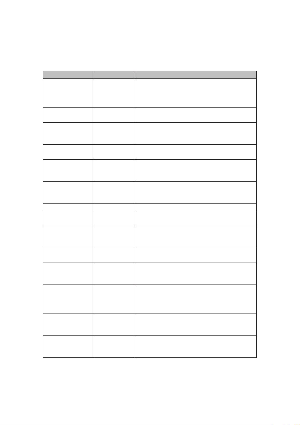
CONTENTS
COPYRIGHT AND LEGAL NOTICES .......................................... 2
INTRODUCTION .......................................................... 6
Key Features ........................................................... 7
About This Manual ...................................................... 7
What’s In The Box ....................................................... 8
Registering your Circuit Mono Station........................................ 9
Power Requirements ..................................................... 9
Glossary ..............................................................10
HARDWARE OVERVIEW....................................................13
Top View – controls ......................................................13
Rear View – connectors ..................................................18
Front and side views .....................................................19
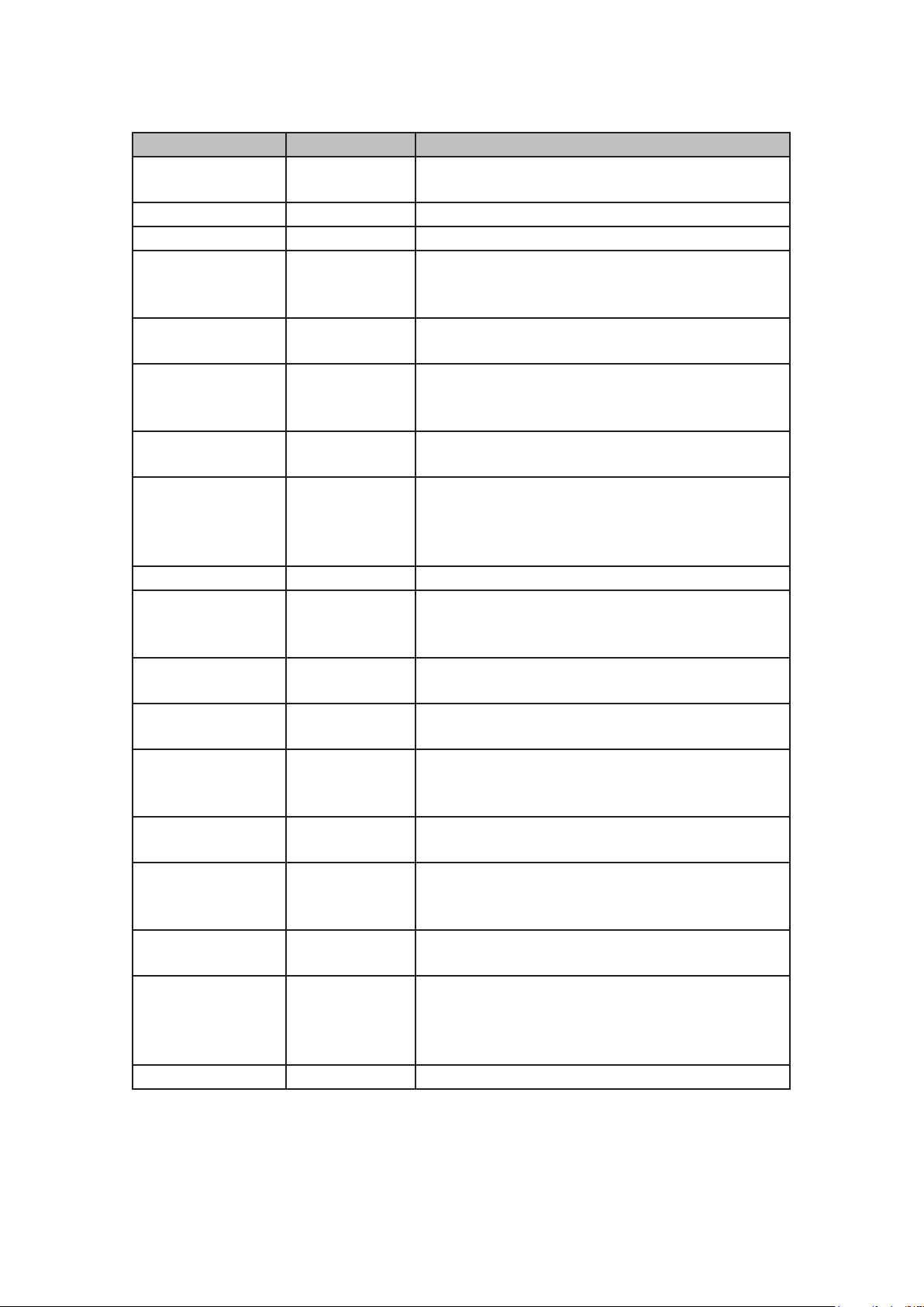
BASICS ................................................................ 20
Powering the unit on .................................................... 20
Getting started..........................................................21
The demo Sessions ..................................................21
Loading and Saving Sessions ......................................... 22
Synth section - basics ................................................... 26
Paraphonic voicing.................................................. 26
Tracks ............................................................ 27
Note View ......................................................... 27
Dual View ......................................................... 28
Expanded Note View ................................................ 29
Scales ............................................................... 30
Scale selection......................................................31
Root note ......................................................... 32
Selecting Patches . . . . . . . . . . . . . . . . . . . . . . . . . . . . . . . . . . . . . . . . . . . . . . . . . . . . . . 33
Patch Preview ..................................................... 34
Initial Patch........................................................ 34
Programming a Pattern .................................................. 35
Step editing ........................................................... 35
Deleting notes ..................................................... 36
Inserting notes ......................................................37
Other note alterations.................................................37
Clear and Duplicate......................................................37
Clearing Steps ......................................................37
Duplicating Steps ................................................... 38
Velocity, Gate and Glide ................................................. 38
Velocity........................................................... 38
Gate . . . . . . . . . . . . . . . . . . . . . . . . . . . . . . . . . . . . . . . . . . . . . . . . . . . . . . . . . . . . . 40
Glide............................................................. 42
3
Page 4

English
The Modulation Sequencer............................................... 44
Smooth ........................................................... 45
Recording a Pattern in real time ........................................... 45
Pattern Settings........................................................ 46
Pattern direction .....................................................47
Pattern length.......................................................47
Pattern Sync Rate .................................................. 48
STORING PATTERNS ..................................................... 50
Patterns View ......................................................... 50
Clearing Patterns........................................................51
Duplicating Patterns .................................................... 52
Pattern Chains......................................................... 52
Pattern Octave ........................................................ 53
Mutate ............................................................... 54
TEMPO AND SWING...................................................... 55
Tempo ............................................................... 55
External clock...................................................... 55
Swing................................................................ 56
Swing sync .........................................................57
Automation of Knobs and Sliders .......................................... 58
SYNTHESIS TUTORIAL.................................................... 59
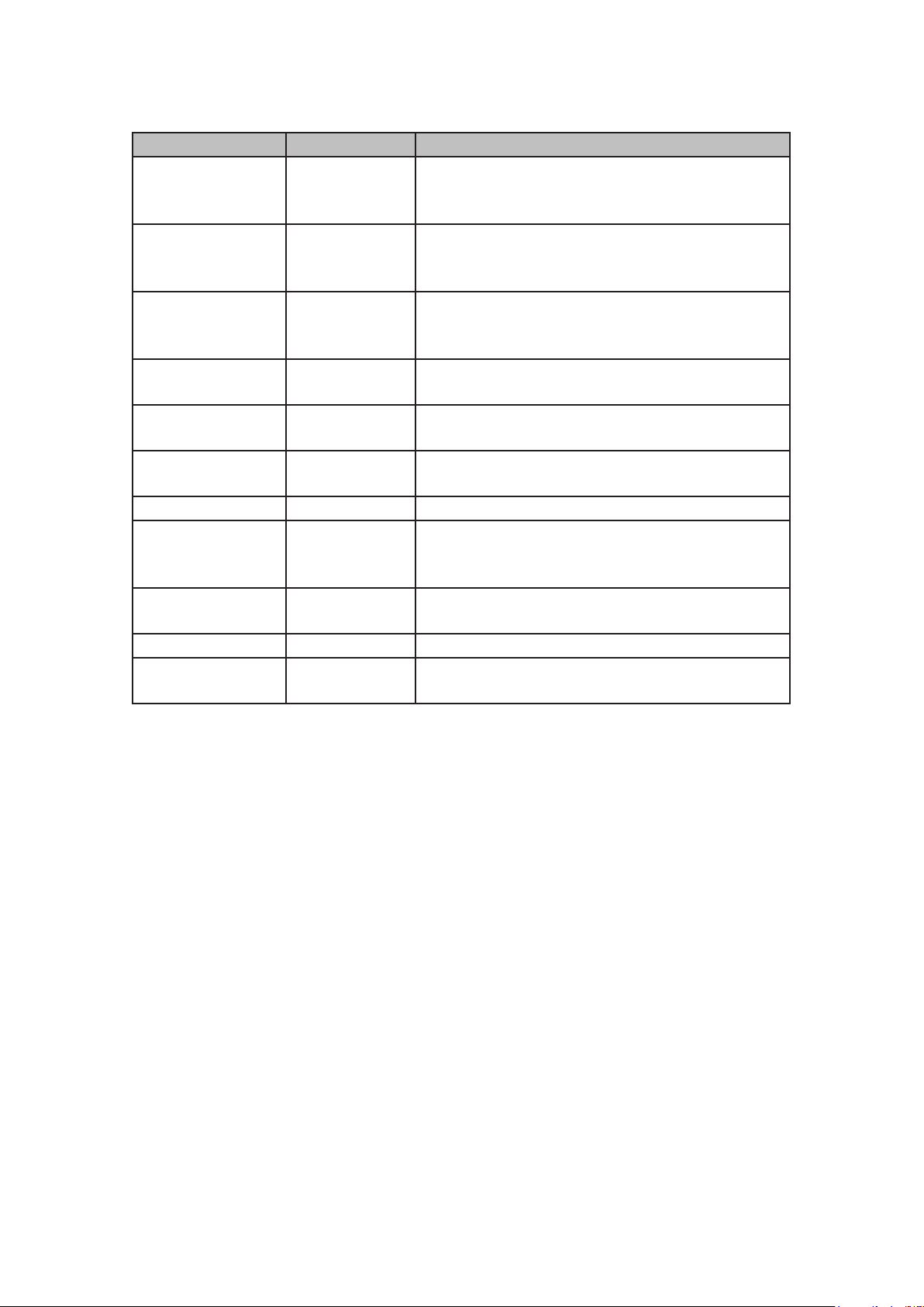
CIRCUIT MONO STATION –
SYNTHESISER SECTION ...................................................71
Sound modication ......................................................71
LED parameter indicators .............................................71
The Filter knob ......................................................71
Pitch and Mod wheels ................................................71
External control .....................................................71
Synthesiser Block Diagram ............................................... 72
The Oscillator section . . . . . . . . . . . . . . . . . . . . . . . . . . . . . . . . . . . . . . . . . . . . . . . . . . . 73
Waveform ......................................................... 73
Pitch ............................................................. 73
Pulse Width ....................................................... 73
Oscillator Sync ......................................................74
The Sub Oscillator ...................................................74
Noise .............................................................74
The Ring Modulator ..................................................74
The Mixer section .......................................................75
External Input.......................................................76
The Filter section........................................................76
Filter Shape ....................................................... 77
Frequency ........................................................ 77
Filter Key Tracking .................................................. 78
Overdrive ......................................................... 79
4
Page 5

English
The Envelope section ................................................... 79
The LFO section ........................................................81
LFO Waveforms .....................................................81
LFO Rate ..........................................................81
LFO Sync ..........................................................81
The Modulation Matrix................................................... 82
Matrix assignment .................................................. 83
The Distortion section ................................................... 85
SYSTEM SETTINGS ...................................................... 86
MIDI I/O .............................................................. 86
MIDI Tx/ R x ........................................................ 86
MIDI Channel .......................................................87
Analogue Clock Rates ................................................87
Pot Pickup ........................................................ 88
SESSION SWITCHING .................................................... 89
Clearing Sessions .................................................. 89
APPENDIX .............................................................. 90
Firmware Updates ...................................................... 90
Bootloader Mode ................................................... 90
Initial Patch Parameters ..................................................91
Session loading problems................................................ 92
5
Page 6

English
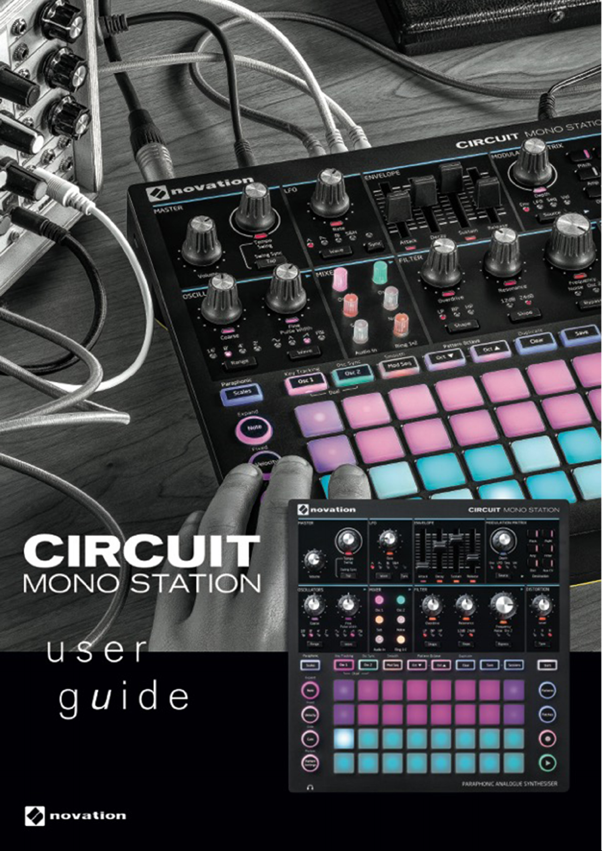
INTRODUCTION
Thank you for purchasing this Novation Circuit Mono Station, the next-generation sequenced
monosynth. Circuit Mono Station is a powerful, but extremely compact electronic musical
instrument combining two established Novation products: the original Circuit groovebox and the
Bass Station II analogue synth. Circuit Mono Station gives you classic analogue synth sounds,
two interacting step sequencers plus a modulation sequencer and full automation of almost all
synth functions.
Circuit Mono Station has been designed to let you create music fast: you can create riffs,
patterns and longer sequences quickly and easily, with the fat and expansive sounds that
only true analogue sound generation can provide. It’s both a compositional tool and a live
performance instrument. You don’t need to connect Circuit Mono Station to a computer or other
device to make music – it’s completely standalone. If you’re working in the studio, Novation’s
superior sound quality means you can use Circuit Mono Station as the basis of your nished
track.
The playing grid is a set of 32 illuminated, velocity-sensitive rubber pads, which act as synth
keys, sequencer steps and have numerous other functions. The pads’ internal illumination is
intelligently RGB colour-coded*, so you can see at a glance what’s going on. You can assemble
patterns together into longer chains, and save your work in one of 32 session memories.
The synth section is reassuringly analogue: the controls - mostly a conventional and familiar
set of single-function rotaries and switches, are always available to tweak your sounds. A large
Filter control is positioned for easy access. There is a host of other quickly-accessible features:
a choice of musical scales, adjustable tempo, swing and velocity, a exible mod matrix and a
unique mixer section featuring internally-illuminated, colour-coded controls.
Circuit Mono Station also sends and receives standard MIDI data, so you can connect other
MIDI-compatible devices, synchronise with other drum machines or grooveboxes, or trigger
synths, for example. The USB connection also handles MIDI; this lets you connect Circuit Mono
Station to your computer so you can synchronise and record MIDI data to your DAW.
A Novation Circuit is the perfect accompaniment to Circuit Mono Station. Using the two units in
tandem gives you a complete solution to electronic music making either in the studio or in live
performance.
For additional information, up to date support articles and a form to contact our Technical
Support Team please visit the Novation Answerbase at:
www.novationmusic.com/answerbase
* RGB LED illumination means that each pad has internal red, blue and green LEDs, each of which can light at
different intensities. By combining the three colours at different brightness levels, almost any colour of illumination can
be achieved.
6
Page 7

English
Key Features
• Combines Bass Station II analogue synth with Circuit step sequencer
• 32-button multi-colour grid for playing and displaying information
• Split grid displays sequence steps and notes simultaneously
• 3-track sequencer: two oscillators plus modulation
• Velocity-sensitive pads
• Paraphonic operation allows the two oscillators to be independently sequenced
• 64 synth Patch memories, pre-loaded with factory sounds
• Tempo range from 40 to 240 BPM, plus tap-tempo mode
• 16 musical scales
• Adjustable Swing
• Patterns can be chained together
• Pattern Settings allow denition of rate, length and direction
• Two analogue oscillators with independent control of parameters
• Sub oscillator, noise generator and ring modulator
• Traditional multi-mode analogue lter section, with pre-lter overdrive control
• Analogue distortion with three modes
• Built-in mixer
• Selectable LFO sync rates including triplets
• 4 x 8 modulation matrix with Mod Depth control
• Clear and Duplicate functions
• Adjustable Note Velocity and Gate (Length)
• Line output (¼” jack)
• Separate headphone output
• USB port for MIDI data and rmware update
• MIDI In, Out and Thru
• CV and Gate outputs
• Assignable auxiliary CV Output
• External Audio Input
• External AC adaptor supplied
• Compatible with Novation Components: back up your sessions and patches on-line
About This Manual
We’ve tried to make this User Guide as helpful as possible for all types of user, both newcomers
to electronic music making and those with more experience, and this inevitably means some
users will want to skip over certain parts of it, while relative novices will want to avoid certain
parts of it until they’re condent they’ve mastered the basics.
Circuit Mono Station combines the technologies of two other Novation products – the Circuit
groovebox and the Bass Station II analogue synthesiser. For clarity, we have tried to keep
the descriptions of the sequencer and synthesiser parts of the unit separate, so after the
Introduction and Getting Started chapters, you’ll next nd a more detailed description of how to
use the sequencer aspects of Circuit Mono Station. As with other Novation synth User Guides,
we’ve then included a “Synthesis Tutorial” (see page 59) which explains the principles of
sound generation and treatment that are the foundation of all synthesisers. We think this will
be of help and interest to all users. Following this, we go into the synth section in full detail. We
hope this arrangement works for you.
There are a few general points that are useful to know about before you continue reading the
User Guide. We’ve adopted some graphical conventions within the text, which we hope all
types of user will nd helpful in navigating through the information to nd what they need to
know quickly:
7
Page 8

English
Abbreviations, conventions, etc.
Where top panel controls or rear panel connectors are referred to, we’ve used a number thus:
6
to cross-reference to the top panel diagram, and thus: 1 to cross-reference to the rear and
side panel diagrams. (See “Top View – controls” on page 13 and “Rear View – connectors”
on page 18).
We’ve used Bold text to name physical things – the top panel controls and rear panel
connectors, and smaller Bold italics to name the various Views that the grid can display.
Tips
These do what it says on the tin: we include bits of advice, relevant to the
topic being discussed that should simplify setting up Circuit Mono Station to
do what you want. It’s not mandatory that you follow them, but generally they
should make life easier.
Extra Info
These are additions to the text that will be of interest to the more advanced user
and can generally be avoided by the novice. They are intended to provide a
clarication or explanation of a particular area of operation.
What’s In The Box
Circuit Mono Station has been carefully packed in the factory and the packaging was designed
to withstand rough handling. Should the unit appear to have been damaged in transit, do not
discard any of the packing material and notify your music dealer.
If practical, save the packing materials for future use in case you ever need to ship the unit
again.
Please check the list below against the contents of the packaging. If any items are missing or
damaged, contact the Novation dealer or distributor where you purchased the unit.
• Novation Circuit Mono Station sequenced monosynth
• USB Type A to Type B cable (1.5 m)
• 3 x MIDI break-out cables: 3.5 mm 3-pole jack plug to 5-pin DIN socket
• Getting Started Guide, including Product/software Registration details
• Safety information sheet
• AC adaptor: 12 V DC, 1.25 A; includes interchangeable AC plug adaptors
8
Page 9

English
Registering your Circuit Mono Station
It is important to register your Circuit Mono Station on-line using the Product/software
Registration details at Step 4 of the Getting Started Guide. Apart from validating your
manufacturer’s warranty, you will also then be able to download the additional software that you
are entitled to as a Circuit Mono Station purchaser:
• Ableton Live Lite music making software
• 1 GB of Loopmasters sounds and samples
The registration details also contain codes you will need to enter in the online forms on our
website to download the software, but before you attempt to do this, warranty registration is
required.
Power Requirements
Circuit Mono Station should be powered from AC mains via the AC adaptor supplied. It cannot
be powered from a computer or other device via a USB connection.
The AC adaptor supplied with the unit is a 12 V DC, 1.25 A type, and can operate on mains
voltages from 100 V to 240 V, 50 or 60 Hz. The adaptor has interchangeable slide-in AC plug
heads; two alternative plug heads are supplied which make the adaptor compatible with AC
outlets in many different countries. Plug heads can be easily swapped if necessary by pressing
the spring-loaded semi-circular button in the centre of the adaptor and sliding the plug head
upwards to separate it from the adaptor body. Then slide in the correct plug head (as shown by
the arrows), ensuring that it locks rmly in place.
The cable from the AC adaptor connects to the coaxial DC input socket on the rear panel of
Circuit Mono Station ( 9 on “Rear View – connectors” on page 18).
The use of AC adaptors of a type other than that supplied is not recommended. Please contact
your Novation dealer for advice on alternative PSUs if necessary.
9
Page 10
English
Glossary
Some of the terms used in this manual have a specic meaning as applied to Circuit Mono
Station. Here is a short list:
Term Button Denition
When the sequencer is running, the “current” note is
Cursor
Dual View Osc 1 + Osc 2
Expand View Shift + Note
Fixed Shift + Velocity
Gate View Gate
Glide View Shift + Gate
Global View A View that allows editing of a whole Session.
Grid pad
Init Session
Key Tracking Shift + Osc 1
Live Record Record
Manual Step Entry
Modulation
Sequence
Mutate Mutate
Mod Seq
indicated by one pad illuminated white: this Step, the
current position in the pattern, is referred to as the
cursor.
Splits the playing grid so that you can access both
Oscillators simultaneously.
Doubles the number of performance pads from 16
to 32, increasing the pitch range from two to four
octaves.
Allows the velocity response of the grid pads to be
disabled.
The Gate value of a note is how many steps it
sounds for. Gate View allows the length of a step to
be edited.
A Glide time may be associated with the notes at
each Step: consecutive notes will glide in pitch
between each other, as dened by the Glide time.
One of the 32 pads making up the main
performance area.
The “empty” Session that will be loaded on power-
up if you hold down Shift + Clear while pressing the
Power button.
A View that allows you to link the Filter frequency to
the pitch of the note.
Lets you add synth notes in real time while a pattern
is playing. Also records any movements of the synth
knobs and sliders.
Assignment of synth notes to specic step in
a pattern. With a step pad pressed, press the
performance pad for the note to be added. Can be
done with the sequencer either running or stopped.
A virtual Track: instead of note data, it carries perstep control parameter data which is available to the
Modulation Matrix as a source.
A single press of Mutate will randomly re-sequence
the Notes making up a Pattern. Per-Note properties
such as Gate and Glide are retained.
10
Page 11
English
Term Button Denition
Note View Note
The View that is used to assign synth notes to
pattern steps.
Paraphonic Mode 1 Shift + Scales Normal mode (default): Only Osc 1 triggers the VCA.
Paraphonic Mode 2 Both Osc 1 and Osc 2 trigger the VCA.
A specic synth “sound”: dened by a set of values
Patch
for all synth parameters. There are 64 Patch
memories, pre-loaded with factory Patches.
Patch View Patches
A Global View which allows synth Patches to be
loaded or saved.
A repeating cycle of synth notes of up to 16 steps,
Pattern
associated with one of the three Tracks. Includes
data for velocity, gate, length and automation.
Pattern Chain
A cyclic set of Patterns played continuously one
after the other.
A View that allows editing of a Pattern. The Pattern's
Pattern Edit View
steps are always visible in these views. Note,
Velocity, Gate, Glide and Pattern Settings View are
all Pattern Edit Views.
Pattern memory Where a Pattern is stored.
Pattern Settings
View
Pattern
Settings
Patterns View Patterns
Performance Pad
A Pattern Edit View that allows the user to edit the
length of a pattern for any Track, set the playback
direction and sync rate.
A Global View which allows Patterns to be loaded or
saved.
The grid pads used to enter synth notes in Note
View or Expand View.
In playback, the white pad which moves through the
Playback Cursor
pattern display, indicating which step is currently
being played. Changes to red in Record Mode.
Playback Mode
Circuit’s operating mode with the sequencer
running; the Play button will be lit bright green.
An operating mode allowing synth notes to be added
Record Mode
to the Pattern. The Record button will be lit bright
red.
Scale View Scales
Allows the user to select one of 16 musical scales.
Also allows transposition of the keyboard.
A set of all necessary data for full playback of
Session
all tracks, including Patches, Patterns, Chains,
automation data, etc. Up to 32 Sessions can be
saved in ash memory.
Sessions View Sessions The View used to save and load Sessions.
11
Page 12
English
Term Button Denition
Allows control of MIDI clock and TX / RX settings.
Setup Page Shift + Power
Normal operation is suspended while the Setup
Page is open.
Applies to the Modulation Sequence: interpolates
between successive assigned values to produce a
gradual transition.
Smooth
Shift + Mod
Seq
By default, each Pattern is subdivided into 16 Steps:
Step
the number of steps may be adjusted in Pattern
Settings View.
Step buttons
Stop Mode
Swing Shift + Tempo
Collective name for the button group comprising the
Note, Velocity, and Gate buttons.
Circuit’s operating mode when the sequencer is not
running.
Adds a subtle variation to the tempo: alternate notes
are shifted in time.
Swing Sync Shift + Tap Sets a range parameter for the Swing control.
The upper section of the top panel: a set of controls
Synth Controls
for the standard sections of an analogue synth, such
as Oscillator, Filter, Envelope, etc.
Tracks
Three Tracks are supported – Oscillator 1, Oscillator
2 and the Modulation Sequence.
Velocity View Velocity Allows editing of the velocity of a step.
View
One of various ways the 32 grid pads can be used to
display information and allow user interaction.
12
Page 13
English
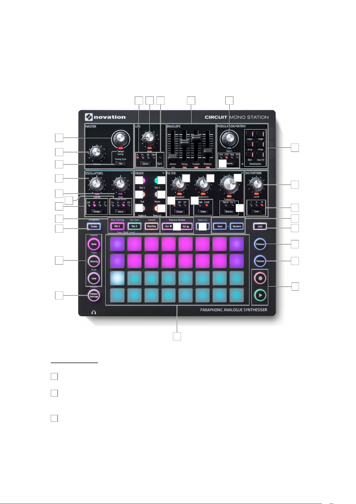
HARDWARE OVERVIEW
Top View – controls
20 29 4021 22
2
1
39
18
19
16
3
23
25
17
27
5
8
6
7
24
26
30 31
28
131212
4
38
3334
32
35
37
36
5
15
9
10
11
Master controls:
1
Volume – controls the overall level at the audio outputs.
2
Tempo – lets you set the BPM (tempo) of the sequence. Hold down Shift to re-assign it as a
Swing control, which will alter the timing between steps to change the ‘feel’ of a pattern.
3
Tap – lets you set the tempo “manually”, by tapping the button. Hold Shift and press Tap to
open Swing Sync View.
13
Page 14

English
Grid controls:
4
32-pad playing grid – a 4 x 8 matrix of rubber pads; internally illuminated with RGB LEDs.
Many Views ‘split’ the grid horizontally into two 2 x 8 matrixes, but some divide it into logical
areas with different functions.
Most of the remaining buttons switch the 32-pad grid into a specic View. Each View provides
information about and control of a particular aspect of the Track, Pattern, timing, etc.
Most buttons have both a momentary (long press) and a latching (short press) mode. A long
press will temporarily display that button’s View, but only while the button is held down. When
released the View will revert to whatever it was before the button was pressed. A short press on
a button will switch the View to that programmed into the button.
Additionally, many of the buttons have a second “Shift” function: in all cases, the name of the
shifted function is silkscreened on the top panel immediately above the button.
5
Track buttons: Osc 1/Osc 2/Mod Seq – three buttons selecting which of the three Tracks
will have their attributes displayed. Osc 1 and Osc 2 may be pressed simultaneously to enter
Dual View, which allows the notes for both oscillators to be played from the same View.
6
STEP buttons: Note, Velocity & Gate – these switch the grid to Note, Velocity and Gate
View respectively, and allow the parameters of each step of the pattern to be individually
entered, deleted or modied.
Pattern Settings
7
: selects a View that allows adjustment of pattern length and sync rate,
play direction and start and end points.
8
Scales – this button allows the selection of one of sixteen different music scales for the
synth keyboard, and also lets you transpose the synth keyboard to a higher or lower key.
9
Patterns – opens a View where you can store multiple Patterns for each Track: sixteen for
Oscillator 1 and eight each for Oscillator 2 and the Modulation Sequence. You can then join
them together to make a Pattern Chain.
10
Patches – this View is where you store your Synth Patches. There are 64 Patch memories,
all of which come pre-loaded with factory sounds. Use the Oct J and Oct K buttons to select
two pages (each of 32 Patches).
11
Play and Record– these two buttons start and stop the sequence (Play) and enter
Record mode (Record). In Play mode anything you play on the grid will be heard; in Record
mode, anything you play will be heard and also added to the sequence.
12
Oct J and Oct K – these let you shift the playing pads’ pitch up by one to ve octaves
or down by one to six octaves. The pitch range of each of the two oscillators is adjustable
independently. Press both buttons together to restore the pads’ pitch to normal (i.e., based on
middle C).
14
Page 15
English
13
Clear – allows deletion of individual Pattern Steps, Patches, Patterns, Sessions or
automation data.
14
Save and Sessions – let you save your current Session, or open a previously-saved one.
You can also use Save to store Patches independently from Sessions.
15
Shift – several of the buttons (and two of the rotary controls) have a “second function”,
which is accessed by holding down the Shift button while pressing the button or knob in
question:
Button/knob Shifted action Shifted function
8 Scales
Note Expand
6
Velocity Fixed
Gate Glide
Pattern
7
Settings
13 Clear Duplicate
Osc 1 Key Tracking
5
Osc 2 Osc Sync Allows Osc 1’s waveform to retrigger Osc 2’s
Mod Seq Smooth
Paraphonic
mode
Switches between Paraphonic Modes 1 and 2
Opens Expand View; doubles the size of the
playing area
Assigns a xed velocity value to each note in a
Pattern
Opens Glide View: allows a glide value to be
assigned to each Step
Mutate Randomizes the Steps in the current Pattern
Operates like a copy-and-paste function for
Patterns or Steps.
Causes the lter frequency to track the pitch of
the note being played
Modies the action of the Modulation Sequence
Track
2 Tempo Swing Time-shifts alternate notes in the Pattern
3 Tap Swing Sync Applies a range parameter to Swing
19 Fine Pulse Width Alters waveform duty cycle for Pulse waveforms
12
Oct J, Oct K
Pattern Octave
Allows the octave of a Pattern to be shifted after
recording
27 Audio In Audio In Gain Adjusts the gain of the external audio input
10 Patches* Init Patch
Pattern (within
Pattern View)
Instant Pattern
Switching
Loads Init Patch: resets all synth parameters to a
default state
A new Pattern will begin playing immediately
instead of waiting for the current Pattern to nish.
* available on software versions 1.1 or later.
15
Page 16

English
Synth controls:
Apart from the MASTER section, the upper half of Circuit Mono Station’s control surface has
the controls for the mono synth engine.
OSCILLATORS section:
Range
16
– steps through the base pitch ranges of the oscillator selected by Osc 1 or
Osc 2 5 in octaves. For standard concert pitch (A3 = 440 Hz), set to 8’.
Waveform
17
– steps through the range of available oscillator waveforms – sine, triangular,
sawtooth and pulse.
Coarse
18
19
Fine – adjusts the oscillator pitch over a range of ±100 cents (±1 semitone).
– adjusts the pitch of the selected oscillator over a range of ±1 octave.
LFO section:
20
Rate – adjusts the frequency of the LFO.
Wave
21
– this button steps through the available LFO waveforms: triangle, sawtooth,
square, sample and hold. The associated LED gives a visual indication of the LFO speed and
waveform.
Sync
22
– press to synchronise the LFO rate to the current tempo clock (internal or external).
35 different sync rate divisions are available: use the Rate control 20 to select one.
MIXER section:
23
Osc 1 – controls level of Oscillator 1’s waveform.
24
Osc 2 – controls level of Oscillator 2’s waveform.
Sub – controls level of the Sub Oscillator signal.
25
Noise – controls the level of white noise added to the sound.
26
Audio In – level control of the signal applied at the rear panel AUDIO IN connector 2.
27
Ring 1*2 – sets the output level of the Ring Modulator circuit: the inputs to the Ring
28
Modulator are Osc 1 and Osc 2.
ENVELOPE section:
A set of four faders adjusting the usual ADSR Envelope parameters (Attack, Decay,
29
Sustain and Release).
16
Page 17

English
FILTER section:
30
Shape – this button steps through three lter characteristics: low-pass (LP), band-pass (BP)
or high-pass (HP).
31
Slope – toggles between two lter slopes: sets the slope of lter outside the passband to
12dB or 24dB per octave.
Frequency – large rotary knob controlling the lter’s cut-off frequency (LP or HP), or its
32
centre frequency (BP).
Resonance – adds resonance (an increased response at the lter frequency) to the lter
33
characteristic.
Overdrive – adds a degree of pre-lter distortion to the mixer output.
34
Bypass – By default, the lter affects all components of the synth’s sound, but its effect on
35
the Osc 2 and Noise signals may be overridden with the Bypass button, which steps through
the two sources both individually and together.
DISTORTION section:
36
Type – distortion is applied after the lter section. This button steps through three distortion
types (I, II and III). Type I produces the distortion used in Bass Station II, Type II is a fuzz type
distortion. Type III is a combination of the two.
37
Level –adjusts the amount of distortion.
MODU L ATI O N M ATRI X:
38
Source – this button steps through the four modulation sources available to the matrix: the
Envelope generator (Env), the LFO (LFO), the Modulation Sequencer (Seq) and velocity (Vel).
39
Destination – six buttons selecting the eight modulation destinations: Pitch and PWM
(Pulse Width Modulation) refer to the two main oscillators, the colour of the internal LED
indicating which oscillator is currently selected by the Track buttons 5. Other destinations are
VCA Level (Amp), Filter frequency (Filter), distortion amount (Dist) and the level of the Aux CV
output (Aux CV).
Depth – adjusts the degree of modulation applied to the selected destination by the
40
selected source. Note that matrix settings are additive: you can apply any combination of
sources to any combination of destinations, with different Depth settings.
17
Page 18
English
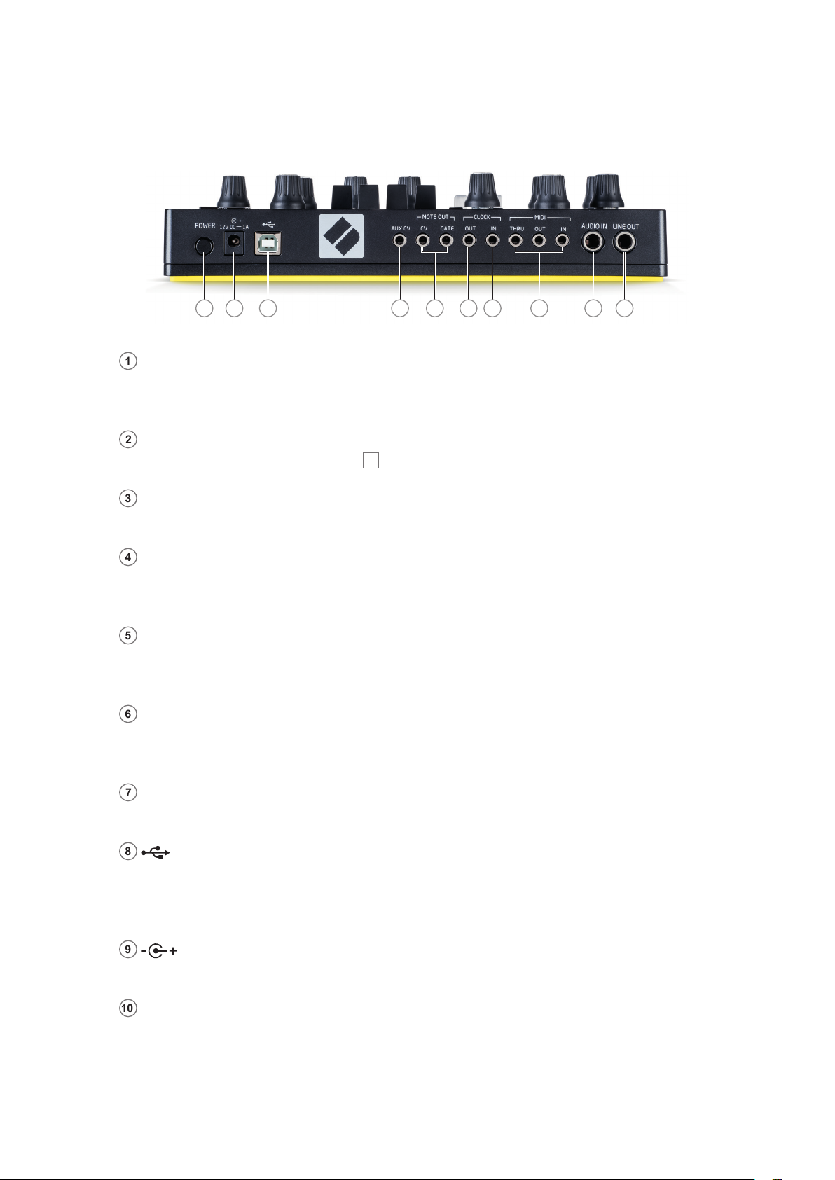
Rear View – connectors
1236 47 58910
1
LINE OUT – the main (mono) audio output on a ¼” TRS jack socket. Max. output level is
+10.5 dBu. The output is pseudo-balanced (ground compensated) and may be connected to
equipment with either balanced or unbalanced inputs.
2
AUDIO IN – a line level input allowing an external audio signal to be added to Circuit Mono
Station’s output (via Mixer level control 27).
3
MIDI IN, OUT and THRU – MIDI connectors on three 3.5 mm TRS jack sockets. Use the
break-out cables supplied to convert these to the industry-standard 5-pin DIN sockets.
4
CLOCK OUT – a 3.5 mm TRS jack socket supplying a clock signal of 5 V amplitude, at a
rate proportional to the tempo clock: the actual ratio can be set in Settings View. The default
rate is one pulse per quarter note.
5
CLOCK IN – a 3.5 mm TRS jack socket for an external clock source. Each pulse applied
advances the sequence by a quarter note. Voltage range: -0.5 V to +5.5 V. Logic ‘low’: <1 V,
Logic ‘High’: >2.3 V.
6
NOTE OUT – two 3.5 mm TRS jack sockets carrying Control Voltage (CV) and GATE
signals derived from Osc 1’s sequence for driving compatible external equipment. The CV
output is scaled at 1 V per octave and the GATE output 5 V amplitude.
7
AUX CV – a secondary CV output (+5 V to -5 V on a 3.5 mm TRS jack socket) whose
source may be assigned in the Modulation Matrix.
8
– Type B USB 2.0 port. A Type B-to-Type A cable is supplied with the unit. The port
is MIDI class compliant; connect to computers and other devices supporting MIDI via USB to
transmit and receive MIDI data. Also used for rmware updates. Note – Circuit Mono Station’s
USB port does not carry either DC power or audio.
9
– power input socket. Circuit Mono Station requires 12 V DC at 1 A. Connect the AC
adaptor supplied to this coaxial socket.
10
POWER – “soft” on/off switch; to prevent inadvertent power up/down, a press of approx. half
a second is needed to turn the unit on or off.
18
Page 19
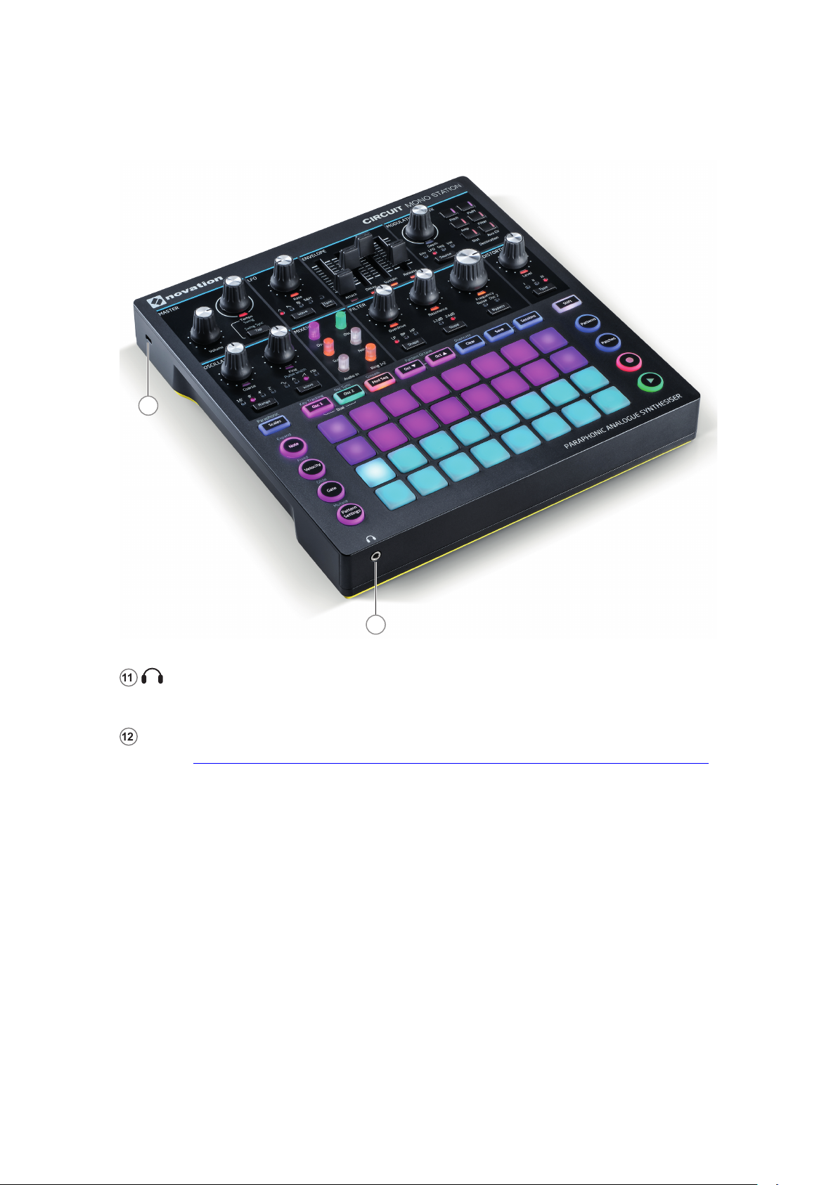
English
Front and side views
12
11
11
(Headphones) – connect a pair of stereo headphones to this 3.5 mm TRS jack socket.
The headphone amplier can drive +10.5 dBu into 150 ohms.
12
Kensington security slot – secure your Circuit Mono Station to a suitable structure if desired.
Please see http://www.kensington.com/kensington/us/us/s/1704/kensington-security-slot.aspx
for further information on how to use this feature.
19
Page 20
English
BASICS
Powering the unit on
Circuit Mono Station must be powered from the supplied AC adaptor. Connect the adaptor to
the DC input socket 10 and plug the adaptor into the AC mains.
Connect the main output to a monitoring system (powered speaker or a separate amplier and
passive monitor) or, if your prefer, plug in a pair of headphones at the front of the unit.
Long-press the Power button 10 to turn Circuit Mono Station on: this will re-load the Session
that was in use last time the unit was on. The rst time you power the unit “out of the box”, this
will be Session 1, which is the rst of the 16 demo Sessions that were loaded at the factory (see
“Getting started” on page 21).
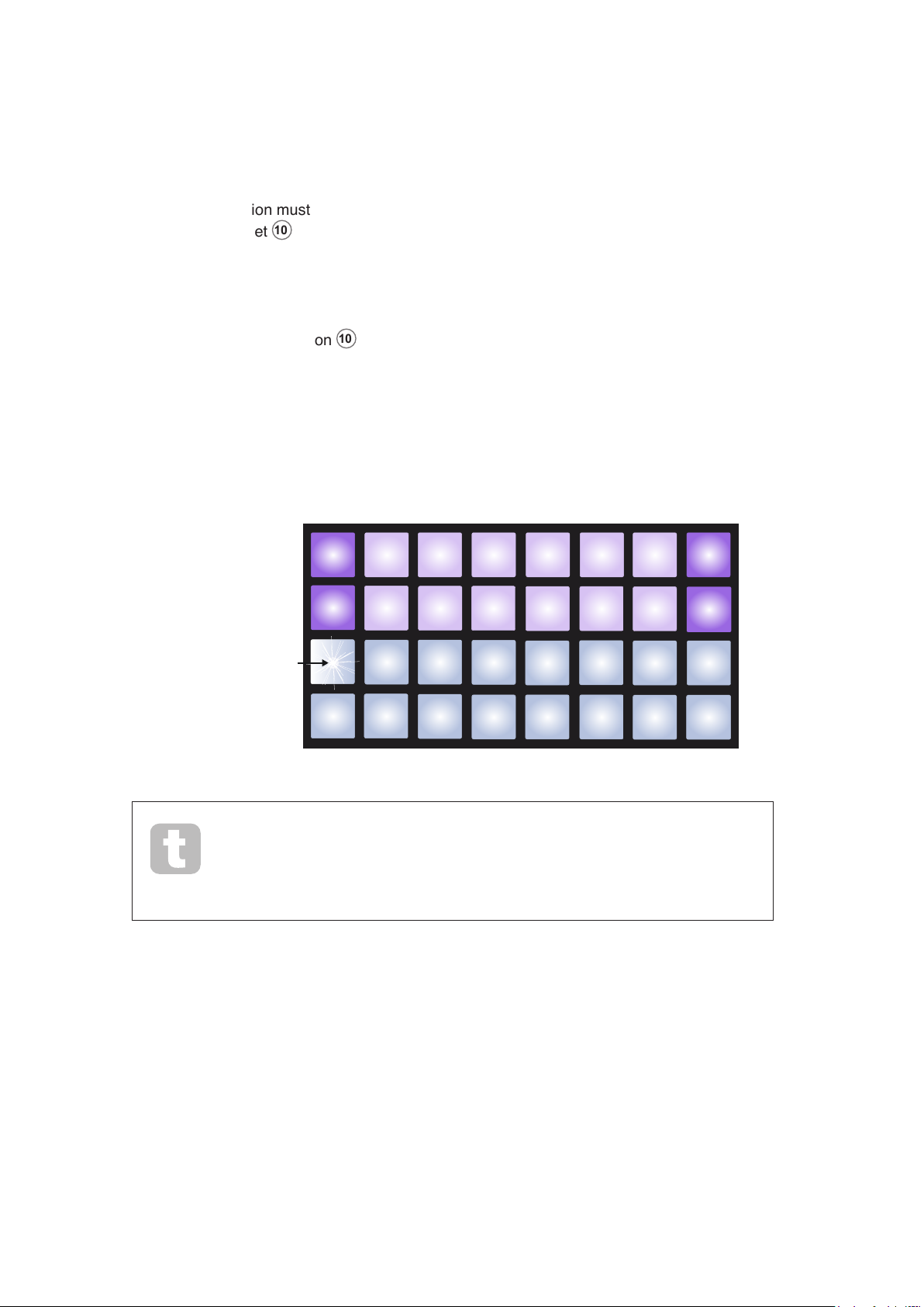
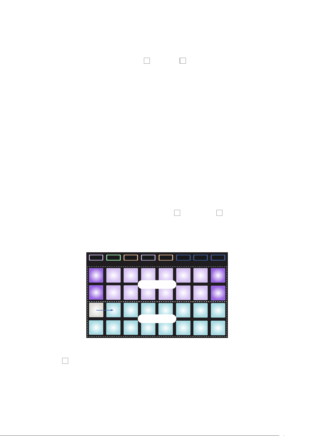
Circuit Mono Station always starts up in Note View, with Osc 1 selected as the displayed Track.
The grid display will look something like this:
Blinking Cyan/White
Pad
You can override the automatic re-loading of the previous Session at power-
up by holding down the Shift and Clear buttons while pressing the Power
button*. This will load the Init Patch instead.
* on software versions 1.1 or later
20
Page 21

English
Getting started
We’ve pre-loaded 16 demo Sessions into the Session memories to give you an idea of how
Circuit Mono Station works. Press the Play button 11; you should hear the rst demo
Session.
If it’s not already lit, press the Osc 1 button 5; Circuit Mono Station is now displaying
Note View for Oscillator 1. The two upper rows – the synth pads - show the notes that Osc 1
is contributing to the sequence, while the two lower rows – the sequencer steps - show the
progression through the Pattern. You can see the contributions made by Osc 2 by pressing
the Osc 2 button. Note that the notes of Osc 1 are coded purple and those of Osc 2 green;
when the Pattern includes a synth note, the pad corresponding to the note changes to white.
Similarly, the sequencer pads are pale blue, but turn white as the “play cursor” moves through
the sequence. Note that the demo Sessions are Pattern Chains – several 16-step Patterns
sequenced together. You can change the tempo with the Tempo control 2.
If you press the Mod Seq button, the Modulation Sequencer View opens, and you will be able to
see how this “virtual” track has been programmed to produce the sonic effects you are hearing.
Press the Play button to stop.
You can listen to other demo Sessions by pressing Sessions 14 and selecting any other pad
on the upper two rows of the grid (each pad in Sessions View represents a Sessions Memory
location).
The demo Sessions
We recommend that you work through the factory demo Sessions, which have been designed
specically to illustrate the various features available in Circuit Mono Station for sound and
Pattern creation. Select different Sessions and spend some time listening to them: we are sure
you will be both impressed by the range of sonic possibilities and curious as to how Circuit
Mono Station was programmed to create them.
First, while playing a Session, select Patterns View (press Patterns 9) to see how multiple
Patterns are chained together for each Track. You can select individual Patterns and listen to
them in isolation, and also turn down the level controls in the Mixer Section to get an idea of
what each Track (and other sources) is contributing to the overall sound. Use the Osc 1, Osc 2
and Mod Seq buttons as described above to see the contributions of individual Tracks.
Note that auditioning just one Pattern of a Pattern Chain effectively cancels the selection of its
“parent” Session, but you can reselect the Session by returning to Sessions View and pressing
its pad again.
By pressing Velocity, Gate 6, Scales 8 or Pattern Settings 7, you can see further Views
which will allow you to see how each of these settings has been programmed or congured
to create what you are hearing. You can also see which Patch was used as the basis for the
Session by pressing Patches 10.
21
Page 22
English
You should also observe the LEDs associated with the various synth controls: with most of the
demo Sessions, you will see these changing in brightness as the Session plays, indicating that
the controls were adjusted in real time as the Patterns were programmed. This is Circuit Mono
Station’s Automation at work - a very powerful feature.
Later in the manual, we explain in detail how each of these Pattern and synth features can be
programmed or congured.
Loading and Saving Sessions
When you power Circuit Mono Station on, the Session played will be the last one used when it
was powered off. The rst time you power it on out of the box, it will play Session 1, which will
contain one of the demos described above.
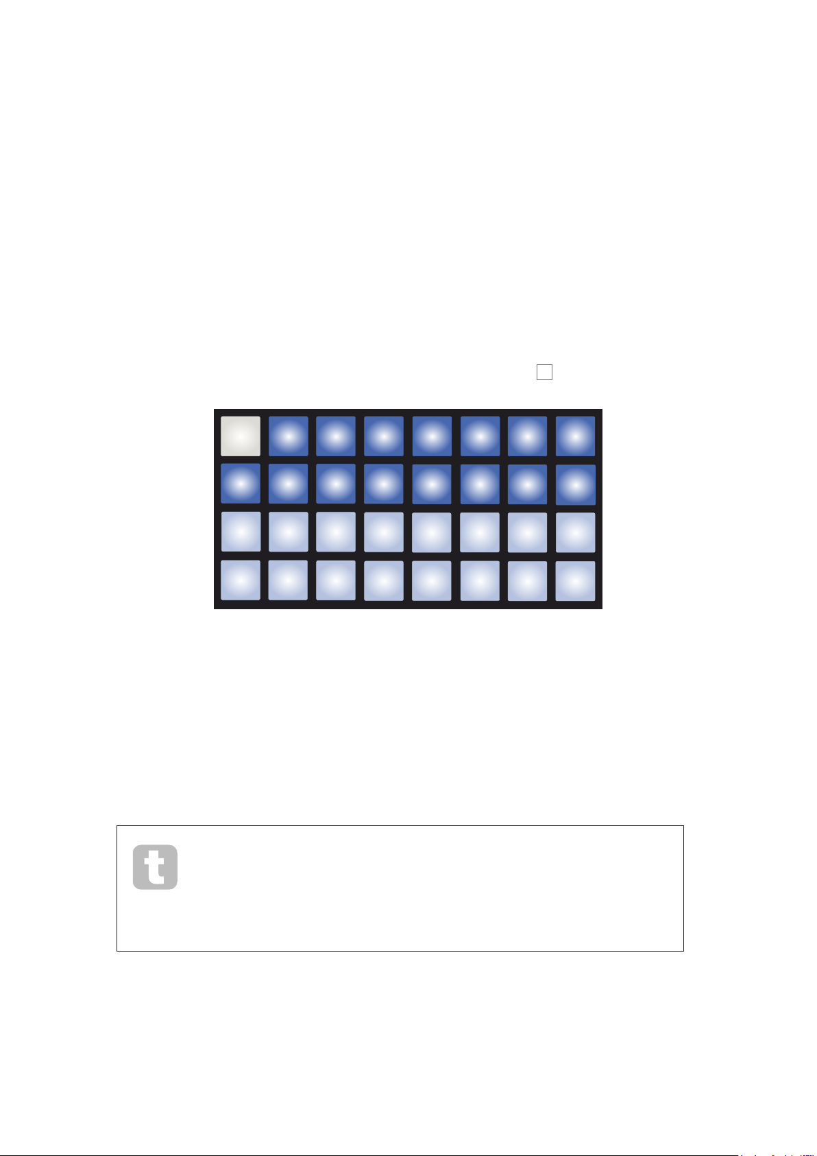
To load a different Session, you use Sessions View. Press Sessions 14 to open this:
Each pad corresponds to one of the memory slots. The pad’s colour indicates the slot’s status:
• Dim blue – slot is empty
• Bright blue – slot contains either a Session saved by the user or a factory demo Session.
(Note that bright blue is the default – you can change the colour to help identify saved
sessions – see the following page.)
• White – the currently selected Session (only one pad will be white)
If you’re still experimenting, you can select a different factory demo to listen to and play around
with. You can jump between saved Sessions while in Play mode.
Sessions loaded when the sequencer is not running will play at the tempo
that was in force when the Session was saved.
Sessions loaded while the sequencer is running will play at the tempo that is
currently set. This means that you can recall different Sessions sequentially
with the condence that the tempo will remain constant.
There’s nothing special about the slots containing factory demo Sessions: you can overwrite
these if you wish.
22
Page 23

English
IMPORTANT – ENABLING SAVE
By now you will probably have read the Getting Starting Guide shipped with your
Circuit Mono Station, so will be aware that Session Saving is disabled, but in case you
haven’t, we’re repeating it here:
The Save function is deliberately disabled before shipping from the factory to prevent
accidental erasure of the demo Sessions. The Save button 14 will initially be unlit,
and before you can save any Sessions of your own, you will need to unlock the Save
function. To do this, hold down the Shift 15 and Save buttons together while powering
Circuit Mono Station on. Save will now be illuminated blue.
You can choose to disable Save in the same way – hold down Shift and Save while
powering Circuit Mono Station on, and the Save button will no longer be illuminated,
indicating that the Save function is now disabled.
Note also that the Clear Session function is also disabled when Save is disabled.
You don’t need to be in Sessions View to save a Session you’ve been working on. If you press
Save 14, the button ashes white; if you press it a second time, it blinks green rapidly for a
second or so to conrm the save process. However, in this case, your work will be saved in the
last selected Session memory, which will most likely be the one that held an earlier version; the
earlier version will be overwritten.
To save your work in a different Session memory (leaving the original version unchanged),
enter Sessions View. Press Save; both Save and the pad for the currently selected Session will
ash white. Press a different memory pad: all the other pads will go dark, and the selected pad
will blink green rapidly for a second or so to conrm the save process.
You can also assign a different colour to any of the pads in Session View – this can be a great
help in live performance. You choose the colour as part of the Save procedure described
above. After pressing Save for the rst time, the Oct J and Oct K buttons 12 will light in the
current colour of the pad for the currently selected Session: if you’ve not already changed the
colour, they will be blue. You can now scroll through a palette of 14 colours by pressing the
Oct J and Oct K buttons. When you see the colour you want, press Save for the second time
to complete the Save process, with green ashes as described above. Note that because you
always save to the currently selected Session memory, and the pad for that is always white,
you won’t immediately see the new colour, but you will do so as soon as you select a different
Session.
23
Page 24
English
Starting from Scratch
Once you’ve experimented with the factory demos for a while, you will probably want to create a
Pattern from scratch.
Select Sessions and select an empty memory slot. Now select Note View and Osc 1. When
you press Play you’ll see the white pad (the play cursor) progressing across the 16 steps of
the Pattern display. Now you can add synth notes. The upper two rows of the grid represent a
music keyboard, the lower two show you where you are in the sequence. When Play is pressed,
you can see the white pad progressing through the steps.
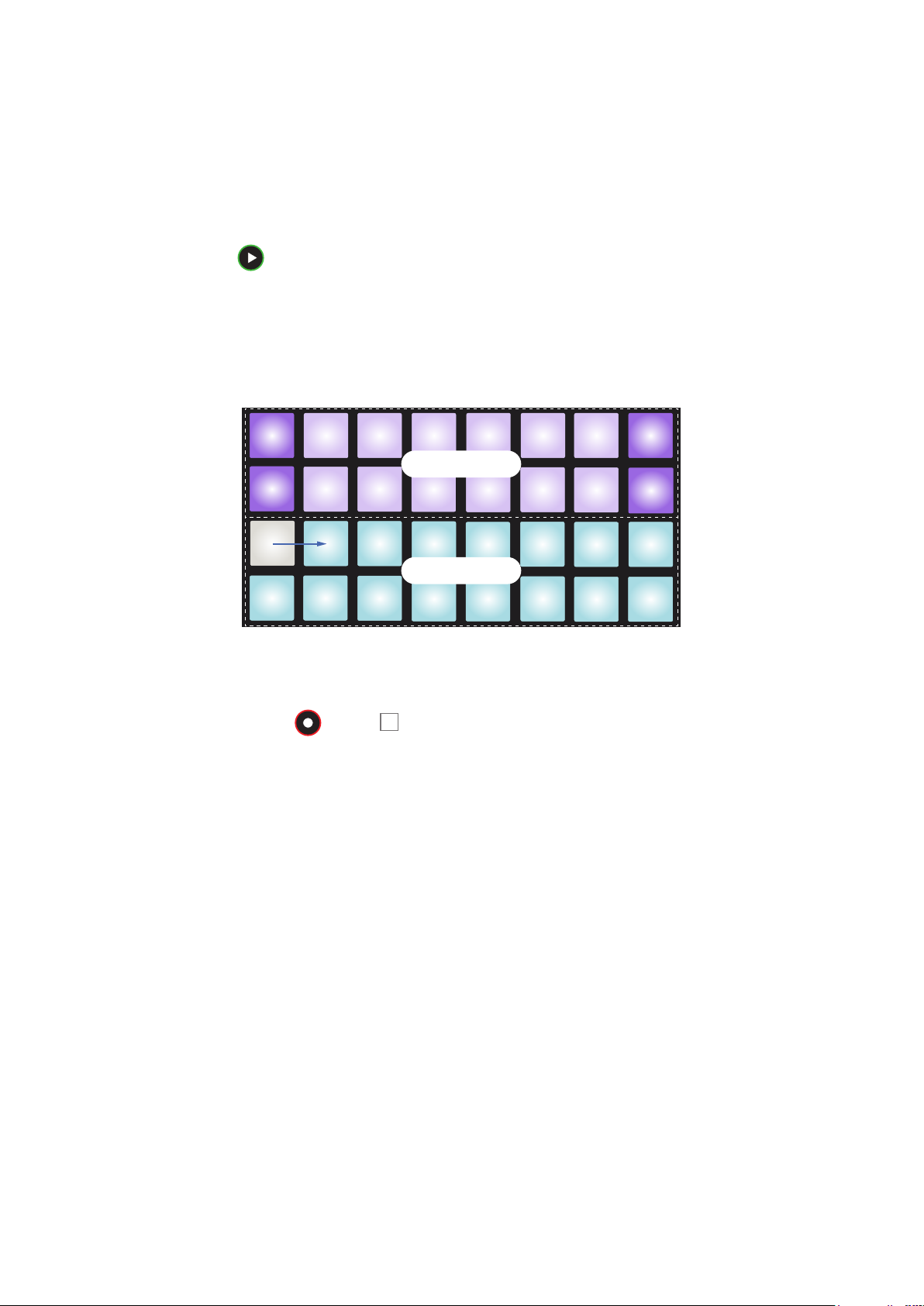
With all scales except Chromatic (see “Scales” on page 30), the grid display looks like this:
Synth keyboard
PLAY
Pattern display
The “keyboard” is two octaves, with the purple pads representing the lowest and highest notes
in each. You can add synth notes in real time by just playing them, or you can add them to
the pattern by pressing Record 11. While the Record button is lit, anything you play will
become part of the pattern.The synth sound you’ll hear when you’ve selected an empty Session
will always be Patch 1.
The Oct K and Oct J buttons alter the pitch range of the currently selected synth keyboard, by
one octave each time they are pressed, up to a maximum of ve octaves above or six octaves
below the default octave. The lowest note in the default octave corresponds to ‘middle C’ on a
standard piano keyboard (providing that different root note for the scale has not been dened –
see “Root note” on page 32).
24
Page 25
English
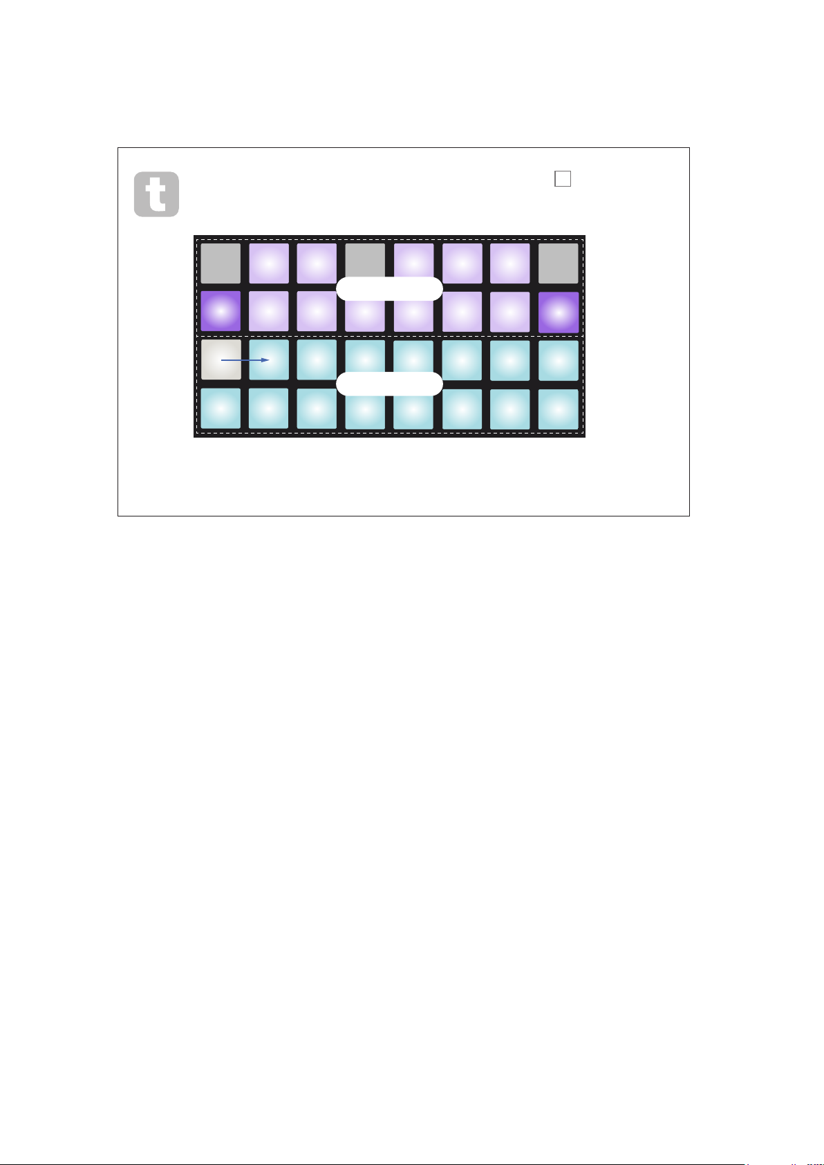
For a conventional piano keyboard, press and hold Scales 8 and then press
Pad 32 (the bottom right one), which will turn red. This gives the keyboard
Chromatic scaling, and the layout differs from that in the other scales:
C# D# F# G# A#
Synth keyboard
C D
PLAY
E F G A B C
Pattern display
Chromatic scaling offers all twelve notes in the octave; to accommodate them, the
keyboard “size” is reduced to one octave.
25
Page 26
English
Synth section - basics
The two synth oscillators – Osc 1 and Osc 2 - have distinctive RGB colour coding for the
pads, which is reected in other Views and in LEDs elsewhere on the control panel, so you
always know which oscillator is being adjusted. Osc 1 uses purple and Osc 2 uses green. On
the playing pads, the high and low C notes in each octave show a different shade than the
intermediate keys.
Paraphonic voicing
A fundamental feature of Circuit Mono Station’s operation is its paraphonic voicing. This means
that the two Oscillators share the synth’s VCA, envelope generator and lter, and can play at
different pitches, but can only be heard together when the envelope is “open”.
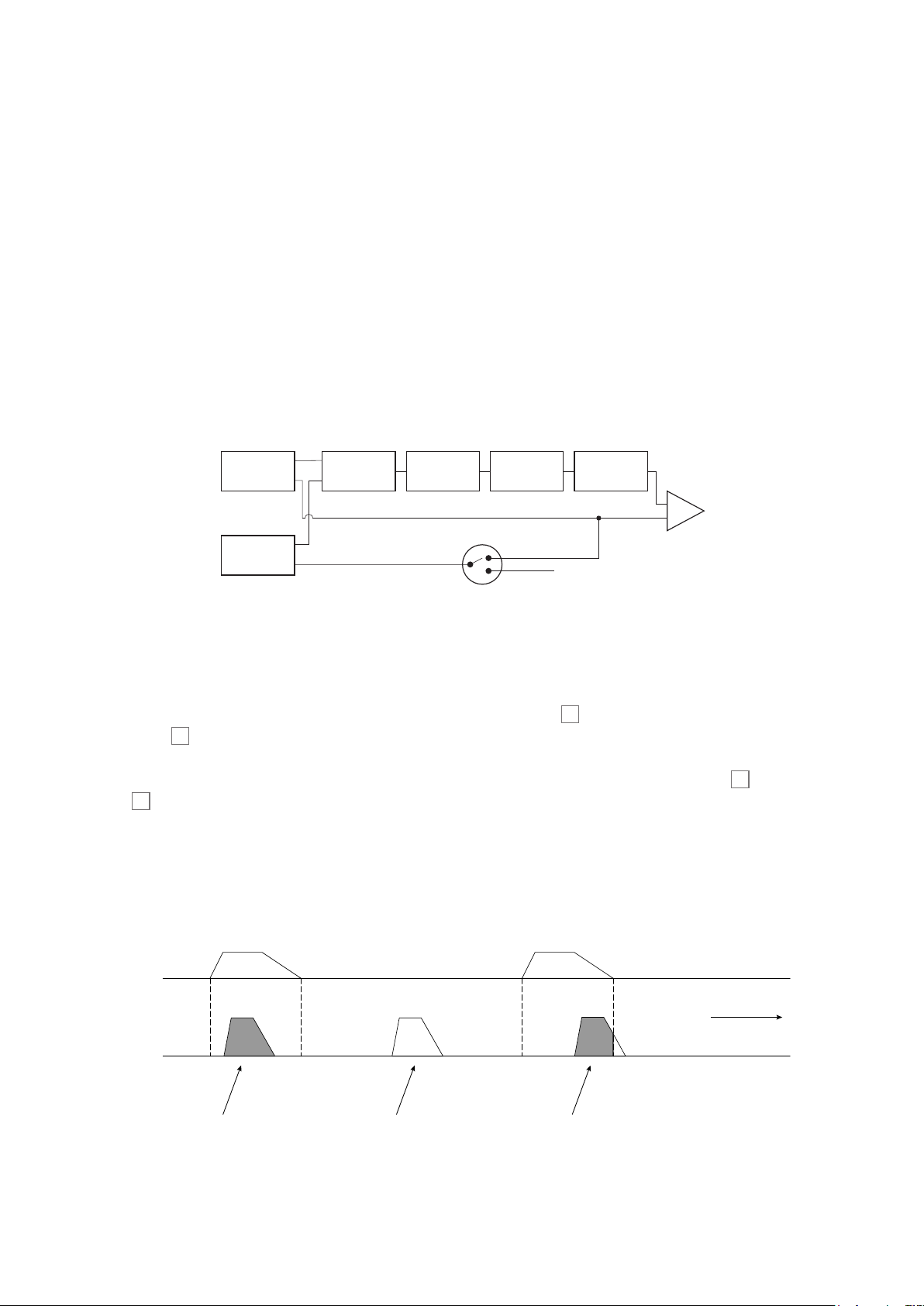
SIMPLIFIED BLOCK DIAGRAM
SHOWING PARAPHONIC MODE SWITCH.
Osc 1
Osc 2
Pitch
Pitch
Trig
Trig
Mixer
Pre-Filter
Distortion
PARAPHONIC MODE SWITCH
VCF
Mode 2
Mode 1
Post-Filter
Distortion
VCA
Trig
In normal (default) operation only Oscillator 1 triggers the VCA. We call this mode Paraphonic
Mode 1, and it is the mode you will use when playing Circuit Mono Station in live performance
or for recording. This mode is conrmed by the Scales button 8 being lit dimly white when
Shift 15 is pressed. In Paraphonic Mode 1, every note played on the keys triggers both
Oscillators, but the VCA is triggered only by Oscillator 1. The contribution that each oscillator
makes to the overall sound can be heard provided the Osc 1 and Osc 2 level controls (23 and
24
) are turned up in the Mixer Section, and the pitch and waveform of each oscillator can be
adjusted independently.
The important point about Paraphonic Mode 1 is that because it is Oscillator 1 that triggers the
VCA, Oscillator 2 will only be heard when a note in Oscillator 1’s Pattern is of sufcient duration
to trigger the VCA. This point is illustrated below:
Osc 1
Osc 2
This note will be heard fully
because Osc 1 has triggered
the VCA
This note will not be heard as the
VCA is not being triggered
PARAPHONIC MODE 1
TIME
Only the start of this note will be
heard because the release phase
of Osc 1’s note will close the envelope
before Osc 2’s note has completed
26
Page 27
English
When creating Patterns, it is obviously helpful to be able to hear each Oscillator’s contribution
while programming. For this reason, Circuit Mono Station has a secondary mode, Paraphonic
Mode 2. This is selected by pressing Shift 15 and Scales 8 together: the Scales button will
now illuminate bright white. In this mode, Oscillator 2 triggers the VCA as well as Oscillator 1, so
you can turn the Osc 1 Mixer level control down and hear all the notes in Oscillator 2’s Pattern.
Tracks
Each of Circuit Mono Station’s two Oscillators constitutes a Track. As described above, the
notes recorded on each Oscillator Track will be interdependent to a degree.
There is also a third “virtual” Track, the Modulation Sequencer. You can use this “data”
Track to record a parameter value for every Step in the Pattern. This can then be selected
in the synth’s Modulation Matrix to control any of the matrix’s controllable parameters, such
as oscillator pitch, pulse width, lter frequency and so on. More details can be found at “The
Modulation Sequencer” on page 44.
Programming the Modulation Sequencer Track (referred to elsewhere in this Guide as
Mod Seq) is a very similar process to programming other per-Step attributes, such as Gate
length, Velocity and Glide. A really powerful feature of Circuit Mono Station though, is that you
can make the Mod Seq data available to other compatible equipment (e.g. Eurorack modules)
with the Aux CV output. These topics are all covered in greater detail further on in this Guide.
Note View
To play a synth in real time, press the Osc 1 Part button 5 and then Note 6. This places the
grid in Note View for Osc 1. Note will illuminate purple. The upper two rows of the grid constitute
the synth keyboard, while the two lower rows show steps the 16-note pattern. Note these are
always illuminated pale blue, apart from the “current” step, which ashes white.
Osc 1 selected
Osc 1
Osc 1
Mod SeqOsc 2
Mod SeqOsc 2
Oct J
Oct J
Oct K
Oct K
Clear
Clear
Save Sessions
Save Sessions
Osc 1 keyboard
PLAY
Pattern display
In order to hear the notes from Oscillator 1, ensure that the Osc 1 level control in the Mixer
section 23 is turned up.
27
Page 28
English
The corresponding Note View for Oscillator 2 can be obtained by pressing the Osc 2 Part
button 5:
Osc 2 selected
Osc 1
Osc 1
PLAY
Mod SeqOsc 2
Mod SeqOsc 2
Oct J
Oct J
Oct K
Oct K
Osc 2 keyboard
Pattern display
Clear
Clear
Save Sessions
Save Sessions
The Osc 2 level control in the Mixer section 24 must be turned up and Paraphonic mode 2
selected (by pressing Shift + Scales) in order for Oscillator 2’s notes to be audible. Note that
the Scales button is illuminated bright white when Mode 2 is active.
With the exception of the Chromatic scale (see Scales, page 30), the top row of playing pads
contains notes one octave above those in the second row. The highest note of the lower octave
(Pad 16) is the always the same as the lowest note of the upper octave (Pad 1). Thus to play
the notes over two octaves in ascending order, start with Pads 9 to 16, then 1 to 8.
When Circuit Mono Station is powered up and an empty or new Session selected, Middle C
will normally be the lowest note of the two octave keyboard (Pad 9). It is possible to alter the
keyboard ‘layout’ so that the bottom note is something other than C – see page 30. The
oscillators have a total range of 12 octaves; you can access higher or lower pairs of octaves by
using the Oct J and Oct K buttons 12. Note that at the highest and lowest octave settings,
the ‘size’ of the keyboard is limited.
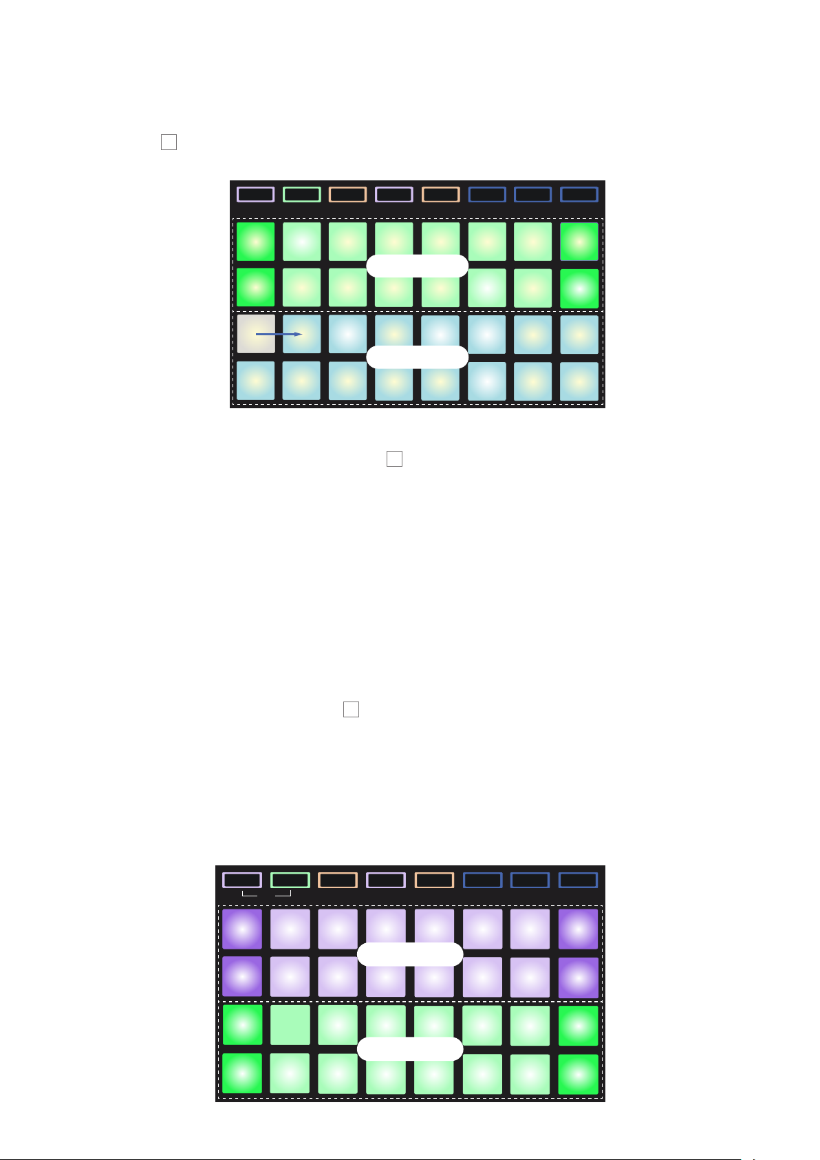
Dual View
If you press both Osc 1 and Osc 2 together, Circuit Mono Station enters Dual View. This lets
you access a two-octave keyboard for both Oscillators simultaneously, which is great for
getting to grips with the unit’s paraphonic potential in real time.
Osc 1
Osc 1
Dual
Mod SeqOsc 2
Mod SeqOsc 2
Osc 1 keyboard
Osc 2 keyboard
Pressing Note returns the grid to Note View.
Oct J
Oct J
Oct K
Oct K
Clear
Clear
Save Sessions
Save Sessions
28
Page 29

English
Expanded Note View
To obtain a keyboard with a wider range, hold down Shift 15 and press Note 6; Note now
illuminates white. This View is Expanded Note View, and removes the pattern display in the
two lower rows of the grid, replacing it with keys for the next two lower octaves of the selected
scale.
Osc 1 selected
Osc 1
Osc 1
Mod SeqOsc 2
Mod SeqOsc 2
Oct J
Oct J
Oct K
Oct K
Osc 1 keyboard
Clear
Clear
Save Sessions
Save Sessions
Osc 2 selected
Osc 1
Osc 1
Mod SeqOsc 2
Mod SeqOsc 2
Oct J
Oct J
Oct K
Oct K
Clear
Clear
Save Sessions
Save Sessions
Osc 2 keyboard
This View is very useful when recording synth notes in real time.
Expanded Note View can be cancelled by pressing Note again; the lower two rows of the grid
now resume the pattern’s step display.
29
Page 30

English
Scales
Circuit Mono Station is extremely exible in how it lets you congure the note pads in the
playing grid to suit many musical genres in key or scale. There are two aspects to specifying
how the note pads are laid out: the scale and the root note.
Up to 16 musical scales are available: these include those common in western musical styles
such as major, natural minor, pentatonic and chromatic as well as more unusual scales (or
modes) such as Dorian, Lydian and Mixolydian. Not all these scales contain eight notes, though
the only one that has more than eight is Chromatic, with 12.
You don’t need to understand musical theory to make use of different scales.
Because Circuit Mono Station lets you alter the scale in use after you’ve
created a pattern, it’s easy to get an idea of their effect and their differences.
Record a simple pattern of synth notes, and then play it back using different scales.
You’ll notice that with some scales certain notes shift up or down a semitone, and that
this gives the “melody” you’ve composed quite distinct “moods” or “feels”, some of
which will be more suited to what you’re trying to achieve than others.
Furthermore, although the default keyboard is based on a note of C (as described in the
previous section), it is possible to redene the lowest sounding note to be any note of the
chosen scale.
Both scale and root note are set using the Scales View, accessed by pressing the Scales
button 8. The Scales View will look similar to that shown below:
Currently-selected
starting note
Currently-selected
scale
C#
1 2 3 4 5 6 7 8
C D
9 10 11 12 13 14 15 16
17 18 19 20 21 22 23 24
25 26 27 28 29 30 31 32
Eb F# Ab Bb
Keynote Selection
E F G A B
Scale Selection
30
Page 31

English
Scale selection
In Scales View, the bottom two rows allow selection of one of the 16 available musical scales.
These are listed in the table below, with the notes that each scale includes when the lowest
note in the scale is C:
Pad Scale C C# D Eb E F F# G Ab A Bb B
17 Natural Minor
18 Major
19 Dorian
20 Phrygian
21 Mixolydian
22 Melodic Minor (ascending)
23 Harmonic Minor
24 Bebop Dorian
25 Blues
26 Minor Pentatonic
27 Hungarian Minor
28 Ukranian Dorian
29 Marva
30 Tod i
31 Whole Tone
32 Chromatic
✓ ✓ ✓ ✓ ✓ ✓ ✓
✓ ✓ ✓ ✓ ✓ ✓ ✓
✓ ✓ ✓ ✓ ✓ ✓ ✓
✓ ✓ ✓ ✓ ✓ ✓ ✓
✓ ✓ ✓ ✓ ✓ ✓ ✓
✓ ✓ ✓ ✓ ✓ ✓ ✓
✓ ✓ ✓ ✓ ✓ ✓ ✓
✓ ✓ ✓ ✓ ✓ ✓ ✓
✓ ✓ ✓ ✓ ✓ ✓
✓ ✓ ✓ ✓ ✓ ✓
✓ ✓ ✓ ✓ ✓ ✓ ✓
✓ ✓ ✓ ✓ ✓ ✓ ✓
✓ ✓ ✓ ✓ ✓ ✓ ✓
✓ ✓ ✓ ✓ ✓ ✓ ✓
✓ ✓ ✓ ✓ ✓ ✓
✓ ✓ ✓ ✓ ✓ ✓ ✓ ✓ ✓ ✓ ✓ ✓
The scale you choose to play in will be saved when you save the pattern.
You will see that when you select a different scale in Scales View, the illumination of the pads
in the upper two rows changes. If you are familiar with a piano keyboard, you will see that the
arrangement of pads simulates the layout of keys over one octave (initially starting at C), with
Row 2 representing the white notes and Row 1 the black notes. Note that Pads 1, 4, 8 and 16
are always disabled in this view, to allow pads 2 and 3, and 5, 6 and 7 to act as the black notes.
The brightly lit pads are those that belong to the selected scale, the dim ones are the notes that
don’t belong.
31
Page 32

English
When you exit Scales View by pressing Note again, the upper two rows in Note View now
contain the notes in the selected scale, over two octaves. There is one exception to this –
Chromatic scale. With this scale selected all 12 notes in the scale are available, which means
that only a one-octave keyboard is possible to accommodate them. The upper two rows in
Note View now have the same layout as in Scales View. In Expanded Note View, a two-octave
keyboard is presented with Chromatic scale selected.
C# Eb F# Ab Bb
Upper octave (Cn to C
C
n
C
n-1
D
C# Eb F# Ab Bb
D
E F G A B
Lower octave (C
E F G A B
n-1
n+1
to Cn)
)
C
n+1
C
n
Chromatic Scale in Extended Note View
Root note
The default root note for all scales is C. In the Scales View shown at page 30, Pad 9,
corresponding to C, is lit a darker blue than the other pads. To change the keyboard root note
in Note View, select a different note in Scale View. (Note that the top two rows of Scales View
always show an octave from C to B.) When a different root note is selected, the pad illumination
changes to indicate the notes available in the currently selected scale for the new key.
For example, if you are working in the Major scale, and select G as the root note, the Scales
View will look this:
G selected as
root note
Major scale
selected
C#
1 2 3 4 5 6 7 8
C D
9 10 11 12 13 14 15 16
17 18 19 20 21 22 23 24
25 26 27 28 29 30 31 32
D# F# G# A#
Keynote Selection
E F G A B
Scale Selection
The upper two rows now show the notes making up the G major scale: G, A, B, C, D, E, and F#.
32
Page 33

English
In Note View, each of the two upper rows (or each of all four rows in Expanded Note View) will
now sound the notes of the G major scale, running from G to G’ (where G’ denotes a note one
octave above G). The same principle can be applied to re-scale the synth note pads in the Note
Views to any desired root key.
If you have already created a pattern including synth notes, you can change the keynote to
transpose the pattern, even while the pattern is playing. You can also change the scale itself for
an existing pattern. In this case, some notes in the pattern as it was created may not exist in the
new scale. In such a case, Circuit Mono Station makes an intelligent decision as to which note
to play instead, which will normally be either one semitone above or below the original note.
Selecting Patches
Circuit Mono Station has 64 memory locations for synth Patches, which dene the synth’s
sound by assigning predetermined values to the various controls. All 64 memory locations are
pre-loaded with factory Patches developed specically for Circuit Mono Station. To load a Patch
press the Patches button 10. This opens the Patch View Page 1.
Osc 1
Osc 1
Mod SeqOsc 2
Mod SeqOsc 2
Oct J
Oct J
Oct K
Oct K
Clear
Clear
Save Sessions
Save Sessions
The two pages are selected with the Oct J and Oct K buttons 12. In Page 1, Oct J is
illuminated bright white and Oct K dim white. Pressing Oct K will open Patch View Page 2.
Each of the pads in the grid represents 32 of the 64 factory Patches: Patches 1 to 32 are on
Patch View Page 1 and 33 to 64 are on Patch View Page 2. To view the other page in the case of
either synth, press the non-illuminated Octave button.
The pad corresponding to the currently selected Patch will be illuminated white and the others
will be deep blue. To select a different Patch, press its pad: it will illuminate white and the
previously pad will turn blue. The synth will now adopt the sound dened by the new Patch.
You can change Patch while a Pattern is running, though the transition may not be absolutely
smooth, depending on the point in the Pattern when the pad is pressed. Changing the Patch of
a saved Pattern does not alter the Patch that was originally saved with the Pattern, unless the
Session is re-saved.
Note that if you changing the Patch while listening to a demo Session (for example) may
not sound quite like what you expected, as the Patch used for the Session will have had its
parameters tweaked during Session creation.
33
Page 34

English
The currently-selected Patch will be applicable to the whole of the current Session: you can’t
use different Patches for different Patterns in the same Session. However, Circuit Mono
Station’s extensive range of synth parameters should render this irrelevant in most cases.
Once you’ve made changes to one of the factory Patches, or created a new one from the initial
Patch, you can save the result in one of the memory locations. In doing this, you will need to
overwrite one of the factory Patches, so choose one you’re not likely to need. In any event, the
factory Patches can be easily reinstated using Novation Components. Full details about saving
Patches and using Novation Components can be found later in this Guide.
Patch Preview
Patch Preview is a feature available in rmware version v1.1 onwards.
Patch Preview lets you audition a Patch while in Patch View, making Patch selection very
simple. You don’t have to do anything: you will automatically hear the Patch as you select it.
If you don’t want the Patch to sound, hold down Shift 15 while pressing the grid pad: this will
simply select the Patch as normal.
Initial Patch
You may sometimes want a very basic sound to work with. To meet this need, we’ve provided
an Initial Patch (referred to elsewhere as “Init Patch”), which you can load quickly any time:
you can tweak and add to until it’s what you’re after. To load Init Patch, open Patch View, hold
Clear 13 down and press any grid pad. This will temporarily overwrite Init Patch into that Patch
memory, but the factory Patch will still be there next time you power-up. You can also* load Init
Patch by pressing Shift 15 and Patches 10 together.
Init Patch isn’t very interesting; it’s intended as a “starting point” from which a more complex
sound can be created. See “Initial Patch Parameters” on page 91 for a list of synth
parameters for Init Patch. The initial sound for both Oscillators is a sawtooth waveform in the
8’ pitch range with a medium release time. Init Patch is actually a good Patch to use to explore
how the synth controls work, simply because it is so basic. The controls in the synth section
are discussed in full detail elsewhere in the User Guide, but you can get an idea of the effect of
each for now by tweaking and listening!
* on rmware versions 1.1 or later.
34
Page 35

English
Programming a Pattern
To program a synth Pattern in Paraphonic Mode 1 (the default), rst select a Patch as described
in “Selecting Patches” on page 33. Enter Note View for Oscillator 1 (press Note and then Osc
1 if not already selected).
To assign a note to a Pattern step, press and hold the pad for the step – it will turn red – and
simultaneously press the pad for the note to be assigned, which will also turn red while it is
being pressed. For example, if you want your Pattern to start with the scale root note (which will
be C unless you’ve changed it) on beat 1 of the Pattern, press and hold Pad 17 (the rst step
in the Pattern) and then press Pad 9. When you run the sequence, the note of C will now play
on step 1 of the 16-step Pattern. You can add further notes to other steps in exactly the same
way. Note that once notes have been assigned to steps, the pads for those steps will illuminate
bright blue.
Note that the two Octave buttons 13 have no effect on the pitch of the notes once they’ve been
recorded; you need to decide which octave you’re going to play in at the time of recording.
However, you can still alter the octave of the pattern after recording by holding down Shift
when pressing Octave.
The two parameters in Scales View – Scale and Root Note – can both be altered during
playback as well, so if you like the pattern, but it’s in the wrong key to t with another musical
element, you can just press Scales and select a different root note.
Using Paraphonic Mode 2 (see “Paraphonic voicing” on page 26), exactly the same
procedure can be used to program Steps for Oscillator 2.
Step editing
Step editing operations in Circuit Mono Station may either be done with the pattern running (i.e.,
in Play mode), or not running (i.e., in Stop mode).
Circuit Mono Station gives you the means of adding or deleting individual notes in a pattern
without needing to worry about accurate timing, as editing is step-based and doesn’t require
the notes to be accurately entered.
All the following details apply equally – and independently - to Osc 1 and Osc 2. Press the
Osc 1 or Osc 2 buttons to see the individual contributions of the two Tracks to the overall
pattern. Bear in mind the need to select Paraphonic Mode 2 – by pressing Shift + Scales - to
hear the Pattern assigned to Oscillator 2.
In Note View (but not Expanded Note View), the two lower rows of grid pads represent the 16step pattern and the two upper rows are the performance pads. When a pattern is played, you
can see the white pad moving through the 16 steps. When a step has a note associated with it,
the performance pad in the two upper rows corresponding to the note being played illuminates
white while the note is sounding (but see the following page regarding octaves).
When the pattern is not playing, you can listen to the notes assigned to each step and alter the
pattern manually. When the pattern is playing, you will only hear the notes associated with each
step when the sequence gets to the step.
35
Page 36

English
The pads for the steps which have notes associated with them will be illuminated bright blue.
One step pad will ash white/blue: this shows where the pattern had reached when it was
stopped. This is shown in the rst diagram below. However, when you press Play again, the
pattern will always restart from Step 1.
Performance pad
illuminates red to
indicate note
at step
Press and hold step
pad down to see
which note is
assigned to it
Bright blue steps
have notes
assigned to them
(HOLD)
Blinking cyan/white
pad is the cursor:
the current position
in the sequence
If a bright blue step pad (i.e., one corresponding to a synth note) is pressed and held, it
illuminates red, the note at that step will sound, and the performance pad corresponding to the
note will also illuminate red. The pad stays red and the note sounds for as long as the step pad
is held down.
The above description holds good as long as the currently selected octave is the same as
that used to record the note. (Remember that although you can’t change the octave of a note
once it’s been recorded, you can shift the octave of the performance pads up or down when a
pattern isn’t playing.) If you press a brightly-lit step pad but no performance pad illuminates red,
it means that the note you are hearing – the one recorded for that step – lies in another octave.
Use the Oct J or Oct K buttons 12 to move to another octave to nd where the note is: a
performance pad (or pads) will light red when you hit the right octave. You can hold the step
pad down while pressing the Octave buttons to do this. With a bit of listening practice, you’ll be
able to guess the octave a note lies in relative to the one the performance pads are currently
set to.
Deleting notes
If a note is incorrect, you can easily delete it by pressing the step pad for the unwanted note
(both the step pad and the assigned performance pad will then light red) and then press the
performance pad. The note is deleted and performance pad will resume the colour of the other
(unplayed) notes according to the oscillator being displayed – purple or green.
36
Page 37

English
Inserting notes
You can add synth notes to a pattern by selecting the step where the note is to go by holding
down the pattern pad for that step, pressing the required performance pad, and then releasing
the pattern pad. You don’t have to press Record. Now when you run the pattern, you will nd
that the note has been added.
You can also insert notes by reversing this sequence: you can select the note rst by pressing
and holding a performance pad and then pressing a Step pad to assign the note to that Step.
Remember that you can add notes in any octave, but the octave you select will determine the
octave displayed on the performance pads, so if all your existing notes are in the mid-range
and you want to add a bass note, the performance pads will not display any of the higher notes
once you’ve selected a lower octave.
Other note alterations
If you want to change the note at a Step to a different note, simply assign the new note as
described above, which will automatically cancel the previous one, as only one note may
be assigned to each Step. The procedure needs to be done this way to retain the Gate and
Velocity values for the original note. If you delete the original note and then enter the revised
note, you will nd that the new note has the default values for Gate and Velocity.
You can also alter the duration (Gate) and Velocity value of individual notes. These topics are
covered in a subsequent section of the Guide.
Clear and Duplicate
Circuit Mono Station’s Clear and Duplicate (Shift + Clear) functions can be applied to Patches,
Patterns and Sessions as well as the individual steps in a Pattern. Here we are concerned only
with Clearing and Duplicating steps.
Clearing Steps
You can also delete assigned synth notes from a step using the Clear button 13. This has
the advantage that you don’t have to search through the octaves to nd a note that isn’t in the
currently-displayed octave.
Press and hold Clear; the button will illuminate bright red to conrm Clear Mode. Now press the
step pad; it will turn red and the note for the selected oscillator at this step will be deleted. The
step pad will revert to its dim “unassigned” illumination when this has been done. Release the
Clear button to exit Clear Mode; its illumination will return to dim blue to conrm that the clear
procedure is complete.
The Clear button has an additional function in Patches View, Patterns View and Sessions View;
see “Initial Patch” on page 34, “Clearing Patterns” on page 51 and “Clearing Sessions” on
page 89.
37
Page 38

English
Duplicating Steps
Pressing Shift + Clear 15 and 13 enables the Duplicate function, which performs actions very
similar to “copy-and-paste” for Steps.
In Note View for any of the Tracks – including Mod Seq - you can use Duplicate to copy the
note at a step, complete with its various attributes, to a different step in the Pattern.
Duplicate is the shifted function of the Clear button 13: to copy step data from one step to
another, press and hold Shift and Clear together: the Clear button will illuminate bright green.
Press the pad in the two lower rows corresponding to the step to be copied (the ‘source’ step);
it will illuminate green. Now press the pad corresponding to the step where the data is to be
copied to (the ‘destination’ step); this will give a single red blink. All the note information in the
source step will now have been duplicated in the destination. Any pre-existing note information
in the destination step will be overwritten. Upon release, the Clear button will return to dim
blue to indicate that the duplication procedure is complete. If you want to copy the note data to
several steps, you can continue to hold the Shift and Clear buttons down, and simply repeat
the “paste” part of the operation to the other steps.
Velocity, Gate and Glide
Every step in a pattern has three further parameters that are available to you to adjust. These
are Velocity, which determines how the volume of a note is related to how hard the pad is
struck, Gate, which sets the duration of the note, and Glide, which adds a portamento effect to
a note.
Velocity
The velocity parameter measures how hard the pad is hit during Live Record, and can be
subsequently edited. What the Velocity parameter then controls will be determined by what it is
routed to in the Modulation Matrix. If it is used to control the VCA (by selecting Vel as the Matrix
source and Amp as the Matrix destination), it will be directly related to volume, and can be
scaled – as can any other Modulation Matrix routing – with the Depth control 40.
See page 82 for full details of how to use the Modulation Matrix.
In Live Record, Velocity values are assigned to each step as you play the performance pads.
Note that Velocity values are associated with the Pattern step, not with the note.
Circuit Mono Station lets you change the Velocity value of a step to any of 16 values, after
you’ve created a Pattern. This is done in Velocity View, which is selected by pressing Velocity
6
, which illuminates in the colour of the currently selected Oscillator.
This indicates a
Velocity value of 11
The three dark blue
steps have
synth notes
associated with them
One step pad blinks
blue/white; this is
the step whose
Velocity value is
displayed
1 2 3 4 5 6 7 8
9 10 11 12 13 14 15 16
Velocity value display
Pattern step display
38
Page 39

English
In Velocity View, the two lower rows of the grid represent the pattern steps. In the 16-step
example shown above, Steps 4, 12 and 16 are brightly lit, indicating that these steps have notes
associated with them. One pad in the Pattern step display will ash alternate white/blue: this is
the step whose Velocity value is being displayed.
The two upper rows of the grid make up a 16-segment “bargraph” meter; the number of
pads illuminated white is the Velocity value for the selected step. In the example shown, the
displayed Velocity value is 11 (equivalent to an actual Velocity value of 87 – see below): the
remainder of the Velocity value display is unlit.
If you record in real time – i.e., while the sequencer is running and recording – the velocity
value is set internally to 7-bit accuracy: a value between 0 and 127. Velocity View cannot
accurately display the value of the Velocity parameter to its full resolution because there are
only 16 pads available. This means that you are likely to see the “last” pad in the display lit at a
lower brightness. For example, if the Velocity value is 100, you will see Pads 1 to 12 fully lit, and
Pad 13 dimly lit, because the value of 100 lies midway between two multiples of eight. The table
below shows the relationship between actual Velocity values and the pad display:
No. of lit pads Velocity value No. of lit pads Velocity value
1 8 9 72
2 16 10 80
3 24 11 88
4 32 12 96
5 40 13 104
6 48 14 112
7 56 15 120
8 64 16 127
You can change Velocity value when the Pattern is stopped by pressing the pad in the Velocity
value display rows that corresponds to the required value. If you wanted the note(s) at Step
12 in the example above to have a Velocity value of 48 instead of 88, you would press pad
6; Pads 1 to 6 now illuminate white. If you want to increase a Velocity value, press the pad
corresponding to the required value. Because of the restriction of only having 16 pads, when
editing Velocity you can only assign a value that is a multiple of 8.
You can also use Velocity View to change Velocity values while a pattern is playing. In this case,
you need to press and hold the pad for the step to have its Velocity value changed; you can do
this at any point in the pattern. The held step pad will illuminate red, and the two upper rows will
“freeze” to display the Velocity value of the selected step. Press the Velocity pad corresponding
to the new value required. The pattern continues to play, so you can experiment with different
Velocity values in real time and hear the differences.
39
Page 40

English
Fixed Velocity
You may sometimes prefer to disable Velocity; then the notes comprising your synth sequence
will have a more “mechanical” feel to them regardless of how you hard you actually strike the
pads. Circuit has a Fixed Velocity function, which sets Velocity at a value of 96.
Fixed Velocity is enabled by pressing Velocity 6 while holding down Shift 15. Fixed Velocity
is conrmed by the Velocity button illuminating white while Shift is pressed.
You will now nd that all the synth notes that you have just played have a Velocity value of 96
(12 pads lit).
Note that setting Velocity to Fixed does not alter the Velocity values of notes previously
recorded.
Gate
Gate is essentially the duration of the note at a Step, in units of steps. The Gate parameter
is not restricted to integer values, fractional values are also allowed: It may have any value
between one-sixth and 16, in increments of one-sixth of a Step, giving a total of 96 possible
values. The number represents the time – in the number of steps - for which the notes at the
step will sound.
Gate values are assigned to each note as you play the performance pads; Circuit Mono Station
quantizes them to the nearest of the 96 possible values. A short stab at a performance pad will
result in a low Gate value; if you hold a pad down for longer, the Gate value will be higher. A
Gate value of 16 means that notes at that step will sound continuously for the entire pattern.
Circuit Mono Station lets you change the Gate value of a step after you’ve created a pattern.
This is done in Gate View, which is selected by pressing Gate 6.
This indicates a
Gate value of 2
These two steps have
synth notes
associated with them
One step pad blinks
blue/white; this is
the step whose Gate
value is displayed
1 2 3 4 5 6 7 8
9 10 11 12 13 14 15 16
Gate value display
Pattern step display
In Gate View, the two lower rows of the grid represent the pattern steps. In the 16-step example
shown above, Steps 1 and 4 are brightly lit, indicating that these steps have notes associated
with them. One pad in the Pattern step display will ash alternate white/blue: this is the step
whose Gate value is being displayed.
40
Page 41

English
The two upper rows of the grid make up a 16-segment “bargraph” meter; the number of pads
illuminated white is the Gate value for the selected step. In the example shown above, the Gate
value is 2: the remainder of the Gate value display is unlit.
You can change the Gate value by pressing the pad in the Gate value display rows that
corresponds to the Gate value; that is, the number of pattern steps that the note at the step
should sound for. If you wanted the note at Step 1 in the example above to sound for four steps
instead of two, you would press pad 4; Pads 1 to 4 now illuminate white. If you want to shorten
a Gate value, press the pad corresponding to the required value. The rule is: press the pad
corresponding to the actual number of steps that the note(s) should sound for.
Fractional Gate values are assigned by pressing the highest-numbered illuminated pad in
the Gate value display an additional number of times: this will always shorten the Gate time.
Each additional press reduces the Gate time by one sixth of a step, and the illumination dims
incrementally at each press. Thus if a Gate duration of 3.5 was required for Step 1, the example
above would look like this:
This indicates a
Gate value of 3.5
These two steps have
synth notes
associated with them
One step pad blinks
blue/white; this is
the step whose Gate
value is displayed
1 2 3 4 5 6 7 8
9 10 11 12 13 14 15 16
Gate value display
Pattern step display
After the fth press on the pad, the Gate time reverts to the former integral value on the sixth,
and the pad resumes its original full brightness.
You can also use Gate View to change Gate values while a pattern is playing. In this case, you
need to press and hold the pad for the step to have its Gate value changed; you can do this at
any point in the pattern. The held step pad will illuminate red, and the two upper rows of Gate
View will “freeze” to display the Gate value of the selected step. Press the pad corresponding
to the new value required. The pattern continues to play, so you can experiment with different
Gate values in real time.
Pattern steps with no notes have a zero Gate value; all Gate pads in Gate View for such steps
will be unlit. You can’t edit a step’s Gate Value if no note is assigned to that step.
41
Page 42

English
Glide
You can add pitch glide (portamento) to any or all of the steps in a Pattern. It can be added to
the Pattern Steps for either Oscillator independently. Adding Glide to a step means that the note
assigned to the step will initially not be played at its normal pitch: it will ascend or descend to its
normal pitch over a period determined by the Glide Time setting. The initial pitch will be that of
the previously played note, so the glide will be a fall or a rise in pitch according to whether the
previous note was above or below the one at the step in question.
Glide settings are made in Glide View, which is opened by pressing Shift 15 and Gate 6
together.
Pad 1 is always red: indicates
“off” setting - i.e., no glide.
Pad for current setting is lit
white. Default is Pad 5 (1/16).
The lower two rows in Glide View show the Pattern steps, as in other Views. The upper two
rows allow the Glide Time to be set for each step, to one of 16 values between 0 and 127,
according to the following table:
Pad Glide value
1* Glide Off
2 8
3 17
4 25
5 34
6 42
7 51
8 59
9 68
10 76
11 85
12 93
13 101
14 110
15 118
16 127
* Default value
42
Page 43

English
You can assign a Glide Time to a Step in either Play or Stop modes. The Pads for the Steps
that have notes assigned to them will be illuminated brightly; to add Glide, press and hold the
Step Pad and press the Pad corresponding to the required Glide Time. When the Pattern runs,
you will see that the Glide Time value is now indicated for that Step by the Glide Time Pad
illuminating brightly. You can add Glide to other Pattern Steps in the same way.
However, there is an important difference in the way Glide works, compared to Gate and
Velocity, for example. Glide values are not assigned to individual Steps simply as a per-Step
attribute. When Glide is added to a Step, it acts as a “Glide On” instruction at that Step. The
value of Glide used will be then applied to every Step in the Pattern from that point, so its effect
will be heard on every note in the Pattern - unless its value is changed at a subsequent Step.
So if you only want Glide at one Step, you can assign the amount of Glide you want at that
Step, and then set Glide to zero at a subsequent Pattern Step. It will then act as a “Glide Off”
instruction.
Glide Time may be assigned to any Step in the Pattern, including Steps that do not have notes
assigned to them. It is important to remember that Glide is added to Steps, not Notes.
A possible consequence of adding Glide is that the note assigned to a Step may no longer be
heard at its original pitch. This will occur if the Glide Time is longer than the number of Steps
between the note and the previous note: the glide effect will not have time to reach the “target”
pitch. The duration of some notes in a Pattern may also need to be considered, both in terms of
release time and Gate value.
You can “thicken” a note up by adding a short glide to it: if the glide time is
short enough, it will not be heard as an actual pitch change, but more as the
note having more “body” to it.
43
Page 44

English
The Modulation Sequencer
The Modulation Sequencer (Mod Seq) is a “virtual” third Track that can record a Modulation
parameter value for each Step in a Pattern. The Track is saved to the Pattern along with
the Tracks for Osc 1 and Osc 2, and in all other respects is handled simply as an additional
sequencer track.
The data recorded in Mod Seq is available to the Modulation Matrix as one of its four sources
(Seq). It can then be routed to any of the eight Matrix destinations to vary oscillator pitch, pulse
width, VCA level, lter frequency, etc. See page 82 for full details of the Modulation Matrix.
Pressing Mod Seq 5 opens Modulation Sequencer View:
Six pads lit: indicates
a Mod parameter
value of 48
One step pad blinks
blue/white: this is the
step whose Mod
parameter is displayed
1 2 3 4 5 6 7 8
Modulation parameter value display
9 10 11 12 13 14 15 16
Pattern step display
Dark blue steps have notes
assigned to them
Although the value of the Modulation parameter is stored internally at 8-bit resolution (0 to
127), the restriction of 16 pads means it may only be assigned in multiples of 8, as per the table
below:
No. of lit pads Mod value No. of lit pads Mod value
1 8 9 72
2 16 10 80
3 24 11 88
4 32 12 96
5 40 13 104
6 48 14 112
7 56 15 120
8 64 16 127
The default value of the Modulation parameter for all Steps in a Pattern is zero, so Pads 1 to
16 will initially all be unlit (unless you are looking at the Modulation Sequence View for a pre-
programmed Session). To assign a Mod value to a Step, press and hold the corresponding pad
in the Pattern Step display and press the pad in the upper two rows to assign the value. If you
want a Mod parameter value of 48, press Pad 6 and Pads 1 to 6 will all illuminate orange. As
the Pattern plays, the grid will show the Mod Seq value assigned to each Step by lighting up
pads in the two top rows.
44
Page 45

English
To reset the Mod Seq value to zero at a particular Step, hold Clear 13 and press the pad in
the Pattern Step display for the Step; the Mod parameter display on the upper two rows will go
dark.
Remember that Mod Seq will have no effect on the sound unless it is assigned in the
Modulation Matrix, and the Depth control is turned up or, in most cases, down (either way, the
LED should be lit orange). Consider Depth as a scaling control for the Mod Seq values you
have assigned, just like the Mod Wheel on other synths.
Smooth
Because Mod Seq parameter values are effectively assigned in increments of 8, there will
always be a “jump” in the amount of modulation that is being applied to the chosen destination
when subsequent Pattern Steps have different Mod Seq values. This jump will obviously be
amplied when different Mod Seq values are assigned to adjacent Steps.
The effect of this on the sound may be negligible - or even inaudible; or it may be a bit
annoying. To overcome this, you can engage Smooth Mode, by pressing Shift and Mod Seq
together. This interpolates between the discrete Mod Seq values, and causes the modulation to
change value gradually between steps, minimising the jump.
Note that the glide introduced by Smooth Mode has a xed rate, and thus at higher tempos
and sync rates, the modulation depth at the next Pattern step may not have time to reach the
desired value.
When Smooth is active, the Mod Seq button will light bright white when Shift is pressed; when
Smooth is Off, the Mod Seq button will be dim white when Shift is pressed.
Recording a Pattern in real time
To record a Pattern in real time, rst select a Patch. Enter Note View for Oscillator 1 (press Note
and then Osc 1 if not already selected) and run the pattern by pressing Play.
If you want your notes to extend over four octaves rather than two (or two rather than one if
you’ve selected Chromatic scale), select Expanded Note View instead (Shift + Note). You can
“audition” the notes simply by playing the pads – they won’t be recorded until you press a step
button as well.
When you’re ready to save them to the pattern, press Record and carry on playing; after the
pattern has completed 16 steps, the notes will be replayed.
While you’re in Record, the step cursor (normally white) changes to red as it progresses
through the pattern as an additional reminder that you are now about to alter the pattern. The
Mixer level controls for Osc 1 and Osc 2 also turn red.
Once you’ve played the required notes, press Play again to stop recording and to halt the
sequencer.
You can also delete or add notes “manually” – that is, while the Pattern isn’t running. If you’re
working to a fast tempo, this is often easier.
45
Page 46

English
Brightly lit pad
Notes recorded “live” in this way will be quantised in time to the nearest step of the sequence.
They will also have values for Gate (how many steps the note sounds for) and Velocity (volume
proportional to how hard you strike the pad). Gate View and Velocity View both display their
respective values to an accuracy of 96 levels (see page 38).
Now you can add notes from Oscillator 2 to the sequence. Select Paraphonic Mode 2 by
pressing Shift and Scales together and ensure Osc 2 is turned up in the Mixer section. Switch
to Oscillator 2’s Note View and record in the same way. Remember, in Paraphonic Mode 2, you
can hear the notes being played in the same way as for Osc 1.
Pattern Settings
Although the default length of Patterns in Circuit Mono Station is 16 steps, you can change
the length to a something shorter. This is done in Pattern Settings View, opened by pressing
Pattern Settings 7. As well as dening the Pattern length, Pattern Settings View also lets you
choose the “direction” of the Pattern and set the Sync Rate for the Pattern.
The Pattern Settings View will look something like this:
indicates currently set
Sync Rate
Pads 1-8 define
Pattern Sync Rate
Pads 13-16 define
Pattern direction
Pads 17-32 define
Pattern length
1 2 3 4 5 6 7 8
9 10 11 12 13 14 15 16
17 18 19 20 21 22 23 24
25 26 27 28 29 30 31 32
This pad indicates the
last step of the Pattern
Note that Pattern Settings may be made independently for Oscillator 1,
Oscillator 2 and the Modulation Sequencer. This opens up the possibility of
“superimposing” relatively short Patterns of differing lengths and tempos to
create interesting, much longer non-repeating sequences.
The pad grid is divided into three functional areas: Pads 13-16 select Pattern direction, Pads
17-32 control Pattern length and Pads 1-8 select the Pattern Sync Rate. Note that Pads 9-12
have no function in this View and are unlit.
46
Page 47

English
Pattern direction
The default Pattern direction is “forwards”, indicated by Pad 13 being brightly illuminated. The
selected Pattern will always start at Step 1, proceed to the last Step dened in Pattern Length
(the default being Step 16) and then repeat.
Three other options are available:
• Backwards (Pad 14) – the Pattern will start at the last dened Step, and play backwards
to Step 1 before repeating.
• Ping-Pong (Pad 15) – the Pattern will rst play forwards to the last dened Step and then
backwards to Step 1. This means that the Pattern length is doubled, and also that the last
and rst Steps in the Pattern are played twice as the play direction reverses.
• Random (Pad 16) – all Steps in the Pattern (within its dened Length) are played in
random order. Note that this includes Steps with no notes.
Pattern length
The default length for a Pattern is 16 Steps: the last Step is indicated in Pattern Settings View
by one of the sequencer pads being illuminated in a “sand” colour, either dimly if no note is
assigned to it, or brightly if one is. In the example View above, Step 16 is the last Step in the
Pattern and has no note assigned.
Press a different pad in the two lower rows of Pattern Settings View (17-32) to shift the end point
to an earlier Step, which will dene a shorter Pattern length. For example, pressing Pad 28
will set the Pattern length to 12 steps, removing the last four steps from the Pattern as played.
As noted above, the last Step to be played is indicated by a different colour of illumination: the
pads “after” this Step will be unlit, unless any of them have a note assigned, in which case
they will glow dim red. The remaining pads in the Pattern grid will either be dim blue (no notes
assigned) or bright blue (notes assigned).
In the example below, the Pattern length is 12 Steps. Notes are assigned to Steps 1, 4, 5, 9 and
11 and also 16, which is now beyond the Pattern length and thus will not be heard. However,
notes assigned to Steps now outside the Pattern length are stored and will be reinstated if the
Pattern length is increased to include their Steps.
1 2 3 4 5 6 7 8
9 10 11 12 13 14 15 16
17 18 19 20 21 22 23 24
This pad indicates the last step
of the Pattern - Step 12
25 26 27 28 29 30 31 32
A note is assigned to
Step 16 but it will not be
played as it is “beyond”
the Pattern length
47
Page 48

English
Step 1 but it will not be
In exactly the same manner, you can also alter the length of a Pattern by moving the start Step
to a later point. To do this, hold down Shift, and press the pad corresponding to the new start
point. As described above, the “earlier” step pads will then either be unlit (no notes assigned) or
dim red (note assigned). Pressing Shift any time after this will indicate where the start Step is
by illuminating it in the sand colour, either dimly (no note assigned) or brightly (note assigned);
the end Step will change to blue while Shift is being pressed.
Thus you can edit a 16-step Pattern to be any length, and position the start and end points at
any point. You can even move the end point to a Step before the start point, in which case the
Pattern will still play the region dened by the two points by allowing for the “loop-round” at the
end.
In the example shown below, the above example has the start point shifted to Step 3, so the
Pattern is now only 10 Steps in length. The colours are as they will appear when Shift is
pressed.
1 2 3 4 5 6 7 8
9 10 11 12 13 14 15 16
A note is assigned to
played as it is outside
the Pattern region
The Pattern now
starts at Step 3
17 18 19 20 21 22 23 24
25 26 27 28 29 30 31 32
Step 12 is the end of the
Pattern, but it shows blue
while Shift is pressed
Pattern Sync Rate
Pattern Settings View also provides a convenient method of changing the tempo of a Pattern to
a musically-related multiple or sub-multiple of the tempo. The top row of the View (Pads 1 to 8)
select the “multiplying factor” according to the table below (T=triplet rate):
Pad Sync Rate Tempo factor
1 1/4 Quarter speed
2 1/4 T
3 1/8 Half speed
4 1/8 T
5* 1/16 Default speed
6 1/16 T
7 1/32 Double speed
8 1/32 T
* Default value
48
Page 49

English
The Sync Rate settings are based on semiquaver Steps; that is, sixteen semiquaver beats to
a bar in 4/4 time. At the default sync rate setting of 1/16, the Pattern will be played at the BPM
rate set by the Tempo control 2. Selecting a Sync Rate of 1/8 by pressing Pad 3 will play the
Pattern at half the tempo or at double the tempo by selecting 1/32. The Gate times for each
note are correspondingly adjusted to maintain the correct relative musical intervals. Note that
if the Sync Rate is changed while a Pattern is playing, it will rst complete its full cycle - in the
case of Forwards and Backwards Pattern directions - before recommencing at the revised
tempo. If Ping-Pong direction is selected, the change of tempo occurs at the rst or last Step in
the Pattern, whichever occurs rst. With Random direction, the tempo change will occur when
the number of steps in the Pattern has been played.
Sync Rate selection is especially useful when slaving Circuit Mono Station to a source of
external tempo clock.
49
Page 50

English
STORING PATTERNS
Each Circuit Mono Station Session has memory space for storing multiple Patterns per Track:
you can save sixteen Osc 1 Patterns, eight Osc 2 Patterns and eight Modulation Sequencer
Patterns within one Session.
The true potential of Circuit Mono Station begins to be realised when you start to create
interesting variations of a Pattern, save them, and then chain them together to be played out
as complete sequences of up to 256 (16 x 16) steps. Furthermore, not all the Patterns for each
Track need to be chained in the same way: you could have 32-step Osc 1 Patterns combined
with a longer sequence of Osc 2 Patterns, for example. There is no restriction on how you
combine the Patterns from different Tracks (though there is a restriction on how the Patterns for
individual Tracks are chained; this is explained in “Pattern Chains” on page 52).
Saving a Pattern is effectively automatic. The currently-selected Pattern memory for the
Oscillator in use will retain the Pattern being created. If you’re happy with the Pattern, you don’t
have to do anything, it will be in the memory. However, each set of 32 Patterns will need to be
saved as part of the current Session if you want to use the Patterns next time you power up.
Patterns View
To see how Patterns are arranged and selected, use Patterns View, accessed by pressing
Patterns 9. The rst time you open Patterns View in a new Session, it will probably look like
this:
Pulsing pad indicates
currently selected
Pattern for each Track
The grid is vertically divided into three areas: the rst four columns of pads represent the
sixteen memories for Oscillator 1 Patterns, the remaining four are divided horizontally between
Oscillator 2 Patterns and Modulation Sequence Patterns. Each of the Pattern memories can
contain a 16-step pattern.
1 2 3 4 1 2 3 4
5 6 7 8 5 6 7 8
Osc 1 Patterns
9 10 11 12 1 2 3 4
13 14 15 16 5 6 7 8
Osc 2 Patterns
Mod Sequence Patterns
How each pad is lit indicates its status. A dimly-lit pad means that the Pattern is not currently
selected. One pad per track will be pulsing slowly between dim and bright: this is the Pattern
that was playing when Play was last stopped. Initially (i.e., when a new Session is started),
Pattern 1 in each track will be in this state with all the other memories empty (and the pads
consequently dimly lit).
50
Page 51

English
To select a different Pattern for any Track, simply press its pad. You can do this in Stop or
Play Modes; an important feature of the pattern sequencing is that if you select a Pattern while
another is already playing, the rst will play to the end of the Pattern before the new Pattern
starts playing. This gives you a smooth transition between Patterns. In this case, the pad for the
newly selected track will ash quickly while it is being “cued”, until it starts to play.
The currently selected Pattern is the one used in both Play and Record Modes: this makes
operation very simple and transparent. The current contents of the selected Pattern (if any) will
play when you press Play, and if you add extra notes in Record or Live Record Modes, they will
be saved to the same Pattern.
Every time you press Play, the Pattern restarts from Step 1 (or the last Step in the Pattern
if Backwards direction is selected in Pattern Settings View). You can restart the Pattern from the
point at which the sequencer was stopped by pressing Shift and Play together.
Circuit Mono Station also offers Instant Pattern Switching. While in Play mode, if you hold
down Shift 15 while selecting a Pattern, the new Pattern will begin to play immediately instead
of waiting for the current Pattern to complete. The new Pattern will begin at Step 1 regardless
of where the play cursor was in the previous Pattern and will play its rst Step with the same
timing as previously: Pattern tempo is always maintained.
If your Pattern has slipped out of time due to the introduction of odd Pattern
lengths and/or unusual sync rates, Instant Pattern Switching is a quick way of
getting back in time.
Clearing Patterns
Pattern memories may be cleared in Patterns View by holding down Clear 13 and pressing the
pad for the Pattern to be cleared. Both Clear and the pad itself will light bright red while you
press them to conrm deletion.
51
Page 52

English
Duplicating Patterns
In Patterns View, the Duplicate function can be used to perform a simple copy-and-paste
function, letting you copy a Pattern from one memory to another. This is a very useful feature,
as it lets you use an existing 16-step pattern as the basis for another, slightly different one: it
is often easier to modify an existing Pattern to be how you want it than create a new one from
scratch.
To copy a Pattern, hold down Shift 15 and press Clear 13 together (Clear lights bright green),
press the pad with the Pattern you want to copy (it lights green while you press it), and then
press the pad corresponding to the memory that should contain the copy (it will light red). You
now have a duplicate of the Pattern in the rst memory in the second. If you want to copy the
Pattern data to several memories, you can continue to hold the Duplicate button down, and
simply repeat the “paste” part of the operation to the other steps.
Note that you can copy an Osc 1 Pattern to an Osc 2 Pattern memory, or
vice-versa. However, Mod Seq Patterns can only be copied to other Mod Seq
Pattern memories.
Pattern Chains
Once you’ve created several Patterns, you can start to chain them together to make a longer
sequence. You do this on a per-Track basis: to chain four Patterns together on a Track, press
and hold the pad for the lowest-numbered Pattern required and then press the pad for the
highest-numbered Pattern required. For example, if you want to chain the Patterns in memories
3 to 6 together on a Track, hold Pad for memory 3 down and then press the Pad for memory 6.
You’ll see that all four pads now illuminate brightly in the track colour, to conrm that they are all
now part of the chained sequence.
You can form chains of Patterns for Osc 1, Osc 2 and the Modulation Sequencer independently
of each other, or you can just have a chain with Osc 1 Patterns only. Note though that all Tracks
will have an “active” Pattern, and any data in the selected Pattern memory for Osc 2 and the
Modulation Sequencer will be replayed, so if you just want to use Osc 1 on its own, ensure that
the other two Tracks are playing an empty Pattern memory.
IM P OR TAN T: Patterns chained together must be contiguous, that is, numerically consecutive.
You can chain Patterns 1, 2, 3 and 4 together on any one Track, or 5, 6 and 7 together, or 4 and
5 together, but you can’t chain 1,2 and 6 together.
The following example illustrates these points.
Pulsing pad indicates
next Pattern to be
played for each Track.
When stopped, the
chain of Patterns
always starts with the
lowest-numbered
Pattern in the chain.
1 2 3 4 1 2 3 4
5 6 7 8 5 6 7 8
Osc 1 Patterns
9 10 11 12 1 2 3 4
13 14 15 16 5 6 7 8
Osc 2 Patterns
Mod Sequence Patterns
52
Page 53

English
48
32
16
640
The Pattern View example above shows a possible arrangement of Patterns for a 4-pattern
(64-step) sequence. We are using four Osc 1 Patterns (Memories 1 to 4), two Osc 2 Patterns
(Memories 2 and 3) and two Modulation Sequence Patterns (Memories 1 and 2).
When you press Play, each track will loop round its own chain of Patterns. The longest chain
is Osc 1 – this denes the overall length of the sequence, in this case, 64 steps. Thus the
sequence will be based on Osc 1 Patterns 1 to 4, which will play in that order and then loop
back to Pattern 1 and start again. At the same time, Osc 2 will play Patterns 2 and 3 through
twice, while the synth will respond to the control data in the Modulation Sequence Patterns 1
and 2 twice. What you hear is illustrated in the timeline below:
4
Oscillator 1
Pattern 1 Pattern 2
Oscillator 2
Pattern 2
Modulation Sequence
Pattern 1
128 52 56 60
282420
Pattern 3
LOOPS BACK AFTER 64 STEPS
LOOPS BACK AFTER 64 STEPS
Pattern 1
LOOPS BACK AFTER 64 STEPS
444036
Pattern 4
Pattern 3Pattern 2Pattern 3
Pattern 2Pattern 2
Every time you press Play, the Pattern restarts from the beginning of the rst Pattern in
the chain. You can restart the Pattern from the point at which the sequencer was stopped by
pressing Shift and Play together.
The above example illustrates the basic points involved in chaining Patterns together to make a
longer sequence. It assumes that all the Patterns are 16 Steps in length, though of course they
need not be; in fact sequences can become very interesting when Patterns of different length
are chained, and/or Tracks with Patterns of different length are used together. Creating longer,
more complex and more interesting sequences is merely an extension of these principles.
Circuit Mono Station allows sequences of up to 256 steps.
Pattern Octave
You can shift the pitch of an entire Pattern up or down one or more octaves by holding down
Shift 15 and then pressing Oct J or Oct K 12. You can do this either while the Pattern is
playing, or in Stop Mode. Note that you cannot change Pattern Octave while in Pattern View or
Patches View. Only the pitch of the currently selected oscillator is adjusted, that of the other will
remain unaffected.
If the Pattern contains notes which are already in the highest octave that Circuit Mono Station
can generate, they will remain unaffected by an upward Pattern Octave shift; the same applies
to the lowest notes and a downward octave shift. If this is the case, the Oct button will light red
to indicate that the command cannot be fully complied with.
53
Page 54

English
Mutate
Mutate is an interesting feature that shufes the notes making up a Pattern or a Pattern Chain
(if one is currently dened). The effect of Mutate is to reassign the notes in a Pattern to different
Steps, while retaining the Pattern Length, Sync Rate and other Pattern parameters. The same
notes are played, but because the reassignment is a shufe action, they will be in a different
order and with different timing, though the overall Pattern tempo is maintained.
Mutate causes a one-off rearrangement, and is actioned by pressing the Shift and Pattern
Settings buttons together. The notes are assigned to different Steps and the Pattern will
continue to loop around the dened Pattern Length using the new assignment. If a Pattern
Chain is in use, each Pattern making up the chain will be individually mutated, but the Patterns
will continue to be played in the normal sequence.
Pressing Shift + Pattern Settings again performs another Mutate action: you can do this as
many times as you wish.
Mutate is a destructive function – you can’t cancel it to get back to your
original Pattern or Pattern Chain. Therefore it’s a good idea to make a copy of
the Pattern(s) rst using the Duplicate function before using Mutate.
54
Page 55

English
TEMPO AND SWING
Tempo and Swing are closely related and the methods of adjusting them are very similar.
Tempo
Circuit Mono Station will operate over a wide range of tempos. The tempo can be set by the
internal tempo clock in the range 40 to 240 BPM (with a default tempo of 120 BPM), or, if you
are working with other MIDI devices or a DAW, by an external MIDI clock source in the range 40
to 240 BPM.
To display the current BPM of the internal tempo clock, “nudge” the Te m p o control 2 slightly.
The BPM is displayed on the pad grid as two or three large digits in blue and white. The
“hundreds” digit (which can only ever be a “1”, “2” or off) occupies grid columns 1 and 2, while
the “tens” and “units” digits occupy three columns each, How the digits 0 to 9 are depicted is
illustrated below.
The tempo may be adjusted by turning the Te m p o control further. If it is not turned, the tempo
display times out after 1.6 seconds and the grid display reverts to the previous View.
External clock
Circuit Mono Station may be slaved to an external MIDI clock. Internal/external clock selection
is made in Settings View; see page 86 for full details. Once external clock is selected, a valid
clock signal will be used as the clock source once detected, and the grid will display the work
“SYN” in red and white. External MIDI clock can be applied either via USB or the MIDI IN breakout cable; the TRS MIDI IN 3 will take priority over the USB port 8 if both receive valid clock
signals.
While the internal tempo clock only allows discrete numbers of BPM (i.e., no fractional tempo
values), Circuit will synchronise to any external clock rates – including fractional values - in the
range 40 to 240 BPM.
If an external clock is removed (or goes out of range), Circuit Mono Station will stop playing and
revert to the internal clock. The “SYN” display will remain visible until Play button is pressed
(i.e., cancelled). The display will then show the BPM value that was saved with the Session and
the Tempo control can now be used to adjust the tempo.
55
Page 56

English
Odd beats are advanced
Tap Tempo
If you want to match Circuit Mono Station’s tempo to another piece of music and you don’t know
its BPM, you can use Tap Tempo. Simply tap the Tap button 3 in time with the track you’re
listening to - use ¼ notes (crotchets). You need at least three taps for the tempo to change to
your manual input, and the BPM will then be calculated by averaging the last ve taps.
You can use Tap Tempo at any time, but you will need to “nudge” the Tempo control in order to
see the BPM display, which will then show the tap tempo.
Swing
By default, all steps in a pattern are equally spaced in time. At tempo of 120 BPM, a 16-step
pattern will repeat every 2 seconds, making the steps one-eighth of a second apart. Altering
the Swing parameter from its default value of 50% (the range is 20% to 80%) alters the timing
of odd-numbered steps (the off-beats); a lower swing value shortens the time between an odd
beat and the previous even beat, a higher Swing value has the opposite effect.
Swing is adjusted with the Te m p o control 2 while pressing Shift 15. The grid display changes
to show the Swing percentage value in a similar manner to the tempo display.
Swing can be used to add an extra “groove” to your pattern. Note that as it is the odd steps that
are “swung”, these can be interpreted as 1/16-notes (semiquavers).
11623 151413121110987654
Swing = 50%
11623 151413121110987654
Swing = 25%
Odd beats are delayed
11623 151413121110987654
Swing = 75%
Some particularly interesting rhythmic effects can be obtained by altering
Swing with Patterns of odd-numbered lengths.
56
Page 57

English
Swing sync
In addition to setting a Swing value manually with the Te mpo control, it is also possible to set a
global Swing Sync Rate. This acts as a “range” control, and denes the tempo interval by which
the Swing parameter will shift alternate notes. The default value is a semiquaver, i.e., one Step
(though in practice, a Swing of a whole tempo interval is not achievable due to the restricted
range of the Swing control).
Press and hold Shift 15 and Tap 3 simultaneously to see Swing Sync View.
Pad for current setting is lit
white. Default is Pad 5 (1/16).
1 2 3 4 5 6 7 8
Only the top row of pads are used: one pad will be illuminated white, indicating the currently
selected Swing Sync Rate, according to the table below:
Pad Sync Rate
1 1/4
2 1/4 T
3 1/8
4 1/8 T
5* 1/16
6 1/16 T
7 1/ 32
8 1/ 32 T
* Default value
Note that triplet intervals (denoted by ‘T’) are available as well as standard tempo intervals.
57
Page 58

English
Automation of Knobs and Sliders
While a Pattern is playing you can, of course, tweak any of the synth controls to modify the
sound. Circuit Mono Station features Realtime Automation Recording, which means you can
add the effect of these tweaks to the recorded pattern by entering Record Mode (by pressing
Record 11) while moving the knobs or sliders.
All the rotary and slider synth controls are automated in this way*, and a total of 53 automation
‘lanes’ are provided, each recording data for one synth parameter. Assignable controls such as
Coarse and Fine Pitch are independently automated for Osc 1 and Osc 2. Pulse Width (Shift
+ Fine) is also automated for both Oscillators. The Modulation Matrix has 32 automation lanes
allocated to it, as any movement of the Depth control is recorded along with its current source
(one of four) and destination (one of eight) assignments.
However, note that none of the switches are automated: neither are the Te mpo/Swing or
Volume controls.
When you have entered Record Mode, the LEDs associated with the automated controls initially
retain the colour and brightness they had previously, but as soon as you make an adjustment,
the LED turns red to conrm that you are now recording the knob movement.
In order for the knob movements to be replayed, you must drop out of Record Mode before the
sequence loops right round, otherwise Circuit Mono Station will overwrite the automation data
with that corresponding to the new knob position. Provided you do this, you’ll hear the effect of
the control adjustment being replayed when the sequence next loops round, at the point in the
pattern where you turned the control.
You can also record synth control changes when the sequence isn’t playing; in Note View, press
Record, select the step at which the change should occur by pressing and holding the pad
corresponding to the step; this will play the note(s) at that step. Then adjust the synth control(s)
as required; the new value will be written to the automation data, and press Record again.
When the sequence is running, you will hear the effect of the knob/slider movements at that
step.
You can delete any Macro automation data you don’t want to keep by holding down Clear and
moving the knob in question by at least 20% of its rotation – the LED below the knob will turn
red to conrm. But note this will clear the automation data for that Macro for the whole Pattern,
not just at the sequencer’s current step.
* Automation of rotary and slider controls is available in rmware versions v1.1 or later.
58
Page 59

English
Time Time
A B
SYNTHESIS TUTORIAL
This section covers the general principles of electronic sound generation and processing
in more detail, including references to Circuit Mono Station’s facilities where relevant. It is
recommended that this chapter is read carefully if analogue sound synthesis is an unfamiliar
subject. Users familiar with this subject can skip this section and move on to the next.
To gain an understanding of how a synthesiser generates sound it is helpful to have an
appreciation of the components that make up a sound, both musical and non-musical.
The only way that a sound may be detected is by air vibrating the eardrum in a regular, periodic
manner. The brain interprets these vibrations (very accurately) into one of an innite number of
different types of sound.
Remarkably, any sound may be described in terms of just three properties, and all sounds
always have them. They are:
• Pitch
• Tone
• Volume
What makes one sound different from another is the relative magnitudes of the three properties
as initially present in the sound, and how the properties change over the duration of the sound.
With a musical synthesiser, we deliberately set out to have precise control over these three
properties and, in particular, how they can be changed during the “lifetime” of the sound. The
properties are often given different names: Volume may be referred to as Amplitude, Loudness
or Level, Pitch as Frequency and Tone as Timbre.
Pitch
As stated, sound is perceived by air vibrating the eardrum. The pitch of the sound is determined
by how fast the vibrations are. For an adult human, the slowest vibration perceived as sound is
about twenty times a second, which the brain interprets as a bass sound; the fastest is many
thousands of times a second, which the brain interprets as a high treble sound.
If the number of peaks in the two waveforms (vibrations) are counted, it will be seen that there
are exactly twice as many peaks in Wave B as in Wave A. (Wave B is actually an octave higher
in pitch than Wave A.) It is the number of vibrations in a given period that determines the pitch
of a sound. This is the reason that pitch is sometimes referred to as frequency. It is the number
of waveform peaks counted during a given period of time which denes the pitch, or frequency.
59
Page 60

English
Oscillators Mixer Filter Amplifier
Tone
Musical sounds consist of several different, related pitches occurring simultaneously. The
lowest is referred to as the ‘fundamental’ pitch and corresponds to the perceived note of the
sound. Other pitches making up the sound which are related to the fundamental in simple
mathematical ratios are called harmonics. The relative loudness of each harmonic as compared
to the loudness of the fundamental determines the overall tone or ‘timbre’ of the sound.
Consider two instruments such as a harpsichord and a piano playing the same note on the
keyboard and at equal volume. Despite having the same volume and pitch, the instruments still
sound distinctly different. This is because the different note-making mechanisms of the two
instruments generate different sets of harmonics; the harmonics present in a piano sound are
different to those found in a harpsichord sound.
Volume
Volume, which is often referred to as the amplitude or loudness of the sound, is determined by
how large the vibrations are. Very simply, listening to a piano from a metre away would sound
louder than if it were fty metres away.
A B
Volume
Having shown that just three elements may dene any sound, these elements now have to
be realised in a musical synthesiser. It is logical that different sections of the synthesiser
‘synthesize’ (or create) each of these different elements.
One section of the synthesiser, the Oscillators, provide raw waveform signals which dene
the pitch of the sound along with its raw harmonic content (tone). These signals are then mixed
together in a section called the Mixer, and the resulting mixture is then fed into a section called
the Filter. This makes further alterations to the tone of the sound, by removing (ltering) or
enhancing certain of the harmonics. Lastly, the ltered signal is fed into the Amplier, which
determines the nal volume of the sound.
Additional synthesiser sections - LFOs and Envelopes - provide further ways of altering the
pitch, tone and volume of a sound by interacting with the Oscillators, Filter and Amplier,
60
Page 61

English
Square Wave
Volume
Harmonic
1 2 3 4 5
Volume
Harmonic
1 3 5 7
Triangle Wave
providing changes in the character of the sound which can evolve over time. Because LFOs’
and Envelopes’ only purpose is to control (modulate) the other synthesiser sections, they are
commonly known as ‘modulators’.
These various synthesiser sections will now be covered in more detail.
The Oscillators And Mixer
The Oscillator section is really the heartbeat of the synthesiser. It generates an electronic
wave (which creates the vibrations when eventually fed to a loudspeaker). This waveform is
produced at a controllable musical pitch, initially determined by the note played on the keyboard
or contained in a received MIDI note message. The distinctive tone or timbre of the waveform is
actually determined by the waveform’s shape.
Many years ago, pioneers of musical synthesis discovered that just a few distinctive waveforms
contained many of the most useful harmonics for making musical sounds. The names of these
waves reect their actual shape when viewed on an instrument called an oscilloscope, and they
are: Sine waves, Square waves, Sawtooth waves, Triangle waves and Noise. Each of Circuit
Mono Station’s Oscillator sections can generate all these waveforms, and can generate non-
traditional synth waveforms as well. (Note that Noise is actually generated independently and
mixed in with the other waveforms in the Mixer section).
Each waveform (except Noise) has a specic set of musically-related harmonics which can be
manipulated by further sections of the synthesiser.
The diagrams below show how these waveforms look on an oscilloscope, and illustrate the
relative levels of their harmonics. Remember, it is the relative levels of the various harmonics
present in a waveform which determine the tonal character of the nal sound.
Sine Waves
Volume
1
Sine Wave
Harmonic
These possess just one harmonic. A sine waveform produces the “purest” sound because it
only has this single pitch (frequency).
61
Page 62

English
Volume
Harmonic
1
Sine Wave
Square Wave
Volume
Harmonic
1 2 3 4 5
Volume
Harmonic
1 3 5 7
Triangle Wave
Volume
Harmonic
1 3 5 7
Triangle Wave
Triangle Waves
Volume
1 3 5 7
Triangle Wave
Harmonic
These contain only odd harmonics. The volume of each decreases as the square of its position
in the harmonic series. For example, the 5th harmonic has a volume 1/25th of the volume of the
fundamental.
Sawtooth Waves
Volume
Sawtooth Wave
1 2 3 4 5
Harmonic
These are rich in harmonics, and contain both even and odd harmonics of the fundamental
frequency. The volume of each is inversely proportional to its position in the harmonic series.
Square / Pulse Waves
Volume
Square Wave
1 2 3 4 5
Harmonic
These contain only odd harmonics, which are at the same volume as the odd harmonics in a
sawtooth wave.
It will be noticed that the square waveform spends an equal amount of time in its ‘high’ state
as in its ‘low’ state. This ratio is known as the ‘duty cycle’. A square wave always has a duty
cycle of 50% which means it is ‘high’ for half the cycle and ‘low’ for the other half. Circuit Mono
Station lets you vary the duty cycle of the basic square waveform (via the Modulation Matrix) to
produce a waveform which may be more ‘rectangular’ in shape for part of the note’s duration.
Such waves are often known as Pulse waveforms. As the waveform becomes more and more
rectangular, more even harmonics are introduced and the waveform changes its character,
becoming more ‘nasal’ sounding.
62
Page 63

English
Volume
Harmonic
1
Sine Wave
Sawtooth Wave
Volume
Harmonic
Square Wave
Volume
Harmonic
1 2 3 4 5
Volume
Harmonic
1 3 5 7
Triangle Wave
1 2 3 4 5
OSC 1
OSC 2
X
If the width of the pulse waveform (the ‘Pulse Width’) is altered dynamically in the modulation
matrix, the harmonic content of the waveform is made to constantly change. This can give the
waveform a very ‘fat’ quality when the pulse width is altered at a moderate rate.
A pulse waveform sounds the same whether the duty cycle is – for example - 40% or 60%,
since the waveform is just “inverted” and the harmonic content is exactly the same.
50%
40%
10%
60%
Noise
Noise is basically a random signal, and does not have a fundamental frequency (and therefore
has no pitch property). Noise contains all frequencies, and all are at the same volume. Because
it possesses no pitch, noise is often useful for creating sound effects and percussion type
sounds.
Ring Modulation
Volume
1 2 3 4 5
A Ring Modulator is a sound generator that takes signals from two oscillators and effectively
“multiplies” them together. Circuit Mono Station’s Ring Modulator takes the waveforms
from Oscillator 1 and Oscillator 2 as its inputs. The resulting output depends on the various
frequencies and harmonic content present in each of the two oscillator signals, and will consist
of a series of sum and difference frequencies as well as the frequencies present in the original
signals.
63
Page 64

English
The Mixer
To extend the range of sounds that may be produced, typical analogue synthesisers have more
than one Oscillator (Circuit Mono Station has three, though only two have individual controls,
the ‘sub’ Oscillator being xed in frequency at two octaves below Oscillator 1’s frequency). By
using multiple Oscillators to create a sound, it is possible to achieve very interesting harmonic
mixes. It is also possible to slightly detune one Oscillator against the other, which creates a very
warm, ‘fat’ sound. Circuit Mono Station’s Mixer allows you to create a sound consisting of the
waveforms of Oscillators 1, 2 and the Sub Oscillator, a Noise source, the Ring Modulator output
and an external audio input, all mixed together as required.
OSC 1
OSC 2
SUB
NOISE
RING MOD
OSC 1 VOLUM E
OSC 2 VOLUM E
SUB VOLUME
NOISE VOLUME
RING MOD VOLUME
MIXER
COMPLEX
WAVEFORM
MIX OF
OSC1, 2, SUB,
NOISE,
RING
MODULATOR
AND
EXT INPUT
INPUT TO
FILTER
EXT INPUT
EXT INPUT VOLUME
64
Page 65

English
The Filter
The synth section of Circuit Mono Station is a subtractive music synthesiser. Subtractive implies
that part of the sound is subtracted somewhere in the synthesis process.
The Oscillators provide the raw waveforms with plenty of harmonic content and the Filter
section subtracts some of the harmonics in a controlled manner.
There are three basic lter types, all of which are available in Circuit Mono Station: lowpass, band-pass and high-pass. The type of lter most commonly used on synthesisers is
low-pass. In a low-pass lter, a “cut-off frequency” is chosen and any frequencies below this
are passed, while frequencies above are ltered out, or removed. The setting of the Filter
Frequency parameter dictates the point above which frequencies are removed. This process
of removing harmonics from the waveforms has the effect of changing the sound’s character or
timbre. When the Frequency parameter is at maximum, the lter is completely “open” and no
frequencies are removed from the raw Oscillator waveforms.
In practice, there is a gradual (rather than a sudden) reduction in the volume of the harmonics
above the cut-off point of a low-pass lter. How rapidly these harmonics reduce in volume as
frequency increases above the cut-off point is determined by the lter’s Slope parameter. The
slope is measured in ‘volume units per octave’. Since volume is measured in decibels, this
slope is usually quoted as so many decibels per octave (dB/oct). The higher the number, the
greater the rejection of harmonics above the cut-off point, and the more pronounced the ltering
effect. Circuit Mono Station’s lter section provides two slopes, 12 dB/oct and 24 dB/oct.
A further important parameter of the lter is Resonance. Frequencies at the cut-off point may be
increased in volume by advancing the lter’s Resonance control. This is useful for emphasising
certain harmonics of the sound.
As Resonance is increased, a whistling-like quality will be introduced to the sound passing
through the lter. When set to very high levels, Resonance actually causes the lter to self-
oscillate whenever a signal is being passed through it. The resulting whistling tone being
produced is actually a pure sine wave, the pitch of which depends on the setting of the
Frequency control (the lter’s cut-off point). This resonance-produced sine wave can actually
be used for some sounds as an additional sound source if wished.
65
Page 66

Volume
Frequency
Cut-off
Frequency
Volume
Volume
Frequency
Cut-off
Frequency
Volume
Frequency
Cut-off
Frequency
Frequency
Cut-off
Frequency
Frequency
English
The diagram below shows the response of a typical low pass lter. Frequencies above the cut-
off point are reduced in volume.
Cut-off
Frequency
Volume
Frequency
When resonance is added, the frequencies around the cut off point are boosted in volume.
Cut-off
Frequency
Volume
Frequency
In addition to the traditional low-pass lter type, there are also high-pass and band-pass types.
On Circuit Mono Station, the Filter type is selected with the Shape switch 30.
A high-pass lter is similar to a low-pass lter, but works in the “opposite sense”, so that it is
frequencies below the cut-off point which are removed. Frequencies above the cut-off point are
passed. When the Filter Frequency parameter is set to minimum, the lter is completely open
and no frequencies are removed from the raw Oscillator waveforms.
Volume
Cut-off
Frequency
66
Page 67

English
Volume
Volume
Frequency
Cut-off
Frequency
Frequency
Cut-off
Frequency
TIME
KEY "ON" KEY "OFF"
TIME
KEY "ON" KEY "OFF"
VOLUME
TIME
KEY "ON" KEY "OFF"
With a band-pass lter, just a narrow band of frequencies centered around the cut-off point is
passed. Frequencies above and below the band are removed. It is not possible to fully open
this type of lter and allow all frequencies to pass.
Cut-off
Frequency
Volume
Frequency
Envelopes And Amplier
In earlier paragraphs, the synthesis of the pitch and the timbre of a sound was described. The
next part of the Synthesis Tutorial describes how the volume of the sound is controlled. The
volume of a note created by a musical instrument often varies greatly over the duration of the
note, according to the type of instrument.
For example, a note played on an organ quickly attains full volume when a key is pressed. It
stays at full volume until the key is released, at which point the volume level falls instantly to
zero.
A piano note quickly attains full volume after a key is pressed, but gradually falls in volume to
zero after several seconds, even if the key is held.
VOLUM E
VOLUME
67
Page 68

English
TIME
KEY "ON" KEY "OFF"
VOLUME
TIME
KEY "ON" KEY "OFF"
VOLUME
TIME
TIME
KEY "ON" KEY "OFF"
VOLUME
TIME
KEY "ON" KEY "OFF"
VOLUME
TIME
KEY "ON" KEY "OFF"
VOLUME
KEY "ON" KEY "OFF"
A string section emulation only attains full volume gradually when a key is pressed. It remains
at full volume while the key is held down, but once the key is released, the volume falls to zero
fairly slowly.
KEY "ON" KEY "OFF"
VOLUME
In an analogue synthesiser, changes to a sound’s character which occur over the duration of
a note are controlled by a section called an Envelope Generator. One (Amp Env) is always
related to the Amplier, which controls the note’s amplitude – i.e., the volume of the sound -
when the note is played. Each envelope generator has four main parameters, which determine
the shape of the envelope; these are often referred to as the ADSR parameters.
Attack Time
Adjusts the time it takes after a key is pressed for the volume to climb from zero to full volume.
It can be used to create a sound with a slow fade-in.
Decay Time
Adjusts the time it takes for the volume to fall from its initial full volume to the level set by the
Sustain control while a key is held down.
Sustain Level
This is unlike the other Envelope controls in that it sets a level rather than a period of time.
It sets the volume level that the envelope remains at while the key is held down, after the Decay
Time has expired.
VOLUME
SUSTAIN
AT TAC K DECAY RELEASE
TIME
68
Page 69

English
Release Time
Adjusts the time it takes for the volume to fall from the Sustain level to zero once the key is
released. It can be used to create sounds that have a “fade-out” quality.
Circuit Mono Station has a single Envelope Generator for controlling signal amplitude. It has a
dedicated set of ADSR controls, and is always applied to the amplier to shape the volume of
each note played, as detailed above. Some synthesisers can generate multiple envelopes, for
example one or more Modulation Envelopes. Modulation envelopes can be used to dynamically
alter other sections of the synthesiser during the lifetime of each note. For example, they can
be used to modify the lter cut-off frequency, or the pulse width of the Oscillators’ Square Wave
outputs, for example.
LFOs
Like the Envelope Generators, the LFO (Low Frequency Oscillator) section of a synthesiser is
a Modulator. Thus instead of being a part of the sound synthesis itself, it is used to change (or
modulate) other sections of the synthesiser. In Circuit Mono Station, for example, the LFO can
be used to alter Oscillator pitch, or Filter cutoff frequency, among other parameters.
Most musical instruments produce sounds that vary over time both in volume and in pitch and
timbre. Sometimes these variations can be quite subtle, but still contribute greatly towards
characterising the nal sound.
Whereas an Envelope is used to control a one-off modulation over the lifetime of a single
note, LFOs modulate by using a repeating cyclic waveform or pattern. As discussed earlier,
Oscillators produce a constant waveform, which can take the shape of a repeating sine wave,
triangle wave etc. LFOs produce waveforms in a similar way, but normally at a frequency which
is too low to produce a sound that the human ear could perceive directly. As with an Envelope,
the waveforms generated by the LFOs may be fed to other parts of the synthesiser to create the
desired changes over time – or ‘movements’ - to the sound.
Imagine this very low frequency wave being applied to an Oscillator’s pitch. The result is that
the pitch of the Oscillator slowly rises and falls above and below its original pitch. This would
simulate, for example, a violinist moving a nger up and down the string of the instrument whilst
it is being bowed. This subtle up and down movement of pitch is referred to as the ‘Vibrato’
effect.
A waveshape often used for an LFO is a Triangle wave.
PITCH
PITCH WITHOUT MODULATION
TIME
Alternatively, if the same LFO signal were to modulate the Filter cut-off frequency instead of the
Oscillator pitch, a familiar wobbling effect known as ‘wah-wah’ would be the result.
69
Page 70

English
Summary
A synthesiser can be broken down into ve main sound generating or sound modifying
(modulating) blocks:
1. Oscillators that generate waveforms at a various pitches.
2. A Mixer that mixes the outputs from the Oscillators together (and add Noise and other
signals).
3. Filters that remove certain harmonics, changing the character or timbre of the sound.
4. An Amplier controlled by an Envelope generator, which alters the volume of a sound
over time when a note is played.
5. LFOs and Envelopes that can be used to modulate any of the above.
Much of the enjoyment to be had with a synthesiser is with experimenting with the factory
preset sounds (Patches) and creating new ones. There is no substitute for ‘hands on‘
experience. Experiments with adjusting Circuit Mono Station’s various controls will eventually
lead to a fuller understanding of how the various synth sections alter and help shape new
sounds. Armed with the knowledge in this chapter, and an understanding of what is actually
happening in the synth when tweaks to the knobs and switches are made, the process of
creating new and exciting sounds will become easy. Have fun!
70
Page 71

English
CIRCUIT MONO STATION –
SYNTHESISER SECTION
Sound modication
Once you have loaded a Patch you like the sound of, you can modify the sound in many
different ways using the synth controls. The various individual synth controls are dealt with in
greater depth a bit further on, but a few points should be discussed here:
LED parameter indicators
All the “analogue” controls in the synth section – that is, the knobs and sliders – have an
associated “null” LED. (The mixer controls are slightly different in that the LED illumination is
internal to the pot shaft.) These LEDs illuminate with a brightness proportional to the current
parameter level set by the control or, when a synth Patch is loaded, the levels of the parameter
saved in the Patch.
“Pot pickup” on Circuit Mono Station is set Off at the factory*. See page 86 for details of how
to select it. Note that the setting of Pot Pickup is saved at power-down, so if you prefer to have it
On, it will remain On.
• With Pot Pickup off, a control will “take over” from the saved Patch parameter value when
moved, and the value will then be determined by the knob position in the conventional
manner. In this mode, there will be a sudden change in parameter value (and hence in
sound) when the pot is moved.
• With Pot Pickup on, a control needs to be moved to the physical position corresponding
to the Patch’s saved parameter value before the control becomes active. In this mode,
the control remains inactive until the “null” point is reached, thus avoiding any sudden
jump in parameter level.
* Pot Pickup is available in rmware versions v1.1 or later.
The Filter knob
Adjusting the frequency of the synth’s lter is one of the most common methods of sound
modication. For this reason, Filter Frequency is controlled by a large rotary control 32 just
above the grid section. Experiment with different types of patch to hear how changing the lter
frequency alters the characteristic of different types of sound.
Pitch and Mod wheels
Pitch and Mod wheels on external keyboards are not supported by Circuit Mono Station.
External control
Circuit Mono Station has a high degree of MIDI implementation, and most unit functions and
synth parameters transmit MIDI data to external equipment by default. Similarly, Circuit Mono
Station can be controlled in most respects by incoming MIDI data from a DAW or sequencer,
though external MIDI control must rst be enabled.
MIDI settings, including transmit/receive and channel selection, are controlled from the System
Settings View. See “System Settings” on page 86 for full details.
71
Page 72

English
In addition to being able to transmit MIDI data, Circuit Mono Station is also equipped with
standard CV + GATE outputs which can send analogue note data to other compatible
equipment. The CV and GATE outputs are separate 3.5 mm jack sockets on the rear panel.
Note data is always present when a Pattern is playing, and the CV output will transmit the pitch
values of Oscillator 1. This means you can control the pitch of an external synth (e.g., Eurorack
module) with the Osc 1 Range, Coarse and Fine controls. The CV output is scaled at
1 V/octave and covers a range from 0 V to +7 V: MIDI Note #24 (C1) = 0 V;
MIDI Note #36 (C2) = +1 V, and so on. Linear scaling applies within octaves for the other notes.
The GATE output is a per-note pulse of +5 V amplitude, with a duration equal to the length of
the note and a rise time of 140 - 170 μs. The GATE pulse is output fractionally later than the CV
voltage to permit external equipment to stabilise its pitch before the note is turned on.
Circuit Mono Station also has an AUX CV output 7, for connection to external synth modules.
AUX CV is one of the eight destinations of the Modulation Matrix (see page 82), and you
can assign any of the Matrix sources to it. The voltage range is -5 V to +5 V. Be aware of the
necessity to carefully adjust the Depth control 40 if using multiple modulation sources, as the
matrix’s additive nature may introduce clipping.
Analogue CLOCK IN and CLOCK OUT connectors are also provided on Circuit Mono Station.
See “Analogue Clock Rates” on page 87 for full details.
Synthesiser Block Diagram
Each section of the synthesiser is now discussed in detail: the diagram below indicates the
general signal ow through the various processing elements.
Main Mix
Osc 1
Noise
Audio
Ring Mod
Osc 2
Sub
Sub
Pre-drive
Osc 2/Noise Submix
12 dB/Oct 12 dB/Oct
Filter
Bypass
Mix
Distort 2
Distort 1
VCA
VCA
Gate
Mix
Volume
Output
72
Page 73

English
The Oscillator section
18 19
16 17
Circuit Mono Station’s Oscillator section consists of two identical primary oscillators, plus a
“sub-octave” oscillator which is always frequency-locked to Oscillator 1. The primary oscillators,
Osc 1 and Osc 2, share a single set of controls; the oscillator being controlled is selected by
the Osc 1 and Osc 2 buttons 5. After adjustments have been made to one oscillator, the other
may be selected and the same controls used to adjust its contribution to the overall sound,
without altering the settings of the rst. You can constantly reassign the controls between the
two oscillators until you get the sound you’re after.
The following descriptions thus apply equally to the two oscillators, depending which is
currently selected:
Waveform
The Wave button 17 selects one of four fundamental wave shapes - Sine, Triangle,
(rising) Sawtooth or Square/Pulse. The LEDs above the switch conrm the waveform
currently selected.
Pitch
The three controls Range 16, Coarse 18 and Fine 19 set the Oscillator’s fundamental
frequency (or Pitch). The Range switch is calibrated in traditional “organ-stop” units, where
16’ gives the lowest frequencies and 2’ the highest. Each doubling of stop length halves
the frequency and thus shifts the pitch down one octave. When Range is set to 8’, the grid
“keyboard” will be at concert pitch with Middle C on the lower, left-most pad in normal Note
View.
The Coarse and Fine rotary controls adjust the oscillator pitch over a range of ±1 octave and
±1 semitone respectively.
Pulse Width
When the Oscillator waveform is set to Square/Pulse, the timbre of the “edgy” square wave
sound can be modied by varying the pulse width, or duty cycle, of the waveform.
When a Square/Pulse wave is selected, the duty cycle (pulse width) of the waveform can be
varied manually by holding down the Shift button 15 and adjusting the Oscillator Fine control
19
. Extreme clockwise and anticlockwise settings produce very narrow positive or negative
pulses, with the sound becoming thinner and more “reedy” as the control is advanced.
Pulse width may also be modulated automatically by various synth sources within the
Modulation Matrix: see page 82.
73
Page 74

English
Oscillator Sync
Oscillator Sync is a commonly used technique of sound modication which you are likely to be
familiar with if you are already a synth user. On Circuit Mono Station, Oscillator Sync is enabled
by pressing Osc 2 5 while holding Shift 15 down. Oscillator Sync is a technique of using
one oscillator (Osc 1 on Circuit Mono Station) to add additional harmonics to the waveform
produced another (Osc 2), by making the waveform from Osc 1 “retrigger” that of Osc 2 before
a full cycle of Osc 2’s waveform has been completed. This produces an interesting range
of sonic effects, the nature of which varies as the frequency of Osc 1 is altered, and is also
dependent on the ratio of the two oscillators’ frequencies, as the additional harmonics may or
may not be musically related to the fundamental frequency. The diagrams below illustrate the
process.
OSC 2
OSC 1 (MASTER)
OSC 2 (SLAVE)
In general, it is advisable to turn down the volume of Osc 1 in the Mixer so that you don’t hear
its effect.
The Sub Oscillator
In addition to the two primary oscillators, Circuit Mono Station has a secondary “sub-octave”
oscillator, whose output can be added to that of Osc 1 and Osc 2 to a greater bass effect.
The sub oscillator’s frequency is always locked to that of Osc 1, so that its pitch is exactly one
octave below it. The waveform of the sub oscillator is always a triangle wave.
The sub oscillator has no independent controls. Its output is fed to the Mixer Section where it
may be added to the synth sound to the degree required.
Noise
Circuit Mono Station also has a noise generator. Noise is a signal comprising a wide range of
frequencies, and is a familiar “hissing” sound which can be used to create percussive sounds
among other effects. The noise generator has its own input to the mixer, and in order to hear it
in isolation, its input will need to be turned up and the other oscillator inputs turned down. (See
“The Mixer section” on page 75.)
The Ring Modulator
The Ring Modulator takes the waveforms from Oscillator1 and Oscillator 2 as its inputs and
typically generates a complex output waveform comprising the Oscillator frequencies, their sum
and difference frequencies, plus numerous other harmonics whose range will depend on the
shape and frequencies of the inputs. Setting the frequencies of the two Oscillators to be near-
multiples of each other produces some interesting low-frequency “beating” effects.
74
Page 75

English
The Mixer section
FREQ
LOCK
23 24
25 26
27 28
Input level controls x6
OSC 1
Osc 1
OSC 2
Osc 2
SUB OSC
Sub
OUTPUT
NOISE
Noise
RING MOD
Ring 1*2
EXT IN
Audio In
External Input sensitivity
(Shift + Audio In)
The outputs of the various sound sources can be mixed together in various proportions to
produce the overall synth sound, using what is essentially a simple 6-into-1 mono mixer.
Each of the six sound sources has its own level control (23 to 28). The control shafts have
internal LED illumination: Osc 1 and Osc 2 follow the colour convention used throughout Circuit
Mono Station while the other four are orange. The intensity of the illumination reects the level
of the input in each case.
75
Page 76

English
External Input
The Mixer section has an external audio input. You can connect another audio source here - for
example, the output from another synth module - and use Circuit Mono Station’s envelope, lter
and mod sections to treat it. You can even connect the output of Circuit Mono Station to itself:
this “recursive” connection can produce some extreme and startling effects!
The external input is a standard ¼” jack socket 2 on the rear panel.
The Audio In control adjusts the level of the external input in the mix. You can also adjust the
gain (or sensitivity) of the input stage by holding down Shift 15 and adjusting the same control:
this will allow Circuit Mono Station to accept a wide range of signal levels. Note that although all
the Mixer level controls are automated (see “Automation of Knobs and Sliders” on page 58),
the shifted Gain function of Audio In is not automated.
You can use the External Input to congure Circuit Mono Station as a lter/
distortion effects unit. Program an Osc 1 Pattern with a single note on Step 1
which sounds for the whole bar (16 Pattern steps) – this will keep the
envelope open. Turn all Oscillator level controls down in the mixer. The signal applied at
the External Input can now be treated by the Filter and Distortion sections.
The Filter section
33
34 32
30
31
The sum created in the mixer from the various signal sources is fed to the Filter Section. Circuit
Mono Station’s lter section is both simple and traditional, and can be congured with only a
small number of single-function controls.
35
By default, the Filter Section affects all the signals fed to the Mixer Section. An unusual feature
in Circuit Mono Station is that you can choose not to apply the lter to Oscillator 2 and/or the
Noise signal with the Bypass button 35. Successive presses of Bypass switch the lter out of
circuit for the Noise source, Oscillator 2’s waveform, or both of these, in turn. The sources being
bypassed are indicated by the two LEDs above the button. A further press cancels the bypass
function and returns the lter to affecting all sources.
76
Page 77

English
Cutoff
Cutoff
Volume
Filter Shape
The lter may be congured to have a low-pass (LP), band-pass (BP) or hi-pass (HP)
characteristic with the Shape button 30. The Slope button 31 sets the degree of rejection
applied to out-of-band frequencies; the 24 dB position gives a steeper slope than the 12 dB; an
out-of-band frequency will be attenuated more severely with the steeper setting.
Volume
Volume
Frequency
Frequency
Low Pass 12 dB
Centre
Frequency
Frequency
Band Pass 12 dB
Cutoff
Frequency
Volume
Volume
Volume
Frequency
Frequency
Low Pass 24 dB
Centre
Frequency
Frequency
Band Pass 24 dB
Cutoff
Frequency
Frequency
Frequency
High Pass 24 dBHigh Pass 12 dB
Frequency
The large rotary Frequency control 32 sets the lter cut-off frequency when Shape is set to HP
or LP. With a band-pass lter congured, Frequency sets the centre frequency of the pass-
band.
Sweeping the lter frequency manually will impose a “hard-to-soft” characteristic on almost any
sound.
77
Page 78

English
Low Pass 12 dB with Resonance
Low Pass 24 dB with Resonance
Volume
Cutoff
Resonance
The Resonance control 33 adds gain to the signal in a narrow band of frequencies around the
frequency set by the Frequency control. It can accentuate the swept-lter effect considerably.
Increasing the resonance parameter is very good for enhancing modulation of the cut-off
frequency, creating a very edgy sound. Increasing Resonance also accentuates the action of
the Frequency control, giving it a more pronounced effect. At high settings, it can induce self-
oscillation within the lter section, adding a characteristic whistling effect to the sound.
Cutoff
Frequency
Frequency
Frequency
Volume
Frequency
Filter Key Tracking
The cut-off frequency of the lter can be made to “track” the pitch of the note being played.
This is controlled from Key Tracking View, which is opened by pressing Shift 15 and Osc 1 5
together. The pad grid looks like this:
Pad for current setting is brightly lit.
Default is Pad 3 (30%).
Pad 1 is lit red to
indicate Key
Tracking = Off
1 2 3 4 5 6 7 8
Only the top row of the grid is active in this View. Press one of Pads 1 to 8 to select the degree
of Filter Key tracking required, according to the table:
Pad Value
1 0% (Key Tracking Off)
2 15%
3 30%
4 45%
5 60%
6 75%
7 90%
8 100%
78
Page 79

English
TIME
KEY "ON" KEY "OFF"
VOLUME
AT TAC K DECAY RELEASE
SUSTAIN
TIME
KEY "ON" KEY "OFF"
VOLUME
TIME
KEY "ON" KEY "OFF"
VOLUME
TIME
KEY "ON" KEY "OFF"
VOLUME
At the maximum value (100%), the lter frequency moves in semitone steps with the notes
– i.e., the lter tracks the pitch changes in a 1:1 ratio (e.g., when playing two notes an octave
apart, the lter cut off frequency will also change by one octave). When set Off, the lter
frequency remains constant, whatever note(s) are played.
Overdrive
The lter section includes a dedicated drive (or distortion) generator; the Overdrive control 34
adjusts the degree of distortion treatment applied to the signal. The drive is added before the
l ter.
The Envelope section
Circuit Mono Station generates an envelope each time a note is played, which can be used to
modify the synth sound in various ways. The envelope controls are based on the familiar ADSR
concept.
KEY "ON" KEY "OFF"
The ADSR envelope can be most easily visualised by considering the amplitude (volume) of
a note over time. The envelope describing the “lifetime” of a note can be split into four distinct
phases:
• Attack – the time it takes for the note to increase from zero (e.g., when the note is
triggered) to its maximum level. A long attack time produces a “fade-in” effect.
• Decay – the time it takes for the note to drop in level from the maximum value reached at
the end of the attack phase to a new level, dened by the Sustain parameter.
• Sustain – this is an amplitude value, and represents the volume of the note after the
initial attack and decay phases – i.e., while a pad is still being pressed if playing in real
time. Setting a low value of Sustain can give a very short, percussive effect (providing the
attack and decay times are short).
• Release – This is the time it takes for the note’s volume to drop back to zero after the
pad is released. A high value of Release will cause the sound to remain audible (though
diminishing in volume) after the pad is released.
VOLUME
SUSTAIN
AT TAC K DECAY RELEASE
Although the above discusses ADSR in terms of volume – that is, Modulation of Amplitude, note
that Circuit Mono Station lets you use the Envelope to modulate several other synth parameters
as well, using the Modulation Matrix. This is discussed in more detail at page 82.
79
Page 80

English
29
Circuit Mono Station has a dedicated slider control 29 for each ADSR parameter:
• Attack – sets the note’s attack time. With the slider at its lowest position, the note
attains its maximum level immediately a note is triggered; with the slider in its uppermost
position, the note takes over 5 seconds to reach its maximum level. Midway, the time is
approx. 250 ms.
• Decay – sets the time the note takes to decay from its initial level to that dened by the
Sustain parameter. With the slider at the mid-position, the time is approx. 150 ms.
• Sustain – sets the volume of the note after the decay phase. A low Sustain value will
obviously have the effect of emphasising the start of the note; having the slider fully down
will make the note inaudible when the decay time has elapsed.
• Release – Many sounds acquire some of their character from the notes remaining
audible after the pad is released; this “hanging” or “fade-out” effect, with the note gently
dying away naturally (as with many real instruments) can be very effective. With the slider
set to the mid-position the Release Time will be approx. 360 ms. Circuit Mono Station
has a maximum release time of over 10 seconds, but shorter times will probably be more
useful! The relationship between the parameter value and the Release Time is not linear.
You will nd that the various factory Patches use many different Modulation Matrix routings.
Many of them – including Init Patch – route the Envelope to the VCA (Amp) so that the ADSR
sliders operate in a “conventional” manner, but some do not have this routing, and you may nd
the ADSR controls do not affect the sound at all.
80
Page 81

English
The LFO section
Circuit Mono Station has a Low Frequency Oscillator (LFO) whose output may be routed to
various parts of the synth using the Modulation Matrix (see page 82). With fairly slow settings
of Rate, it can typically be used to modulate oscillator frequency to give a vibrato effect or
amplitude for a tremolo effect. It can also be used to great effect to modulate lter frequency
20
21
LFO Waveforms
The Wave button 21 select one of four wave shapes - Triangle, (falling) Sawtooth, Square or
Sample and Hold. The LEDs next to the switch conrm the waveform currently selected.
LFO Rate
The speed (or frequency) of the LFO is set by the Rate control 20. The frequency range is from
zero to about 200 Hz.
LFO Sync
The LFO frequency may be synchronised to the master tempo clock to produce LFO effects
that are musically related to the Pattern timing. Selecting Sync 22 reassigns the function of the
Rate control, and allows the frequency of the LFO to be locked to subdivision of the internal
or external MIDI clock, based on a Sync Rate value selected by the Rate control. See Sync
Values table on page page 48 for a list of available Sync Rates.
22
81
Page 82

English
The Modulation Matrix
The key to versatility in a synthesiser lies in the ability to interconnect the various controllers,
sound generators and processing blocks such that one block is controlling – or “modulating” -
another, in as many ways as possible. Circuit Mono Station provides considerable exibility of
control routing in the form of the Modulation Matrix Section. The available modulating sources
and the destinations to be modulated can be thought of as the inputs and outputs of a matrix:
MOD DESTINATIONS
Envelope
LFO
Modulation
Sequencer
MOD SOURCES
AmpEnv
Osc 1 Pitch
Osc 1 Pulse Width
Osc 2 Pitch
Osc 2 Pulse Width
VCA Level
Filter Frequency
Post-filter Distortion
Aux CV Output
Each matrix crosspoint can
have its own level set
from zero to maximum
The Modulation Matrix may be visualised as a system for connecting controlling sources to a
specic area of the synth. The matrix has four sources and eight destinations and thus has 32
crosspoints. The matrix is variable.
What do we mean by a ‘variable’ matrix?
We mean that it is not just the routing of a controlling source to a controlled
parameter which is dened in each slot, but also the “magnitude” of the control.
Thus the ‘amount’ of control – or Depth – used is up to you.
You need to be careful when setting up matrix routings to ensure that the
combined effect of all the controllers acting simultaneously still creates the
sound that you want.
82
Page 83

English
Matrix assignment
The Modulation Matrix supports up to four modulating sources to be routed simultaneously to
up to eight controlled destinations. This implies 32 possible assignments, each with a different
level or “amount” of control.
The four modulating sources available are:
• Env – the output of the envelope generator
• LFO – the LFO output
• Seq – the modulation sequence
• Vel – velocity
The eight destinations available for control are:
• Pitch – Oscillator 1 Pitch
• Pitch – Oscillator 2 Pitch
• PWM – Oscillator 1 Pulse Width
• PWM – Oscillator 2 Pulse Width
1
2
1,2
• Amp – VCA level
• Filter – lter frequency
• Dist – post-lter distortion amount
• Aux CV –DC voltage at the AUX CV output
NOTES:
1. Pitch and PWM are active for the Oscillator currently selected by Osc 1 and Osc 2 buttons 5.
2. Oscillator waveform must be set to Square/Pulse for PWM to be active.
40
39
38
The Depth control 40 determines the degree of control that the selected source has over the
selected destination. It is a “soft” control, in that it sets the control level for the particular matrix
routing currently dened by the settings of the Source 38 and Destination 39 buttons. Each of
the 32 possible routings can have its own level. The currently selected Source is indicated by
the LEDs above the button and the currently selected Destination by the LED in the Destination
buttons – only one LED will be lit in each case. The LEDs in the Pitch and PWM buttons will
light in the currently selected Oscillator’s characteristic colour.
The Depth control’s LED illuminates at a brightness proportional to the control level for the
currently selected matrix routing.
83
Page 84

English
Depth effectively denes the “amount” by which the controlled parameter varies
when under modulation control. Think of it as the “range” of control. Depth is
also “bi-polar” and thus determines the polarity of the control – positive values
will increase the value of the controlled parameter and negative values will
decrease it, for the same control input. Note that having dened source and destination in
a matrix routing, no modulation will occur until the Depth control is set to something other
than zero.
There is one important exception to the above:
When Env is routed to Amp, the Depth control operates as an on/off switch: the envelope
either controls the VCA level or it doesn’t.
Negative values of Depth do not work on certain parameters.
The LFO is a bi-polar Source. This means that when LFO is selected as a
Source, the destination parameter(s) will swing both above and below its
unmodulated value.
This is most easily visualised when the LFO is routed to modulate the Pitch of an
Oscillator: with Depth at zero, the Oscillator will sound at its normal pitch, but as Depth
is increased positively, the pitch will rise above and then fall below the normal frequency.
The effect of positive and negative values of Depth can then be best appreciated if LFO
is set to an asymmetrical wave shape such as sawtooth.
Adding LFO Modulation can add a pleasing vibrato when a sine or triangle
LFO waveform is used, and the LFO speed is set neither too high nor too low.
A sawtooth or square LFO waveform will produce rather more dramatic and
unusual effects.
Adding envelope modulation can give some interesting effects, with the oscillator pitch
altering over the duration of the note as it is played.
The sonic effect of LFO modulation on pulse width is very dependent on the LFO
waveform and speed used, while using envelope modulation can produce some good
tonal effects, with the harmonic content of the note changing over its duration.
Modulating Filter frequency with the LFO can produce some unusual “wah-wah” type
effects. Setting the LFO to a very slow speed can add a gradual hardening and then
softening edge to the sound.
When Filter frequency is modulated by the Envelope, the lter action changes over
the duration of the note. By adjusting the Envelope controls carefully, this can produce
some very pleasing sounds, as for example, the spectral content of the sound can be
made to differ considerably during the attack phase of the note compared to its “fadeout.
84
Page 85

English
The Distortion section
Distortion is applied separately after the Filter section. There are only two controls: Type and
Level.
37
36
The Type button 36 selects one of three analogue distortion types, simply referred to as I, II
and III:
• Type I uses the distortion circuitry found on the Novation Bass Station II synth
• Type II: classic fuzz distortion
• Type III: a combination of types I and II
The Level control adjusts how much distortion is applied to the post-Filter signal.
85
Page 86

English
SYSTEM SETTINGS
Global settings for Circuit Mono Station are made using System Settings View. This lets you
congure MIDI operation and set MIDI channels, enable Pot Pickup and set the analogue clock
output rate.
System Settings View can only be opened at power-up: press hold Shift
15
down while pressing
the Power button to open the View. The View changes (re colours) according to whether
Oscillator 1 or Oscillator 2 is selected: the graphic below shows that for Osc 1.
Dim red pad indicates unavailble
MIDI channel
Bright pad indicates
currently selected
MIDI channel for
Osc 1
System Settings View is exited by pressing the (Play) button.
1 2 3 4 5 6 7 8
9 10 11 12 13 14 15 16
Analogue clock PPQN settings
MIDI Note
On/Off
MIDI Note data MIDI CC data External clock control
MIDI Note
RX
TX
On/Off
MIDI Channel Selection
MIDI CC
On/Off
MIDI CC
RX
TX
On/Off
RX
On/Off
Pot pickup
On/Off
TX
On/Off
MIDI I/O
You can choose to transmit and/or receive MIDI Note data, MIDI CC (Control Change) data and
MIDI clock independently. When Circuit Mono Station is shipped from the factory, it is set to
transmit AND receive all three classes of MIDI information. This exibility allows you to integrate
Circuit Mono Station with other hardware in exactly the way you need.
Circuit Mono Station is able to send and receive MIDI data both via the USB port 8 and the
dedicated MIDI IN and MIDI OUT sockets 3. Use the 3.5 mm TRS jack-to-5-pin DIN breakout
cables supplied to use standard MIDI cables to connect the latter to other MIDI equipment.
MIDI Tx/Rx
The rst two pads in the bottom row are illuminated green and control MIDI Note data Rx
and MIDI Note data Tx respectively. A dim illumination means that Tx or Rx is OFF; a bright
illumination indicates that Tx or Rx is ON.
The transmission and/or reception of MIDI CC data can be controlled in exactly the same way
by the next two pads, coloured Orange.
86
Page 87

English
Similarly, MIDI Clock Tx and Rx are controlled by the blue-lit pads at the right-hand end of the
bottom grid row. Note that these buttons also effectively control selection of the analogue clock
input. If Clock Tx is on, Circuit Mono Station is the clock master and its internal clock will be
available as MIDI Clock at the rear panel USB and MIDI OUT connectors, and also in analogue
form at the CLOCK OUT connector. If Clock Rx is on, Circuit Mono Station becomes a clock
slave, and will use an externally applied clock according to the following hierarchy:
PRIORITY CLOCK
NOTES
SOURCE
1 Analogue Analogue always has priority if present
2= USB MIDI If MIDI Clock is present at both connectors,
2= MIDI IN (DIN)
Circuit Mono Station will use the one it detects rst
If a clock signal cannot be detected at any of the external inputs, Circuit Mono Station will use
its internal clock.
MIDI Channel
The two upper rows of the grid are used to select the MIDI channels in use. The 16 pads simply
correspond to MIDI Channels 1 to 16. You can transmit and receive MIDI Note data for the
notes forming Oscillator 1’s Pattern independently from those for Oscillator 2. The pad colours
reect the selected Oscillator (via the Osc buttons 5).
The pad for the currently active MIDI channel is brightly lit, while the others will be either dimly
lit in the same colour or dimly lit red. There will always be two pads lit in red: one will be Pad 16,
because MIDI Channel 16 is reserved for MIDI Tx/Rx of global data and is not available for Note
information, and one other MIDI channel will always be assigned to the other Oscillator.
Default Settings are MIDI Channel 1 for Osc 1 and Channel 2 for Osc 2. To select a different
Channel, simply press the appropriate pad.
Analogue Clock Rates
Circuit Mono Station outputs a continuous analogue clock from the rear panel CLOCK OUT
connector 4 at an amplitude of 5 V. The frequency of this clock is related to the tempo clock
(internal or external). The output clock rate is set with the rst ve buttons on the third row
of the grid (Pad Nos. 17-21). You can select the rate to be 1, 2, 4, 8 or 24 ppqn (pulse per
quarter note) by pressing the appropriate pad. The default value is 2 ppqn. The following table
summarises the settings:
Pad Analogue clock rate
17 1 ppqn
18 2 ppqn
19 4 ppqn
20 8 ppqn
21 24 ppqn
Note that Swing (if set to something other than 50%) is not applied to the
analogue clock output.
87
Page 88

English
An external analogue clock signal in the voltage range -0.5 V to +5.5 V may be applied to the
CLOCK IN connector 5. An input below 1 V will be seen as ‘low’ and an input above 2.3 V will
be seen as ‘high’ and a clock event is triggered by a low to high transition. The input clock rate
is xed at 2 ppqn.
Pot Pickup
The operation of Pot Pickup is described at page 71. It is enabled in System Settings View
with Pad 24, which will be lit Yellow, either dim (off) or bright (on).
IMPORTA N T
For any changes made to System Settings View to be retained, Circuit Mono Station
must be powered off by the rear panel power switch in the normal way. Disconnecting the
external PSU will cause errors.
88
Page 89

English
SESSION SWITCHING
A basic overview of loading and saving Sessions can be found at page 22. This chapter
looks at some additional aspects surrounding the use of Sessions.
There are some rules governing how Circuit Mono Station responds when you change from one
Session to another. If you’re in Stop Mode (i.e., with the sequencer not running) and change
Session in Sessions View, when you press the Play button, the new Session will always begin
from Step 1 of the Pattern; if the Session comprises chained Patterns, it will begin at Step 1 of
the rst Pattern. This will be the case regardless of which step the sequencer was at when the
previous Session was stopped. The tempo of the new Session will replace that of the previous
one.
There are two options of changing Sessions while in Play Mode:
1. If you simply select a new Session by pressing its pad, the current Pattern will play
through to its last step (note – only the current Pattern, not a complete chain of Patterns),
and the pad for the new Session will ash blue/white to indicate that the next Session is
“cued”. The new Session will then begin playing from Step 1 of its Pattern, or Step 1 of
the rst Pattern in a chain if the Session comprises a chain.
2. If you hold down Shift while selecting a new Session, the current Pattern will stop playing
on the next step and switch immediately to the new Session. The new Session will play
from the same step in the Pattern chain that the previous Session had reached. This
obviously gets complicated (and often musically interesting!) when the two Sessions
either contain Patterns of different lengths, or different numbers of Patterns making up a
Pattern chain. As we have mentioned elsewhere in this User Guide, experimentation is
often the best way of understanding how Circuit Mono Station deals with this.
Clearing Sessions
Clear 13 may be used in Sessions View to delete unwanted Sessions. Select the Session to
be deleted, then press and hold Clear; it illuminates bright red and all the grid pads extinguish
except that for the selected Session, which illuminates bright white. Press this pad to delete the
Session; the pad ashes rapidly for a second or so.
Note that this procedure makes it possible to only delete the currently selected Session; this
provides a safeguard against deleting the wrong Session. Always check that a Session pad
contains the Session you want to delete by playing it before you hit Clear.
Note that disabling Save also disables the Clear function, and therefore it is not possible to
delete a Session if Save is disabled (the state that Circuit is shipped in from the factory). See
page 23 for details of how to enable Save.
89
Page 90

English
APPENDIX
Firmware Updates
Go to components.novationmusic.com and follow all instructions.
Bootloader Mode
In the unlikely event of a problem with your Circuit Mono Station, it may become necessary to
enable Bootloader Mode. This is strictly an “engineering mode”, and all normal unit functions
become inoperative. You should not use Bootloader Mode without instructions to do so from
Novation’s Technical Support team.
Bootloader Mode lets you check the version numbers of the currently installed rmware, and
also to update rmware (and factory Patches) should the Firmware Update procedure described
above not work correctly for any reason.
To enter Bootloader Mode:
1. Turn Circuit Mono Station off
2. Hold down the Scales 8, Note 6 and Velocity 6 buttons
3. Power Circuit Mono Station on again
Circuit Mono Station will now be in Bootloader Mode, and the grid display will look something
like this:
Osc 1
Osc 1
Mod SeqOsc 2
Mod SeqOsc 2
Oct J
Oct J
Oct K
Oct K
Clear
Clear
Save Sessions
Save Sessions
Osc 1 and Osc 2 are lit; selecting each of these generates a pattern of illuminated pads; the
pattern represents the version numbers of the rmware elements in binary form. You may need
to describe these patterns to Novation’s Technical Support Team in the event of a problem.
Bootloader Mode is most easily exited by simply pressing the Play button. Circuit will then
reboot into the normal operating state.
90
Page 91

English
Initial Patch Parameters
The list below gives the parameters of Init Patch:
Section Parameter Initial Value
Oscillator Osc 1 ne 0 (centre)
Osc 1 range 8' (A3=440Hz)
Osc 1 coarse 0 (centre)
Osc 1 waveform saw
Osc 1 Shape (Pulse Width) 0
Osc 2 ne 0 (centre)
Osc 2 range 8' (A3=440Hz)
Osc 2 coarse 0 (centre)
Osc 2 waveform saw
Osc 2 shape (pulse width) 0
Osc 1/2 Sync Off
Mixer Osc 1 level 100
Osc 2 level 100
Sub Osc level 0
Noise level 0
Ring mod level 0
External signal level 0
Filter Slope 24dB
Shape LP
Frequency 255
Resonance 64
Overdrive 0
Noise bypass Off
Oscillator 2 bypass Off
Filter key tracking Off
Distortion Typ e I
Amount 0
LFO LFO Rate 75
LFO Wave triangle
LFO Sync on/off off
91
Page 92

English
Section Parameter Initial Value
Envelope Attack 0
Decay 70
Sustain 100
Release 10
Mod Matrix Envelope destinations Amp
LFO destinations none
Mod Seq destinations none
Velocity destinations none
Envelope > Amp Depth 1
All other Mod Matrix routings
are ‘off’
Misc Patch level 100
Octave tranpose 0
Session loading problems
Circuit loads the last selected Session when it is powered-up. It is possible that if the power
was interrupted while a session was being saved it may have become corrupted in some way.
This might mean that Circuit ends up in some anomalous state at power on.
Although this is a very unlikely occurrence, we have included a method of turning Circuit on
and forcing it to load a blank Session instead. To do this, hold down both Shift and Clear while
turning Circuit on.
If any Sessions do become corrupted in any way it is always possible to delete them by using
Clear Session (see page 89)
92
Page 93

English
93
 Loading...