

Novation Bass Station Rack User Manual
OWNERS MANUAL

1
Introduction...................................................................................1
Front Panel Controls & Features..................................................2
Rear Panel Features ....................................................................2
Connections & Quick Set-up Guide..............................................3
How The Controls Work...............................................................4
Master Volume Section.................................................................4
Data Entry / Program Section.......................................................4
Program Change..........................................................................5
MIDI TX, RX Channels.................................................................5
Utilities..........................................................................................5
Save & Load (Sysex Dumps).......................................................9
Editing & Writing Sounds..............................................................10
Analogue Voice Architecture ........................................................11
LFO Section..................................................................................12
Oscillators l&2 Section..................................................................13
Oscillators 1&2 Mod/Sync. Section..............................................14
Filter Section.................................................................................15
Envelopes 1&2 Section ................................................................16
MIDI Control .................................................................................18
Filter / Envelope Controllers.........................................................18
LFO to MIDI Clock Sync...............................................................18
CV! Gate to MIDI Convertor.........................................................18
Appendix.......................................................................................19
Roland TB303 Emulation & Troubleshooting Guide .....................19
Specification .................................................................................20
Midi Implementation Chart............................................................21
Factory Programs List ..................................................................22
CONTENTS INTRODUCTION
Thank you for buying the Novation BassStation Rack Analogue Bass Synthesizer.
The module you have purchased is ideal for producing the kind of bass sounds
which have returned to popularity in recent years, hut it is capable of far more
than just that. Analogue synthesis is also suitable for melody lines and lead solos
as well as sound effects.
The MIDI specification on the BassStation Rack allows for real-time transmission
and reception of controller information. This means that the live ‘tweaking’ of controls during a performance, which is particularly appropriate for analogue sounds,
can be recorded into a sequencer along with the notes played and the entire performance recreated on playback. Bulk or individual dumps of the 100 Memory
locations can also be sent and received, allowing you to build a large library of
analogue sounds for different applications.
The BassStation Rack also adds several features over and above the specification of the successful BassStation keyboard. The Oscillator Sync. feature is very
popular with traditional synthesists allowing very vocal timbres. The CVIGate MIDI converter can be used to trigger the Rack froni a vintage analogue
synth/sequencer or as a translator for a MIDI sequencer to trigger other analogue
devices. The external input to the Rack’s filter means that you can process any
other instrument - including an analogue synth being triggered by the CV/Gate MIDI converter
Welcome to an expanded "Analogue for the 90’s".
2
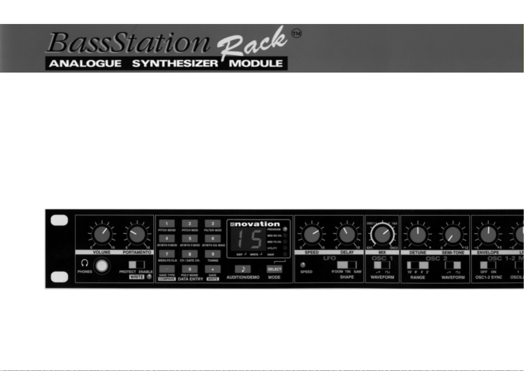
1 Master Volume Section
This section contains the Master Volume and Portamento controls, Headphone output
socket and the Program write enable switch.
2 Data Entry I Program Section
This section contains the 12 Data Entry buttons, Display and Menu LEDs,
Audition/Demo and Mode Buttons.
3 LFO Section
This section contains the LEO Speed, Depth and Waveform Shape controls.
4 Oscillator 1- 2 Sections
This section contains the Oscillator 1 Waveform, Oscillator 2 Waveform, Range,
Detune and Semi-tone transposition controls. It also contains the control to mix
Oscillators 1 & 2 with the external audio input.
5 Oscillator 1 & 2 Mod/Sync Section
This section contains the Oscillator 1-2 Sync, Oscillator Mod select, PWM Source,
Envelope Modulation, LEO Modulation and Pulse Width Depth controls.
6 Filter Section
This section contains the Frequency, Resonance, Modulation Depth, Cut-off slope and
Modulation Source controls.
7 Envelope Section
This section contains the Envelope select, Triggering, Attack, Decay, Sustain, Release
and Velocity controls.
FRONT PANEL
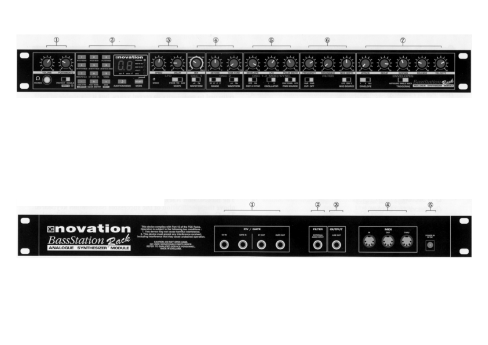
1 CV / Gate ln & Out
The connectors in this section are used to interface vintage analogue synthesisers
with CV / Gate in/outs to MIDI.
2 Filter Input
This connector is used to process an external MIDI triggered sound source through
the filter and envelope sections of the BassStation Rack.
3 Output
This 1/4 jack delivers a line-level output signal for connection to a mixing desk or
amplifier input.
4 MIDI
IN - This connector is used to receive MIDI data from an external device
OUT - This connector is used to transmit MIDI data to an external device.
THRU - This connector re-transmits MIDI data received by the MIDI IN socket to an
external device.
5 9vDC Input
Connect the output plug of the AC adapter supplied with the BassStation Rack to this
socket.
REAR PANEL
3
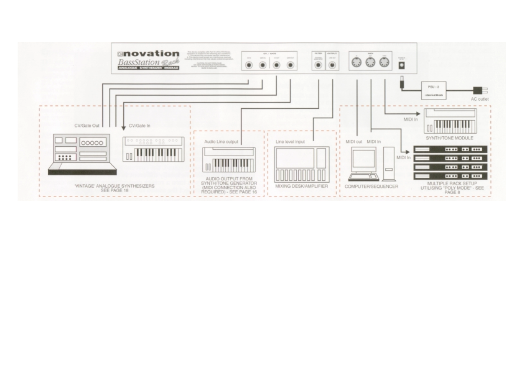
Connect the ‘Line out’ socket on the BassStation Rack to a suitable amplifier or mixing
desk and set the ‘Volume’ control to a reasonably high output level (9-10). This will
maintain a good signal to noise ratio on the line level output from the BassStation, but
be sure that the input volume setting on your amplifier or mixer is initially set at a low
level (to ensure a comfortable listening volume when the first notes are played ) and
then adjust accordingly. Connect the MIDI Out from your master keyboard or
sequencer to the MIDI In on the BassStation Rack and check that the ‘Write’ switch is
in the ‘Protect’ position. Now, connect the power supply ( Novation PSU-3 ) to the
socket marked ‘Power In 9VDC’ and plug into a suitable AC power outlet.
The Display should now illuminate showing the selected program number and the LFO
speed LED should be flashing at a constant rate. If this does not happen, check that
the power supply is of the specified type and that it is connected as described above.
Now you can use your master keyboard or sequencer to play the currently selected
sound (the BassStation Rack is initially set at the factory to receive on MIDI channel
1). To listen to all 40 factory presets, first make sure the ‘Program’ LED is on (if not,
use the ‘Mode’ button to re-select ) and then use the ‘Data Entry’ keypad to call up
sounds ‘00’ to ‘39’ - see page 5 and the separate sheet for factory program information. You can also use the ‘Audition’ button to trigger the sounds
The BassStation Rack also features a ‘Demo’ mode. To play the demo use the ‘Mode’
button to select ‘Utility’ (LED lit) and press the ‘Audition/Demo’ button. To stop the
demo. simply press the ‘Audition/Demo’ button again.
Reading the following chapter. "How the controls work" in detail. will help you to
understand how the sounds were created and allow you to explore the extensive sonic
capabilities of the BassStation Rack so you can easily create your own. individual
sounds.
CONNECTIONS
QUICK SETUP GUIDE
4
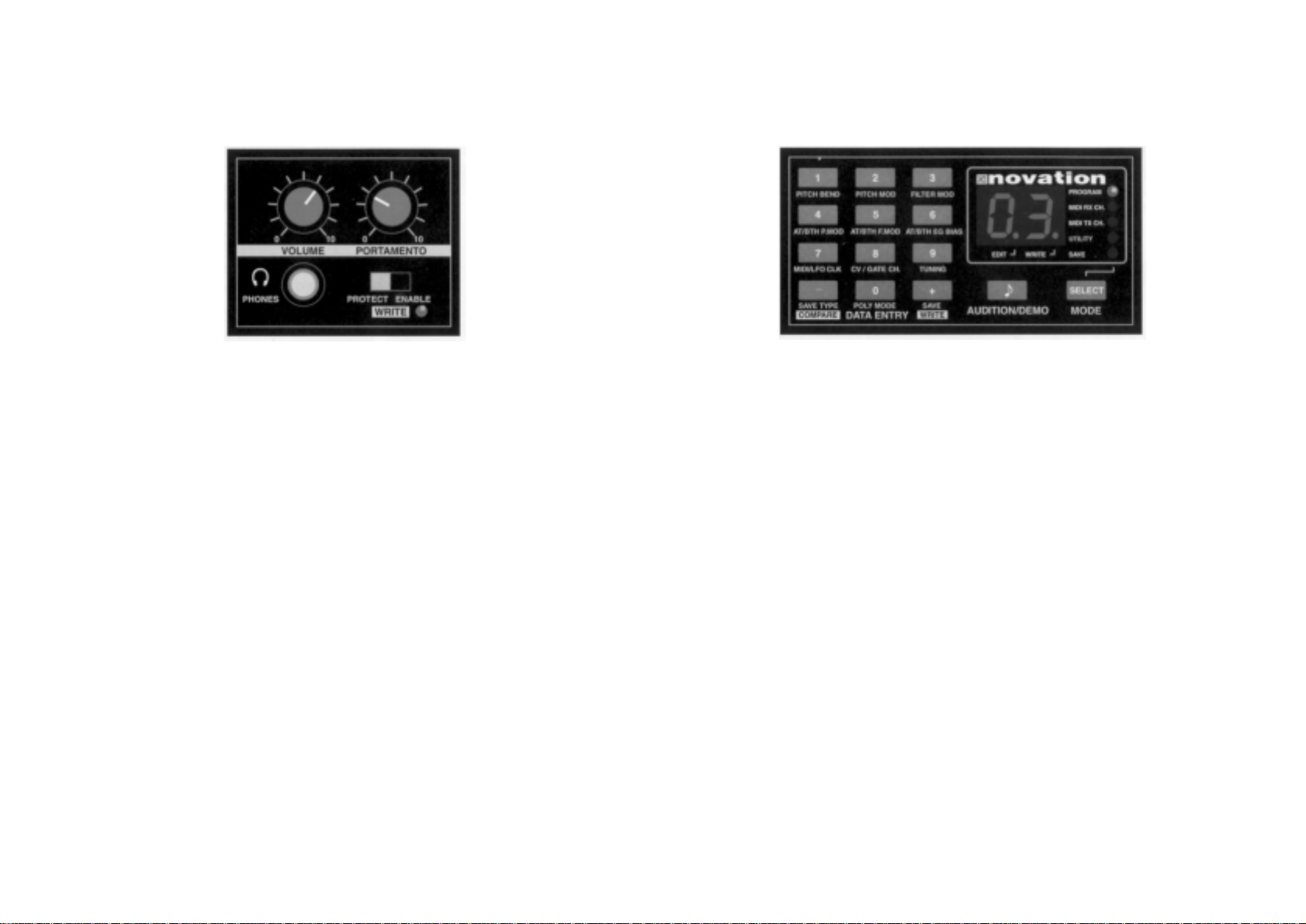
MASTER VOL SECTION
Volume - Rotary
This knob allows you to adjust the output volume of the BassStation Rack.
Turn to the left to reduce the volume and to the right to increase the volume.
This control affects both the Line level output on the rear panel and the
Headphone output on the front panel.
Portamento - Rotary
This knob controls the speed of the glide between the last pitch and the next. All the
way to the left, the pitch changes instantaneously so you will not hear any glide. As
you move the knob to the right, the time taken for the pitch to change between notes
is increased and you begin to hear the glide. At the far right, this takes 5 seconds. The
position of this knob is saved with each sound.
Write - Switch
This switch protects your sounds from accidental erasure. During normal operation it
should be left in it’s ‘Protect’ position however, when you have edited or created a new
sound that you want to save, moving it to the ‘Enable’ position will allow you to "write"
over an existing sound - see "Writing a Program Into Memory" on page 10.
Headphone - Socket
Use this 1/4 jack socket to monitor the output of your BassStation Rack via headphones. This output will drive any type of headphones.
DATA ENTRY / PROGRAM SECTION
This is where you select the sounds you have previously created on the BassStation Rack, set the MIDI
transmit and receive channels, set the various utility
functions and store newly edited sounds. When editing
a stored sound, the current position of a knob or
switch will probably be totally different to that of the
memory sound selected, so when you turn a rotary
control more than a few degrees or move a switch
expect the sound to "ping" to the new position.
Mode -Button
This button is used to select which of the five main parameter ‘Modes’ are accessed
by the ‘Data Entry’ keypad. The current mode is indicated by one of five LED’s on the
right hand side of the display panel. NOTE: When the BassStation Rack is switched
on, ‘Program’ mode is automatically selected. Each time the Mode button is pressed
the next ‘Mode’ in the menu will be selected i.e. MIDI RX Channel, MIDI TX Channel,
Utility and Save. From ‘Save’, the next press will loop the menu back up to the
‘Program mode’.
Audition/Demo - Button
This button is used to trigger a note from the currently selected sound. It provides a
convenient way of monitoring a sound whilst working at the control panel. The triggered note can also be transpo~ed up or down to suit the sound (higher notes for lead
sounds, lower notes for bass ) as follows:
HOW THE CONTROLS WORK

5
DATA ENTRY / PROGRAM SECTION CONT.
1. Press and hold down the Audition button - note sounds once.
2. Press the ‘+‘ button on the Data Entry’ keypad - note sounds once + 1/3 octave. (
Each time the ‘+‘ button is pressed the note will sound and move up 1/3 octave)
3. Press the ‘-‘ button on the ‘Data Entry’ keypad - note sounds once - 1/3 octave.
(Each time the ‘-‘ button is pressed the note will sound and move down 1/3 octave)
When you are happy with the transposition of the note, release both buttons. To check
the note again simply press the ‘Audition’ button.
NOTE: The transposition setting is not saved with each sound. For information on the
‘DEMO’ mode, see page 9.
Data Entry Keypad - Buttons
The 12 buttons of the ‘Calculator style’ Data Entry keypad are used to call up and set
the various operating parameters of each ‘Mode’ function. You can use two methods
to enter a number:
I. DIGIT INPUT - using the buttons 0 to 9.
Note: this must always be a two digit entry, for example:
Selecting program sound 8 press the ‘0’ and ‘8’ buttons - display reads ‘08’.
Selecting program sound 47 press the ‘4’ and ‘7’ buttons - display reads ‘47’.
2. INCREMENT/DECREMENT - using the ‘-‘ and ‘+‘ buttons.
Press the ‘+‘ button to move up to the next program or value.
Press the ‘-‘ button to move down to the next program or value.
These buttons can also be used to ‘scroll’ through values by pressing and
holding down until the desired value is reached.
Mode 1-Program Change
This is where you select a sound from the BassStation’s 100 programs. The ‘Program
Change’ mode is automatically selected when the BassStation Rack is powered up
and the program number displayed will be the one selected prior to power being
turned off. To select a different sound. first check that the ‘PROGRAM’ LED is on.
Using the ‘Data Entry’ keypad as described above, you can quickly call up any of the
BassStation’s programs. The recognised numbers in this mode are from ‘00’ to ‘99’.
You can also use MIDI Program Change commands from a sequencer or other external MIDI device to call up sounds. NOTE: Because the Rack’s programs begin at ‘00.
the next higher number must
always be used to call up the correct sound. i.e. to select Rack program 88,
transmit a MIDI Program Change 89.
NOTE 2: The 40 factory sounds are stored in programs 00’ to ‘39’ whilst the 60
user locations from ‘40’ to ‘99’ are all initially stored with a basic square wave
tone - see separate sheet for program listing.
Mode 2-MIDI Receive Channel
This is where you set the MIDI receive channel for the BassStation Rack. Use the
‘Mode’ button to select the ‘MIDI RX Ch.’ mode - LED on, and then the ‘Data Entry’
keypad to enter your selection. The recognised numbers in this mode are from ‘01’ to
‘16’.
NOTE: the ‘MIDI RX CH.’ LED will flash when MIDI data is received on this channel.
Mode 3-MIDI Transmit Channel
This is where you set the MIDI transmit channel for the BassStation Rack. Use the
‘Mode’ button to select the ‘MIDI TX Ch.’ mode - LED on, and then the ‘Data Entry’
keypad to enter your selection. The recognised numbers in this mode are from ‘01’ to
‘16’. NOTE: The MIDI Tx and Rx channels are memorized even when the power is
turned off.
Mode 4-Utility
This is where you set the various Utility functions of the BassStation Rack. Use the
‘Mode’ button to select the ‘UTILITY’ mode - LED on.
NOTE: the operating system of the ‘Data Entry’ keypad is slightly different in this mode
( all of the functions in the Utility mode are visually indicated by yellow text - see panel
diagram ). The ‘0’ to ‘9’ buttons are now used to call up sub-directories’ of the Utility
mode and the ‘-‘ and ‘+‘ buttons used to change their values whilst the display will
flash alternatately between a value and a letter reference code. The ten sub-directories of the Utility mode are as follows:
Button Function Display Ident. Range
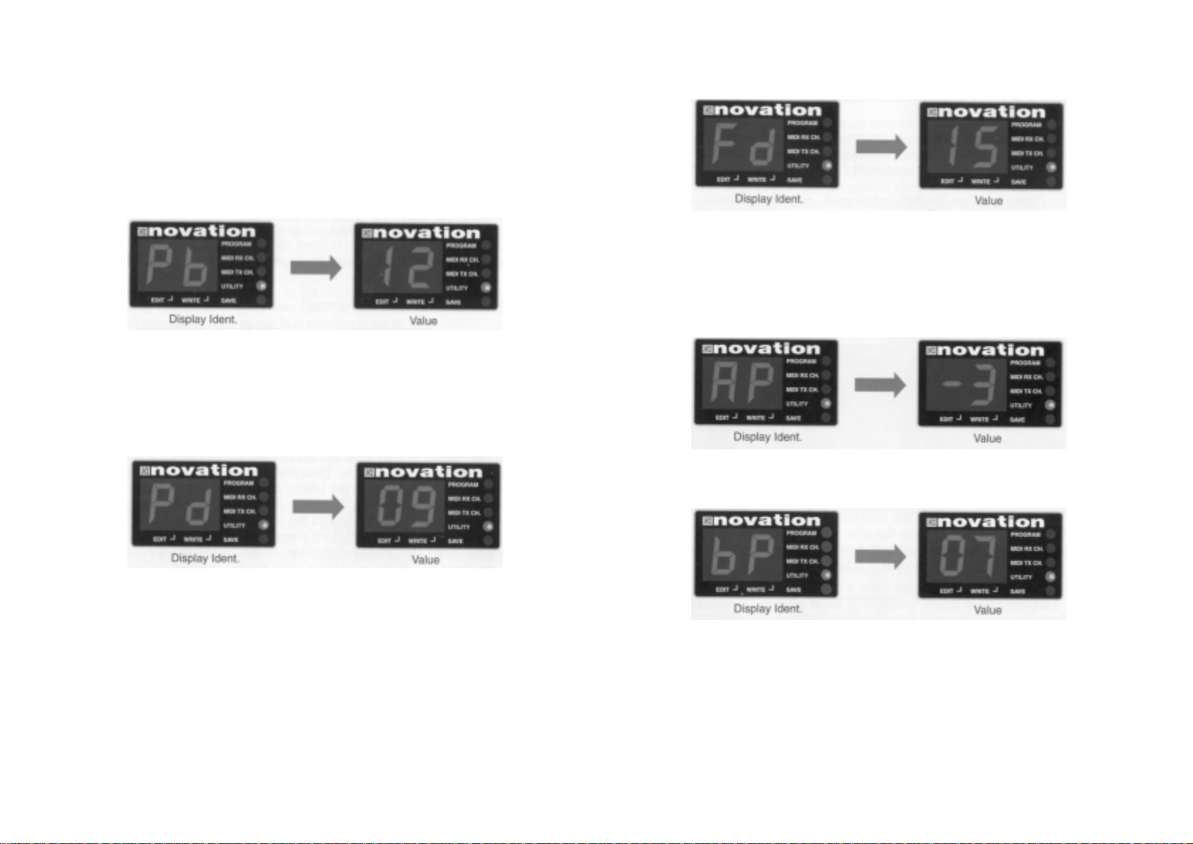
1 Pitch bend range P b ‘00’ to ‘12’
2 Pitch mod depth P d ‘00’ to ‘15’
3 Filter mod depth F d ‘00’ to 15’
4 Aftertouch/Breath pitch mod depth A P / b P ‘~7’ to ‘07’
5 Aftertouch/Breath filter mod depth A F / b F ‘-7’ to ‘07’
6 Aftertouch/Breath envelope generator bias A E/ b E ‘00’ to ‘15’
7 MIDI to LFO clock rate L F ‘00’ to ‘96’
8 CV/Gate MIDI channel/Type OH/Ct ‘01’ to ‘16’/’00’ to ‘02’
9 Tuning Tn ‘-9’to’09’
0 Polyphonic Mode P L ‘OF’ & ‘On’
HOW THE CONTROLS WORK
6
DATA ENTRY / PROGRAM SECTION CONT.
Pitch Bend Range
This is where you set the semitone range response br the pitch bend wheel of an external
keyboard. Each number represents a semitone i.e. bend range ‘02 = two semitones. bend
range 12’ = twelve semitones ( one octave ). Press the ‘PITCH BEND button once - the display alternates between:
Use the ‘-‘ and ‘+‘ buttons to change the value. This setting can be saved with the sound see ‘Writing a program into memory’ on page 10.
Pitch Mod Depth
This is where you set the amount ( depth ) of pitch modulation from the Controller wheel of
an external keyboard. Range = ‘00’ (off) to ‘I 5’(rnaxirnum). Press the ‘PITCH MOD’ button
once - the display alternates between:
Use the ‘-‘ and ‘+‘ buttons to change the value. This setting can be saved with the sound see ‘Writing a program into memory’ on page 10.
Filter Mod Depth
This is where you set the amount of filter modulation from the Controller wheel of an external keyboard. Range = ‘00’ (off) to ‘15’(maximum). Press the ‘FILTER MOD’button once the display alternates between:
Use the ‘-‘ and ‘+‘ buttons to change the value. This setting can be saved with the sound see ‘Writing a program into memory’ on page 10.
Aftertouch I Breath Pitch Mod Depth
This dual function button is used to set the amount of pitch modulation for either Aftertouch
or Breath ( MIDI wind controllers ). Range = ‘-7’ to ‘+07’. Press the ‘AT/BTH P.MOD ‘ button
once - the display alternates between:
Use the ‘-‘ and ‘+‘ buttons to change the value. This setting can be saved with the sound.
Press the ‘AT/BTH P.MOD’ button again - the display will now alternate between:
Use the ‘-‘ and ‘+‘ buttons to change the value. This setting can be saved with the sound see ‘Writing a program into memory’ on page 10.
HOW THE CONTROLS WORK
 Loading...