

Novation Bass Station II User Manual
1
Novation
A division of Focusrite Audio Engineering Ltd.
Windsor House,
Turnpike Road,
Cressex Business Park,
High Wycombe,
Bucks,
HP 12 3FX .
United Kingdom
Tel: +44 1494 462246
Fax: +44 1494 459920
e-mail: sales@novationmusic.com
Web: http://www.novationmusic.com
ENVIRONMENTAL
D E C L A RAT IO N
Compliance Information Statement: Declaration of Compliance procedure
Product Identification: Novation Bass Station II keyboard
Responsible party: American Music and Sound
Address: 4325 Executive Drive,
Telephone: 800-431-2609
Suite 300
Southaven,
MS 38672
Trademarks
The Novation trademark is owned by Focusrite Audio Engineering Ltd. All other br and,
product and com pany names and any other regi stered names or trade marks mentioned in
this manual belong to their respective owners.
Disclaimer
Novation has taken all possible steps to ensure that the information given here is both
corre ct and complete. I n no event can Novatio n accept a ny liability or re sponsibility for
any loss or damage to the owner of the equi pment, any third party, or any equipment
which may result from use of this manual or the equipment which it describes. The
information provided in this document may be modified at any time without prior warning.
Specifications and appearance may differ from those listed and illustrated.
IMPORTANT SAFETY
INSTRUCTIONS
1. Read these instructions.
2. Keep these instructions.
3. Heed all warnings.
4. Follow all instructions.
5. Do not use this apparatus with water.
6. Clean only with dry cloth.
7. Do not install near any heat sources such as radiators, heat registers, stoves, or other
apparatus (including amplifiers) that produce heat.
8. Do not d efeat the safety purpose of the polarized or grounding-type plug. A pol arized
plug has two blad es with one wider than the other. A grounding type plug has t wo blades
and a third grounding prong. The wide blade or the third prong are p rovided for your safety.
If the provided plug does not fit into your outlet, consult an electrician for replacement of
the obsolete outlet.
9. Protect the power cord from being walked on or pinched particularly at plugs,
convenience receptacles, and the point where they exit from the apparatus.
10. Only use attachments /accessories specified by the manufacturer.
11.
12. Unplug this apparatus during lightning storms or whe n unused for long periods of time.
13. Refer all servicing to qualified service personnel. Servicing is required when the
appar atus has been damaged in any way, such as power-supply cord or plug is damaged,
liquid has been spilled or objects have fall en into the a pparatus, the apparatus has been
exposed to rain or moisture, does not operate normally, or has been dropped.
14. No naked flames, such as lighted candles, should be placed on the apparatus.
WARNING: Excessive sound pressure levels from earphones and headphones can cause
Use only with the cart, st and, tripod, bracket, or table specified by the
manufacturer, or sold with the apparatus. When a car t is used, use
caution when moving the cart/apparatus combination to avoid injury
from tip-over.
hearing loss.
This device complies with part 15 of the FCC Rules. Operation is subject to the foll owing
two conditions: (1) This device may not cause harmful interference, and (2) this device
must accept any interference received, including inter ference that may cause undesired
operation.
For USA
To the User:
1. Do not modify this unit! This product, when installed as indicated in the instructions
contained in this manual, meets F CC requirements. Modificati ons not expressly
approved by Novation may void your authority, granted by the F CC, to use this product.
2. Important: This product satis fies FCC regulations when high quality shielded USB
cables with integral ferrite are used to connect with other equipment . Failure to use high
quality shielded USB cables with integral ferrite or to follow the installation instructions
within this manual may cause magnetic inter ference with ap pliances such as radios and
televisions and void your FCC authorization to use this product in the USA .
3. Note: This equipment has been tested and found to comply with the limits for a Cla ss
B digital device, pursu ant to par t 15 of the FCC Rules. These limits are designed to
provide reasonable protection against harmful interference in a residential installation.
This equipment generates, uses and can radiate radio frequency energy and, if not
installed and used in accordance with the instructions, may cause harmful interference
to radio c ommuni cations. However, there is no guarantee that inte rfere nce will not occur
in a particular installation. If this equipment does cause harmful inter ference to radio
or television reception, which c an be determined by turning the equipment off and on,
the user is encouraged to tr y to correct the interference by one or more of the following
measures:
• Reorient or relocate the receiving antenna.
• Incre ase the separation between the equipment and receiver.
• Connect the equipment into an outlet on a circuit different from that to which the
receiver
is connected.
• Consult the dealer or an experienced radio/ TV technician for help.
For Canada
To the User :
This Class B digital apparatus complie s with Canadian ICES-003.
Cet appareil numérique de la cla sse B est conforme à la norme N MB-003 du Canada.
RoHS Notice
Novation has conformed and product conforms, where applicable, to the European
Union’s Directive 2002/ 95/ EC on Restrictions of Hazardous Substa nces ( RoHS) as
well as the following sections of California law whic h refer to RoHS, namely sections
25214.10, 25214.10.2, and 58012, Health and Safety Co de; Section 42475.2, Public
Resources Code.
WARNING: This equipment must only be connec ted to USB 1.1 or 2.0 type ports.
CAUTI ON: TO REDUCE THE RIS K OF
ELECTRIC SHOCK, D O NOT REMOVE
COVER ( OR BACK). NO USER-SERVICABLE
PARTS INSIDE. REFER SERVI CING TO
QUALIFIED SERVICE PERSONNEL .
The lightning flash with arrowhead symbol within an equilateral triangle is
intended to aler t the user to the presence of uninsulated “dangerous voltage”
within the product’s enclosure that may be of sufficient magnitude to constitute
the risk of electric shock to persons.
The exclamation point within an equilateral triangle is intended to alert the use r
to the presence of important operating and maintenance (servicing) instructions
in the literature accompanying the appliance.
WARNING: TO REDUCE THE RIS K OF FIRE OR ELECTRIC SH OCK, DO NOT EXPOSE
THIS A PPARATUS TO RAIN OR MOISTURE .
2
CAUTION:
The nor mal operation of this product may be affected by a strong electrostatic discharge
(ESD). In the event of this happening, simply reset the unit by removing and then
replugging the USB cable. Normal operation should return.
COPYRIGHT AND LEGAL
NOTICES
Novation is a registered tr ade mark of Focusrite Audio Engineering Limited.
Bass Station II is a trade mark of Focusrite Audio Engineering Limited.
2013 © Focusrite Audio Engineering Limited. All rights reserved.

CONTENTS
IMPORTANT SAFETY
INSTRUCTIONS ..............................................................2
ENVIRONMENTAL
DECLARATION...............................................................2
For USA .................................................................2
For Canada ..............................................................2
COPY RIGHT AND LEGAL NOTICES............................................2
INTRODUCTION..............................................................4
Key Features .............................................................4
About T his Manual ........................................................4
What’s In The Box .........................................................4
Registering your Bass St ation II .............................................4
Power Requirements ......................................................4
Hardware Overview .......................................................5
GETTING STARTED...........................................................7
Loading Patches ..........................................................7
Saving Patches ...........................................................7
Basic Operation – sound modific ation .......................................7
The LED display ....................................................7
The Filter knob......................................................7
Pitch and Mod wheels . . . . . . . . . . . . . . . . . . . . . . . . . . . . . . . . . . . . . . . . . . . . . . .7
Octave Shift........................................................7
Transpose .........................................................8
On-Key functions ...................................................8
Local control .......................................................8
SYNTHESIS TUTORIAL........................................................8
Pitch ..............................................................8
Ton e ..............................................................8
Volume ............................................................8
The Osc illator s And Mixer ............................................9
Sine Waves ........................................................9
Triangle Waves .....................................................9
Sawtooth Waves....................................................9
Squar e / Pulse Waves ...............................................9
Noise .............................................................9
Ring Modulation ....................................................9
The Filter ........................................................10
Envelopes And Amplifier ...........................................10
Attack Time .......................................................11
Decay Time .......................................................11
Sustain Level......................................................11
Release Time......................................................11
LFOs.............................................................11
Summary .........................................................11
SIMPLIFIED BASS STATION II BLO CK DIAGRAM . . . . . . . . . . . . . . . . . . . . . . . . . . . . . . . 12
BASS STATION II IN DE TAIL ..................................................12
The Oscillator Section ....................................................12
Waveform........................................................ 12
Pitch ............................................................ 12
Modulation....................................................... 12
Pulse Width...................................................... 13
Oscillator Sync ...................................................13
The Sub Oscillator ................................................13
The Mixer Section........................................................13
The Filter Section ........................................................13
Filter type........................................................ 13
Frequency ....................................................... 14
Resonance....................................................... 14
Filter modulation.................................................. 14
Overdrive ........................................................14
The Envelopes Section ...................................................14
Portamento .............................................................15
The Effects Section ......................................................15
The LFO Section.........................................................15
LFO 1:........................................................... 15
LFO 2: .......................................................... 15
LFO Waveform s .................................................. 16
LFO Speed ...................................................... 16
LFO Delay ....................................................... 16
LFO Speed/Sync ................................................. 16
LFO Keysync .....................................................16
LFO Slew........................................................ 16
The Arpeggiator Section ..................................................16
Arp Swing ....................................................... 17
The Sequencer ..........................................................17
Record .......................................................... 17
Play ............................................................. 17
SEQ Retrig ...................................................... 17
On-key Functions ........................................................17
APPENDIX ..................................................................19
Importing Patches via SysEx ...............................................19
Sync values table ........................................................19
Init Patch – parameter table ...............................................20
Synth settings saved on power-off ..........................................20
Synth settings not saved on power-off ......................................20
MIDI parameters list ......................................................21
MIDI implementation table.................................................21
3

INTRODUCTION
1
Thank you for purchasing this Bass Station II digitally-controlled analogue synthesizer.
Based on the classic 1990s Novation B ass Station synth, it combines traditional analogue
waveform generation and processing with the power and fl exibility of digital control, plus a
set of ef fects and presets for the 21st century.
NOTE: Ba ss Stati on II is capable of generating audio with a large dynamic range, the
extremes of which can cause damage to loudspeakers or other components, and also to
your hearing!
Key Features
• Classic analogue waveform generation
• Two multi-waveform oscillators plus separate sub oscillator
• Analogue signal path – fi lters, envelopes, modulation
• Traditional “single function” style rotary controls
• LP/BP/HP fi lters with variable slope
• Separate dual LFO section
• Ring Modulator (inputs: Oscs 1 and 2)
• Versatile 32-step arpeggiator with wide range of patterns
• 32-step sequencer with four memories
• Portamento with dedicated time control
• Pre-loaded with 64 brand new Killer Patches
• Memory for 64 additional User Patches
• Pitch and Mod wheels
• 25-note velocity-sensitive keyboard with aftertouch
• -5/+4 octave keyboard shift
• Key transpose function
• On-Key functions – use the keyboard to adjust non-performance sound parameters
• MIDI input and output
• LED display for patch selection, parameter adjustment, octave settings, etc.
• External DC input (for supplied AC PSU)
• Class-compliant USB port (no drivers required), for alternative DC power, patch
dump and MIDI
• External audio input to mixer section
• Headphone output
• Sustain pedal socket
• Kensington Security Slot
About This Manual
We’ve tried to make this manual a s helpful as possible for all types of user, and this
inevitably means that more experienced users will want to sk ip over certain parts of it, while
relative novices will want to avoid certain parts of it until they’re confi dent they’ve mastered
the basics.
What’s In The Box
Your Bass St ation II has been carefully packed in the factory and the packaging was
designed to withstand rough handling. Should the unit appear to have been damaged in
transit, do not discard any of the packing material and notify your music dealer.
If practical, save all the packing materials in case you ever need to ship the unit again.
Please check the list below against the contents of the packaging. If any items are missing
or damaged, contact the Novation dealer or distributor where you purchased the unit.
• Bass Station II synthesizer
• DC power supply unit (PSU)
• USB cable
• Registration card, also providing on-line access to:
• Loopmasters Sample Content
• Ableton Live Lite
• This manual
Registering your Bass Station II
It is important to register your Bass Station II on-line, using the Warranty Registration Card
provided. Apart from validating your manufacturer’s warranty, you w ill also then be able to
download the additional software that you are entitled to as a Bass Station II purchaser.
Follow the instructions on the Registration Card.
Power Requirements
Bass Station II is shipp ed with a 9 V DC, 500 mA power supply. The centre pin of the
coaxial connector is the positive (+ve ) side of th e supply. Bass Station II can either be
powered by this AC-to-DC mains adaptor, or by a USB connection to a computer. To
obtain the best possible audio performance from Bass Station II we recommend using the
supplied adaptor.
There a re two ver sions of the PSU, your Bass Station II will be supplied with the one
appropriate to your country. In some countri es the PSU comes with detachable ad aptors ;
use the one that fi ts your countr y’s AC outlets. When powering Bass Station II with the
mains P SU, please ensure that your local AC supply is within the range of voltages required
by the ada ptor – i.e., 100 to 240 VAC - BEFORE you plug it into the mains.
We strongly recommend that you only us e the supplied PSU. Using alternative PSUs will
invalidate your warranty. Power supplies for your Novation product can be purchased from
your music dealer if you have lost yours.
If the synth is powered via the USB por t, note that it will “go to sleep” if the host computer
goes into power save mode. The synth can be “woken-up” again by pressing any key;
however, this does not alter the p ower status of the computer.
However, there are a few general points that are useful to know about before you continue
reading this manual. We’ve adopted some graphical conventions within the text, which we
hope all types of user will fi nd helpful in navigating through the informati on to fi nd what they
need to know quickly:
Abbreviations, conventions, etc.
Where top panel controls or rear panel connectors are referred to, we’ve used a number
to cross-refer ence to the top panel diagram , and thus :
thus:
1
the rear panel diagram. (See page 5 and page 6).
We’ve used B OLD TEXT (or Bold Text) to na me top panel controls or rear panel
connectors; we’ve made a point of using exactly the same names as appear on the Bass
Station II. We’ve used SEVEN-SEGMENT DIGITS to denote numbers that appear on the top
panel LED display.
Tips
These do what it says on the tin : we include bits of advice, relevant to the
topic being disc ussed that should simplify setting up Impulse to do what
you want. It’s not mandator y that you follow them, but generally they
should make life easier.
These are additions to the text that will be of interest to the more
advanced user and can generally be avoided by the novice. They are
intended to provide a clari fi cation or explanation of a pa rticular area of
operation.
1
to cross-reference to
A word about laptops :
I f powering your Bass Station II via the USB connection you should be aware
that although the USB specifi cation agreed by the IT industry states that a
USB port should be able to supply 0. 5 A at 5 V, some computers - particularly
laptops – are unab le to supply this current. Unreliable operation of the synth
will result in such a case. When powering Bass Station II from a l aptop’s USB
port , it is strongly rec ommended that the laptop is p owered from AC mains
rather than its internal battery.
4
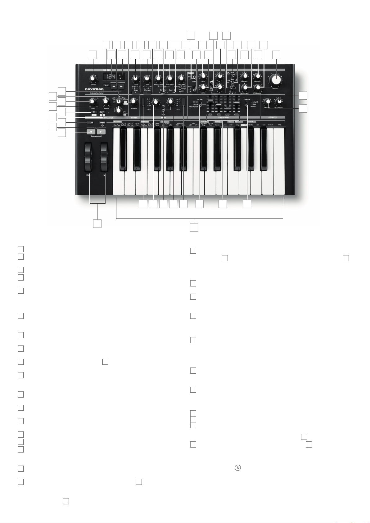
Hardware Overview
6
21 29 31
8 181247 13 1120
9 26 27 35 3732
610
7 15 14 16 17 19 22 28 33363430
45
44
43
46
41
42
4
5
3
2
25-note (two octaves) velocity-sensitive keyboard with aftertouch.
1
Pitch and Mod wheels: The Pitch wheel is mechanically biased to return to the centre
2
position when released. The wheels are internally illuminated.
Octave shift keys – transpose the keyb oard in octave increments .
3
Transpose - lets you transpose the keyboard in semitone incre ments, up to a maximum
4
of +/- 12 semi tones.
Function/Exit – hold this down to use any of Bass Station II’s On-Key Functions. A
5
wide ra nge of “system set-up” parameters can be set in this mode.
Master section:
LED display – a three-character alphanumeric display showing various items of unit
6
data – e.g., patch number, octave shif t and parameter values – depending on which
other controls are in use.
Org. Value – one of these two LEDs will illuminate when the value of a parameter no
7
longer matches the value stored for the patch.
Patch/Value – allows selection of one of the 64 Factory or 64 User Patches, and are
8
also used to set parameter values for On-Key functions.
Save – use in conjunction with Patch keys 8 to save modifi ed Patches in User
9
Memories.
Volume – sets the Bass Station II’s audio volume.
10
Oscillator sec tion:
Osc Sel ect switch – assigns the controls in the Oscillator section to Oscillator 1 or
11
Oscillator 2.
Range – steps through the base pitch ranges of the selected oscillator. For standard
12
conce rt pitch (A3 = 440 Hz), set to 8’.
Waveform – steps through the range of available oscillator waveforms – sine,
13
triangular, sawtooth and pulse.
Coarse – adjusts the pitch of the selected oscillator over a range of ±1 octave.
14
Fine – adjusts the oscillator pitch over a range of ±100 cents (±1 semitone) .
15
Mod Env depth – controls the degree by which the oscillator pitch ch anges as a
16
result of modulation by Envelope 2; the control is ‘centre-of f’, so that either pitch increases
or decreases can be obtained.
LFO 1 depth – controls the degree by which the oscillator pitch changes as a result of
17
modulation by LF O 1.
Pulse width modulation source – active only when Waveform 13 is set to Pulse; this
18
switch selects the method of varying the width of the pulse waveform. The options are:
modulation by Envelope 2 ( Mod Env), modulation by LFO 2 (LFO 2 ) or manual control by
the Pulse Width control
.
19
2324 38 39 4025 25 24
49
48
1
Pulse Width – a multi-functional control adjusting the pulse waveform; only active
19
when Waveform
is set to Manual, the control adjusts the pulse width directly ; when set to Mod Env or LFO
2, it acts as a Modulation Depth control. Note that the pulse width may be modulated by all
three sources simultaneously, by differing amounts.
Sync 1-2 – this LED illuminates when the Osc 1/Osc 2 Sync function is enabled ( an
20
On-Key Function)
Octave – sets the range of the sub-octave oscill ator; the actual pitch of this oscillator
21
is deter mined by OSC 1’s pitch, and adds additional bass frequencies (LF) to the sound. -1
adds LF one octave below OSC 1, -2 adds LF two octaves below.
Sub Osc Wave – a choice of three waveforms is available for the sub-octave oscillator:
22
sine, narrow pulse or square.
LFO section:
LFO Delay/Speed – the two rotary controls in the LFO section are dual-function,
23
the function being set by this switch. In Speed mode, the rotary controls adjust the
frequencies of the two LF Os. In Delay mode, they set the “ fade-in” time for the LFO.
Speed mode can be change d to Sync mode by using one of the On-key functions. See “
Mod Wh : Filter Freq (bottom C)” on page 17 for further information.
LFO waveform – these buttons step through the available waveforms for each LFO
24
independently: tria ngle, sawtooth, square, sample and hold . The associated LEDs give a
visual indication of the LFO speed and waveform.
LFO rotary controls – these two controls either adjust LFO s peed or delay, as set by
25
the LFO D elay/ Speed switch [23].
Mixer section:
OSC 1 – adjusts the proportion of Oscillator 1’s signal mak ing up the sound.
26
OSC 2 – adjusts the proportion of Oscillator 2’s signal making up the sound .
27
Sub – adjusts the proportion of the sub -octave oscillator making up the sound.
28
Additional inputs - up to three further sour ces may contribute to the synth output; this
control sets their levels . The control’s function is set by switch
Noise/Ring/Ext – determines the function of rotar y control 29. When set to Noise,
29
the rotary control sets the amount of white noise added to the sound; when set to Ring, it
sets the amount of the output from the Ring Modulator circuit is added (the i nputs to the
Ring Modulator are Osc 1 and Osc 2); in the Ext position, an external signal connected to
the rear panel connector
is set to Pulse. When the pulse width source modulation switch 18
13
.
30
6
can be mixed in.
5
Filter section:
Type – two-position switch selecting fi lter type: Classic confi gures a variable fi lter,
30
whose basic character istics may be set with the Shape and Slope switches
Acid confi gur es a 4-pole diode ladder lo-pass fi lte r, which emulates a type of fi lter found on
early ‘80s analogue synths.
Shape – three-position switch; with Type set to Classic, sets the fi lter characteristic
31
to be lo-pass (LP), band-pass (BP) or hi-pass ( HP).
Slope – two-position switch; with Type set to Classic, sets the slope of fi lter beyond
32
the pas sband to either 12d B or 24dB per octave.
Frequency – large rotary knob controlling the fi lter’s cut-off frequency ( LP or HP ), or
33
its centre frequency (BP).
Resonance – adds resonance (an increased response at the fi lter frequency) to the
34
fi lter characteristic.
Overdrive – adds a degree of pre-fi lter distor tion to the mixer output.
35
Mod Env depth – controls the degree by which the fi lter frequency is modifi ed by the
36
Mod Envelope.
LFO 2 depth – contro ls the degree by which the fi lter frequency is modifi ed by LFO 2.
37
Envelopes Section:
Env Select – assigns the Envelope faders [40] to var y the parameter s of the
38
Amplitude Envelope (Amp Env), Modulation Envelope (Mod Env), or both simultaneously
(Amp+Mod Env).
Envelope controls – a set of four faders adjusting the standard ADSR Envelope
39
parameters (Attack, Dec ay, Sustain and Release ).
Triggering – three-position switch controlling how envelopes work with legato and
40
portamento playing styles.
and 33;
32
Arpeggiator section:
On/Legato – turns the arpeggiator on and off. Also allows notes in a recorded arp
41
sequence to be tied, or played in a Legato style.
Latch/Rest – sets the arpeggiator to play the current pattern continuously. Also
42
allows a musical rest to be inserted in an arp sequence. When the arpeggiator is of f, the
Latch /Rest button enables a Key Hold function, which simulates the effect of holding a key
down continuously, until another key is pressed.
Temp o – sets the arp pat tern tempo in the range 40 to 240 BP M.
43
Rhythm – selects one of 32 pre-defi ned arp r hythmic patterns. The L ED display
44
indicates the pattern number.
Arp Mode – the arp c an play the notes mak ing up the selected pattern in a variety of
45
sequences; A rp Mode sets the sequence, and can also put the arp into Record and Play
modes for patterns based on the notes actually played rather tha n on the pre -defi ned
sequences.
Arp Octaves/SEQ – 4-position rotary switch setting the number of octaves over
46
which the arp pat tern plays. This control also selects one of four global sequences when
Arp Mode is set to Play or Record.
Portamento section:
Glide Time – sets the portamento glide time; with the control fully anticlockwise,
47
portamento is ‘off’.
Effects section:
Distortion – controls the amount of p ost-fi lter distortion added to the synth output.
48
Osc Filter Mod - allows the fi lter frequency to be modulated directly by Oscillator 2.
49
8
7
6
5
4
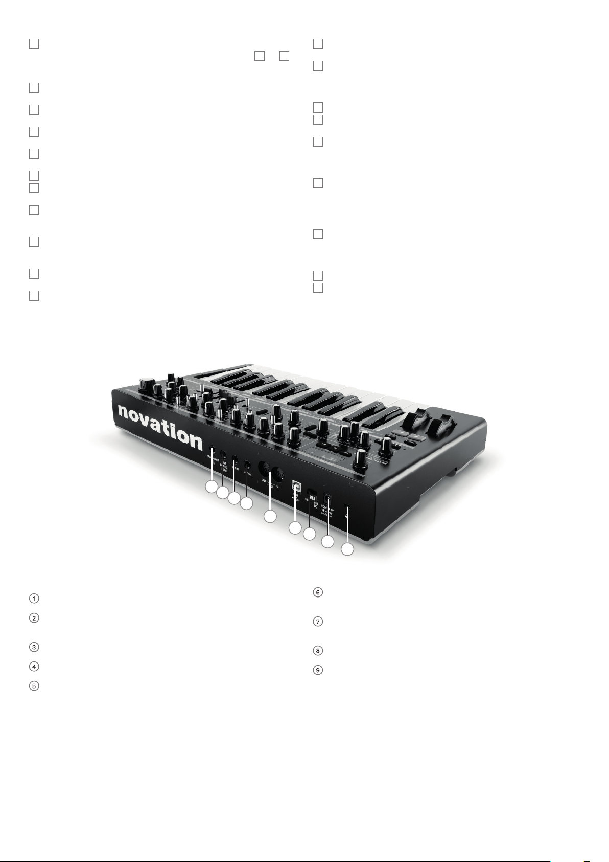
1
POWER IN – connect the supplied PSU here when powering Bass Station II from AC
mains.
2
Power switch – three-position switch: centre is OFF, set to ext DC if using the
supplied AC mains PSU, set to USB if powering Bass Station II from a computer via a
USB cable.
3
USB – standard USB 1.1 port (2.0-compatible). Connect to a Type A USB por t on a
computer using the supplied cable.
4
MIDI IN and OUT – standard 5-pin DIN MIDI sockets for connecting Bas s Station II to
other MIDI-equipped hardware.
5
S US TAIN – 2-pole ( mono) ¼” jack socket for connection of a sustain pedal . Both N/O
(Normally O pen) and N/C (Normally Cl osed) pedal types are compatible; if the pedal
is connected when the Bas s Station II is powered on, the type will be autom atically
sensed during boot-up (provided your foot is not on the pedal! ).
3
2
1
9
6
E XT IN – ¼” jack socket for external microphone, instrument or line level audio inputs.
Input is unbala nced. An audio source connected here may be mi xed with the synth
sound.
7
LINE OUTPUT (MONO ) – ¼” jack soc ket carr ying the Bass Station II ’s output s ignal ;
connect your recording system, amplifi er and speakers, audio mixer, etc. Output is
unbalanced.
8
HEADPHONES – 3-pole ¼” jack socket for stereo headphones (though synth output
is mono ). Phones volume is adjusted by the VOLUME control [10] .
9
Kensington Security Slot – to secure your synth.
6
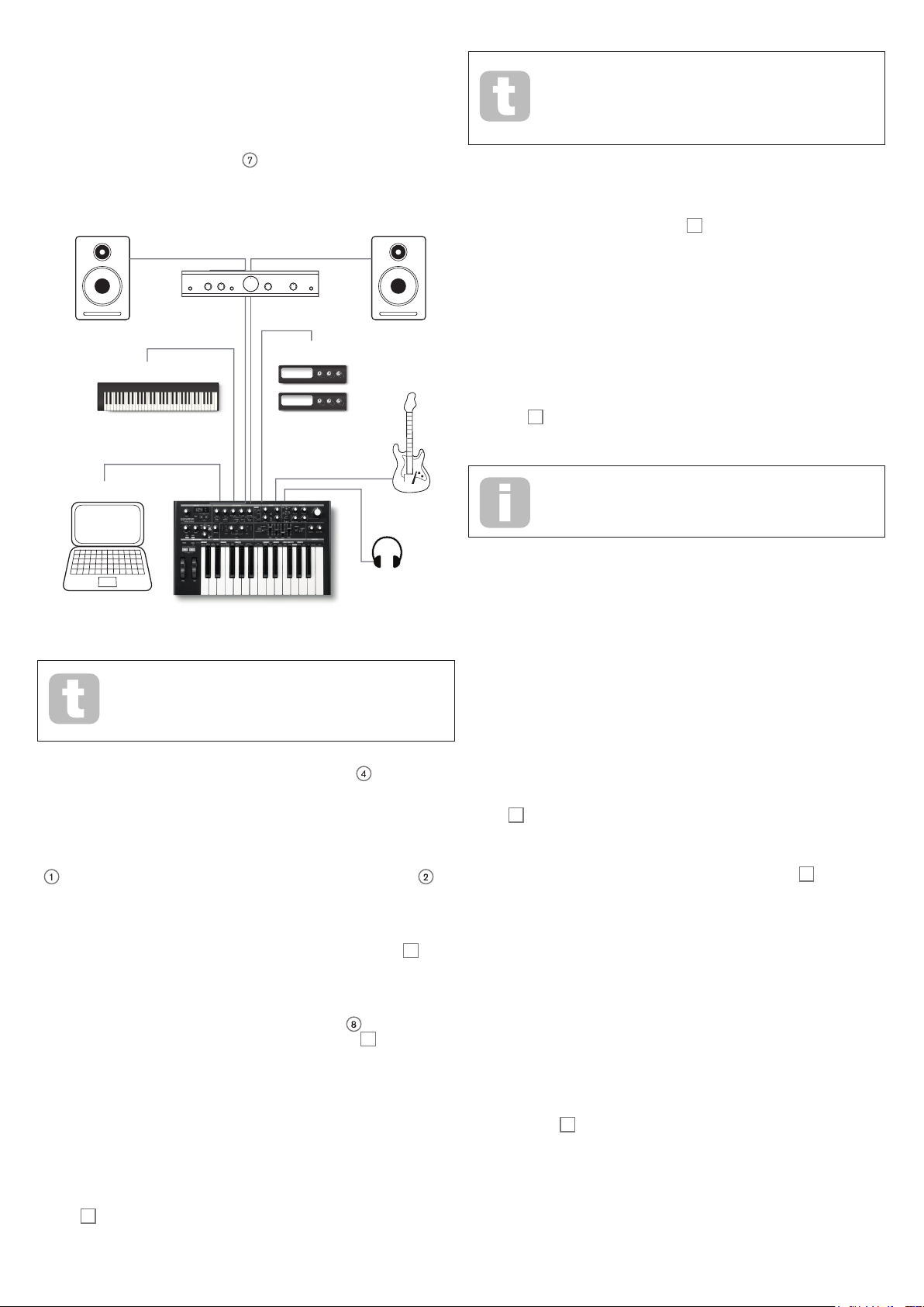
G E T TI NG S TAR TE D
Bass Station II may be used as a standalone sy nthesizer, or with M IDI connections to/
from other sound m odules or keyboards. It may also be connected - via its USB port – to a
computer (Windows or Mac). The USB connection can supply power to the synth, transfer
MIDI data to/from a MIDI sequencer a pplication and a llow Patches to be saved to memor y.
The sim plest and quickest way of get ting sta rted with Bass Station II is to conne ct the
rear pa nel jack socket marked LINE Output
mixer, powered speaker, thir d-par ty computer sound card or other means of monitoring the
output.
MIDI In
7
to the input of a power amplifi er, audio
Audio Out
MIDI Out
Note that when you change Patch, you lose the current synt h setting s. If
the current settings were a modifi ed version of a stored Patc h, these
modifi cations will be lost. Thus it is always adv isable to save your
settings before loading a new patch. See Saving Patches below.
Saving Patches
Patches can be saved to any of the 128 memory locations (0 – 127), but remember that
if you save your settings to any of Patches 0 - 63, you will overwrite one of the factory
presets. To save a patch press the Save button
patch number - will fl ash. To overw rite this Patch with your current settings, press the Save
button again. The LED display will briefl y indicate that the patch is being saved.
To save the current settings to a different memor y to the Patch number on the display
(as would be the case if you loaded a Patch, modifi ed it in some way and then wished to
save the modifi ed version without overwriting the original version), press the Save button
and then use the Patch buttons to select an alternative Patch memor y while the display is
fl ashing. Once se lected, it is possible to audition the target patch (by using the keyboard )
just to ma ke sure that you are happy to overwrite it. Press the Save button once more to
store the patch. The LED display will b riefl y indicate that the patch is being saved.
9
. The LED display – showing the current
Master Keyboard
USB
Note: Bass Station II is not a computer MI DI inter face. MIDI can be
transmitted b etween the synth and computer via the U SB connection, but
MIDI cannot be transferred between the computer and external equipment
via Bass Station II’s MIDI DIN ports .
If using Bass Station II with other sound modules, connect MIDI OUT
to MIDI IN on the fi rst sound module, and daisy-cha in further modules in the usual way. If
using Bass Station II with a master keyboard, conne ct the master keyboard’s MI DI OUT
to MIDI IN on the synth, and ensure that the master key board is set to output on MIDI
channel 1 (the synth’s default channel).
Sound Modules
Audio In
Headphones
4
on the synth
You can abor t the Save procedure at the “LED fl ashing” stage by pressing the Function/
Exit button
being edited.
5
. The Save procedure will cancel and Bass Station II will return to the patch
T he Bass Station I I Factor y Patches can be dow nloaded from the Novation
website if they have b een accidentally overwritten. See “I mporting Patches
via SysEx” on page 19.
Basic Operation – sound modifi cation
Once you have loaded a Patch you like the sound of, you can modify the sound in many
different ways using the synth controls. Each area of the control panel is dealt with in
greater depth later in the manual, but a few funda mental points should be discussed here:
The LED display
The three-segment alp hanume ric display will normally show the number of the currentlyloaded Patch (0 to 127). As soon as you change any “analogue” parameter – i.e., turn a
rotar y control or adjust an On-Key functi on, it will display the parameter value (most are
either 0 to 127 or -63 to +63), with one of two arrows being highlighted ( at the right-hand
side). These arrows indicate which direction the control needs to be turned in order to
match the value stored in the patch. It reverts to the Patch number display afte r the control
is released.
The Filter knob
Adjusting the frequency of the synth’s fi lter is probably the most commonly-used method of
sound modifi cation. For this reason, Filter Frequency has i ts own dedicated large rota ry
34
control
changing the fi lter frequency alters the characteristic of different types of sound.
at the panel top right. Exp eriment with dif ferent types of patch to hear how
With the amplifi er or mixer off or muted, connect the AC adaptor to the B ass Station II
1
, and plug it into the AC mains. Turn the synth on by moving the rear panel switch
ext DC. After co mpleting its boot sequence, Bass Station will load Patch 0, and the LCD
display will confi rm this. For a list of initial synth settings which are not retained from the
previous session, please see Synth settings unsaved from previous session in Appendix.
Turn on the mixer/amplifi er/powered speakers, and turn up the VO LUME control
you have a he althy sound level from the speaker when you play.
Using headphones
Instead of a speaker and /or an audio mixer, you may wish to use a pair of headphones.
These may be plugged into the rear panel headphone output socket
are still active when headphones are plugged in. The VOLUME control
headphone level.
NOTE: The Bass St ation II headphone amplifi er is capable of outputting a high signal level;
please take care when setting the volume.
8
. The main outputs
10
10
until
also adjusts
2
to
Loading Patches
Bass Station II can store 128 Patches in memory. 0 – 63 are pre-loaded with some great
factor y sounds. 64 – 127 are intended for storing user Patches, and are all pre-loaded with
the sam e default “initial” Patch ( see “Init Patch – paramete r table” on page 20).
A Patch is loaded by simply scrolling up or down to the Patch number with the Patch
8
buttons
number. The Patch buttons can be held down for fas t scrolling.
; the Patch is immediately active and the LED display shows the current patch
Pitch and Mod wheels
Bass Station II is fi tted with a standard pair of synthes izer control wheels
the keyboard, Pitch and Mod (Modulation ). The Pitch control is spring-loaded and always
returns to the centre position.
Moving Pitch will always raise or lower the pitch of the note(s ) being played. The maximum
range of operation is 12 semitones up or down, but this may be adjusted using On-Key
function Oscillator: Pitch Bend Range (Upper C#).
The Mod wheel’s precise function varies with the patch loaded; it is used in ge neral to add
expression or various elements to a synthesized sound. A common use is to add vibrato to
a sound.
It is possible to a ssign the Mod wheel to alter various parameters making up the sound
– or a combination of parameters simultaneously. This topic is discussed in more detail
elsewhere in the manual. See ‘On-key functions (mod wheel) on page 17.
Octave Shift
These two buttons
pressed, to a ma ximum of four octaves downwards, or fi ve octaves upwards. The number
of octaves by which the keyboard is shifted is indicated by the LED display. Pressing both
buttons together (Reset) returns the keyboard to its default pitch, where the lowest note on
the keyboard is one octave below Middle C.
3
transpose the keyboard up or down one octave each time they are
2
adjacent to
7
 Loading...