

Page 1
OPERATING INSTRUCTIONS
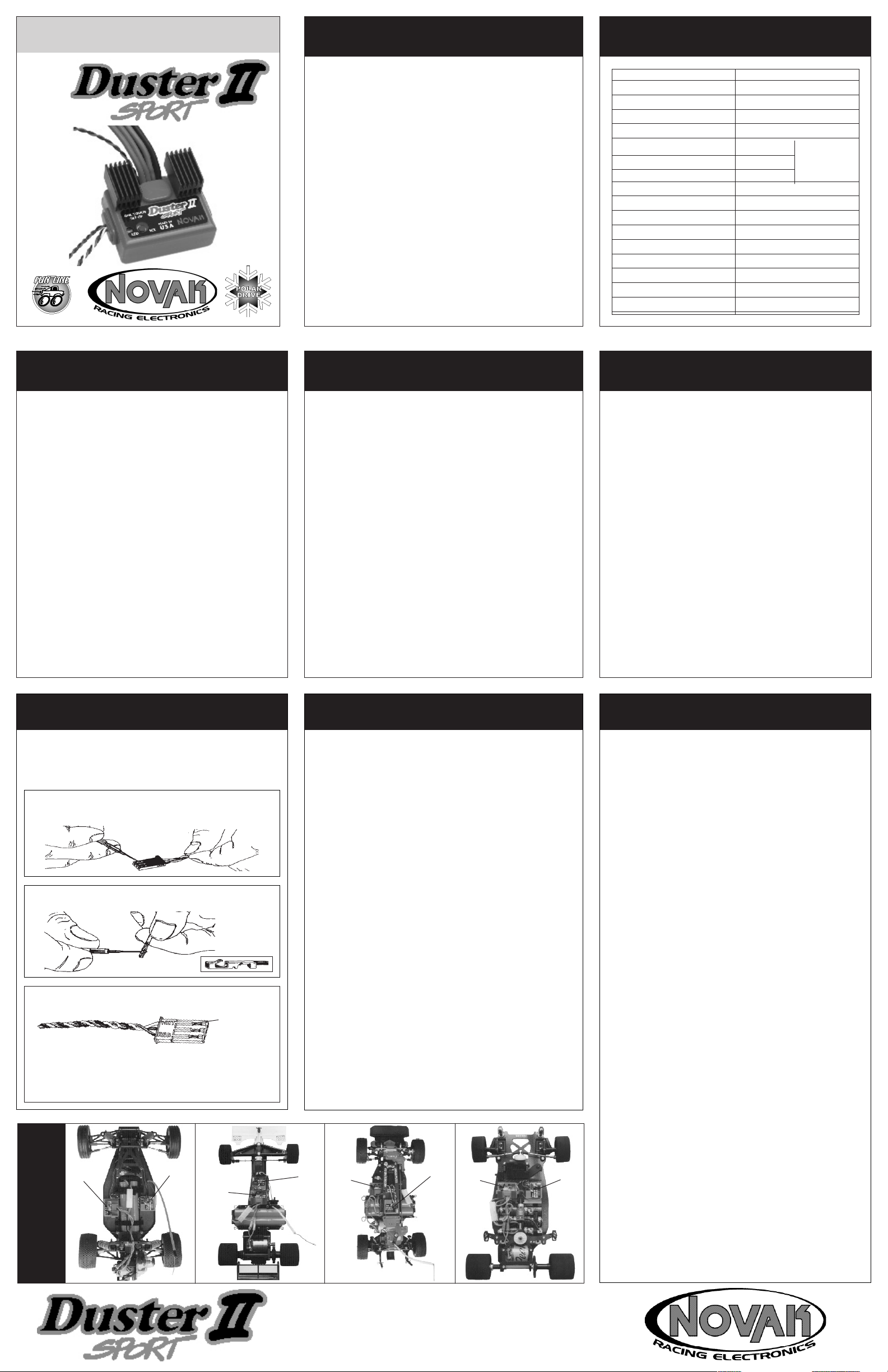
INTRODUCING THE DUSTER II
SPECIFICATIONS
HYPERFET II ESC
PART #1960
DUSTER II ACCESSORIES
The Novak Duster II Sport electronic speed control is ready to
create a dust storm on your track. Based on one of Novak's most
popular speed controls, the Duster Sport MEGAFET ESC, the Duster II is a good thing made better.
Equipped with Novak's revolutionary Polar Drive Technology™
power packed HYPERFET II™ transistors, the Duster II runs faster
and longer than conventional speed controls. Polar Drive circuitry
provides smooth throttle response and improved radio system performance. Built-in brake light circuitry has been included to power
two external LEDs, adding realism to Formula 1 and touring cars.
Novak's Brake Light LED Kit is included, so you can hook up brake
lights today!
Radio Priority Circuitry™ maintains control of your vehicle
the battery pack has dumped. Solid State RVP™ provides
protection against reverse voltage application without the need
for fuses, while the built-in BEC (Battery Eliminator Circuit) powers
the radio system with no need for an external receiver battery.
Other features include the Novak Input Plug System™ for compatibility with all major radio systems, and purple Micro
sinks. Factory installed Tamiya style battery connectors and bullet
style motor connectors make for quick and easy
the Duster II.
installation of
and
after
rugged
Fin™ heat
PRECAUTIONS
Input Voltage 4-10 cells (1.2 volts/cell)
Case Width 1.93 inches [4.90 cm]
Case Depth 1.36 inches [3.45 cm]
Case Height 0.71 inch [1.80 cm]
Weight (w/o heat sinks) 1.96 ounces [55.56 g]
On-Resistance @ Transistors 0.0023 Ω
Drive Current 210 amps
Braking Current 50 amps
BEC Voltage 5.7 volts DC
BEC Current 0.5 amps
Wire Size (Battery/Motor) 16 gauge
Transistor Type HYPERFET II
PWM Frequency 2500 hertz
Overload Protection Dual-Level Thermal
Reverse Voltage Protection Solid State
Adjustment Type One-Touch Set-Up™
Topology Polar Drive™
@ 25°C transistor
junction temp.
RADIO INTERFERENCE
BRAKE LIGHT KIT
The Duster II Sport speed control comes equipped with
built-in circuitry to power two brake light LEDs. Novak's
Brake Light Kit (#5655), complete with two high luminescent
LEDs and versatile mounting brackets, has been included.
The brake lights mount behind the tail light section of the
car body or onto most any vertical or horizontal surface on
the chassis or body.
MOTOR CAPACITORS
To prevent radio interference problems, you must have three
0.1µF capacitors properly installed on every motor. Included
with the Duster II Sport speed control are three 0.1µF (50V )
capacitors for one motor. Additional 0.1µF (50V) capacitors
are also available in Novak kit #5620. Refer to STEP 4 on back
page for proper motor capacitor installation instructions.
COOLING FAN
An optional ESC Cooling Fan (#5645) is available for use
with the Duster II ESC to provide extra cooling for heavy
load applications with limited air circulation. If the ESC gets
hot enough that it goes into thermal protection mode, we
recommend using the optional Cooling Fan.
STEP 1
CHANGING THE INPUT HARNESS
• READ INSTRUCTIONS CAREFULLY BEFORE USING!
• WATER & ELECTRONICS DON'T MIX! Do not operate model
in or around water. Never allow water, moisture, or other foreign materials to get inside the ESC.
• 4 TO 10 CELLS ONLY Never use more than 10 or less than 4
sub-C cells (1.2 volts/cell) in main battery pack.
• MOTOR CAPACITORS REQUIRED Three 0.1µF (50V) ceramic
capacitors must be properly installed on every motor to prevent radio interference.
• DON'T LET TRANSISTOR TABS TOUCH Never allow the two
transistor tab banks or the heat sinks touch each other or any
exposed metal, as this will create a short circuit and damage
the speed control.
• DISCONNECT THE BATTERIES Always disconnect the battery
pack from the speed control when not in use.
• TRANSMITTER ON FIRST Always turn on the power of your
transmitter first so that you will have control of the radio
equipment when you turn on the speed control.
• DON'T GET BURNED! Transistor tabs can get hot, so be careful not to touch them until they are cool.
• INSULATE WIRES Always insulate exposed wiring with heat
shrink tubing to prevent short circuits.
STEP 2
HEAT SINK INSTALLATION
The high frequency switching operation of electronic speed
controls can generate radio interference. Here are some
common causes of radio interference problems:
• CAPACITORS NOT INSTALLED ON MOTOR Electric motors
generate radio noise that can interfere with the receiver.
To prevent radio problems, every motor must have three
0.1µF (50V) ceramic capacitors installed on it. Refer to STEP
4 on back page for proper installation.
• RECEIVER/ANTENNA INCORRECTLY MOUNTED The receiver
and antenna should be mounted as far from the motor,
power wires, battery, and servo as possible, as all these
components emit radio noise. On graphite or aluminum,
place receiver on edge with the crystal and antenna as far
above the chassis as possible. Mount the antenna close to
receiver and trail any excess wire o the top of antenna. Do
not cut or coil excess wire!
• MOTOR BRUSHES WORN As motor brushes continue to
wear, excessive motor noise will be generated. To avoid radio interference, worn motor brushes should be replaced.
The motor commutator may also need to be cleaned or
trued to help the motor run more eciently.
STEP 3
MOUNTING INSTRUCTIONS
Included with the Duster II is the Novak Input Plug SystemTM to
convert the Futaba J style signal harness to be compatible
with Airtronics/Sanwa (A), KO, Kyosho (KYO), JR/Hitec radios.
Refer to Figures 1-3 to change plug.
FIGURE 1 With a small standard screwdriver, press on each
of the three metal prongs until the wires are easy to remove.
Remove wires.
FIGURE 2 With the screwdriver, carefully lift up each of the
metal locking tabs to the angle shown below.
FIGURE 3 Insert each pin into the correct plug slot. Each pin
should "click" into place. (Airtronics plug shown)
The l ockin g tab
must not extend
outside the plas-
WHT = White wire terminal (signal)
BLK = Black wire terminal (negative)
RED = Red wire terminal (positive)
CAUTION: Improper installation of these wires may cause damage
to the receiver, servo, and speed control.
ESC
Receiver
tic plug housing.
ESC
EXAMPLES
INSTALLATION
FIGURE 4
Two Micro Fin™ heat sinks have been included to provide
proper cooling for the Duster II Sport. The speed control will
operate cooler and run faster when the heat sinks are installed. DO NOT use the Duster II without the heat sinks, as
this voids the warranty and may cause the speed control to
overheat and become damaged.
1. INSTALL THE LEFT HEAT SINK
Place the speed control on a at surface and press one heat
sink (longer ns go down onto transistor tabs) onto the left
bank of 3 transistor tabs.
2. INSTALL THE RIGHT HEAT SINK
Press the second heat sink (again long ns down) onto the
right bank of 3 transistors tabs.
HEAT SINK PRECAUTIONS:
• Do not use too much force when installing the heat sinks
because you can damage the transistors or other components on the PC board. Never use a vise or pliers to install
heat sinks.
• Press heat sinks onto the transistor tabs with a snug t. If
heat sinks t loosely, carefully bend each set of ns together
with pliers until the t is secure on the transistor tabs. Loose
or o-center heat sinks may fall o!
• Do not use glue or other types of adhesives to attach the
heat sinks to the transistor tabs.
• Do not short circuit heat sinks. The two separate banks of
transistor tabs or heat sinks should never contact each other
or other conductive objects (metal, graphite, etc.), or they
will short circuit and damage the speed control.
Receiver
ESC
Receiver
ESC
Receiver
1. DETERMINE THE BEST ESC MOUNTING LOCATION
To prevent radio interference, the speed control should
be positioned away from the receiver and antenna as
shown in Duster II Set-Up Photo (Figure 6).
Choose a mounting position where the power wires
will not obstruct movement of the suspension or motor
platform and where maximum airow will be provided
through the heat sinks for proper cooling.
2. INSTALL THE SPEED CONTROL
Refer to Figure 4 for Installation Examples
Mount the speed control with the included double-sided
tape to isolate it from shock and vibrations, which can
cause the speed control to lose control of the car's speed.
Make sure the edges of the speed control do not come in
contact with some other component of the car (ex. chassis side rail or battery box). After installation, the speed
control should be able to move freely in all directions
with a rubber-type action from the mounting tape.
NOTE: Two pieces of double-sided tape can be used for
extra protection against shock.
3. INSTALL THE ON/OFF SWITCH
Determine a convenient place to mount switch where
it will be easily accessible. Mount switch using a piece
of double-sided tape. If your car has a switch mount
molded into the chassis, remove the two phillips head
screws from the switch housing and re-assemble switch
into chassis using the 3/8" long screws that are included
in the speed controls accessory kit. Note the direction of
ON/OFF cover and reverse it if necessary.
4. INSTALL THE RECEIVER
Mount the receiver as far from the speed control, motor,
power wires, battery, and servo as possible. These components all emit radio noise when the throttle is being
applied. If your car has a graphite or aluminum chassis,
place the receiver on its edge with the crystal and antenna as far above the chassis as possible. The receiver can
also be mounted on the shock tower. Mount the antenna
close to the receiver and trail any excess wire o the top
of the antenna.
5. INSTALL THE ANTENNA
Mount the antenna as close to the receiver as possible.
Trail any excess wire o the top of the antenna mast. Do
not cut or coil excess wire, or range will be reduced.
NOVAK ELECTRONICS, INC.
18910 Teller Avenue
Irvine, CA 92612
www.teamnovak.com
Page 2

STEP 4
HOOK-UP INSTRUCTIONS
Refer to Figures 5 and 6
1. INSTALL MOTOR CAPACITORS
Electric motors generate radio noise that can interfere
with your receiver and cause radio problems. Included
in the speed control's accessory kit are three 0.1µF (50V)
non-polarized, ceramic capacitors. These capacitors muse
be installed on every motor to help reduce the noise generated by the motor and also to prevent possible damage
to the speed control. Extra 0.1µF capacitors available in
Novak kit #5620.
Solder 0.1µF (50V) capacitors between:
• POSITIVE (+) motor tab & NEGATIVE (-) motor tab.
• POSITIVE (+) motor tab & GROUND tab*.
• NEGATIVE (-) motor tab & GROUND tab*.
Negative (-) Motor Tab
0.1µF Capacitors
Optional Schottky Diode
Ground/Motor Can*
FIGURE 5
*If your motor does not have a ground tab, solder the capacitor
leads to the can of the motor.
2. CONNECT SPEED CONTROL TO THE RECEIVER
After the proper input plug plastic has been installed to
match the receiver (Refer to STEP 1 on front page), plug
the speed control into the THROTTLE CHANNEL of the receiver.
3. CONNECT SPEED CONTROL TO THE BATTERY PACK
Plug the Tamiya connector from the speed control into
the Tamiya style connector on a fully charged 4 to 10 cell
battery pack (1.2 volts/cell). The black wire is negative (-)
and the red wire is positive (+).
4. CONNECT SPEED CONTROL TO THE MOTOR
The Duster II is not recommended for use with motors
having fewer than 12 turns. Plug the bullet connector on
the red wire (+) of the speed control to motor positive.
Plug the other bullet connector, on the blue wire (-), to
motor negative.
TIP: Twisting the BLUE & RED motor wires one or two times
around each other, as they go to motor, can help reduce radio
noise that may be emitted from the power wires. See Figure 6
5. OPTIONAL USE OF SCHOTTKY DIODE
The Duster II does not require an external Schottky diode.
It is recommended that an external Schottky diode be
installed if using a low turn modied motor Using one
will increase the eciency and reduce the operating temperature of the speed control.
Schottky diodes are available in Novak kit #5640.
DUSTER II SET-UP PHOTO
FIGURE 6
Trail excess wire
o antenna mast.
(Do not cut or coil)
Tamiya
Battery Plugs
(-) (+)
Keep receiver and
antenna away from
motor, servo, battery,
and power wires.
BRAKE LIGHT SET-UP PHOTO
Twist or solder two small
ESC brake light wires to
wires on JST harness. Seal
con nection
wit h shr ink
tubing.
Insert LED into mounting
bracket and connect the LED’s
metal leads to JST connector harness.
red wire
(motor positive)
Positive (+) Motor Tab
(-)
(motor negative)
(+)
black wire
(battery negative)
red wire
(battery positive)
One-Touch Button
Mount switch where it
will be easily accessible.
blue wire
FIGURE 7
Bullet
Motor
Plugs
Brake Light
STEP 5
TRANSMITTER ADJUSTMENT
For proper speed control operation, the basic throttle channel
adjustments for the transmitter are:
1. Set HIGH ATV or EPA to maximum setting.
[Controls amount of throw from neutral to full throttle]
2. Set LOW ATV, EPA, or ATL to maximum.
[Controls amount of throw from neutral to full brakes. NOTE:
Reduce this after performing One-Touch Set-Up to reduce
amount of brakes]
3. Set EXPONENTIAL to zero.
[Controls the linearity of the throttle channel]
4. Set THROTTLE CHANNEL TRIM to middle setting.
[Adjusts the neutral position of speed control. NOTE: Increase
or decrease after performing One-Touch Set-Up to adjust coast
brakes––can be used to give braking in neutral trigger position]
5. Set MECHANICAL THROW ADJUSTMENT to position with
2/3 throttle and 1/3 brake throw.
[Adjusts pistol-grip transmitter’s throttle trigger throw]
TROUBLE-SHOOTING GUIDE
This section describes possible speed control problems,
causes, and solutions. For additional help, please call for
Technical Assistance.
ESC Will Not Program Properly
• Too little transmitter throw—Increase ATV/EPA setting.
• Make sure ESC is plugged into the throttle channel of receiver. Check throttle channel operation with a servo.
• ESC SET button not held long enough—Press and hold SET
button until status LED turns solid red.
ESC Over-Heats And Slows Down
• Excessive current to motor—Use a milder motor or a
smaller pinion gear. Do not use motors with fewer than 12
turns.
• Use ESC Cooling Fan as mentioned in Duster II Accessories.
Loss of Throttle Control
• Speed control aected by excessive vibration or a hard impact—Isolate speed control from shock and vibrations with
mounting tape, as recommended in Step 3.
• Re-program speed control
Steering Channel Works But Motor Will Not Run
If status LED is solid RED at all throttle positions:
STEP 6
SPEED CONTROL PROGRAMMING
Before beginning this step, the speed control should be connected to the receiver and to a charged 4 to 10 cell battery
pack, and the transmitter should be adjusted.
Refer to Figures 8 through 10
1. TURN ON THE TRANSMITTER
2. TURN ON THE SPEED CONTROL
Slide the ON/OFF switch to the ON position.
3. PRESS AND HOLD SPEED CONTROL’S SET BUTTON
With the transmitter throttle in the neutral position, press
and hold the SET button (using the included One-Touch
Tool) on the speed control until the status LED turns solid
red. (Approx. 3 seconds)
4. RELEASE SPEED CONTROL’S SET BUTTON
5.
PULL TRANSMITTER THROTTLE TO FULL-ON POSITION
Hold it there until the status LED turns solid green.
NOTE: The motor will not run during programming even if
it is connected to the speed control.
6. PUSH TRANSMITTER THROTTLE TO FULL-BRAKE
Hold it there until the status LED blinks green.
7. RETURN TRANSMITTER THROTTLE TO NEUTRAL
The status LED will turn solid red, indicating that the
throttle is in the neutral position and also that proper programming has been completed.
The speed control is programmed and ready to race!
NOTE: If transmitter settings are changed, it will be necessary
to complete the programming sequence again. If problems
are experienced during programming, turn o the speed control and repeat programming.
➜
Full-On
Position
FIGURE 8 FIGURE 9
➜
Full-Brake
Position
INSTALLING BRAKE LIGHTS
Equipped with built-in brake light circuitry, the Duster II includes Novak's Brake Light LED Kit for easy installation of
brake lights. Brake Light Kit includes: two LEDs, two brake
light mounting brackets, JST connector harnesses, doublesided mounting tape, heat shrink tubing, and screws.
TO CONNECT BRAKE LIGHTS TO THE DUSTER II
Refer to Figure 7
Hook-Up Wires
1. Strip about 1/4" of insulation o both the small (26 gauge)
red and black brake light wires that exit the back of the
speed control.
2. Remove pre-stripped end of insulation from JST connector
harness and slip heat shrink tubing over each wire.
3. Connect the JST harness to the speed control's brake light
wires by twisting or soldering the two wires. Black (negative) to black and red (positive) to red. NOTE: If connecting
two LEDs, twist or solder the red wire of both JST connector
harnesses to the speed control’s single red brake light wire.
Do the same for the black wires.
4. Slide the heat shrink tubing over the twisted/soldered wire
connection. Shrink the vinyl tubing with a heat gun or lighter. This will seal the connection and protect the ESC from a
short that may occur if wires are left exposed.
5. Insert the LED into the orange mounting bracket so that
the two metal leads snap through and exit the two small
holes on the bottom of the bracket. NOTE: The metal lead
on the at side of the LED is the positive lead.
6. Connect the LED to JST connector by inserting the metal
lead on the at side of the LED to the “RED” slot (positive)
and the other lead to the “BLK” slot (negative). NOTE: Plug-
ging the LED in backwards will not cause damage but the
LED will not work.
MOUNTING THE BRAKE LIGHT BRACKETS
The brake light brackets can be mounted behind the tail light
section of the car body or onto most any vertical or horizontal
surface on the chassis or body.
• To mount the brackets to the tail light section, insert the
screws through holes in the car body and into the screw
openings in the bracket.
• To mount the brackets to the chassis use double-sided
mounting tape, an existing screw hole, or drill two holes at
proper spacing and use enclosed screws.
NOTE: Brake lights will operate when ESC is in the neutral setting or at partial or full brakes. Have fun!
➜
Neutral
Position
FIGURE 10
• No signal from receiver—Make sure speed control is
plugged into throttle channel of receiver. Check throttle
channel operation with a servo. Check the wiring color
sequence of receiver harness.
If status LED is RED at neutral/GREEN at full throttle:
• Check motor connections. Check motor and brushes.
Other causes:
• Not programmed—Repeat programming.
• Check wiring and connections—Check operation of system without speed control.
Receiver Glitches/Throttle Stutters During Acceleration
• Motor capacitors broken or missing—Refer to Radio
Interference Section
• Receiver or antenna too close to speed control, power
wires, battery, or motor—Refer to STEP 3
• Bad connections—Check wiring and connectors.
• Excessive current to motor—Use a milder motor or a
smaller pinion gear.
ESC Is Melted Or Burnt/ESC Runs With Switch O
• Internal damage—Refer to Service Procedures
SERVICE PROCEDURES
Before sending in your Duster II for service, review the Trouble-Shooting guide and all instructions. The ESC may appear
to have failed when other problems exist.
PLEASE NOTE: Speed controls that operate normally when
received will be charged a minimum service fee and return
shipping costs.
WHAT TO SEND: Fill out all of the information requested
on the enclosed ESC SERVICE CARD and return it with your
speed control.
WARRANTY WORK: For warranty work, you MUST CLAIM
WARRANTY on the ESC SERVICE CARD and include a valid,
dated cash register receipt, or an invoice from previous service work. If any warranty provisions have been voided there
will be a service charge.
SERVICE COSTS: Customer is responsible for all service costs
(parts, labor, and shipping/handling charges). Speed controls returned UPS/COD CASH ONLY. See ESC SERVICE CARD
for other payment and shipping options.
ADDITIONAL NOTES:
• Hobby dealers or distributors are not authorized to
place speed controls thought to be defective.
• If a hobby dealer returns your speed control for service,
submit a completed ESC SERVICE CARD to the dealer and
make sure it is included with the speed control.
• Novak Electronics, Inc. does not make any electronic
ponents (transistors, resistors, etc.) available for sale.
PRODUCT WARRANTY
Novak Electronics, Inc. guarantees the Duster II Sport to be free from defects in materials and workmanship for a period of 120 days from original
date of purchase (veried by dated, itemized sales receipt). Warranty does
not cover incorrect installation, components worn by use, damage from
using fewer than 4 or more than 10 cells (1.2 volts DC/cell) input voltage, operating the ESC without proper use of heat sinks, short-circuiting
heat sinks, failing to properly insulate the ESC brake light wires resulting
in a short, cross-connection of batter y/motor, using the same type and
gender plugs for both the battery and motor connections, damage from
excessive force when using SET button, damage from incorrect installation of receiver battery pack, damage from excessive force while installing
heat sinks, not installing three 0.1µF (50V) capacitors on motor, splices
to switch or receiver signal harnesses, damage from disassembling case,
tampering with internal electronics, allowing water, moisture, or any other
foreign material to enter ESC or get onto PC board, incorrect installation
of alternate input plug plastic, allowing exposed wiring to short-circuit, or
any damage caused by a crash.
In no case shall our liability exceed product's original cost. We reserve the
right to modify warranty provisions without notice.
Because Novak Electronics, Inc. has no control over connection and use
of the ESC, no liability may be assumed nor will be accepted for damage
resulting from the use of this product. Every ESC is thoroughly tested and
cycled before leaving our facility and is, therefore, considered operational.
By the act of connecting/operating ESC, the user accepts all resulting liability.
CUSTOMER SERVICE
CUSTOMER SERVICE HOURS (PST)
Monday-Thursday: 8:00am-5:00pm
Friday: 8:00am-4:00pm
(949) 833-8873 • FAX (949) 833-1631
©1996 Novak Electronics, Inc. • All Rights Reserved • No part of these operating
instructions may be reproduced without the written permission of Novak
Electronics, Inc.
All Novak speed controls are designed and manufactured in the U.S.A.
Duster II Sport™, Polar Drive Technology™, HYPERFET II™, One-Touch Set-Up™,
Radio Priority Circuitry™, Solid State RVP™, and Input Plug System™ are all
trademarks of Novak Electronics, Inc.
Printed in the U.S.A. 11/99 #IM-1960-2
(closed every other Friday)
re-
com-
 Loading...