

Page 1
OPERATING INSTRUCTIONS
DIGI-PEAK & DIGI-PEAK PLUS
Part #4400, 4410, 4450, & 4460
INTRODUCING THE DIGI-PEAK
The DIGI-PEAK and DIGI-PEAK PLUS chargers are constant-current chargers designed to
charge 4 to 8 cell nickel-cadmium battery packs from a 10 to 18 volt DC power source.
The DIGI-PEAK chargers feature 10-bit Digital Peak-Detection Circuitry™ with automatic
shut-off. Three different charging modes allow you to fine-tune the charging. PULSE Mode
with 0 to 10 amps, LINEAR Mode with 0 to 5.0 amps, and TRICKLE Mode with 0 to 300
milliamps linear trickle charge. A built-in LCD meter on the DIGI-PEAK PLUS, and output
jacks for an external voltmeter on the DIGI-PEAK, let you monitor battery pack voltage.
DIGI-PEAK chargers are equipped with Solid State RVP™, thermal overload protection, and
heat sink temperature sensing auto-fan circuitry to control the optional cooling fan Kit #5635.
SPECIFICATIONS
Charging Capacity 4 to 8 cells (1.2 volts DC/cell)
Peak Detection 10 bit digital
PULSE Mode Charging Rate 0 to 10 amps (adjustable, ±10%)
LINEAR Mode Charging Rate 0 to 5 amps (adjustable, ±10%)
TRICKLE Mode Rate (Linear only) 0 to 300 milliamps (adjustable, ±10%)
Power Source Input 10 to 18 volts DC
Lock-Out Time 100 seconds
Reverse Voltage Protection Solid State RVP™ (Input and Output)
Overload Protection Thermal
Size (Width x Depth x Height) 4.00" x 7.10" x 2.72"
Input Connector (Source) Associated (6 ft zip cord w/alligator clips)
Output Connector (Battery) Alligator Clips (12 inch)
NOTHING
CHARGES
LIKE A
NOVAK!
IMPORTANT PRECAUTIONS
The following precautions will help to prevent possible damage to the charger, battery pack,
and the input power source.
• Charge only nickel-cadmium rechargeable battery packs. Nickel-cadmium batteries can
become damaged if the charging current used is too high. Maximum charging rates can
be obtained from the battery manufacturer. Do not trickle charge at a rate higher than
20% of the cell's rated mAh capacity for longer than two hours.
• Never allow water, moisture, or other foreign materials to enter the charger.
• Automobile battery chargers should not be used to power the charger. False peaks can
occur, and excessive voltage spikes can damage the charger.
• Do not charge battery packs with less than 4 or more than 8 cells connected in series.
• The heat sink on the back of the charger can get extremely hot during charging. Do not
obstruct or cover the heat sink or cooling fan (if equipped), as this will cause it to overheat and shut down. When charging 4-cell packs, the DIGI-PEAK's heat sink will get very
hot. If the heat sink gets too hot, the charger will go into thermal shutdown mode.
• To help cool the heat sink, use the optional Novak Cooling Fan Kit #5635. The charger's
Auto-Fan circuitry only runs the cooling fan when needed.
• Never use an input power source which exceeds 18 volts DC to power the charger.
• Avoid open flames and sparks which may ignite battery gases. Always disconnect the zip
cord from the charger before connecting or disconnecting the alligator clips to a leadacid battery. Using a lead-acid battery as a power source generates hydrogen gas and
should only be used in a well ventilated area, as gases built up may ignite if sparks occur.
PLEASE FOLLOW ALL INSTRUCTIONS CAREFULLY
(Fan cycling on and off is normal)
DIGI-PEAK SET-UP
Refer to the back page for more information.
POWER SUPPLY REQUIREMENTS
As a general rule, the voltage of the input power source should be 1.5 volts DC above the
peak-voltage of the battery pack you are charging.
Example: (8 cell transmitter pack peak-voltage* = 13.5 volts) + (1.5 volts) = 15 volts DC
*Older battery packs will peak at higher voltages–Do not exceed 18 volts DC input voltage
ACCEPTABLE POWER SUPPLIES UNACCEPTABLE POWER SUPPLIES
Car Battery 12 volts DC Automotive Battery Charger
Power Supply 10 to 18 volts DC
SELECTING CHARGE MODE & RATE
The DIGI-PEAK chargers have three adjustable charge modes (LINEAR, PULSE, and TRICKLE)
for charging nickel-cadmium rechargeable battery packs. The following table lists typical
charging rates and recommended charging modes for popular cells used in the remote
control industry. While higher charging rates will peak your cells sooner, use of excessive
charging rates (above those listed below) may damage your batteries.
BATTERY PACK TYPE CHARGING RATE CHARGING MODE
SCRC cells 3.0 to 6.0 amps LINEAR
SCE, P-170, and P-180 cells 2.0 to 3.5 amps LINEAR
SCR cells (except Panasonic) 3.0 to 6.0 amps LINEAR or PULSE
Receiver Battery Pack (50 mAh) 0.5 amp LINEAR (Only)
Transmitter Battery Pack (AA) 0.5 to 1.5 amps LINEAR
TRICKLE CHARGE CHARGING RATE CHARGING MODE
SCRC, SCE, P-170, and P-180 cells 170 milliamps LINEAR (Only)
SCR cells 140 milliamps LINEAR (Only)
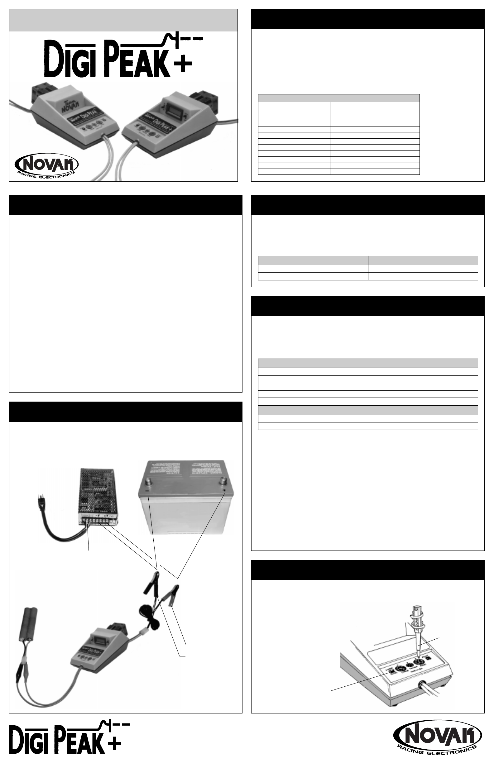
STEP 1 CONNECT INPUT
• Connect the input alligator clips on the back of
the charger to a 10 to 18 volt DC power source.
Power Supply
CAUTION: Do not connect
to AC power side.
STEP 2 CONNECT OUTPUT
• Connect the output alligator clips on
the front of the charger to a 4 to 8 cell
nickel-cadmium battery pack.
(1.2 volts DC/cell)
Car Battery
Red = Positive
STEP 3 SELECT THE CHARGING MODE
Determine the proper charging mode from table above. Slide the LINEAR / PULSE
mode select switch to either LINEAR or PULSE. Refer to illustration in Step 4
The charger runs hotter in the more common LINEAR charging mode and may require the
optional Novak Cooling Fan Kit #5635 if overheating occurs. The PULSE mode will allow
higher charging rates and cooler operating temperature, which can be used if the charger
overheats in the LINEAR mode. Please note that charging rates higher than 5 amps may
decrease the number of useful cycles in the life of the battery pack.
TRICKLE CHARGING
Trickle charging is only available in the LINEAR mode and can be used to slow charge the
battery or equalize the cells in the battery pack. When the battery pack is connected and
the charger is in the LINEAR mode, it will automatically begin trickle charging until the
START button is pressed. When the battery pack peaks in the LINEAR mode, the charger
will again automatically trickle charge the pack. If the TRICKLE dial is set to zero, no trickle
charging will take place either before or after the charge cycle.
ADJUSTING THE CHARGE RATE
STEP 4 ADJUST THE CHARGING RATE
Determine the proper charging rate from table above.
Rotate the current adjustment dial that corresponds to
the charging mode used. Refer to illustration below
Use the enclosed screwdriver
or a small flat blade screwdriver
to make this adjustment.
Current dials are ±10% accurate
Minimum
Maximum
Charge Rate
Adjustment
Black = Negative
LINEAR / PULSE Mode
Selection Switch
NOVAK ELECTRONICS, INC.
18910 Teller Avenue
Irvine, CA 92612
Page 2

DETAILED INFORMATION
DIGI-PEAK OPERATION
TO START CHARGING
1. Connect charger as shown in STEP 1 and STEP 2 on
front of instructions.
2. Adjust charging current as described in STEP 4 on
front of instructions.
3. Press and hold the START button until LED is lit.
Once the DIGI-PEAK charger starts charging, there is a
100 second lock-out time, during which the charger will
ignore voltage peaks and will not shut off. Be careful how
many times you repeak the battery pack, as the battery pack
voltage will continue to drop during the lock-out and may
damage the battery pack. After the lock-out time, the
DIGI-PEAK's peak detection circuitry is active. When the
battery voltage peaks and begins to drop, the charger
will shut off and the LED will go out (or flash, if trickle rate
is set above zero in the LINEAR mode). At this time, the
batteries will be warm to the touch, and are fully charged
and ready to run.
TO STOP CHARGING Disconnect the battery pack from
the output alligator clips. Remember that the 100 second
lock-out time is reset to zero whenever the charger is started.
PACK VOLTAGE
If you are using the DIGI-PEAK PLUS version charger,
turn on the LCD display and select VOLTS on the meter
slide switch to monitor the battery pack voltage. During
the charge cycle, the LCD meter will display the voltage
of the battery pack. If the charger is not connected to a
power source and is connected to a battery pack, the
LCD will display the battery pack voltage. If you are in the
LINEAR mode with the charger connected to an input
power source and no battery pack connected, the LCD
will display the approximate input voltage.
If you have the DIGI-PEAK version without the built-in
LCD display, you can connect an external voltmeter to
the charger to monitor the battery pack voltage during
the charge cycle.
MONITOR BATTERY PACK VOLTAGE
1. Set the voltmeter to the 20 volt DC range.
2. Insert the RED (Positive) voltmeter probe into the red
(+) output jack located on the back of the charger,
and insert the BLACK (Negative) probe into the black
(-) output jack also located on the back of the charger .
Refer to illustration below
3. The battery pack voltage is equal to that displayed on
the voltmeter.
USING A VOLTMETER
Red (Positive) Voltmeter
Probe to Red (+) Output Jack
BATTERY TIPS
GETTING THE MOST OUT OF YOUR BATTERIES
Getting the most run time and the longest life from your
batteries requires more than just charging at the correct
current. Proper care is a must for your battery packs.
REPEAK FOR MAXIMUM CAPACITY
When the battery pack voltage peaks at the end of the
charge and begins to drop, one or more cells are fully
charged and start to 'self discharge'. The excess energy
that is put into the cell after it has peaked results in the
dissipation of heat. You may notice when the battery
pack peaks, some of the cells get warmer than others.
This is because charge times differ slightly from cell to cell.
A good way to reduce the problem of some cells having
a more complete charge then others, is to repeak the
battery pack after about 30 minutes. This allows the cells
that have over-charged to discharge down to the level of
the remaining cells in the pack. Repeaking after the cells
have equalized with each other brings all the cells in the
pack up together for maximum capacity. It is best to time
this process so that you are able to run immediately after
repeaking, this will minimize the 'self-discharging' of the
batteries.
DISCHARGE FOR EXTENDED RUN TIME AND LONG LIFE
When you are done for the day, you should discharge
your battery packs to prepare them for the next time you
will use them. Storing and recharging a partially charged
battery pack will result in decreased performance from
your batteries, and will reduce the number of effective
charge cycles you will get from your batteries.
The simplest method to discharge your batteries is to put
a 30 ohm/10 watt resistor across the battery terminals as
shown below. As the pack discharges, some of the cells
will become reversed (the cell voltage becomes negative)
and will charge backwards. Charging a cell backwards at
high rates will damage the cell. However, the current
drawn through a 30 ohm resistor is low enough for the
cell to tolerate without damage. Connect the resistor to
the battery until the resistor cools to room temperature.
This may take several hours. Remove the resistor from the
battery pack at this time. Damage to the battery pack can
also occur if the resistor remains attached to the pack for
a time period longer than 24 hours.
Discharging Battery Pack
30Ω / 10W
Resistor
• Always discharge your battery packs after using them to
get the maximum performance and longest battery life.
TROUBLE-SHOOTING GUIDE
This section describes typical charger problems, causes,
and solutions. If you are unable to solve the problem, call
our Customer Service Department for assistance.
Charger Stops Before Battery Pack Is Fully Charged
• Input power supply is unstable. Connect the charger
input to a 12 volt DC automobile battery to check.
• The battery pack has one or more bad cells in it. Try
charging different battery packs. Monitor battery pack
voltage while charging. If voltage starts to drop before
the charger shuts off, charger is operating normally.
• Charging current is too high. If charge current is too
high for the battery pack, it will heat up prematurely
and cause the voltage to drop, shutting off the charger.
Reduce the charge current.
• Try charging using the LINEAR mode. Some battery
packs will not accept PULSE charging at higher charge
rates and will peak before the battery is fully charged.
• The charging current was lowered while charging after
the lockout time expired. Press the START button to
restart the charge cycle.
• Poor connection to the input power source or battery
pack. Check, clean, and tighten all connections.
• Charger has over-heated and has thermally shut down.
(See Below)
Charger Stops And Will Not Restart
Thermal Shut-Down has occurred–Try Novak Cooling Fan Kit #5635
• Cooling fan (if equipped) is not running. Fan should
run whenever the heat sink temperature rises above
115°F. Make sure fan is not plugged in backwards.
• Charger input voltage too high or charge current set
too high. Reduce input voltage to 1.5 volts DC above
the peak-voltage of the battery pack being charged or
reduce charge current. This more commonly happens
when charging 4 cell packs at too high of a current.
Charger Will Not Start
• Charger has thermally shut down and is cooling off.
Charger can be restarted after a few minutes when the
proper operating temperature has been reached.
• Bad connection in charging circuit. Check input/output
connections. Try charging a different battery pack.
Charger Stays On But Battery Pack Does Not Charge
• Input voltage too low. Input voltage to the charger
should be at 1.5 volts DC above the peak-voltage of the
battery pack being charged.
• Charge current set too low. Increase current.
Charge Current Will Not Adjust Properly
• Input voltage too low. The input voltage to the charger
should be 1.5 volts DC above the peak-voltage of the
battery pack being charged.
Charger Appears To Be Trickling
• The charge indicator LED will flash whenever the
charge current is below approximately 0.30 amp. The
charger is operating normally.
Charger Starts When First Connected To Battery Pack
• The 100 second lockout period of the charger is active.
Repress the START button to ensure proper startup.
Black (Negative) Voltmeter
Probe to Black (-) Output Jack
COOLING FAN
If you have purchased DIGI-PEAK or DIGI-PEAK PLUS
chargers without the factory installed cooling fan, follow
these steps to install the Novak Cooling Fan Kit #5635.
INSTALLING THE COOLING FAN
The Novak Cooling Fan is factory wired with a connector
to plug directly into the DIGI-PEAK and DIGI-PEAK PLUS
chargers, and includes two self-tapping screws to mount
into existing holes in the back plate of the charger.
1. Locate the air flow & rotation direction arrows that are
molded into the plastic housing of the cooling fan.
2. Mount fan with the air flow direction arrow pointing
towards the back plate of charger .
3. Make sure the plug on the cooling fan wiring will
reach the receptacle sockets on the lower left of the
charger back plate. If needed, rotate the cooling fan.
4. Insert screw into upper left and lower right holes on
cooling fan and through the openings of the heat sink
into the pre-drilled holes in back plate. Screw into
back plate with a screwdriver until screw heads just
touch the fan housing. Overtightening the fan screws
will warp and damage the back plate.
5. Insert plug from the cooling fan into the receptacle
sockets on lower left of the back plate. The red wire
should be closest to the heat sink for proper polarity.
Fan will not run if plugged in backwards.
Air Flow Direction Arrow
Cooling fan runs
only if heatsink
exceeds 115°F
Fan Receptacle Sockets
Refer to illustration below
(-)(+)
PRODUCT WARRANTY
Novak Electronics, Inc. guarantees the DIGI-PEAK and
DIGI-PEAK PLUS chargers to be free from defects in materials or workmanship for a period of 90 days from the
original date of purchase (verified by dated, itemized
sales receipt). This warranty does not cover components
worn by use, damage due to charging more than 8 or
less than 4 cells, damage to battery packs resulting from
improper connection or charging of a receiver battery
pack, any splices to the input or output wires, components damaged from excessive force when pressing the
START button or over-rotating the current adjust dials,
disassembling the case, tampering with the internal electronics, allowing water, moisture, or any other foreign
material to enter charger or get onto the PC board, or
allowing and exposed wire to short-circuit.
In no case shall our liability exceed the product's original
cost. We reserve the right to modify the provisions stated
in this warranty without notice.
Because Novak Electronics, Inc. has no control over the
connection and use of the charger, no liability may be
assumed nor will liability be accepted for damaged resulting from the use of this product. Every charger is thoroughly tested before leaving our facility and is, therefore,
considered operational. By the act of connecting or operating this charger, the user accepts all resulting liability.
CUSTOMER SERVICE
CUSTOMER SERVICE HOURS (PST)
Monday-Thursday: 8 a.m. - 5 p.m.
Friday: 8 a.m. - 4 p.m. (Closed every other Friday)
(949) 833-8873 • FAX (949) 833-1631
©1999 Novak Electronics, Inc. • All Rights Reserved
No part of these operating instructions may be reproduced without the written
permission of Novak Electronics, Inc.
All Novak chargers are designed and manufactured in the U.S.A.
DIGI-PEAK and DIGI-PEAK PLUS Digital Peak Detection Charger, and Digital
Peak Detection Circuitry are trademarks of Novak Electronics, Inc.
Printed in the U.S.A. (8/99) #IM-4400-4
SERVICE PROCEDURES
Before sending in your DIGI-PEAK or DIGI-PEAK PLUS
charger for service, review the Trouble-Shooting guide
and the instructions. The charger may appear to have
failed when other problems exist.
PLEASE NOTE: DIGI-PEAK & DIGI-PEAK PLUS chargers
that operate normally when received will be charged
a minimum service fee and return shipping costs.
WHAT TO SEND: Fill out all of the information requested
on the enclosed CHARGER SERVICE CARD and return it
with your charger.
WARRANTY WORK: For warranty work, customer MUST
CLAIM WARRANTY on the CHARGER SERVICE CARD and
include a valid cash register receipt with purchase date
on it, or an invoice from previous service work for the
charger. If any warranty provisions have been voided
there will be a service charge.
SERVICE COSTS: Customer is responsible for all service
costs (Parts, labor, and shipping/handling charges).
Chargers returned UPS/COD CASH ONLY. See CHARGER
SERVICE CARD for other payment and shipping options.
ADDITIONAL NOTES:
• Hobby dealers/distributors are not authorized to replace chargers thought to be defective.
• If a hobby dealer sends your charger in for service, be
sure to submit a completed CHARGER SERVICE CARD
to the dealer and make sure it is sent with the charger.
• To provide the most efficient service possible to our
customers, it is not out policy to contact customers by
phone or mail.
• Novak Electronics does not make any electronic components (transistors, resistors, fans, etc.) available for sale.
SEND CHARGERS TO:
NOVAK ELECTRONICS, INC.
18910 Teller Avenue
Irvine, CA 92612
NOVAK ELECTRONICS, INC.
18910 Teller Avenue
Irvine, CA 92612
 Loading...