

Page 1
THE DIG UNIT SET-UP GUIDE
#55-5450-1 7-2009
SPECIFICATIONS
Input Voltage .................................................................4-12 V
Power Consumption ......................................................
Output Current (handling) ........................................... 5 Amps
Weight
#5450
....................................................0.12 oz. / 3.50 grams
Size .................1.53” x 0.65” x 0.49” / 39.0 x 16.5 x 12.5 mm
LEDs
...................................................... 2 on-board, 2 external
This one-of-a-kind unit requires two brushless or brushed systems and a three-channel transmitter to
operate. Refer to the Novak Web site (www.teamnovak.com) for a list of compatible systems and transmitters.
To benefit from all of the technical features of The Dig,
PLEASE READ ALL INSTRUCTIONS BEFORE OPERATION
HARNESS INSTRUCTIONS
Refer to Figure 1 for the following steps.
1. Using one signal harness, connect the AUX
output (usually CH. 3 or CH. 4) of the
receiver to the AUX input (Fig. 1, #1) of the
Dig Unit.
2.
Using the other signal harness, connect the
Throttle output (CH. 2) of the receiver to the
Throttle input (Fig. 1, #2) of the Dig Unit.
3. Connect the signal harness from the rear
ESC to the rear output (Fig. 1, #3) of the
Dig Unit.
It is recommended to disconnect the red wire
TRANSMITTER ADJUSTMENTS
1. Locate the AUX channel on the transmitter.
A three-position switch or dial control is required to
operate the Dig Unit. A two-position switch will not work.
2. With some transmitters, the AUX channel must
be adjusted. If your transmitter offers AUX
adjustments, the following is recommended:
a) Set HIGH ATV or EPA settings to the
maximum setting.
b) Set LOW ATV or EPA settings to the
maximum setting.
c) Make sure the AUX trim setting is set to
zero or the middle setting.
from one of the ESC signal harnesses and use the
switches for both the front and rear ESCs.
4. Connect the signal harness from the front
ESC to the front output (Fig. 2, #4) of the
Dig Unit.
5. Connect the LED harnesses to the LED
indicator plugs (Fig. 1, #5 & #6) of the
Dig Unit. Referring to Figure 1, the blue
LED corresponds to #5 and the red LED
corresponds to #6.
MOUNTING THE DIG
1. Use double-sided tape or tie-wraps to
secure the Dig Unit to a safe location near
the vehicle’s receiver, making sure that the
One-Touch Set-Up button is easily accessible.
2. Use tie-wraps to secure the blue and red
indicator LEDs to an easily visible location in
the vehicle.
3. Double check that the Dig Unit is located in
a place that will not pinch or damage the
wires or harnesses.
ONE-TOUCH PROGRAMMING
Before programming Novak’s One-Touch Setup
for the Dig Unit, both front and rear ESCs need to
be set up either simultaneously or individually. Be
sure to follow manufacturer’s set-up procedures
for the ESCs carefully.
1. Turn on the transmitter’s power.
2. Before turning on your vehicle’s electronics,
make sure that your transmitter’s throttle
position and the AUX switch or dial are both in
the NEUTRAL position.
3. PRESS and HOLD the Dig Unit’s One-Touch button.
4. Turn on the power to the ESC.
5. CONTINUE TO HOLD the Dig’s One-Touch
button UNTIL THE RED LED TURNS ON,
releasing the button AS SOON AS THE
LED TURNS RED.
6. Move the AUX switch or dial to one end
position, and hold it there until the green
status LED TURNS SOLID GREEN.
7. Move the AUX switch or dial to the
opposite end position, and hold it there
until the green status LED BLINKS GREEN.
When the green light stops blinking, the Dig
Unit is programmed.
8. Return the AUX switch or dial to NEUTRAL.
10 mA
PROPER FUNCTION
Please follow the steps below to ensure that your Dig
Unit is adjusted properly.
1.
Turn on the transmitter and both speed controls power.
2. When the AUX switch is in the neutral position,
the blue and red indicator LEDs should be
illuminated, as well as the red LED and green LED
on board the Dig Unit.
a) Apply a small amount of throttle to confirm
that both front and rear speed controls are
functioning properly.
3. Position the AUX switch to the left or the right to
illuminate the red front indicator LED (Fig.1, #6).
This position should also illuminate the red LED
on board the Dig Unit. These should be the only
lights illuminated on the Dig Unit.
a) Apply a small amount of throttle to confirm
that ONLY the front ESC is operating.
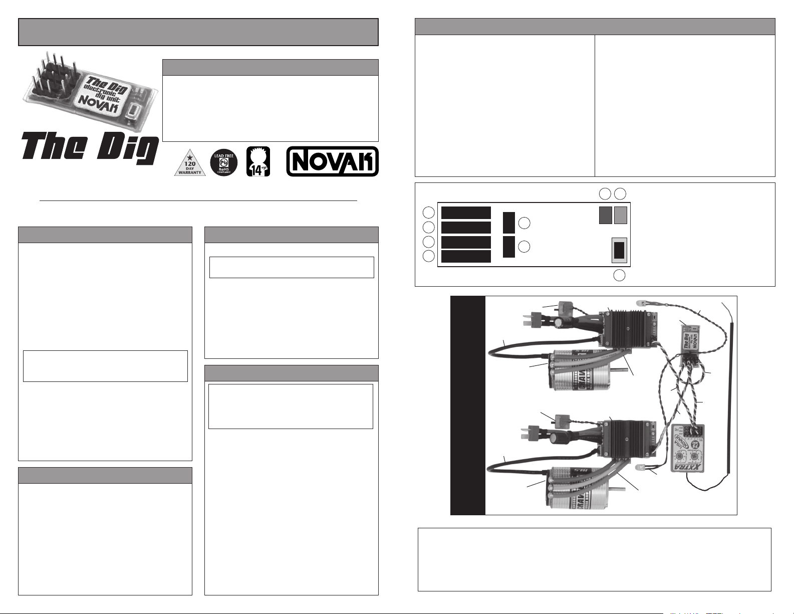
FIGURE 1
1
2
3
4
– + S
– + S
– + S
– + S
–
5
+
+
6
–
ESC ON/OFF
switch
sensor
harness
front Crawler
sensor-based
brushless motor
ESC ON/OFF
switch
(FIGURE 2)
sensor
harness
THE DIG SETUP PHOTO
rear Crawler
sensor-based
brushless motor
PRODUCT WARRANTY: The Dig Unit is guaranteed to be free from defects in materials or workmanship for a period of 120 days from the original date of
purchase (verified by dated, itemized sales receipt). Warranty does not cover incorrect installation, components worn by use, tampering with internal electronics, allowing
water, moisture or any other foreign material to enter module or get onto the PC board, or any damage caused by a crash, flooding or natural disaster.
Because Novak has no control over the connection & use of the module, no liability may be assumed nor will be accepted for any damage resulting from the use of this
product. Every Novak module is thoroughly tested before leaving our facility and is, therefore, considered operational. By the act of connecting/operating module, user
accepts all resulting liability. In no case shall our liability exceed the product’s original cost. We reserve the right to modify warranty provisions without notice. Designed
by Novak Electronics, Inc. in Irvine, Calif., and assembled with globally sourced components.
©2009 Novak Electronics, Inc. • All Rights Reserved • No part of these instructions may be reproduced without the written permission of Novak Electronics, Inc. • The
Dig: Electronic Dig Unit for Dual System Crawlers is a trademark of Novak Electronics, Inc.
b) Under normal operation, this is the “Front
Dig” function. This will allow the front motor
to spin (dig), while the rear motor locks into
neutral position (hill brake).
4. Position the AUX switch to the opposite direction
than the previous step. The blue rear indicator
LED (Fig. 1, #5) should be illuminated, as well
as the green LED on board the Dig Unit. These
should be the only lights illuminated on the
Dig Unit.
a) Apply a small amount of throttle to confirm
that ONLY the rear ESC is operating.
b) Under normal operation, this is the “Rear Dig”
function. This will allow the rear motor to spin
(dig), while the front motor locks into neutral
position (hill brake).
7 8
front ESC
rear ESC
1. AUX (CH. 3 or CH. 4) input from receiver
2. Throttle (CH. 2) input from receiver
3. Output to rear ESC
4. Output to front ESC
5. LED harness indicator (blue) for rear ESC
6. LED harness indicator (red) for front ESC
7. On-board (red) LED indicator for front
ESC (also used with One-Touch Set-Up)
8. On-board (green) LED indicator for rear
9
blue, yellow &
orange motor
phase wires
*refer to Figure 1 for input harness installation
ESC (also used with One-Touch Set-Up
9. One-Touch Set-Up button
red LED
The Dig
blue LED
harness
blue, yellow &
orange motor
phase wires
harness
Unit
1*
2*
3*
4*
 Loading...