

North Star PA101, PA071, PA131, PA191, PA321 User Manual
...
P/N: 7243683
(Rev. A1 5/24/10)
If you have questions when i n stalling, programming, operating or maintaining this system
CALL TOLL FREE in Canada call
1---800 --- 627 ---3497 1---800 --- 752 ---3273
1

SHIPMENT INSPECTION
Thoroughly check the commercial system for possible shipping damage and/or parts loss. Also inspect and
note any damage to shipping cartons, crating, etc. If damage is present, notify the transportation company.
The manufacturer is not responsible for damage or parts loss in shippment.
Note: Do not mistakenly discard small parts bags when unpacking the system.
All models are shipped in 3 cartons; (1) resin tank, (2) brine tank, and (3) controller. The mineral bed
consists of 1 cubic foot bags of water softening resin, and 17 or 50 pound bags of various grades of
gravel. Refer to the following chart.
MODEL ''
1CU.FT.BAGSOFRESIN 2 3 4 6 8 10
BAGS OF
GRAVEL
(LBS)
fine 1 (17) 2 (17) 2 (17) 1 (50) 1 (50) 1 (50)
medium 1 (50) 1 (50) 1 (50)
coarse 1 (50) 1 (50) 1 (50)
PA071 PA101 PA131 PA191 PA251 PA321
TABLE OF CONTENTS
Page No.
Specifications .......................................................................................... 4--5
Dimensions ............................................................................................ 6
Resin Loading and Assembly ............................................................................ 7-- 8
Planning Installation
InstallationSteps...................................................................................... 8-- 9
Inlet--OutletPlumbingDrawing ......................................................................... 9
NotesandCautions ................................................................................... 10
Connecting Brine Tank ................................................................................. 10
Connect Valve Drain Hose ............................................................................. 11
PressureTesting ...................................................................................... 12
Filling Brine Tank with Water and Salt .................................................................... 12
ProgrammingtheController ............................................................................ 12--15
Sanitizing Procedures ................................................................................ 14--15
Water Softener Controller Setup Information ............................................................. 16
ResettingTime...................................................................................... 17
ControllerFeaturesandOptions ....................................................................... 17--20
FCCInformation..................................................................................... 19
Operation
DemandControllerandWaterMeter ..................................................................... 20
Water Flow Through the Conditioner ..................................................................... 21-- 23
Service Information
Salt, Recommended Type and Refilling .................................................................. 23
Removing a Salt ‘‘Bridge’’ .............................................................................. 23
Cleaning the Nozzle / Venturi ........................................................................... 24
Controller
WiringSchematic ..................................................................................... 25
ErrorCodeTable...................................................................................... 26
Troubleshooting ...................................................................................... 25--28
Repair Parts
BrineTanksandBrineValves ........................................................................... 29--31
ResinTanks/Distributor/Controller ..................................................................... 32--33
ValveAssembly....................................................................................... 34--35
2

SAFETY GUIDES
Follow the installation instructions carefully. Failure to install the commercial system properly voids the
warranty.
Before you begin installation, read this entire manual. Then, obtain all the materials and tools you will need
to make the installation.
Check local plumbing and electrical codes. The installation must conform to them.
Use only lead--free solder and flux for all sweat--solder connections, as required by state and federal codes.
Do not locate this system where freezing temperatures occur. Do not attempt to treat water over 120F. Freez-
ing, or hot water damage voids the warranty.
Avoid installing in direct sunlight. Excessive sun heat may cause distortion or other damage to non--metal-
lic parts.
This system requires a minimum water pressure of 30 psi at the inlet. MAXIMUM ALLOWABLE Inlet water
pressure is 125 psi. If daytime pressure is over 80 psi, nighttime pressure may exceed the maximum. Use
a pressure reducing valve if necessary. (Adding a pressure reducing valve may reduce the flow.)
The system works on 24 volt--60 Hz electrical power only. Be sure to use the included transformer.
This system is not intended to be used for treating water that is microbiologically unsafe or of unknown quality
without adequate disinfection before or after the system.
SPECIFICATIONS
EQUIPMENT SPECIFICATIONS
SOFTENERS
MODEL
TANK SIZE (IN) 12” x 54” 17” x 58“ 17” x 58“ 24” x 71” 24” x 71” 24” x 71”
4 LBS. 37,000 54,000 72,000 108,000 144,000 180,000
CAPACITY (GRAINS) @
SALT USAGE PER CU.
FT. RESIN
RECOMMENDED FLOW
RATES ¡
RESIN (CU. FT.) 2 3 4 6 8 10
BAGS OF GRAVEL (LBS)
SALT CAPACITY 340# 1000# 1000# 1500# 1500# 1500#
PIPE SIZE (IN) 1” 1” 1” 1” 1” 1”
BACKWASH/FST. RNS. FLOW RATES 3.0 7.0 10.0
6 LBS. 50,000 72,000 96,000 144,000 192,000 240,000
8 LBS. 61,000 84,000 112,000 168,000 224,000 280,000
10 LBS. 67,000 93,000 124,000 186,000 248,000 310,000
12 LBS. 71,000 99,000 132,000 198,000 264,000 330,000
5GPM 2.9 nP 1.4 nP 1.5 nP 1.3 nP 1.3 nP 1.3 nP
10 GPM 7.3 nP 4.2 nP 4.4 nP 3.4 nP 3.6 nP 3.8 nP
15 GPM 13.0 nP 8.0 nP 8.6 nP 6.9 nP 7.3 nP 7.6 nP
20 GPM 20.0 nP 13.0 nP 14.0 nP 11.6 nP 12.0 nP 12.4 nP
25 GPM 28.6 nP 19.1 nP 20.5 nP 17.9 nP 18.4 nP 19.0 nP
30 GPM 38.3 nP 26.5 nP 28.3 nP 24.0 nP 24.9 nP 25.6 nP
35 GPM N/A 35.0 nP 37.0 nP 32.0 nP 33.0 nP 34.0 nP
40 GPM N/A N/A N/A 41.0 nP 42.2 nP 43.4 nP
FINE 1 (17#) 2 (17#) 2 (17#) 1 (50#) 1 (50#) 1 (50#)
MEDIUM 1 (50#) 1 (50#) 1 (50#)
COURSE 1 (50#) 1 (50#) 1 (50#)
PA071 PA101 PA131 PA191 PA251 PA321
¡ psi pressure loss @
continuous flow rates
intermittent or peak flow rates
flow rates not recommended (hardness leakage, reduced efficiency, etc.)
3

SPECIFICATIONS
PROGRAMMING INFORMATION
MODEL
RESIN QUANTITY (CU. FT.) © 2 3 4 6 8 10
REFILL RATE (GPM) 0.3 0.5 0.5 0.5 0.5 0.5
TURBINE SIZE (IN) 1” 1” 1” 1” 1” 1”
FILL FLOW PLUG LOCATION
BRINE CYCLE FLOW RATE (GPM) .33 .58 .57 1.1 1.1 1.1
BR. RNS. CYCLE FLOW RATE (GPM) .22 .48 .47 .89 .89 .89
BKW. CYCLE & FAST RINSE CYCLE
FLOW RATE (GPM)
BKW. FAST RINSE FLOW PLUG
IDENTIFICATION & LOCATION
FREEBOARD (INCHES) ¢ 19 30 22 36 27 18
LOW
FILL CYCLE TIME (MIN.)
HIGH
BRINING / BR. RINSE
CYCLE TIME (MIN.)
BRINE TIME (MIN) @
SALT DOSE (LBS)
BACKWASH TIME (MIN) 13 15 15 15 15 15
FAST RINSE TIME (MIN) 4 5 5 5 5 5
LOW SALT
HIGH SALT
LBS MINUTES
4, Auto Adj.
or Salt Eff.
6 137 110 150 145 150 175
8 140 105 145 135 145 170
10 135 100 135 130 135 160
12 129 95 130 125 130 150
PA071 PA101 PA131 PA191 PA251 PA321
See key no.
33, page 34
3 7 7 10 10 10
Black --
tan dot (.5)
4.7
31.0
142
112
141 115 160 150 160 180
Brown (.7) Orange (.10)
BEHIND DRAIN ELBOW OF 1” VALVE (SEE PAGE 34)
13.4
50.2
115
95
SOFTENERS
See key no. 16, page 31
17.9
67.0
160
130
16.1
60.3
150
125
21.4
80.4
160
130
26.8
100.5
180
150
© Synthetic high capacity resin
¢ Nominal distance from top of resin bed to top of the tank. This dimension can varyseveral inches, depending on resin moist ure content,
degree of bed expansion or packing, resin tank diameter tolerances, etc.
If you have questions when installing, programming, operating or maintaini ng this system
CALL TOLL FREE in Canada call
1---800 --- 627 ---3497 1---800 --- 752 ---3273
4

SPECIFICATIONS
EQUIPMENT SPECIFICATIONS
FILTERS
MODEL
TANK SIZE (IN) 12” x 54” 12” x 54” 17” x 58” 12” x 54” 17” x 58” 12” x 54”
CONTAMINANT REMOVAL
SERVICE WATER FLOW RATE (GPM) 4--8 4--8 8--16 4--8 8--16 4--8
2GPM 1.0 nP 1.0 nP 0.6 nP 1.0 nP
4GPM 2.3 nP 2.3 nP 1.1 nP 2.3 nP
6GPM 3.9 nP 3.9 nP 2.2 nP 3.9 nP
RECOMMENDED
FLOW RATES
(GPM @ PSI)
MINERAL (CU. FT.) 2 2 4 2
BAGS OF
MINERAL (LBS)
*Use only partial
bags of supplied
mineral
BKW/FR FLOW
RATES
PIPE SIZE (IN)
WATER PRESSURE LIMITS (PSI) 30 -- 125 30 -- 125 30 -- 125 30 -- 125
MAXIMUM WATER TEMPERATURE 35 -- 100 35 -- 100 35 -- 100 35 -- 100
ELECTRICAL RATING 24v 60Hz 24v 60Hz 24v 60Hz 24v 60Hz
8GPM 5.7 nP 5.7 nP 3.3 nP 5.7 nP
10 GPM 7.9 nP 7.9 nP 4.6 nP 7.9 nP
12 GPM N/A N/A 5.9 nP N/A
14 GPM N/A N/A 7.4 nP N/A
16 GPM N/A N/A 9.7 nP N/A
18 GPM N/A N/A 13.7 N/A
ANTHRACITE 2 (65#)* -- -- -- -- 2 (61#)*
FILTER SAND 1 (52#) -- -- -- -- --
GARNET 1 (33#)* -- -- -- -- 1 (33#)*
ACTIVATED
CARBON
MANGANESE
GREENSAND
GRAVEL 2 (17#) 2 (17#) 1 (50#) 1 (17#) 2 (34#) 1 (17#)
LOCATION Key #10, page 34
(GAL/MIN) 12 12 15 5 5 12
FA 1” 1” 1” 1” 1” 1”
FB 1--1/2” 1--1/2” 1--1/2” 1--1/2” 1--1/2” 1--1/2”
MULTI-MEDIA ALL PURPOSE CARBON GREENSAND
PA121 P A121 P A171 P A121 P A171 P A121
based on
water analysis
-- -- -- 2 (58#) 4 (116#) --
-- -- -- -- -- 2 (170#)
based on water analysis based on water analysis
maximum
iron 20 ppm
dependant on media
5
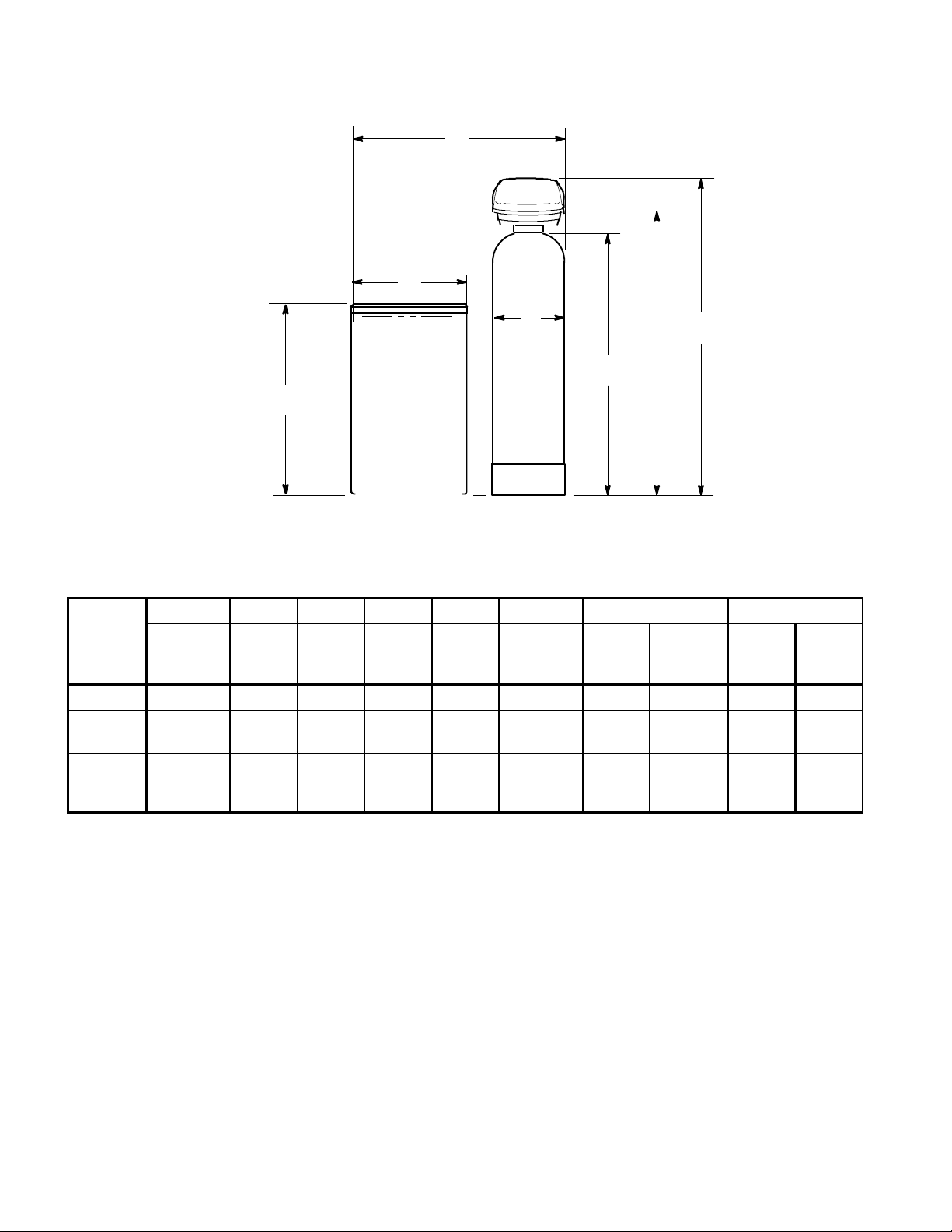
DIMENSIONS
minimum floor space required
G
F
A
B
E
ROUND
BRINE TANK
A B C D E F G INLET--OUTLET
MODEL
PA071 12.3” 55” 58” 63.75” 39” 17” 35.3” 70” 1” 3.8”
PA101
PA131
PA191
PA251
PA321
Resin
Ta n k
Diameter
17.6” 59.5” 62.5” 68.25” 50” 24” 48” 102” 1” 3.8”
24” 76” 79.8” 85.5” 51” 30” 60” 90” 1” 3.8”
Resin
Ta n k
Height
Inlet-Outlet
Height
Overall
Height
Brine
Ta n k
Height
Brine
Ta n k
Diameter
Single
D
C
Multiple¡Pipe
Size ©
Pipe
Center
lines
¡ Includes 6” between tanks.
© Sweat copper (1”) fittings supplied. Optional 1–1/2” fittings available, part no. 7129211, package of 2.
6
RESIN LOADING AND ASSEMBLY
1. Move the resin tank into installation location (see
page 8). Set it on a flat, level surface. If a twin installation, keep tanks separated for ease of service.
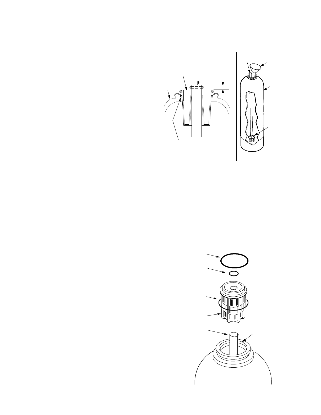
2. Remove the shipping cap, top distributor and o--rings. On all models,placethebottom distributor into
the resin tank. Check the distributor length as shown
in Figure 1 and adjust if needed. Center the distributor
in the tank.
3. With a pail or hose, fill the tank with 1 to 2 feet of
water. The water acts as a cushion to protect the bottom distributor while filling the tank with gravel and
resin.
4. Plug the end of the distributor tube with a clean
rag, to keep gravel and resin out.
5. Using a larger neck funnel, add the specified (see
pages 2 and 4) amount of gravel. Be sure the dis-
tributor remains centered.
Note: When coarse, mediumand finegravels are spe-
cified, add in that order.
6. Add the specified amount of resin, using water
sparingly to speed flow through the funnel.
7. Flush the tank opening with water to clean resin
beads from the top of the tank. Then, remove the rag
from the distributor tube.
8. Finish filling the tank withwater, up to the top of the
tank.
Important: Be sure to fill with water. This will eliminate air space and prevent excessive air ---head pressure when the water conditioner is pressurized.
9. Install the o ---ring seals and top distributor exactly
as shown in Figure 2. If the o--- rings need lubrication,
use a high quality silicone grease.
continued
Figure 1
clean
rag
top edge of
top distributor
resin
tank
distributor tube
0” to 1/2”
P l a c e t h e 2 --- 3/ 4 ” x 3” o --ring under the top distributorandslidetopdistributor assembly over distributor tube.
Note: Resin tank height can vary somewhat
within manufacturing tolerance. So the bot-
tom distributor riser pipe has proper clearance with inside valve porting, check for
the correct length as shown above. Cut the
riser if needed to adjust the length. Be sure to
remove burrs and sharp edges.
Figure 2
o --- r i n g s e a l
2---7/8” x 3- --1/4”
o---ring seal
13/16” x 1---1/16”
o---ring seal
2---3/4” x 3”
top distributor
bottom distributor
Be sure o---ring
sealing surfaces
are clean.
funnel
resin tank
bottom
distributor
(centered)
7
RESIN LOADING AND ASSEMBLY
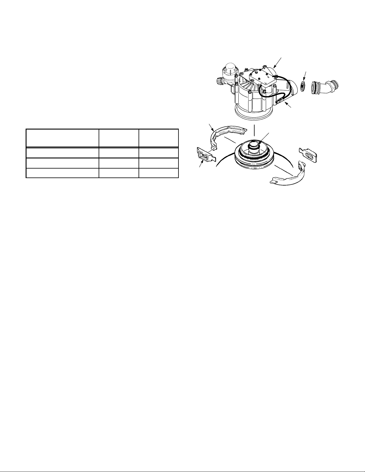
10. Lower the valve assembly onto the resin tank,
centering over the bottom distributor tube. Push
downward, against the o---ring, and install the clamp
sections, securing with the retainers.
Important: Check the valve outlet to be sure the turbine and turbine support are securely in place.
11. Verify that the proper backwash flow washer is
installed. If not, replace with correct flow washer from
parts bag.
Model
BW Flow
Washer
ID Mark
PA071 3gpm tan dot
PA 101 & PA131 7gpm brown
PA 191, P A251 & PA321 10 gpm orange
clamp
section (2)
clamp
retainer (2)
valve
outlet
Valve Assembly
bottom
distributor tube
Figure 3
BW flow
waxher
PLANS FOR LOCATION AND INSTALLATION OF SYSTEM
WATER SUPPLY: The system requires a potable water supply that will provide a continuous flow to meet regeneration flow specifications. A minimum pressure of 30 psi is required at the conditioner inlet.
‘‘FULL LINE’’ (both hot and cold water) WATER CONDITIONING: Connect the system, to the water supply
pipe, immediately after (downstream) the municipal supply water meter or well supply pressure tank.
CONDITIONING HOT WATER ONLY: Connect the system, to the water supply pipe, before (upstream) the
water heater.
CAUTIONS: (1) Do not install the conditioner after,ordownstreamfromthe water heater. Hot water will
damage inner parts of the system, and may cause the loss of the water softening resin bed. (2) To reduce
the risk of hot water flowing backwards, into the conditioner, piping between the conditioner and water heater should be as long as possible.
DRAIN: A drain is needed nearby the conditioner, capable of carrying away backwash water at the rate of flow
listed in the specifications. A floor drain is preferred. Other approved drain points are acceptable, if they do
not cause a back---pressure on the conditioner drain hose or pipe.
ELECTRICAL: The system works on 24 volts only. A transformer is included to reduce 120V--- 60Hz electrical
power. An approved, grounded outlet is needed within 10’ of the conditioner controller for the transformer. The
conditioner includes a 10’ power cable to connect between the transformer and the controller. The controller
may be mounted in any convenient location. You may either fasten to a wall using the mounting holes molded
in the controller case, or wrap a chain around the tank and connected to the mounting holes on controller case.
SPACE REQUIREMENTS: Be sure to allow sufficient area around the resin and brine tanks for refilling with
salt and other service. Minimum floor space and other dimensions are shown on page 6.
8
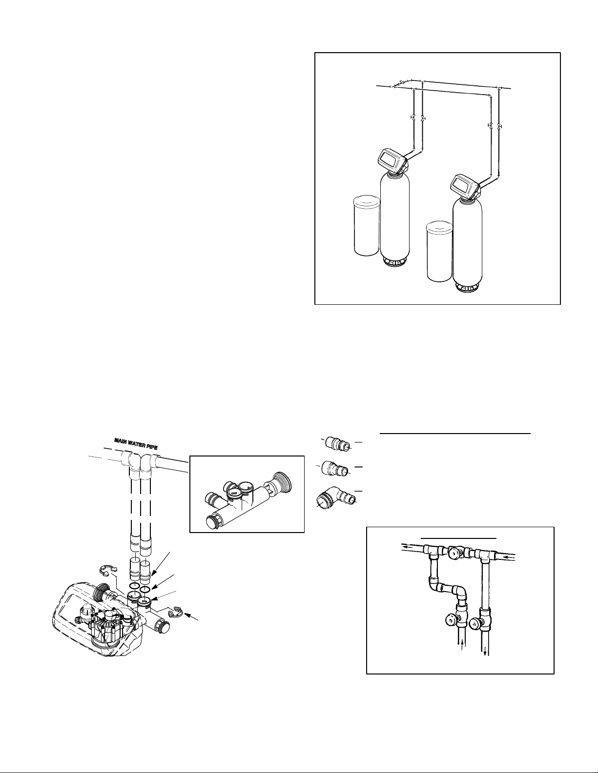
MATERIALS YOU MAY NEED
Use the drawing at the right as a guide for your installation. The drawing shows typical connection using
fittings included with the system, and with optional
SOFT
WATER
Figure 4
HARD
WATER
items available.
J Be sure to install a 3 --- valve bypass system, or use
the optional bypass valve, #7195408.Bypass
valves allow you to turn off water to the system, for
servicing, while having full--- line bypass to the establishment.
J A 5/8” minimum inside diameter hose or pipe is re-
quired for the valve drain (see page 11). The drain fitting has standard garden hose threads, and hose
barbs. Adaptors are available from most hardware
stores to convert the fitting to accept rigid pipe. A garden hose is also needed for the drain on brine tanks.
J For in and out pipes to the conditioner, use copper,
CPVC plastic or threaded pipe and fittings. Avoid joining copper and galvanized together as corrosion will
occur rapidly. Included inlet and outlet adaptors are
1” male copper. Optional fittings available are shown in Figure 5.
J Multiple Tank Installations: To promote equal water flow, inlet and outlet plumbing configuration to each
valve should be as identical as possible. Use the same fittings and pipe lengths for each connection.
TYPICAL INLET-- OUTLET PLUMBING CONNECTIONS
Figure 5
SOFT
WATER
*included with conditioner
HARD
WATER
BYPASS VALVE #7195408
1” copper tube (2) *
o--ring seal (2) *
Bypass Valve
clip (4) *
OPTIONAL INLET/OUTLET FITTINGS
#7104546 CPVC Nipple --- Use in place of
included copper inlet and outlet tubes.
#7129211 Adaptor Fitting, 1–1/2” (2) -- - Use in
place of included copper inlet and outlet tubes.
#7120259 Elbow --- Extends inlet and/or outlet in
any 90° direction.
SOFT
WATER
3 --- V A LV E BY P A S S
outlet valve
bypass
valve
FROM
outlet
HARD
WATER
inlet valve
TO inlet
9
INSTALLATION STEPS
PIPING ASSEMBLY NOTES AND CAUTIONS:
S BE SURE to close the main water supply valve before beginning.
S BE SURE to plumb so hard water flows to the valve inlet fitting.
S CAUTION: When soldering, make sub--- assemblies as needed to prevent soldering heat damage to the
conditioner valve or bypass valve. Be sure soldered piping has cooled before connecting to the conditioner.
S UseTeflontapeorpipejointcompoundonexternalpipethreads.
S Lubricate o---ring seals with high quality silicone grease.
1. Looking at the illustrations on page 9, and observing the notes above, run piping from the main water sup-
ply pipe to the valve inlet. Then, run return piping from the valve outlet to the supply pipe. Be sure to include
a3---valvebypass,oruseoneoftheoptionalbypassvalves.
Note: When working with soldered copper, be sure to observe the caution above to avoid damage to non ---me-
tallic parts.
Important: Support in and out piping in an acceptable manner, to prevent weight stress on the conditioner
valve.
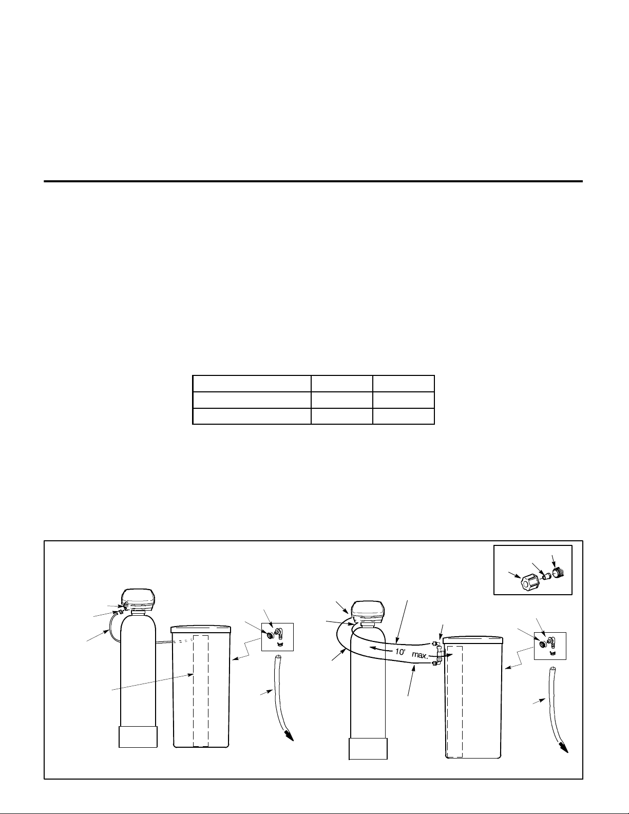
2. Move the brine tank assembly into position nearby the resin tank. Enough tubing is included to allow locating
the tank up to 10 ’ away from the resin tank (Figure 6).
3a. Connect Tubing --- Model PA071: Thread the brine tube through the hole of the brine tank sidewall. Fasten
tubing to the nozzle assembly (Figure 6) using the compression nut--- ferrule, tightening securely, by hand only.
3b. Connect Tubing --- All other models: Verify that the proper nozzle & venturi are installed in nozzle assembly.
If not, replace with correct pair.
Model Venturi Nozzle
PA101, PA131 Almond White
PA191, PA251 & PA321 Gray Gray
¡ Install two elbows (in separate parts bag with the brine tank) into the top and botto m of the nozzle assembly (Figure 6).
© Using tubing inserts and compression nuts, fasten lengths of tubing to the two elbows.
¢ Connect tubing from the bottom of thenozzle assembly, to thetop adaptor on thefront of thecondition-
er valve assembly. Use a tubing insert and compression nut (tighten securely) as shown in the inset drawing.
£ Do the same to connect tubing from the top of the nozzle, to the bottom check valve fitting on the front
of the conditioner valve assembly.
continued
insert
adaptor
drain
hose
fitting
hose
nozzle/venturi
nut--ferrule
brine
valve tubing
brinewell
grommet
overflow
hose
adaptor
drain
hose
Figure 6
adaptor
check
valve
pressure
brine return
nozzle
assembly
elbow (2)
nut
grommet
overflow
BRINE TANK
to floor
drain
10
BRINE TANK
to floor
drain
INSTALLATION STEPS
4. Push theelbow fitting, with garden hose threads on
one end, into the grommet in the sidewall of a round
brine tank. Attach a length of drain hose to the fitting
as follows.
Attachalengthof5/8”I.D.gardenhosetotheelbow
and run to the floor drain.
Important: This gravity drain is a safeguard to carry
away excess water if the brine tank should overfill.
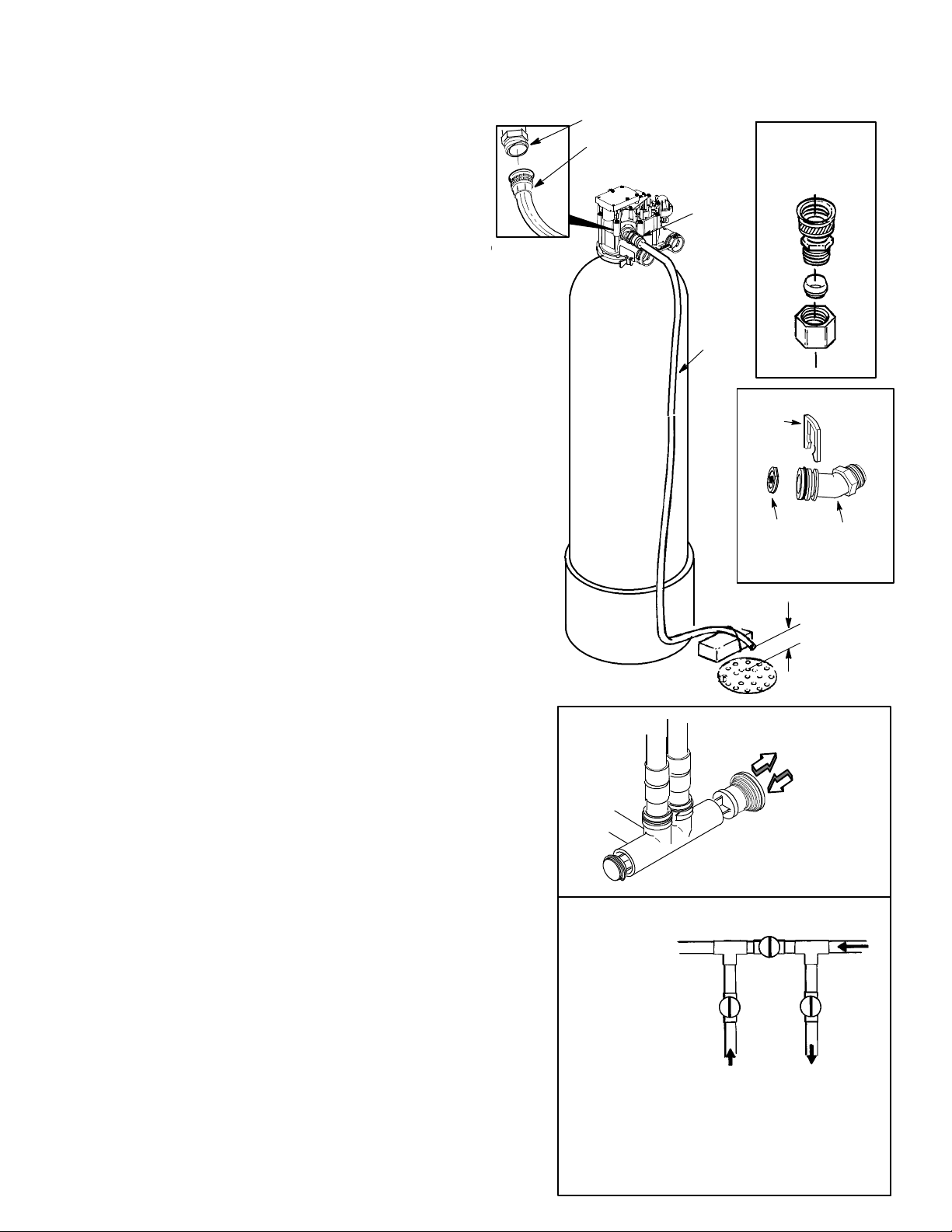
5. Install Valve Drain Hose: The drain fitting accepts
a 5/8” I.D. minimum drain hose, either garden hose
connection, or hose onto a barb fitting (Figure 7). To
use the garden hose threads, cut the barbed section
of the elbow off with a hack---saw.
Attach the drain hose to the drain elbow. If using the
barbs, install an automotive type clamp to secure the
hose to the elbow. Place the other end of the hose at
the drain point, and observe the following.
S Fastenthehoseinplaceat the drain point. Pres-
surized water, exiting the hose during regenerations, could cause it to ‘‘whip’’.
S Provide an air ---gap of at least 1–1/2” between the
end of the hose and the floor drain cover . The air --gap prevents a possible back siphon if sewer water should backup.
S Forlongerorraiseddrainhoseruns,a3/4”dia.
hose (minimum) is recommended to reduce
b a c k --- pr e s s ur e . Ba c k --- p r e s s u r e ca n r e s t r i c t fl o w
through the nozzle/venturi, affecting brine draw.
S If codes require a rigid drain pipe, purchase a gar-
den hose thread by compression fitting, available
from most hardware stores.
drain fitting
valve drain
hose
single
Bypass
Valve
drain
elbow
valve
drain
hose
Figure 7
garden hose x
compression
adaptor (typical)
clip
flow
plug
drain
elbow
FLOOR
DRAIN
Figure 8
11
3 --- V a l v e B y p a s s
D for SERVICE:
--- O p e n the inlet and outlet valves.
--- C lo s e the bypass valve.
D for BYPAS S:
--- C lo s e the inlet and outlet valves.
--- O p e n the bypass valve.
outlet
valve
PULL OUT
for service
PUSH IN
for bypa ss
bypass
valve
inlet
valve
 Loading...