

North Star NSWHCW Installation Manual

Designed, Engineered &
Assembled in the U.S.A.
Model NSWHCW
How to install, operate
and maintain your Central
Water Filtration System
If you have any questions or concerns when
installing, operating or maintaining your central
water filtration system, call our toll free number:
1-800-972-0135
or visit www.northstarwater.com
When you call, please be prepared to provide
the model and serial number of your product,
located on the rating decal on back of the cover.
System tested and certified by NSF International
against NSF/ANSI Standard 42
for the reduction of chlorine taste and odor,
and certified to NSF/ANSI Standard 372.
System tested and certified by the Water Quality
Association against CSA B483.1.
Manufactured and warranted by
North Star Water Treatment Systems
1890 Woodlane Drive
Woodbury, MN 55125
Installation and Operation Manual
7360671 (Rev. F 3/8/19)

TABLE OF CONTENTS
Page
pecifications & Performance Claims . . . . . . . . . . . . . . . . . . . . . . . . . . . . . . . . . . . . . . . . . . . . . . . . . . . . . . . . . . . . 3
S
Central Water Filtration System Safety . . . . . . . . . . . . . . . . . . . . . . . . . . . . . . . . . . . . . . . . . . . . . . . . . . . . . . . . . . . 4
Before You Start . . . . . . . . . . . . . . . . . . . . . . . . . . . . . . . . . . . . . . . . . . . . . . . . . . . . . . . . . . . . . . . . . . . . . . . . . . . . 4
Inspect Shipment . . . . . . . . . . . . . . . . . . . . . . . . . . . . . . . . . . . . . . . . . . . . . . . . . . . . . . . . . . . . . . . . . . . . . . . . . . . . 5
ow a Central Water Filtration System Works . . . . . . . . . . . . . . . . . . . . . . . . . . . . . . . . . . . . . . . . . . . . . . . . . . . . . 5
H
Installation Requirements . . . . . . . . . . . . . . . . . . . . . . . . . . . . . . . . . . . . . . . . . . . . . . . . . . . . . . . . . . . . . . . . . . . . 6-8
nstallation Instructions . . . . . . . . . . . . . . . . . . . . . . . . . . . . . . . . . . . . . . . . . . . . . . . . . . . . . . . . . . . . . . . . . . . . . 9-11
I
Programming the Central Water Filtration System . . . . . . . . . . . . . . . . . . . . . . . . . . . . . . . . . . . . . . . . . . . . . . . . . 12
Start Up Procedure . . . . . . . . . . . . . . . . . . . . . . . . . . . . . . . . . . . . . . . . . . . . . . . . . . . . . . . . . . . . . . . . . . . . . . . . . 13
Customizing Features / Options . . . . . . . . . . . . . . . . . . . . . . . . . . . . . . . . . . . . . . . . . . . . . . . . . . . . . . . . . . . . . 14-15
Care of Your Central Water Filtration System . . . . . . . . . . . . . . . . . . . . . . . . . . . . . . . . . . . . . . . . . . . . . . . . . . . . . 16
Troubleshooting . . . . . . . . . . . . . . . . . . . . . . . . . . . . . . . . . . . . . . . . . . . . . . . . . . . . . . . . . . . . . . . . . . . . . . . . . 17-19
Exploded View & Parts List . . . . . . . . . . . . . . . . . . . . . . . . . . . . . . . . . . . . . . . . . . . . . . . . . . . . . . . . . . . . . . . . 20-23
Warranty . . . . . . . . . . . . . . . . . . . . . . . . . . . . . . . . . . . . . . . . . . . . . . . . . . . . . . . . . . . . . . . . . . . . . . . . . . . . . . . . . 24
3-3/8”
IN – OUT
27-1/2”
Dimensions
10-1/8”
IN
13-7/16”
OUT
TOP VIEW
33-3/4”
SIDE VIEW
2
FRONT VIEW
FIG. 1

Specifications & Performance Claims
This system has been tested according to NSF/ANSI 42 for the reduction of chlorine taste and odor. The concentration of the indicated substance in water entering the system was reduced to a concentration less than or equal to the
permissible limit for water leaving the system, as specified in NSF/ANSI 42.
While testing was performed under standard laboratory conditions, actual performance of the system may vary
ased on local water conditions.
b
SPECIFICATIONS
Model NSWHCW
Rated Service Flow Rate 6.0 gpm (22.7 L/min.)
Pressure Drop at Rated Service Flow
Pressure Drop at 9.6 gpm
Water Pressure Limits (minimum / maximum)
Water Temperature Limits (minimum / maximum) 40 - 100 °F (5 - 38 °C)
Drain Flow Rate 3.4 gpm
0.50 ppm
0.75 ppm
Rated Capacity at Chlorine Concentration** of: 1.0 ppm
1.5 ppm
2.0 ppm
Sediment Removal with 30-40 micron particle size 95% or more
Sediment Removal with 40-50 micron particle size 99% or more
10 psig
15 psig
(206.8 - 861.8 kPa)
* (68.9 kPa)
* (103.4 kPa)
30 - 125 psi
2,280,000 gal.*
1,520,000 gal.*
1,140,000 gal.*
760,000 gal.*
570,000 gal.*
* From independent laboratory test data.
** Typical residential chlorine concentration is 0.5 to 1.0 ppm.
This system conforms to NSF/ANSI Standard 42 for the specific performance claims
as verified and substantiated by test data.
PERFORMANCE CLAIMS
Substance
Chlorine 2.0 ±10% mg/L 50% 82.8%
Influent
Challenge Level
Reduction
Requirement
Average Percent
Removal
Questions? Call Toll Free 1-800-972-0135 or visit www.northstarwater.com
When you call, please be prepared to provide the model and serial number,
located on the rating decal on back of the cover.
3

Central Water Filtration System Safety
Your safety and the safety of others are very important.
e have provided many safety messages in this manual and on your appliance. Always read and obey all safety
W
messages.
This is the safety alert symbol.
This symbol alerts you to potential hazards that can kill or hurt you and others.
All safety messages will follow the safety alert symbol and either the word “DANGER” or “WARNING”
These words mean:
You can be killed or seriously injured if you don’t
immediately
You can be killed or seriously injured if you don’t
follow instructions.
All safety messages will tell you what the potential hazard is, tell you how to reduce the chance of injury, and tell
you what can happen if the instructions are not followed.
In the state of Massachusetts: The Commonwealth of Massachusetts plumbing code 248-CMR shall
be adhered to. A licensed plumber shall be used for this installation.
follow instructions.
Before You Start
= Do not turn the Central Water Filtration System upside down, drop, or set on sharp protrusions.
= The Central Water Filtration System has a maximum allowable inlet water pressure of 125 psi and a minimum of
30 psi. If daytime pressure is over 80 psi, nighttime pressure may exceed the maximum. Use a pressure reducing valve if necessary (Adding a pressure reducing valve may reduce the flow.). If your home is equipped with a
back flow preventer, an expansion tank must be installed in accordance with local codes and laws.
= The Central Water Filtration System works on 24V DC electrical power, supplied by a direct plug-in power supply
(included). Be sure to use the included power supply and plug it into a nominal 120V, 60 Hz household outlet
that is in a dry location only, grounded and properly protected by an overcurrent device such as a circuit breaker
or fuse.
= Do not use the Central Water Filtration System with water that is microbiologically unsafe or of unknown quality
without adequate disinfection before or after the system.
European Directive 2002/96/EC requires all electrical and electronic equipment to be disposed of accord-
ing to Waste Electrical and Electronic Equipment (WEEE) requirements. This directive or similar laws
are in place nationally and can vary from region to region. Please refer to your state and local laws for
proper disposal of this equipment.
4
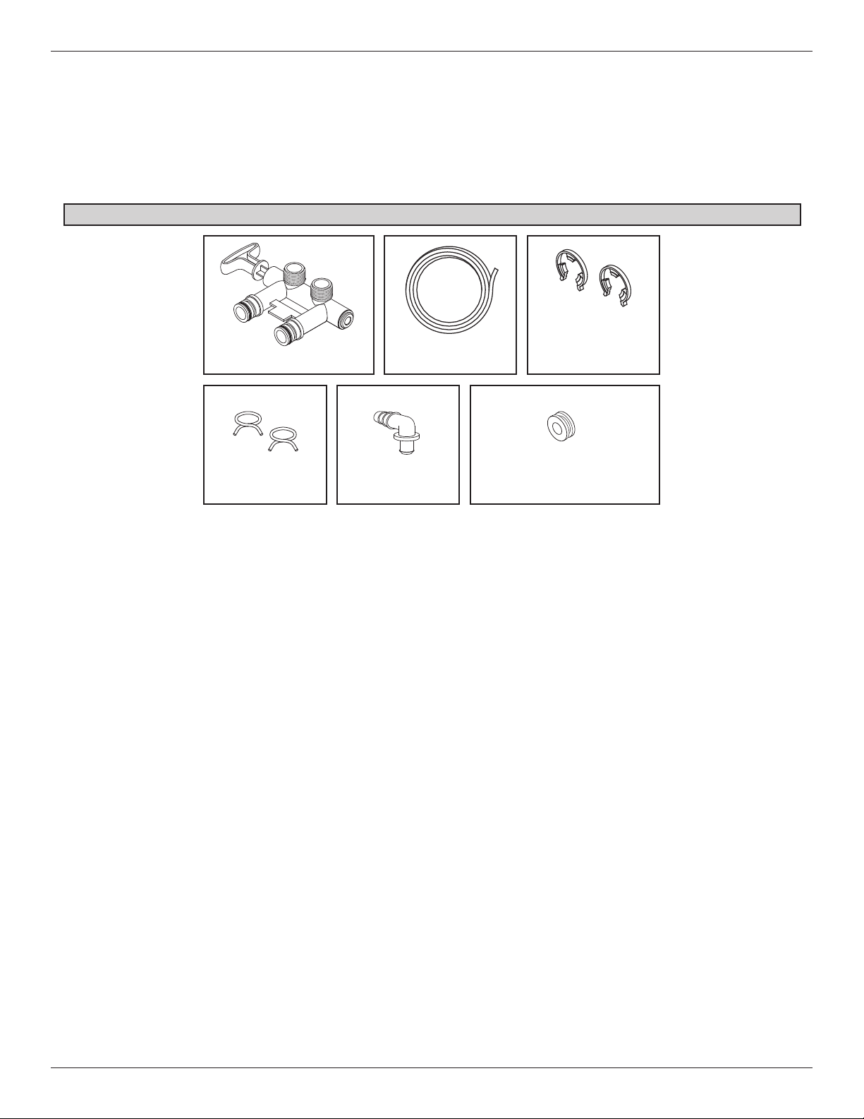
Inspect Shipment
The parts required to assemble and install the Central
Water Filtration System are included with the unit.
Thoroughly check the Central Water Filtration System
for possible shipping damage and parts loss. Also
inspect and note any damage to the shipping carton.
Packing List
Bypass Valve
Hose Clamps
Adaptor Elbow
Remove and discard (or recycle) all packing materials.
To avoid loss of small parts, we suggest you keep the
small parts in the parts bag until you are ready to use
them.
Clips
(shipped installed on
Drain Hose
North Star Water Softeners)
the softener’s valve)
Grommet (used for
FIG. 2
How a Central Water Filtration System Works
NORMAL OPERATION
During normal operation water enters the Central
Water Filtration System and flows through several filtration processes where tastes, odors and sediment
are reduced.
CLEAN RINSE CYCLE
A Clean Rinse cycle will automatically be initiated
based on how the controller has been programmed.
The Clean Rinse cycle lifts and expands the media
bed to rejuvenate the media and then repacks the bed
for continued use. During the Clean Rinse cycle, dirt,
sediment, etc. are flushed from the Central Water
Filtration System down the drain.
APPLICATIONS FOR A CENTRAL WATER
FILTRATION SYSTEM
= Do not use the Central Water Filtration System with
water that is microbiologically unsafe or of unknown
quality without adequate disinfection before or after
the system.
= The Central Water Filtration System may not be an
effective treatment method for water sources with a
hydrogen sulfide problem (rotten egg odor or taste)
If your water has hydrogen sulfide, contact a water
treatment expert or call 1-800-972-0135.
= The Central Water Filtration System will not remove
iron and is not intended to replace iron treatment
equipment.
= Although the Central Water Filtration System has
sediment filter capabilities, additional sediment filtration may be needed in problem water applications.
5

Installation Requirements
LOCATION REQUIREMENTS
Consider the following when selecting an installation
location for the Central Water Filtration System.
= Do not operate the Central Water Filtration System
where freezing temperatures occur. Do not attempt
to treat water over 100ºF (38ºC). Freezing temperatures or hot water damage voids the warranty.
= To condition all water in the home, install the
Central Water Filtration System close to the water
supply inlet, and before all other plumbing connections, except outside water pipes.
= For a home with municipal water supply, install the
Central Water Filtration System between the home’s
incoming water supply and the water softener, if one
is being used (See Figure 3A). If the home has well
water, reverse the order of the Central Water Filtra tion System and the water softener (See Figure 3B).
= A nearby drain is needed to carry away Clean
Rinse discharge water. Use a floor drain, laundry
THE PROPER ORDER TO INSTALL WATER TREATMENT EQUIPMENT
Untreated Water to
Cold Water
to House
Hot Water
to House
Outside Faucets
tub, sump, standpipe, or other options (check your
local codes). See "Air Gap Requirements" and
Valve Drain Requirements" sections. If a drain is
"
not available, it is still possible to operate the
Central Water Filtration System in a manual Clean
Rinse mode. See “Operating in Manual Clean
Rinse Mode.” The automatic Clean Rinse must be
disabled if the Central Water Filtration System will
not be connected to a drain (See Page 7).
= The Central Water Filtration System works on 24V
DC electrical power, supplied by a direct plug-in
power supply (included). Provide a 120V, 60 Hz
electrical outlet in accordance with NEC and local
codes.
= Do not install the Central Water Filtration System on
a hot water line (See Figures 3A & 3B, below).
= Avoid installing in direct sunlight. Excessive sun
heat may cause distortion or other damage to nonmetallic parts.
City Water Supply
Optional
Sediment
Filter
Cold Water
to House
Hot Water
to House
Water
Heater
Water
Heater
Untreated Water to
Outside Faucets
Central
Water
Filtration
System
Water
Softener
Water
Softener
Central
Water
Filtration
System
Optional
Sediment
Filter
6
Pressure
Tank
Well Water Supply
Well
Pump
FIG. 3A
OR
FIG. 3B

Installation Requirements
PLUMBING CODES
All plumbing must be completed in accordance with
national, state and local plumbing codes.
n the state of Massachusetts: The Commonwealth
I
of Massachusetts plumbing code 248-CMR shall
be adhered to. A licensed plumber shall be used
for this installation.
AIR GAP REQUIREMENTS
A drain is needed for Clean Rinse discharge water. A
floor drain, close to the Central Water Filtration
System, is preferred. A laundry tub, standpipe, etc.
are other drain options. Secure valve drain hose in
place. Leave an air gap of 1-1/2” between the end of
the hose and the drain. This gap is needed to prevent
backflow of sewer water into the Central Water
Filtration System . Do not put the end of the drain
hose into the drain.
CONNECTING VALVE TO DRAIN
VALVE DRAIN REQUIREMENTS
Using the flexible drain hose (included), measure and
cut to the length needed. Flexible drain hose is not
allowed in all localities (check your plumbing codes). If
local codes do not allow use of a flexible drain hose, a
rigid valve drain run must be used. Purchase a compression fitting (1/4 NPT x 1/2 in. minimum tube) and
1/2" tubing from your local hardware store. Plumb a
rigid drain as needed (see Figure 4, below).
NOTE: Avoid drain hose runs longer than 30 feet.
Make the valve drain line as short and direct
as possible.
It is recommended that the Central Water Filtration
System be installed near a drain. However, if a drain
is not available, it is still possible to operate the
Central Water Filtration System in a manual Clean
Rinse mode. See “Operating in Manual Clean Rinse
Mode” section. The automatic Clean Rinse function
must be disabled if the Central Water Filtration System
will not be connected to a drain.
Hose
Clamp
Drain
Fitting
Valve
Drain
Hose
Tie or wire
tubing in
place
To drain point other
than floor drain.
Support tubing in
place as needed.
Install adaptor
elbow using hose
clamp. Aim noz-
zle down toward
center of drain
1-1/2”
air gap
SUBSTITUTING RIGID DRAIN LINE
1/4 NPT Threads
Barbs
1/2” Outside Dia.
Clip
Cut barbs from
drain fitting (pull
clip to remove fit-
ting from valve)
1-1/2”
air gap
Comp Fitting. 1/4
NPT x 1/2” O.D.
Tube (not included)
1-1/2”
air gap
Copper Tube
(not included)
Drain grate with 1”
dia. hole in center
FLOOR DRAIN
7
LAUNDRY TUB STANDPIPE
FIG. 4

Installation Requirements
Electrical Shock Hazard
Prior to installation on metallic plumbing,
securely install two grounding clamps and a
#4 copper wire per installation instructions.
Failure to follow these instructions can result
in death or electrical shock.
3 VALVE BYPASS
INLET - OUTLET PLUMBING OPTIONS
Always install either a single bypass valve (provided),
as shown in Figure 7, or, if desired, parts for a 3 valve
bypass system (not included) can be purchased and
assembled, as shown in Figure 6. Bypass valves
allow you to turn off water to the Central Water
Filtration System for maintenance if needed, but still
have water in house pipes.
Use either:
= Copper pipe
= Threaded pipe
= PEX (Crosslinked Polyethylene) pipe
= CPVC plastic pipe
= Other pipe approved for use with potable water
IMPORTANT: Do not solder with plumbing attached to
the single bypass valve. Soldering heat
will damage the plastic valve.
CROSS OVER
Main Water Pi
Treated
Water from
Valve
OUTLET
pe
Untreated
Water to
Valve
INLET
In what direction
does the water flow?
Be sure to plan
piping so water
flow is to the
Central Water
Filtration System
valve INLET.
Plan a crossover
if flow is from left
to right.
Central Water Filtration
System
OUTLET
Central Water Filtration
System
INLET
CONNECTING PLUMBING TO VALVE
OUT
IN
Clips
Pipes
1” NPT Sweat
Adapter (2)
(not included)
Use Teflon® tape,
pipe joint compound or both
Bypass
Valve
Valve
Inlet
FIG. 6
FIG. 7
To Central Water
Filtration System
FIG. 5
8
 Loading...