

North Star NSC30UD1, NSC40UD1, NST45UD1, NST70UD1 Maintenance Manual
Ultra II COMPUTERIZED DEMAND
AUTOMATIC WATER CONDITIONER
NSC30UD1, NSC40UD1, NST45UD1 & NST70UD1
Installation
High Flow Valve
MODELS
Operation
Maintenance
Repair Parts
IF YOU HAVE QUESTIONS WHEN INSTALLING, OPERATING AND MAINTAINING YOUR
CONDITIONER, OR WHEN SETTING THE TIMER
CALLTOLLFREE: 1 -- 800 -- 972 -- 0135
IN CANADA CALL: 1 -- 800 -- 796 -- 6784
Systems tested and certified by NSF International
Systems tested and certified by the Water Quality
NORTH STAR WATER CONDITIONING, 1890 Woodlane Drive, Woodbury, MN 55125 Part No. 7332953 (Rev. F 5/14/13)
against NSF/ANSI Standard 44
for hardness reduction and efficiency,
and certified to NSF/ANSI Standard 372
Association against CSA B483.1.
Designed, Engineered &
Assembled in the U.S.A.
.

WATER CONDITIONER WARRANTY
Warrantor guarantees, to the original owner, that:
D For a period of one (1) year from the date of purchase, all parts will be free of defects in materials and workmanship, and will perform their
normal functions.
D For a period of one (1) year from the date of purchase, labor to repair or replace any part deemed to be defective in materials and workmanship, will be provided at no additional cost.
D For a period of ten (10) years from the date of purchase, the salt tank and fiberglass mineral tank will not rust, corrode, leak, burst, or in
any other manner, fail to perform their proper functions.
D For a period of three (3) years from the date of purchase, after installation, the electronic control board and valve body will be free of defects
in materials and workmanship, and will perform their normal functions.
If, during such respective period, a part proves to be defective, Warrantor will ship a replacement part, directly to your home, without charge.
After the first year, labor necessary to maintain this product is not covered by the product warranty.
Damage to any part of this water conditioner because of misuse, misapplication, neglect, alteration, accident, installation or operation contrary
to our printed instructions, or damage caused by any unusual force of nature such as, but not limited to, freezing, flood, hurricane, tornado, or
earthquake is not covered by this warranty. In all such cases, regular parts and service charges will apply.
Weassume no warranty liability in connection with this water conditioner other than specified herein. This warranty is in lieu of all other warranties,
expressed or implied, including warranties of fitness for a particular purpose. We do not authorize any person or representative to assume for
us any other obligations on the sale of this water conditioner.
Should a defect or malfunction occur, contact your contractor. If you are unable to contact your contractor, return the part, freight prepaid, directly
to the factory at the address below. Enclose with the part a full description of the problem, with your name, full address, date purchased, model
and serial numbers, and selling contractor’s name and address. We will repair or replace the part and return it to you at no cost if our repair department determines it to be defective under the terms of the warranty.
This warranty gives you specific legal rights and you may have other rights which vary from state to state.
This water conditioner is manufactured by North Star Water Conditioning, 1890 Woodlane Drive, Woodbury, MN, 55125; customer information
telephone no. 1--800--972--0135.
Warrantor: North Star Water Conditioning, 1890 Woodlane Drive, Woodbury, MN, 55125
One Year Full Warranty:
Limited Warranties:
General Conditions
SAFETY GUIDES
FOLLOW THE INSTALLATION INSTRUCTIONS CAREFULLY. FAILURE TO INSTALL THE S OFTENER PROPERLY VOIDS
THE WARRANTY.
BEFORE YOU BEGIN INSTALLATION, READ THIS ENTIRE MANUAL. THEN, OBTAIN ALL THE MATERIALS AND TOOLS
YOU WILL NEED TO MAKE THE INSTALLATION.
CHECK LOCAL PLUMBING AND ELECTRICAL CODES. THE INSTALLATION MUST CONFORM TO THEM. CODES IN
THE STATE OF MASSACHUSETTS REQUIRE INSTALLATION BY A LICENSED PLUMBER. FOR INSTALLATION, USE
PLUMBING CODE 248--CMR OF THE COMMONWEALTH OF MASSACHUSETTS.
USE ONLY LEAD--FREE S OLDER AND FLUX FOR ALL SWEAT--SOLDER CONNECTIONS, AS REQUIRED BY STATE
AND FEDERAL CODES.
USE CARE WHEN HANDLING THE SOFTENER. DO NOT TURN UPSIDE DOWN, DROP, OR SET ON SHARP PROTRUSIONS.
DO NOT LOCATE THE SOFTENER WHERE FREEZING TEMPERATURES OCCUR. DO NOT ATTEMPT TO TREAT WATER OVER 120F. FREEZING, OR HOT WATER DAMAGE VOIDS THE WARRANTY.
AVOID INSTALLING IN DIRECT SUNLIGHT. EXCESSIVE SUN HEAT MAY CAUSE DISTORTION OR OTHER DAMAGE TO
NON--METALLIC PARTS.
THE SOFTENER REQUIRES A MINIMUM WATER FLOW OF 3 GALLONS PER MINUTE AT THE INLET. MAXIMUM AL-
LOWABLE INLET WATER PRESSURE IS 125 PSI. IF DAYTIME PRESSURE IS OVER 80 PSI, NIGHTTIME PRESSURE
MAY EXCEED THE MAXIMUM. USE A PRESSURE REDUCING VALVE IF NECESSARY. ( ADDING A PRESSURE REDUCING VALVE MAY REDUCE THE FLOW.)
THE SOFTENER WORKS ON 24 VOLT-- 60 Hz ELECTRICAL POWER ONLY. BE S URE TO USE THE INCLUDED TRANSFORMER AND PLUG IT INTO A NOMINAL 120V, 60 CYCLE HOUSEHOLD OUTLET THAT IS GROUNDED AND PROPERLY
PROTECTED BY AN OVER CURRENT DEVICE SUCH AS A CIRCUIT BREAKER OR FUSE. IF TRANSFORMER IS REPLACED, USE ONLY THE AUTHORIZED SERVICE, CLASS II, 24 VOLT, 10VA TRANSFORMER.
THIS SYSTEM IS NOT INTENDED TO BE USED FOR TREATING WATER THAT IS MICROBIOLOGICALLY UNSAFE OF
OF UNKNOWN QUALITY WITHOUT ADEQUATE DISINFECTION BEFORE OR AFTER THEY SYSTEM.
EUROPEAN DIRECTIVE 2002/96/EC REQUIRES ALL ELECTRICAL AND ELECTRONIC EQUIPMENT TO BE DISPOSED OF ACCORDING TO WASTE ELECTRICAL AND ELECTRONIC EQUIPMENT (WEEE) REQUIREMENTS.
THIS DIRECTIVE OR SIMILAR LAWS ARE IN PLACE NATIONALLY AND CAN VARY FROM REGION TO REGION.
PLEASE REFER TO YOUR STATE AND LOCAL LAWS FOR PROPER DISPOSAL OF THIS EQUIPMENT.
2

UNPACKING / INSPECTION
The softener is shipped in one carton (most models)
or two cartons (model NST70UD1 only). It is completely assembled at the factory, except as required
at installation.
Be sure to check the entire softener for any shipping
damage or parts loss. Also note damage to the shipping cartons. Contact the transportation company
for all damage and loss claims. The manufacturer is
not responsible for damages in transit.
Small parts, needed to install the softener, are in a
parts bag. To avoid loss of the small parts, keep
them in the parts bag until you are ready to use
them.
TABLE OF CONTENTS
PAGE N O.
WARRANTY, SAFETY GUIDES 2........................................................
SPECIFICATIONS AND PERFORMANCE CLAIMS 4.......................................
DIMENSIONS 5.......................................................................
BEFORE STARTING INSTALLATION 6...................................................
TYPICAL INSTALLATION ILLUSTRATION 7..............................................
INSTALLATION STEPS 8 -- 10...........................................................
PROGRAMMING THE
SANITIZING PROCEDURES 12.........................................................
WATER AND WATER CONDITIONING 13 -- 14............................................
HOW THE WATER SOFTENER WORKS 14 -- 15...........................................
GENERAL WATER SOFTENER MAINTENANCE 16 -- 17...................................
ELECTRONIC DEMAND TIMER FEATURES, SETTINGS AND SERVICE
DISPLAYS, OPTIONAL RECHARGE CONTROLS, PROGRAM MEMORY 18 -- 19..........
RECHARGE (START) TIME, MAXIMUM DAYS BETWEEN REGENERATIONS,
EFFICIENCY MODE, 97% FEATURE, HEAVY DUTY BACKWASH 19 -- 20................
MODEL CODE, 12 OR 24 HOUR CLOCK, GALLONS OR LITERS MEASURE 21..........
AUTOMATIC ELECTRONIC DIAGNOSTICS 22........................................
ELECTRONIC SYSTEM PROFILE, HOW TO SEND AN ESP TRANSMISSION 22 -- 23.....
SERVICE CHECKOUT PROCEDURES 24............................................
MANUAL INITIATED ELECTRONICS DIAGNOSTIC 24 -- 25.............................
MANUAL ADVANCE REGENERATION CHECK 25.....................................
WIRING SCHEMATIC 25............................................................
WATER FLOW THROUGH VALVE 26....................................................
REPAIR PARTS 28 -- 31.................................................................
Ultra II ELECTRONIC DEMAND TIMER 11 -- 12.....................
3
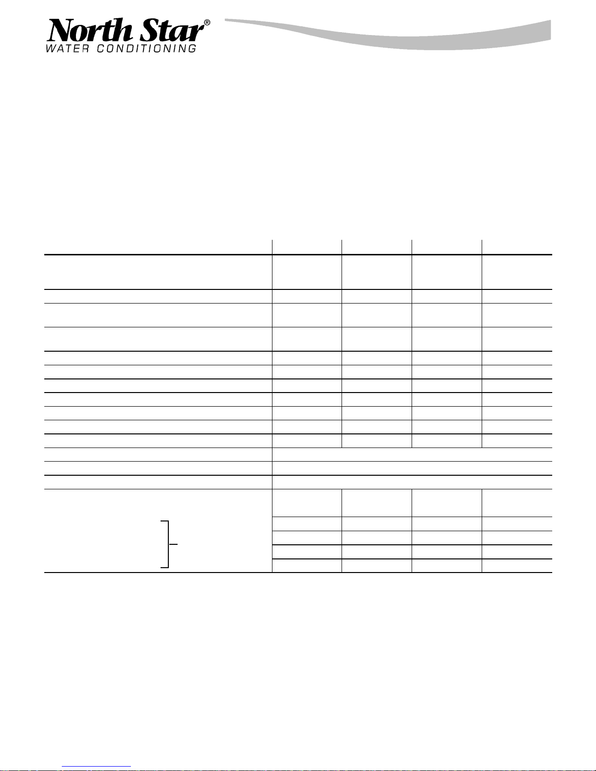
SPECIFICATIONS AND PERFORMANCE CLAIMS
These models are efficiency rated. The efficiency rating is valid only at the minimum salt dose. These
softeners have a demand initiated regeneration (D.I.R.) feature that complies with specific performance
specifications intended to minimize the amount of regenerant brine and water used in their operation.
These softeners have a rated softener efficiency of not less than 3,350 grains of total hardness exchange
per pound of salt (based on sodium chloride) and shall not deliver more salt than their listed rating or be
operated at a sustained maximum service flow rate greater than their listed rating. These softeners have been
proven to deliver soft water for at least ten continuous minutes at the rated service flow rate. The rated salt
efficiency is measured by laboratory tests described in NSF/ANSI Standard 44. These tests represent the
maximum possible efficiency that the system can achieve. Operational efficiency is the actual efficiency after
the system has been installed. It is typically less than the rated efficiency, due to individual application factors
including water hardness, water usage, and other contaminants that reduce a softener’s capacity.
MODEL NSC30UD1 NSC40UD1 NST45UD1 NST70UD1
RATED CAPACITY (grains @ lbs salt dose) 10,100 @ 2.0
27,000 @ 7.6
34,300 @ 13.2
RATED EFFICIENCY (grains / lb @ min. salt dose) 5,030 @ 2.0 5,100 @ 2.3 5,120 @ 2.6 5,110 @ 4.1
WATER USED DURING REGENERATION (gallons)
@ MINIMUM SALT DOSE
TOTAL WATER USED PER REGENERATION (gallons)
@ MAXIMUM SALT D O SE
AMOUNT OF HIGH CAPACITY RESIN (lbs / cu ft) 50.4 / .97 56.2 / 1.08 65.5 / 1.26 101 / 1.94
RESIN TANK NOMINAL SIZE (in., dia x height) 9x40 9x40 10 x 40 12 x 54
SERVICEFLOWRATE(gpm) 7.5 10.0 10.0 13.5
PRESSURE DROP AT SERVICE FLOW (psi) 9 14 11.2 15
INTERMITTENT FLOW RATE @ 15 psi (gpm) Y 11.0 10.2 12.1 13.5
WATER SUPPLY MAXIMUM HARDNESS (gpg) 110 110 120 120
WATER SUPPLY MAX. CLEAR WATER IRON (ppm) H 5 5 12 19
WATER PRESSURE LIMITS (min. / max. psi) F 20 --- 125
WATER TEMPERATURE LIMITS (_F) 40 --- 120
WATER SUPPLY MINIMUM FLOW RATE (gpm) 3
REGENERATION CYCLE FLOW RATES (gpm)
FILL (flow to brine tank)
BRINING
BRINE RINSE
MAX. BACKWASH
MAX. FAST RINSE
(flow to drain)
4.0 /
1,000 grains
40.0 38.3 56.0 101
.3 .3 .3 .3
0.22 0.22 0.22 0.33
0.15 0.15 0.15 0.22
2.0 2.0 2.0 2.6
2.0 2.0 2.0 2.6
11,700 @ 2.3
30,800 @ 8.5
39,000 @ 14.7
3.3 /
1,000 grains
13,300 @ 2.6
35,700 @ 9.9
45,400 @ 17.2
4.1 /
1,000 grains
21,000 @ 4.1
55,100 @ 15.2
70,000 @ 26.4
4.3 /
1,000 grains
Y Intermittentflow rate does not represent the maximum serviceflow rateused for determining the softeners rated capacity and efficien-
cy. Continuous operation at flow rates greater than the service flow rate may affect capacity and efficiency performance.
H Capacity to reduce clear water iron is substantiated by WQA test data.
F Canada working pressure: 1.4 -- 7.0 kg/cm@.
These systems conform to NSF/ANSI 44 for specific performance claims as verified and substantiated by test data.
4
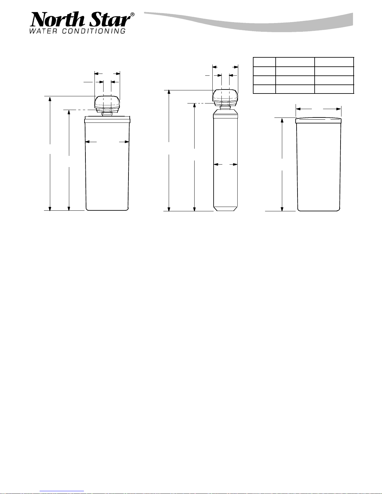
DIMENSIONS
14”
3--7/8”
OUT
INLET
INLET -- OUTLET
18-- 1/4”
50-- 3/8”
41-- 5/8”
NSC30UD1 & NSC40UD1
3--7/8”
INLET -- OUTLET
A
B
14”
A 50--3/8” 64”
B 41--5/8” 55--1/2”
NST45UD1 NST70UD1
OUT
INLET
C
C 11” 13”
39”
NST45UD1 & NST70UD1
18”
5

BEFORE STARTING INSTALLATION
" WHERETOINSTALLTHESOFTENER ................................................
S Place the softener as close as possible to the
pressure tank (well system) or water meter (city
water).
S Put the softener in a place water damage is least
likely to occur if a leak develops. The manufacturer will not repair or pay for water damage.
S Place the softener as close as possible to a floor
drain, or other acceptable drain point (laundry
tub, sump, standpipe, etc.).
S Connect the softener to the main water supply
pipe BEFORE or AHEAD OF the water heater.
DO NOT RUN HOT WATER THROUGH THE
SOFTENER. Temperature of water passing
through the softener must be less than 120_F
(49_C).
S Keep outside faucets on hard water to save soft
water and salt.
S Do not install the softener in a place where it
could freeze. Damage caused by freezing is
not covered by the warranty.
S A 120 volt AC electrical outlet, to plug the in-
cluded transformer into, is needed near the softener. The transformer has an attached power
cable. Be sure the electric outlet and trans-
former are in an inside location, to protect
from wet weather.
S If installing in an outside location, you must take
the steps necessary to assure the softener,
installation plumbing, wiring, etc., are as well
protected from the elements, contamination,
vandalism, etc., as when installed indoors.
S Keep the softener out of direct sunlight. The
sun’s heat may soften and distort plastic parts.
" TOOLS,PIPEandFITTINGS,OTHERMATERIALSYOUWILLNEED(seepage6) ........
GPlastic inlet and outlet fittings included with the
softener allow water flow equivalent to 1” (nominal)
pipe. To maintain full valve flow, 1” pipes to and from
the softener fittings are recommended. You should
maintain the same, or larger, pipe size as the water
supply pipe, up to the softener inlet and outlet.
GDrain hose (3/8” inside diameter) is needed for the
valve drain. See step 5 on page 8. A 15’ length of
hose is included with some models.
GIf a rigid valve drain is needed, to comply with
plumbing codes, you can buy the parts needed (see
page 8) to connect a 1/2 in. copper tubing drain.
GUse copper, brass, or galvanized pipe and fittings.
Some codes may also allow PVC plastic pipe.
GALWAYS install the included bypass valve, or 3
shut-off valves. Bypass valves let you turn off water
to the softener for repairs if needed, but still have
water in the house pipes.
" PLANHOWYOUWILLINSTALLTHESOFTENER .....................................
You must first decide how to run in and out pipes to
the softener. Look at the house main water pipe at
the point where you will connect the softener. Is the
pipe soldered copper, glued plastic, or threaded
brass/galvanized? What is the pipe size?
6
GA length of 3/8” or 7/16” inside diameter hose is
needed for the salt tank drain. A 7’ length of hose is
included with some models. If a longer length is
needed, you can buy good quality, thick--wall, flexible hose at most hardware stores or supply houses.
GNugget or pellet water softener salt is needed to fill
the brine tank (see page 9, 10 and 16).
Now look at the typical installation illustration on
page 6. Use it as a guide when planning your particular installation. Be sure to direct raw, hard water
to the softener valve inlet fitting. The valve is
marked IN and OUT.
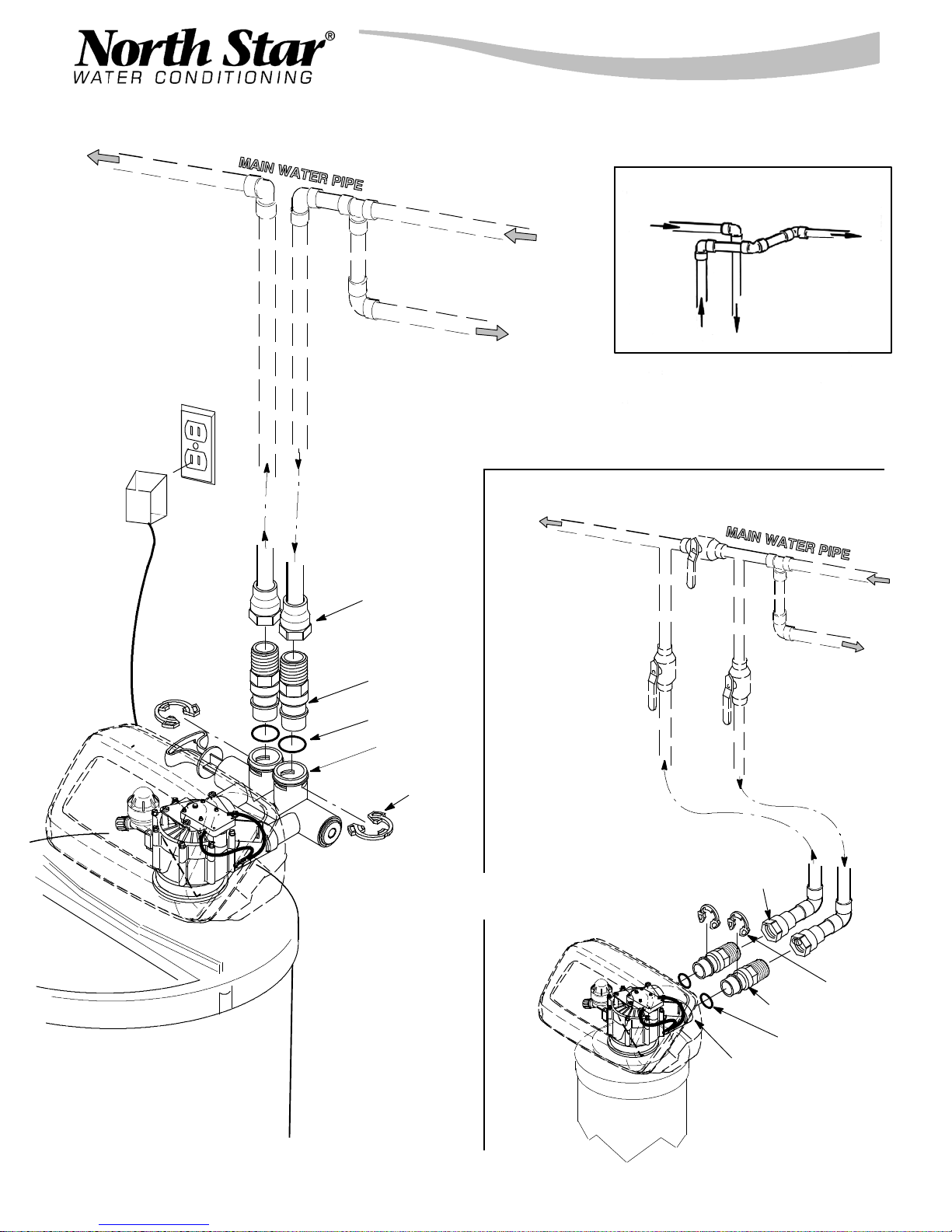
TYPICAL SOLDERED COPPER or CPVC INSTALLATIONS
soft water
120 Volt
outlet
1” NPT sweat
adaptor (2)
not included
Use if water supply flows from the left.
Include single or 3 -- valve bypass.
hard water
hard water to
outside faucets
HARD
WATER
FROM
SOFTENER
OUTLET
WATE R
TO SOFTENER
INLET
INSTALLATION USING 3 -- VALVE BYPASS
(BRINE TANK NOT SHOWN)
BYPASS
valve
CROSS -- OVER
SOFT
1” NPT installa-tion adaptor (2) *
o-- ring seal (2) *
Bypass Valve *
clip (4) *
* included with softener -- Pipe and
fittings supplied by installer.
OUTLET
valve
INLET valve
D for soft water SERVICE:
-- O p e n the inlet and outlet
valves.
-- C l o s e the bypass valve.
D for hard water BYPASS:
-- C l o s e the inlet and outlet
valves.
-- O p e n the bypass valve.
1” NPT sweat
adaptor (2)
not included
clip (2) *
1” NPT installa-tion adaptor (2) *
o-- ring seal (2) *
VALVE
INLET
7
INSTALLATION STEPS
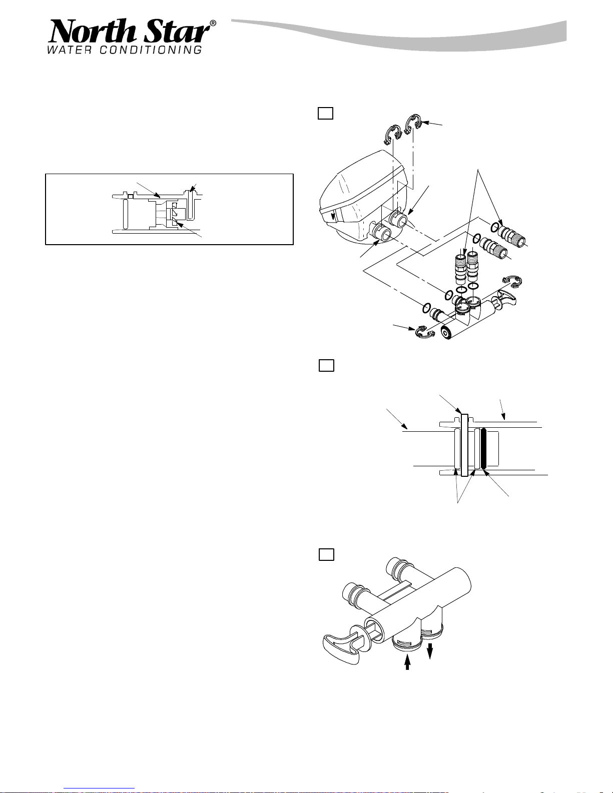
1. INSTALL BYPASS VALVE and/or PLASTIC
INSTALLATION ADAPTORS:
NOTE: Before installing the bypass valve or plastic
installation adaptors, be sure the turbine and support are
firmly in place, in the valve outlet. Blow into the valve port
and observe the turbine for free rotation.
turbine support
sensor port
turbine
" Push the bypass valve, with lubricated o--ring
seals in place, into the valve inlet and outlet ports,
Figures 1A and 1C.
-- AND/OR --
" Slide plastic installation adaptors, with lubricated
o--ring seals in p lace, into the softener valve or
bypass valve inlet and outlet ports, Figure 1A.
" Snap the two large plastic clips in place, from the
top down, Figures 1A and 1B. Be sure they snap
into place. Pull on the plastic installation
adaptors,or bypass valve, to make sure they are
held securely in place.
2. INSTALL THE BRINE TANK OVERFLOW FIT-
TINGS:
" Insert the rubber grommet into the 3/4” diameter
hole in the brine tank sidewall, see page 10.
" Push the barbed end of the hose adaptor elbow
into the grommet.
FIGURE 1
A
INLET
clip (2)
B
bypass valve or
plastic adaptor
clip (2)
OUTLET
clip
plastic installation adaptors
(install in softener valve or
bypass valve)
bypass
valve
cross section of
valve inlet or outlet
3. MOVE THE SOFTENER ASSEMBL Y (CAB-
INET MODEL), OR RESIN TANK (TWO TANK
MODEL) INTO INSTALLATION POSITION:
" Be sure the installation surface is level and
smooth. If needed, place the tank on a section of
3/4” thick (min.) plywood. Then, place shims under
the plywood as needed to level the softener.
4. PLUMB IN AND OUT PIPES TO AND FROM
SOFTENER:
CAUTIONS: Observe all of the following cautions
while you connect inlet and outlet plumbing.
" T urn off the house water supply valve and
open faucets to relieve pressure in the pipes.
" BE SURE RAW,
TO THE VALVE INLET PORT.
" Be sure to use bypass valve(s).
NOTE: CHECK LOCAL PLUMBING AND ELECTRICAL CODES. THE INSTALLATION MUST CONFORM
TO THEM. In Massachusetts, plumbing codes of Massachusetts shall be adhered to. Consult with your licensed plumber.
8
HARD WATER IS DIRECTED
C
clip snaps into place
between larger diameter rings
Turn bypass valve
upside down to
connect to floor level
plumbing.
OUT
IN
o--ring
INSTALLATION STEPS, continued
" If making a soldered copper installation, do all
sweat soldering before connecting pipes to the
softener fittings. Torch heat will damage plastic
parts.
" When turning threaded pipe fittings onto plastic
fittings, use care not to cross--thread.
" Use pipe joint compound on all external pipe
threads.
" Support inlet and outlet plumbing in some man-
ner (use pipe hangers) to keep the weight off of the
valve fittings.
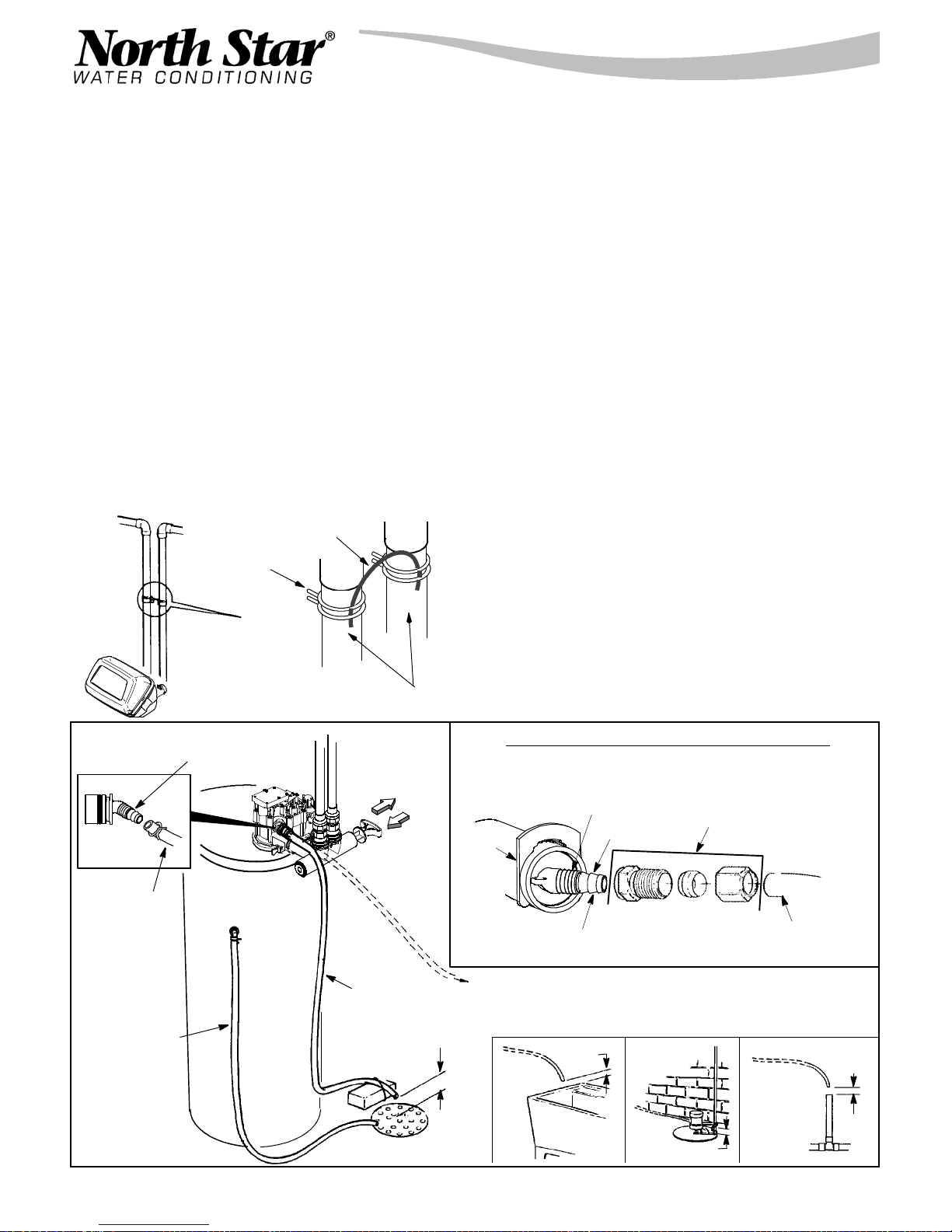
5. INSTALL GROUNDING WIRE (IF NEEDED):
" To maintain electrical ground continuity in the
house cold water piping, install a #4 copper wire
across the removed pipe section, securelyclamping
it at both ends (see Figure 2) -- parts not included.
FIGURE 2
ground wire
hose clamp
ground (2)
6. CONNECT AND RUN THE VALVE DRAIN
HOSE:
" Take a length of 3/8” inside diameter hose and
attach to the valve drain fitting.
" Locate the other end of the hose at a suitable
drain point...floor drain, sump, laundry tub, etc.
Check and comply with local codes.
IMPORTANT: If a longer length of hose is needed,
buy and use high quality, thick--wall hose that will
not easily kink or collapse. The water softener will
not work if water cannot exit this hose during regenerations.
" Tie or wire the hose in place at the drain point.
Water pressure will cause it to whip during the backwash and fast rinse cycles of regeneration. Also provide an air gap of at least 1 --1/2” between the end of
the hose and the drain point. An air gap prevents
possible siphoning of sewer water, into the softener,
if the sewer should back up.
FIGURE 3
valve drain
hose
overflow
drain hose
drain fitting
adaptor
inlet -- outlet
pipes
PULL OUT
for soft water
‘‘service’’
PUSH IN
for bypass
valve drain
hose
" If raising the drain hose overhead is required to
get to the drain point, do not raise higher than 8’
above the floor. Elevating the hose may cause a
back-- pressure that could reduce brine draw during
regenerations.
CONNECTING A RIGID VALVE DRAIN TUBE
To adapt a copper drain tube to the softener, buy a compression fitting (1/4 NPT x 1/2”O.D. minimum tube) and needed tubing from
your local hardware store.
1/4” NPT thread
1-- 1/2”
air gap
barbs
Clip
Cut barbs from valve drain elbow (pull clip
and remove drain valve elbow from valve)
To standpipe, sump,
laundry tub or other
1-- 1/2”
air gap
approved drain.
Compression fitting 1/4 NPT x
1/2” O.D. tube
1/2” outside diameter
copper tube
SUMP
continued
1-- 1/2”
air gap
FLOOR DRAIN
LAUNDRY
TUB
STANDPIPE
1--1/2” air gap
9
INSTALLATION STEPS, continued
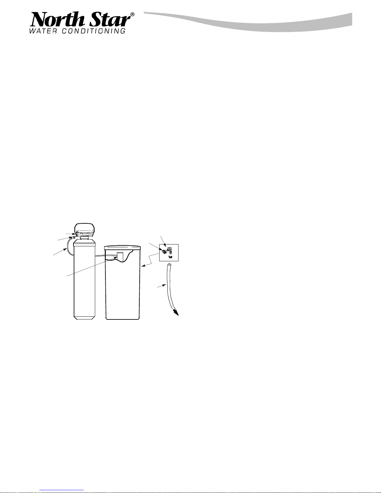
7. CONNECT AND RUN THE BRINE TANK
OVERFLOW HOSE:
This drain is for safety only. If the brine tank should
over-- fill with water, the excess is carriedto the drain.
" Attach a length of hose (included with somemodels) to the drain elbow, installed in step 2, page 8.
Useahoseclamptoholditinplace.
" Locate the other end of the hose at the drain
point. Do not elevate this hose higher than the elbow on the brine tank. Do not tee this hose to the
valve drain hose.
8. ON TWO TANK MODELS, CONNECT BRINE
TUBING:
" Route the brine tubing out, through the largest
hole in the brine tank sidewall. Connect the tubing
to the nozzle housing, as shown in Figure 4, using
a nut--ferrule. Tighten the nut, by hand only.
FIGURE 4
nozzle/venturi
nut--ferrule
brine
valve tubing
grommet
hose
adaptor
D. Place bypass valve(s) in ‘‘service”, EXACTLY
as follows. KEEP SOFT WATER FAUCETS OPEN.
1. SINGLE BYPASS VALVE: SLOWLY, pull the
valve stem outward to ‘‘service’’, pausing several
times to allow the softener to pressurize slowly.
2. 3-- VALVE BYPASS: Fully close the bypass
valve and open the outlet valve. SLOWLY, open
the inlet valve, pausing several times to allow the
softener to pressurize slowly.
E. After about three minutes, open a HOT water
faucet for one minute, or until all air is expelled, then
close.
F. Close both cold water faucets.
G. Check your plumbing work for leaks and fix right
away, if any are found. Be sure to observe previous
caution notes.
H. Turn on the gas or electric supply to the water
heater. Light the pilot, if applicable.
10. ADD WATER AND SALT TO THE BRINE
TANK:
" Remove the salt storage area cover. Add about
three gallons of water into the tank. Do not add into
the brinewell.
brinewell
over-
flow
drain
hose
to floor
drain
9. FLUSH PIPES, EXPEL AIR FROM SOFTENER,
AND TEST YOUR INSTALLATION FOR WATER
LEAKS:
CAUTION: To avoid water or air pressure damage to softener inner parts, be sure to do the following steps exactly as listed.
A. Fully open two cold, soft water faucets nearby
the softener.
B. Place bypass valve(s) in ‘‘bypass’’ position. On
a single valve, slide the stem inward to BYPASS,
see page 9. On a 3--valve system, close the inlet
and outlet valves, and open the bypass valve, see
page 7.
C. Fully open the house main water pipe shutoff
valve. Observe a steady flow from both opened faucets.
" Fill the tank with NUGGET, PELLET or coarse
SOLAR water softener salt. Do not use rock, block,
granulated, and ice cream making salts, or salt with
iron removing additives. Also see page 16. Salt
storage capacity is 200 lbs or more (varies by mod-
el). For best results, North Star recommends MortonR System SaverR Pellets for use in this water
softener.
Note: If the softener is installed in a humid basement
or other damp area, it is better to fill the tank withless
salt, morefrequently (see salt bridgingin the maintenance section). Eighty to 100 lbs of salt will last for
several months, depending on water hardness,
family size, and model of softener.
11. CONNECT TO ELECTRICAL POWER:
" The softener works on 120 volt, 60 Hz electric
power. The included transformer changes standard
120 volt AC house power to 24 volts. Plug the trans-
former into a 120 volt outlet only. Be sure the outlet is always ‘‘live’’ so it can not be switched off by
mistake.
12. PROGRAM THE Ultra II DEMAND TIM-
ER, page 11.
10
 Loading...