

North Star M459231B.1 Maintenance Manual
Quick Facts
Pump Oil
Check pump oil level before starting.
Use Non-detergent pump oil (part #35605).
Air Filter
Make sure your air filter is clean and particle free.
Replacement air filter (part #35409).
Maximum
Pressure
Maximum pressure = 175 psi
Maintenance
Schedule
Tank:
Drain water daily.
Compressor
Pump:
Oil: change after first 50 hours, then every 3 months or 500 hours.
Read and understand all manuals before operating.
M459231B.1
459231; 5 HP Leeson, 19.2 PSC, 80 gal.
459241; 7.5 HP Leeson, 29.5 PSC, 80 gal.
M35643K.2
®
Electric Stationary Air Compressor
Installation, Operation and Maintenance Manual
To the Owner:
Thank you for purchasing a NorthStar Air Compressor. Your machine is designed for long life, dependability, and
the top performance you demand! Please take time now to read through this manual so you better understand
the machine’s operation, maintenance and safety precautions. Everyone who operates this machine must read
and understand this manual. The time you take now will prolong your machine’s life and prepare you for its safe
operation. Enjoy the exceptional performance of your NorthStar Air Compressor, the industry leader!
The manufacturer reserves the right to make improvements in design and/or changes in specifications at any
time without incurring any obligation to install them on units previously sold.
Any Questions, Comments, Problems, or Parts Orders
Call NorthStar Product Support 1-800-270-0810
2
Table of Contents
Important Safety Instructions
2
Operation
6
Receipt and Inspection
2
Maintenance / Kits & Service Parts
7
Machine Component Identification
3
Exploded View / Component List
8-11
Installation
4, 5
Troubleshooting
12
Wiring Installation
5
Limited Warranty
13
Safety
DEFINITIONS
DANGER!
WILL cause DEATH, SEVERE INJURY or substantial
property damage.
WARNING!
CAN cause DEATH, SEVERE INJURY or substantial
property damage.
CAUTION!
WILL or CAN cause MINOR INJURY or property
damage.
GENERAL SAFETY PRECAUTIONS
NEVER directly inhale compressed air.
NEVER over-pressurize the receiver tank or similar
vessels beyond design limits.
NEVER use a receiver tank or similar vessels that fail to
meet the design requirements of the compressor.
NEVER drill into, weld or otherwise alter the receiver
tank or similar vessels.
NEVER remove, adjust, bypass, change, modify or make
substitutions for safety/relief valves, pressure switches or
other pressure control related devices.
NEVER use air tools or attachments without first
determining the maximum pressure recommended for
that equipment.
NEVER point air nozzles or sprayers toward people or
animals.
NEVER touch the compressor pump, motor or engine or
discharge tubing during or shortly after operation. These
parts become hot.
NEVER operate where flammable or explosive liquids or
vapors such as gasoline, natural gas and solvents are
present.
NEVER remove, paint over, or deface decals. Replace
any missing decals.
NEVER operate with guards or shields removed,
damaged or broken.
ALWAYS follow precautions on container labels before
spraying such as paint , insecticide and weed killer.
ALWAYS wear respirator and safety glasses when
spraying.
ALWAYS wear eye protection when operating or
servicing compressor.
BREATHING AIR PRECAUTION
NorthStar air compressors are not designed, intended
or approved for breathing air. Compressed air should not
be used for breathing air applications unless treated in
accordance with all applicable codes and regulations.
Receipt and Inspection
Ensure adequate lifting equipment is available for
unloading and moving your compressor to the
installation site.
NOTE: Lifting equipment must be properly rated for the
weight of the compressor.
Caution! Do not work on or walk under the compressor
while it is suspended. Before signing the delivery receipt,
inspect for damage and missing parts. If damage or
missing parts are apparent, make the appropriate
notation on the delivery receipt, then sign the receipt.
Immediately contact the carrier for an inspection. All
material must be held in the receiving location for the
carrier’s inspection. Delivery receipts that have been
signed without a notation of damage or missing parts are
considered to be delivered “clear” Subsequent claims are
then considered to be concealed damage claims. Settle
damage claims directly with the transportation company.
If you discover damage after receiving the air
compressor (concealed damage), the carrier must be
notified within 15 day of receipt and an inspection must
requested by telephone with confirmation in writing. On
concealed damage claims, the burden of establishing
that the compressor was damaged in transit reverts back
to the claimant.
Read the compressor nameplate to verify it is the model
ordered, and read the motor nameplate to verify it is
compatible with your electrical conditions. Make sure
electrical enclosures and components are appropriate.
WARNING! The installation should be made by a
qualified electrician.
3
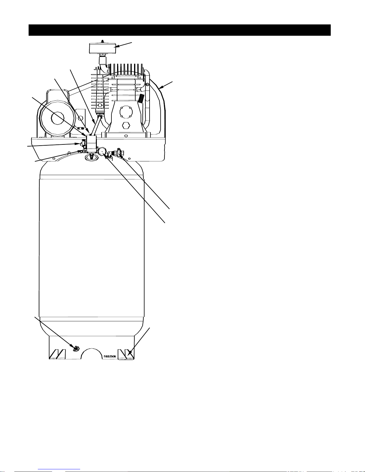
Machine Component Identification
10
9 8 12
11
2
7
1
4
5
6
1.) Air Filter - Make sure your air filter is clean and
particle free.
2.) Belt Guard - Covers the belt, motor pulley and
flywheel. NEVER operate compressor without the
belt guard or guard cover.
4.) Ball Valve - 1/2” NPT outlet.
5.) Pressure Gauge - Easy to read gauge.
6.) Mount Feet - Use an isolation pad system to
increase your compressor life.
7.) Remote Drain Petcock - This valve is located on
the foot ring of the tank. Use this valve to drain
moisture from the tank daily to reduce the risk of
corrosion.
8.) ASME Safety Valve - This valve automatically
releases air if the tank pressure exceeds the preset
maximum.
9.) Unloader - Device on pressure switch which
allows release of pressurized air between the tank
and compressor so motor does not start under load.
10.) Pressure Switch - Auto/Off Switch - In the
“auto” position, the compressor shuts off
automatically when tank pressure reached the
maximum preset pressure. In the “off” position, the
compressor will not operate. This switch should be
in the “off” position when connecting or
disconnecting the power cord from the electrical
outlet. NEVER attempt to adjust the pressure switch.
Tampering with the pressure switch will void ALL
warranties.
11.) Check Valve - One-way valve that allows air to
enter the tank, but prevents air in the tank from
flowing back into the compressor pump.
12.) Discharge Tube - This tube carries
compressed air from the pump to the check valve.
This tube becomes very hot during use. To avoid
the risk of severe burns, never touch the discharge
tube.
4
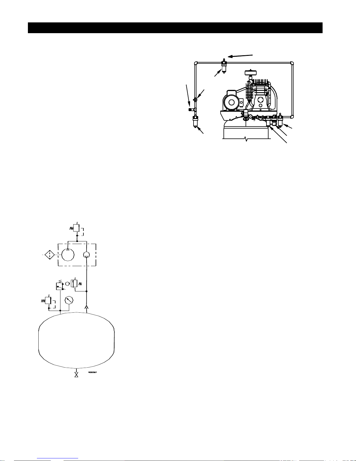
80-Gallon Tank
Safety Relief
Valve
34796 Pump (Item #459231)
34798 Pump (Item #459241)
Pressure
Switch
Safety
Relief
Valve
Note:
Pressure switch automatically activates the unloader.
SLOPE
TRAP
REGULATOR
FILTER/TRAP
TRAP
OUTLET
VALVE
00855
Installation
SELECTING A LOCATION
Select a well lit indoor area with plenty of space for
proper cooling air flow and accessibility. Locate the
compressor at least 15 inches (38 cm) from walls,
and make sure the power supply is clearly identified
and accessible.
Temperature. Ideal operating temperatures are
between 40 and 100F (4 and 37 C). If
temperatures consistently drop below 32 F (0 C),
install the compressor inside a heated building. If this
is not possible, you must protect safety/relief valves
and drain valves from freezing.
CAUTION!
NEVER operate in temperatures below 15 F (-9C)
or above 125 F (52C).
Humid Areas. In frequently humid areas, moisture
may form in the pump and produce sludge in the
lubricant, causing running parts to wear out
prematurely. Excessive moisture is especially likely
to occur if the compressor is located in an unheated
area that is subject to large temperature changes.
PNEUMATIC SCHEMATIC
INSTALLING DISCHARGE PIPING
CAUTION! If you will be using synthetic lubricant, all
downstream piping material and system components
must be compatible. Refer to suitable list on page 6.
General Requirements. The piping, fittings, etc.
must be certified for at least 4 times the working
pressure. Use hard-welded, threaded steel or copper
pipes and cast iron fittings that are certified safe for
the compressors discharge pressure and
temperature. DO NOT USE PVC PLASTIC. Use pipe
thread sealant on all threads, and make up joints
tightly to prevent air leaks.
Main Air Distribution Line. The main compressed
air distribution line should be of sufficient size to
minimize the pressure drop between the air supply
and the point of use. Slope the piping downward in
the direction of air flow to aid in the removal of
condensation at all drain points along the line. The
piping must be as short and direct as possible, and
adequately braced.
Drip Legs. A drip leg is a pipe extending downward
from the main line to collect condensation. Drip legs
should be at the lowest points in the air line and at
any point where the leg goes around an obstruction.
A drain valve should be installed at the bottom of
each drip leg.
Drop Legs. A drop leg is piping originating from the
main air distribution line that feeds air to an outlet for
tools or other air operated devices. Drop legs are
taken off the top of the main line so that
condensation does not easily flow into them. Drop
legs should be designed so that the air outlet comes
off the side of the drop leg, rather than the bottom.
By doing this, the condensation which is carried from
the main line collects below the outlet and prevents
moisture from entering the tool or device using the
air. A drain valve should be installed on the bottom of
each drop leg.
5
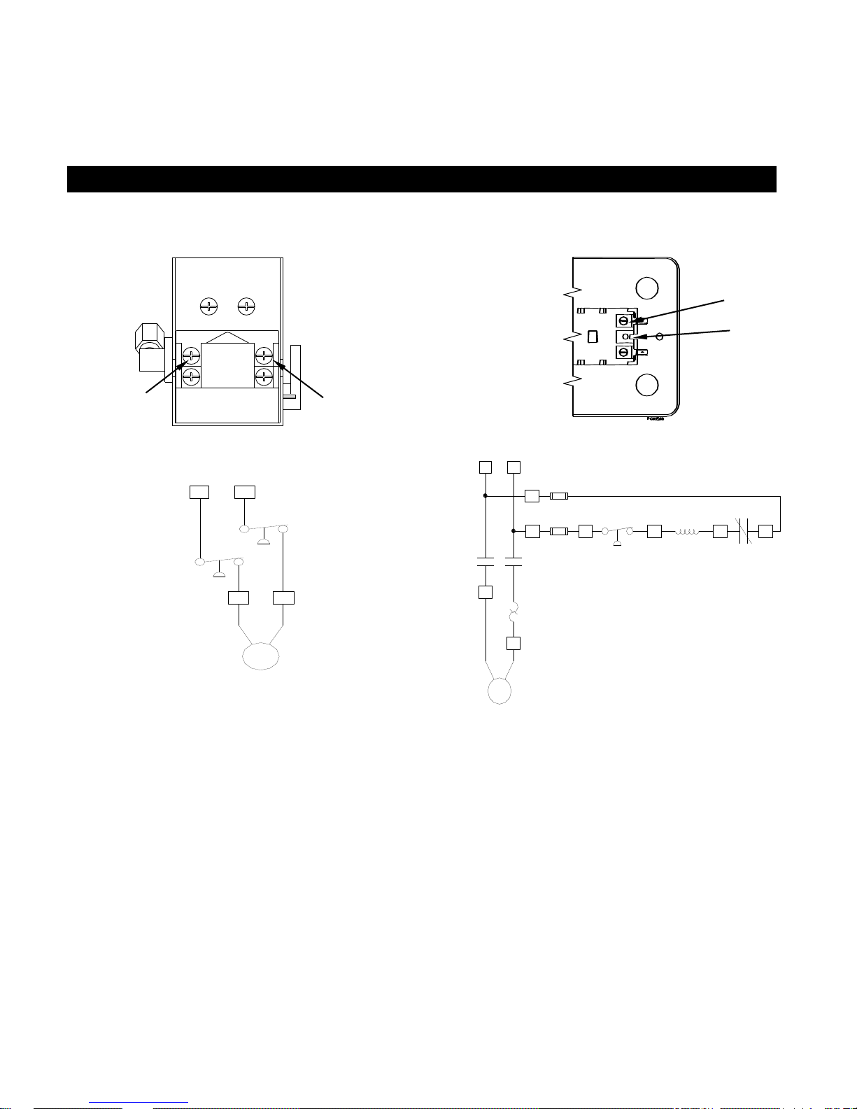
L2
L1
00857
L1
Electrical Service
Customer supplied wires
Pressure
Switch
M
Motor
B1 R1
L2
Pressure
Switch
00865
Motor
Starter
Overload
B1
M
L2
Motor
Starter
Contact
R1
L1
R2
Motor
Starter
Contact
B2
1A
FUSE
B3
R4
Motor
Starter
Coil
R5
Motor
Starter
Overload
R3
Electrical Service
Customer supplied wires
Motor
Pressure
Switch
00865
L2
L1
Condensation Discharge Piping. If installing a
condensation discharge line, the piping must be at
least one size larger than the connection, as short
and direct as possible, secured tightly and routed to
a suitable drain point. Condensation must be
disposed of in accordance with local, state, and
federal laws and regulations.
General. The motor rating, as shown on the motor
nameplate, and the power supply must have
compatible voltage, phase and hertz characteristics.
Wire Size. The electrical wiring between the power
supply and electric motor varies according to motor
horsepower. Power leads must be adequately sized
to protect against excessive voltage drop during
start-up. Information for selecting proper wire size
should be provided by a qualified electrician. If other
electrical equipment is connected to the same circuit,
the total electrical load must be considered in
selecting the proper wire size. Do not use undersized
wire.
NOTE: On units requiring a motor starter, connect
line power to the starter. DO NOT connect the line
power to the pressure switch.
Top View - Pressure Switch
Model 459231
WARNING! If an aftercooler, check valve, block
valve, or any other restriction is added to the
compressor discharge, install a properly sized ASME
approved safety/relief valve between the compressor
discharge and the restriction.
Wiring Installation
Magnetic Starter. If the motor installed on your
compressor has a motor reset button, it does not
require a magnetic starter. If the motor does not
have this button, connect the power leads to the
starter located under the compressor top plate.
Circuit Breaker. Refer to the National Electric
Code to determine the proper circuit breaker rating
required. When selecting a circuit breaker,
remember the momentary starting current of an
electric motor is greater than its full load current.
Time delay or “slow-blow” circuit breakers are
recommended.
WARNING! The installation should be made by a
qualified electrician. If the products must be
reconnected for use on different types of circuits,
the re-connection should be made by qualified
personnel.
Model 459241
Side View - Motor Starter
 Loading...