

Page 1

951XW AND 952XW
GPS C
HART NAVIGATORS
INSTALLATION MANUAL
Northstar Technologies, Inc.
30 Sudbury Road
Acton, Massachusetts 01720
Part number GM1510, Revision B
www.northstargps.com
Service: 978/897-0770
Sales: 978/897-6600
Page 2

Page 3

Limited warranty policy
Northstar Technologies, Inc. warrants the Northstar 951/952 to be free from defects in materials and
workmanship for a period of two (2) years. This warranty applies to the original purchaser and to any
subsequent owner during the warranty period, which begins on the date of shipment of the unit,
F.O.B. Acton, Massachusetts, to an authorized Northstar dealer.
Systems may not be returned to Northstar without a Returned Materials Authorization (RMA) number. Call the Northstar dealer or Northstar for instructions.
During the unit’s warranty period, Northstar will repair or replace, at its option, any part of the unit it
finds to be defective due to faulty material(s) or workmanship. All such repairs and/or replacements
will be promptly performed by Northstar free-of-charge to the owner, excluding freight costs
incurred in shipping to the factory. Return shipments from Northstar to points within the United
States are made via ground transportation, freight prepaid. Special shipping charges (overnight,
two-day, and so on) are the responsibility of the owner.
To be covered by this warranty, the Northstar equipment must have been in normal use. This warranty does not apply to units with defects caused by improper installation, physical damage, abuse,
tampering, lightning or other abnormal electrical discharge, or to units with defaced or altered serial
numbers, or to units repaired by unauthorized persons or repaired in a manner that violates Northstar’s recommended service procedures.
All repairs and/or replacements made under this warranty must be performed at Northstar’s facilities
in Acton, Massachusetts. Performance of warranty work elsewhere will not be authorized, and Northstar will not pay for any charges for such work. Northstar will not be responsible for payment of any
charges imposed by a Northstar dealer or other party for services requested by and/or performed for
a unit’s owner in connection with this warranty. Such services might include removal of the unit
from a vessel, inspection, packaging, handling, reinstallation, and the like.
Northstar Technologies, Inc. assumes no responsibility for any consequential losses of any nature
with respect to any of its products or services sold, rendered, or delivered. The foregoing is the only
warranty expressed or implied. No other warranty exists.
Page 4

Page 5

Table of Contents
SECTION ONE Introduction . . . . . . . . . . . . . . . . . . . . . . . . . . . . . . . . . . . . . . . . . . . . . . . . . . . . . . . . . . . . . .1
Welcome . . . . . . . . . . . . . . . . . . . . . . . . . . . . . . . . . . . . . . . . . . . . . . . . . . . . . . . . . . . . . . . . . . 1
Who should read this manual . . . . . . . . . . . . . . . . . . . . . . . . . . . . . . . . . . . . . . . . . . . . . . . 2
Scope of this manual . . . . . . . . . . . . . . . . . . . . . . . . . . . . . . . . . . . . . . . . . . . . . . . . . . . . . . . 3
Getting technical support . . . . . . . . . . . . . . . . . . . . . . . . . . . . . . . . . . . . . . . . . . . . . . . . . . .3
Servicing the unit . . . . . . . . . . . . . . . . . . . . . . . . . . . . . . . . . . . . . . . . . . . . . . . . . . . . . . . . . . 4
Returning a unit for service . . . . . . . . . . . . . . . . . . . . . . . . . . . . . . . . . . . . . . . . . . . . . . . . . 5
SECTION TWO Installing the unit . . . . . . . . . . . . . . . . . . . . . . . . . . . . . . . . . . . . . . . . . . . . . . . . . . . . . . . .7
Safety considerations . . . . . . . . . . . . . . . . . . . . . . . . . . . . . . . . . . . . . . . . . . . . . . . . . . . . . . . 7
Ordering information . . . . . . . . . . . . . . . . . . . . . . . . . . . . . . . . . . . . . . . . . . . . . . . . . . . . . . . 8
System overview . . . . . . . . . . . . . . . . . . . . . . . . . . . . . . . . . . . . . . . . . . . . . . . . . . . . . . . . . . . 8
Installation considerations . . . . . . . . . . . . . . . . . . . . . . . . . . . . . . . . . . . . . . . . . . . . . . . . . .9
Choosing a system location . . . . . . . . . . . . . . . . . . . . . . . . . . . . . . . . . . . . . . . . . . . . . . . . 11
Wiring the unit . . . . . . . . . . . . . . . . . . . . . . . . . . . . . . . . . . . . . . . . . . . . . . . . . . . . . . . . . . . 16
Installing the antenna . . . . . . . . . . . . . . . . . . . . . . . . . . . . . . . . . . . . . . . . . . . . . . . . . . . . .18
Turning the unit on and off . . . . . . . . . . . . . . . . . . . . . . . . . . . . . . . . . . . . . . . . . . . . . . . . 23
Testing and troubleshooting the 951/952 . . . . . . . . . . . . . . . . . . . . . . . . . . . . . . . . . . . . 27
SECTION THREE Interfacing the unit . . . . . . . . . . . . . . . . . . . . . . . . . . . . . . . . . . . . . . . . . . . . . . . . . . 31
Interfacing the unit . . . . . . . . . . . . . . . . . . . . . . . . . . . . . . . . . . . . . . . . . . . . . . . . . . . . . . . . 31
Configuring the NMEA output ports . . . . . . . . . . . . . . . . . . . . . . . . . . . . . . . . . . . . . . . . . 34
Connecting to other equipment . . . . . . . . . . . . . . . . . . . . . . . . . . . . . . . . . . . . . . . . . . . . . 41
Setting the anchor-watch alarm honk . . . . . . . . . . . . . . . . . . . . . . . . . . . . . . . . . . . . . . . . 49
Configuring the RS-232 port . . . . . . . . . . . . . . . . . . . . . . . . . . . . . . . . . . . . . . . . . . . . . . . . 51
Ordering 951/952 software updates . . . . . . . . . . . . . . . . . . . . . . . . . . . . . . . . . . . . . . . . . 53
APPENDIX A Technical specifications . . . . . . . . . . . . . . . . . . . . . . . . . . . . . . . . . . . . . . . . . . . . . . . . . . 55
951/952 . . . . . . . . . . . . . . . . . . . . . . . . . . . . . . . . . . . . . . . . . . . . . . . . . . . . . . . . . . . . . . . . . . 55
IEC compliance . . . . . . . . . . . . . . . . . . . . . . . . . . . . . . . . . . . . . . . . . . . . . . . . . . . . . . . . . . . 57
Internal WAAS differential receiver specifications . . . . . . . . . . . . . . . . . . . . . . . . . . . . . 57
AN150 Antenna . . . . . . . . . . . . . . . . . . . . . . . . . . . . . . . . . . . . . . . . . . . . . . . . . . . . . . . . . . . 57
951XW/952XW INSTALLATION MANUAL, Revision B Page i
Page 6

Page ii 951XW/952XW INSTALLATION MANUAL, Revision B
Page 7

List of Figures
Figure 1: 951/952 dimensions (side) . . . . . . . . . . . . . . . . . . . . . . . . . . . . . . . . . . . . . . . . . . . . . 12
Figure 2: 951/952 dimensions (front) . . . . . . . . . . . . . . . . . . . . . . . . . . . . . . . . . . . . . . . . . . . . 13
Figure 3: 951/952 yoke mount drilling dimensions . . . . . . . . . . . . . . . . . . . . . . . . . . . . . . . . 14
Figure 4: 951/952 flush mount drilling dimensions . . . . . . . . . . . . . . . . . . . . . . . . . . . . . . . . 15
Figure 5: 951/952 rear connectors . . . . . . . . . . . . . . . . . . . . . . . . . . . . . . . . . . . . . . . . . . . . . . . 17
Figure 6: Separation distances between antennas . . . . . . . . . . . . . . . . . . . . . . . . . . . . . . . . . 19
Figure 7: AN150 antenna dimensions . . . . . . . . . . . . . . . . . . . . . . . . . . . . . . . . . . . . . . . . . . . . 20
Figure 8: Stripping the coax cable jacket . . . . . . . . . . . . . . . . . . . . . . . . . . . . . . . . . . . . . . . . . 21
Figure 9: Flared cable braid . . . . . . . . . . . . . . . . . . . . . . . . . . . . . . . . . . . . . . . . . . . . . . . . . . . . . 21
Figure 10: Completed BNC connector . . . . . . . . . . . . . . . . . . . . . . . . . . . . . . . . . . . . . . . . . . . . 22
Figure 11: Proper insertion of a chart cartridge . . . . . . . . . . . . . . . . . . . . . . . . . . . . . . . . . . . . 24
Figure 12: Interface connector (viewed from back of unit) . . . . . . . . . . . . . . . . . . . . . . . . . . 32
Figure 13: 200 PPNM output . . . . . . . . . . . . . . . . . . . . . . . . . . . . . . . . . . . . . . . . . . . . . . . . . . .34
Figure 14: Cable end connector (wiring side view, solder cup) . . . . . . . . . . . . . . . . . . . . . . 44
Figure 15: Auxiliary port interface diagram . . . . . . . . . . . . . . . . . . . . . . . . . . . . . . . . . . . . . . . 44
Figure 16: Pin 14 honk alarm interface . . . . . . . . . . . . . . . . . . . . . . . . . . . . . . . . . . . . . . . . . . . 49
951XW/952XW INSTALLATION MANUAL, Revision B Page iii
Page 8

Page iv 951XW/952XW INSTALLATION MANUAL, Revision B
Page 9

List of Tables
Table 1: Contacting Northstar . . . . . . . . . . . . . . . . . . . . . . . . . . . . . . . . . . . . . . . . . . . . . . . . . . . 3
Table 2: Troubleshooting the installation . . . . . . . . . . . . . . . . . . . . . . . . . . . . . . . . . . . . . . . . 28
Table 3: Troubleshooting the AN150 antenna installation . . . . . . . . . . . . . . . . . . . . . . . . . 30
Table 4: Interface connector pins . . . . . . . . . . . . . . . . . . . . . . . . . . . . . . . . . . . . . . . . . . . . . . .33
Table 5: Port 1 and 2 setup options . . . . . . . . . . . . . . . . . . . . . . . . . . . . . . . . . . . . . . . . . . . . . 35
Table 6: NMEA 0183 sentence identifiers . . . . . . . . . . . . . . . . . . . . . . . . . . . . . . . . . . . . . . . . 37
Table 7: Connecting to an external Northstar beacon receiver . . . . . . . . . . . . . . . . . . . . . . 45
Table 8: Connecting to Northstar 800 port A . . . . . . . . . . . . . . . . . . . . . . . . . . . . . . . . . . . . . 47
Table 9: Connecting to Northstar 800 port B . . . . . . . . . . . . . . . . . . . . . . . . . . . . . . . . . . . . . 47
Table 10: Northstar 800 series output port setup . . . . . . . . . . . . . . . . . . . . . . . . . . . . . . . . . 47
Table 11: Yeoman plotter setup with the unit . . . . . . . . . . . . . . . . . . . . . . . . . . . . . . . . . . . . 48
Table 12: Beep and honk settings for all alarms . . . . . . . . . . . . . . . . . . . . . . . . . . . . . . . . . . . 51
Table 13: 951/952 specifications . . . . . . . . . . . . . . . . . . . . . . . . . . . . . . . . . . . . . . . . . . . . . . . .55
Table 14: Standards for IEC compliance . . . . . . . . . . . . . . . . . . . . . . . . . . . . . . . . . . . . . . . . . 57
951XW/952XW INSTALLATION MANUAL, Revision B Page v
Page 10

Page vi 951XW/952XW INSTALLATION MANUAL, Revision B
Page 11

SECTION ONE Introduction
Welcome The Northstar 951XW/952XW Installation Manual describes
how to install, interface, and troubleshoot the Northstar
951XW and 952XW GPS chart navigators. Also described are
the physical, mechanical, and electrical characteristics of each
unit. The 952XW features a color display, but is otherwise
identical to the 951XW, except where noted.
For complete details about operating the unit, see the Northstar
951/952 Operator’s Manual (part number GM1500C).
The terms “unit” and “951/952” are used throughout this
manual to refer to both the 951XW and 952XW GPS chart
navigators, which are 951X and 952X navigators (not 951XD or
952XD navigators) that are equipped to receive WAAS satellite
signals. The term “DGPS” is used in this manual to refer to any
differential corrections of GPS signals (WAAS or radiobeacon).
The unit uses a high-performance GPS receiver as its primary
source of position data. Position, COG, and SOG are calculated
directly from the received GPS satellites, along with the time,
the date, and an estimate of the unit’s accuracy.
The 951XW/952XW uses a high-performance GPS receiver as
its primary source of position data. Position, COG, and SOG are
calculated directly from the received GPS satellites, along with
the time, the date, and an estimate of the unit’s accuracy.
Differential corrections to the GPS signals are received from
WAAS (Wide Area Augmentation System) satellites.
951XW/952XW INSTALLATION MANUAL, Revision B Page 1
Page 12

SECTION ONE Introduction
Like Coast Guard radiobeacons, WAAS satellites monitor GPS
signals to determine if errors exist and then provide differential
corrections. The Coast Guard radiobeacon system consists of
nondirectional, short-range beacons installed at lighthouses
and other coastal locations; their range is usually 10 to 175
nautical miles. Radiobeacon differential corrections improve
GPS position fixes to an accuracy of 1 to 3 meters in most cases.
WAAS consists of a network of communication satellites that
are in fixed positions at approximately twice the distance from
the earth’s surface as orbiting GPS satellites. WAAS provides
consistent position accuracy over a greater contiguous
geographic area because it is satellite-based. WAAS differential
corrections maintain a positioning accuracy of less than 3
meters 2dRMS, without the signal interference problems
periodically experienced with low-frequency ground-based
radio-beacon differential signals.
The 951XW/952XW accesses only WAAS signals, not Coast
Guard radiobeacon differential signals, unless it is interfaced to
an external radiobeacon receiver.
Who should read this manual
NOTE:
In the future, Northstar will offer the option of
interfacing the 951/952 to an external
GPS receiver/antenna for receiving GPS (and/or
WAAS) and Coast Guard radiobeacon signals.
You may see references to radiobeacon signals on
some 951/952 screens while following the
installation procedure described in this manual.
However, these references currently apply only if
the unit is interfaced to an external source of
beacon signals that meets the SC104 standard.
You can connect the 951XW or 952XW to an
external source of radiobeacon signals using the
unit’s RS-232 port. For more information about that
option, see ”Configuring the RS-232 port” on page
51.
combined
The Northstar 951XW/952XW Installation Manual is intended
for marine technicians who are configuring and installing
either 951XW or 952XW GPS chart navigators.
Page 2 951XW/952XW INSTALLATION MANUAL, Revision B
Page 13

SECTION ONE Introduction
Scope of this manual
Getting technical support
You can email the
Northstar Service
Department directly from
Northstar’s website. The
address is
www.northstargps.com.
Here, you also can access
additional technical
information under either
the Manuals
can download manuals
in PDF format) or
Support
link (you
link.
In this manual, you’ll find information about the following:
• mounting and wiring the unit
• installing the antenna
• testing and troubleshooting the unit
• configuring the NMEA output ports
• configuring the RS-232 port
• connecting two units to share waypoints and routes
• technical specifications
The rest of this chapter explains how to obtain technical
support and how to return a unit for factory service.
After you’ve followed the instructions in this installation guide,
if you need additional technical support or have any other
service-related questions, you can contact either your dealer or
the Northstar Service Department. You can reach Northstar’s
Service Department by email, fax, U.S. mail, or phone as
described in the table below. Whether you send an email or fax,
or write or phone, please have the unit’s serial number
available, and be as complete and accurate as possible when
describing the problem so that a service technician can
research the problem and provide the quickest possible
response.
Northstar’s Service Department is available between 9:00 a.m
and 5:00 p.m Eastern Time, Monday through Friday, excluding
major holidays.
Table 1: Contacting Northstar
Email:
Service: [email protected]
Sales: [email protected]
Fax:
Service: 978/897-1595
Sales: 978/897-7241
Telephone:
Main number: 978/897-6600 or 800/628-4487
Sales: 978/897-0770
Service: 978/897-6600
951XW/952XW INSTALLATION MANUAL, Revision B Page 3
Page 14
SECTION ONE Introduction
Hearing from you Your feedback is important and helps Northstar ensure that
Table 1: Contacting Northstar (continued)
U.S. mail:
30 Sudbury Road
Acton, MA 01720
Website:
www.northstargps.com (you can send email to
Northstar directly from this site)
this manual is a valuable resource for all marine technicians.
Send your questions, comments, or suggestions about this
manual to:
Servicing the unit Repair of the unit is performed only by authorized Northstar
dealers or at the Northstar factory. Service includes a complete
hardware and software check-out.
NOTE:
For a system under warranty, shipping charges to the factory
are the only cost for factory repair. Repaired units will be
returned via prepaid economy ground freight (units returned
overseas are chargeable).
Units and accessories returned for warranty repair that are
determined to be without fault are subject to a handling
charge.
For units still under warranty, field repairs are not
authorized and will void the warranty!
Page 4 951XW/952XW INSTALLATION MANUAL, Revision B
Page 15

Returning a unit for service
Before returning the unit
to the Northstar factory,
to prevent delays it is
critical that you first
obtain a Return
Materials Authorization
(RMA) number from the
Northstar Service
Department. If you
purchased your unit
through a dealer, call the
dealer with your serial
number so they can give
you an RMA number.
Shipments without a
proper RMA number
will not be accepted!
SECTION ONE Introduction
CAUTION!
The unit is covered by a two-year hardware-only warranty,
which, in summary, states that if the unit is returned to the
Northstar factory by the owner or dealer during the warranty
period, Northstar will repair or replace, free of charge, any part
found to be defective due to faulty materials or workmanship if
the system has been properly installed and hasn’t been abused.
See the Limited Warranty Policy at the front of this manual for
further details. The only cost to the owner will be the one-way
shipping charges and any associated charges that may be
imposed by the dealer. If you have overnight or second-day
shipping requirements, before shipping the unit, please call
Northstar for turnaround time, freight charges, and payment
arrangements.
The unit should be shipped only in a properly designed carton
with packing material. Shipments to the Northstar factory
should be made to the following address:
Before returning the unit for repair, you may want to
back-up any user-defined waypoints and routes;
see the Northstar 951/952 Operator’s Manual (GM
1500C), “Transferring waypoints to and from a PC.”
Northstar Technologies, Inc.
Service Department
30 Sudbury Road
Acton, MA 01720 USA
951XW/952XW INSTALLATION MANUAL, Revision B Page 5
Page 16

SECTION ONE Introduction
Page 6 951XW/952XW INSTALLATION MANUAL, Revision B
Page 17
SECTION TWO Installing the unit
This chapter includes all the information needed to install the
unit. It begins with a review of the system components and
then provides information on unit and antenna installation.
The rest of this chapter describes how to wire the unit, power
the unit on and off, and troubleshoot. Proper installation of the
Northstar 951/952 is of utmost importance to accurately
receive and effectively use GPS and WAAS signals under a wide
variety of weather conditions.
Safety considerations
WARNING!
951XW/952XW INSTALLATION MANUAL, Revision B Page 7
Be sure to turn the power off at the main
switchboard before starting the installation. Further,
it is highly recommended that you post a notice by
this switch telling others to keep power off while
you’re performing the installation. If power is left on
or turned on during the installation, then fire,
electrical shock, or other serious injury may occur.
Be sure to ground the equipment to prevent
electrical shock and mutual interference.
Page 18

SECTION TWO Installing the unit
CAUTION!
CAUTION!
Be sure that the voltage of the power supply is
compatible with the unit’s voltage rating (10-40
volts DC), which can be found on the label at the
rear of the unit. Connecting to the wrong power
supply can result in fire or damage to the
equipment.
Be sure to use the proper fuse. Using the incorrect
fuse can result in fire or damage to the unit.
Keep the following safe compass distance from the
unit: 1.0 m standard, 0.8 m steering.
Be sure that the 951/952 doesn’t interfere with any
of the on-board systems. Check all other systems
to ensure that their performance doesn’t degrade
when the unit is turned on.
Ordering
To order spare parts or replacement/missing parts, call the
Northstar Sales Department at 978-897-0770.
information
System overview The unit is shipped ready to install and operate (however, you’ll
need special tools for assembling the coaxial cable connectors;
see “Mounting the AN150 antenna” on page 20).
It is recommended that you follow the steps below:
1. Check the shipping carton for any damage, and
immediately report any damage to the carrier. Save all
packing material in case you have to return the unit to
the factory for repair or evaluation.
2. Unpack the carton, and compare its contents with those
on the packing list and what you ordered.
The shipping carton contains:
• the Northstar 951XW or 952XW
• yoke-mount kit
• flush-mount gasket
• AN150 GPS and WAAS antenna
• 50-foot coaxial antenna cable
Page 8 951XW/952XW INSTALLATION MANUAL, Revision B
Page 19

SECTION TWO Installing the unit
• 10-foot interface cable
• 10-foot power cable
• flush-mount drilling template (full size)
• connectors and parts kit
• sunshield
• Northstar 951XW/952XW Installation Manual
• Northstar 951/952 Operator’s Manual
• Northstar 951/952 Operator’s Manual Addendum
• warranty card
3. After reviewing the components, next, review the
components of a proper installation. For details, see
”Ensuring a proper installation” on page 10.
4. Select the desired unit mounting location. For details, see
”Choosing a system location” on page 11.
5. Make the appropriate power wiring connections. For
details, see ”Wiring the unit” on page 16.
6. Select the desired antenna mounting location. For details,
see ”Installing the antenna” on page 18.
7. Turn on the unit. For details, see ”Turning the unit on
and off” on page 23.
8. To ensure that the system is running properly, perform a
functional test. For details, see ”Testing and
troubleshooting the 951/952” on page 27.
9. If desired, interface the NMEA output ports; for details,
see ”Configuring the NMEA output ports” on page 34. If
desired, interface the RS-232 port; for details, see
”Configuring the RS-232 port” on page 51.
Installation considerations
CAUTION!
951XW/952XW INSTALLATION MANUAL, Revision B Page 9
The following basic setup information isn’t a
substitute for all the details in SECTION TWO. To
ensure that you meet all critical installation
parameters, be sure to read and follow all of the
requirements.
Page 20

SECTION TWO Installing the unit
Ensuring a proper
installation
To ensure a proper installation, it is highly recommended that
you perform all of the following activities before starting the
installation:
• preview/survey the vessel’s layout and existing
equipment
• review all the installation materials
• review all the installation requirements, including:
■ the physical requirements (spacing, location with
regard to other equipment, etc.)
■ the electrical and electronic requirements (interfer-
ence between other pieces of equipment, power
requirements, etc.)
Although the unit itself is very straightforward and easy to
understand, it has a few basic requirements that must be met
before safe and proper operation can be assured. The major
parts of the rest of this section address several topics regarding
the minimum installation requirements for the unit, to:
• minimize electrical wiring hazards
• accurately receive GPS and WAAS signals
• navigate safely
Pre-installation checkout Northstar recommends you perform a pre-installation checkout
of the unit before installing it on the vessel. This ensures that
the equipment is fully operational, and allows the GPS receiver
to collect its almanac and ephemeris data for the installed
location, which results in less on-board installation time.
Using the AN150 antenna The AN150 antenna is best mounted in the clear, and low on
the vessel to avoid extra motion from pitching and rolling. It
should be mounted lower than directional high-power
transmitting antennas such as radar or satcom. The length of
coaxial cable (supplied with the unit) to the “active” AN150
antenna must be a minimum of 20 feet, but not more than 50
feet. Coil up any unused length of cable; do not cut it to less
than 20 feet! Be sure that all cable connectors are securely
fastened, and that the cable itself isn’t subject to any tight
bends.
For complete details on the AN150, see ”Choosing the antenna
location” on page 18.
Page 10 951XW/952XW INSTALLATION MANUAL, Revision B
Page 21

SECTION TWO Installing the unit
Choosing a system location
The unit houses the receiver for GPS and WAAS signals,
computer, power supply, lights, controls, and specially-coated
display screen.
Before any drilling or cutting takes place, the mounting
location should be chosen carefully: Choose a mounting
location that allows good visibility of the unit’s display screen,
is within comfortable reach, and provides a reasonably direct
path for running the required electrical cabling.
Be sure you have easy access to the control panel’s keys and
that the display can be clearly seen from the normal vantage
point when the user is navigating. Even though the display
screen contains an effective anti-reflective coating, choose a
location that will minimize glare from windows or other bright
objects. Although the unit is direct-sunlight viewable, for
optimal viewing it is recommended that you install the unit in a
location that’s out of direct sunlight.
Although the unit itself is waterproof, the connectors at the
back of the unit aren’t immune to corrosion from saltwater
spray. Protect the unit from prolonged exposure to the
elements by mounting it in a relatively dry area, if possible. At
the end of the day, wipe off the unit with a damp cloth. When
not in use, the unit should be covered with the sunshield to
protect it from excessive heat.
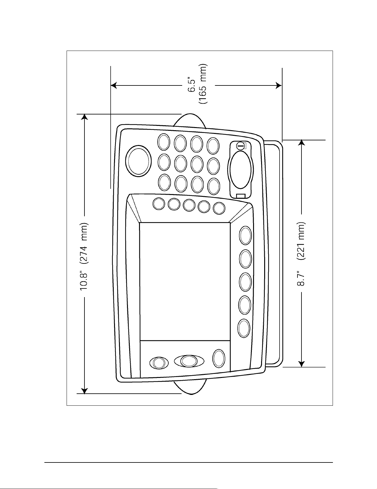
To help plan the installation, see Figure 1: ”951/952 dimensions
(side),” below and Figure 2: ”951/952 dimensions (front),” on
page 13.
951XW/952XW INSTALLATION MANUAL, Revision B Page 11
Page 22

SECTION TWO Installing the unit
Figure 1: 951/952 dimensions (side)
Page 12 951XW/952XW INSTALLATION MANUAL, Revision B
Page 23
SECTION TWO Installing the unit
Figure 2: 951/952 dimensions (front)
951XW/952XW INSTALLATION MANUAL, Revision B Page 13
Page 24
SECTION TWO Installing the unit
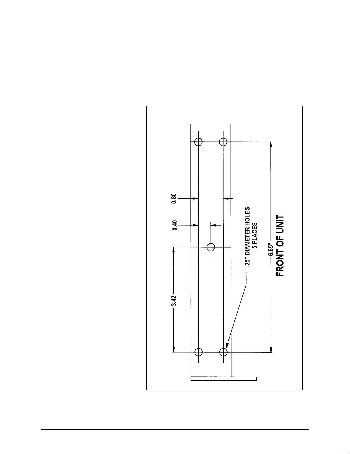
Flush and yoke mounting Whether you’re flush-mounting or yoke-mounting the unit,
allow at least 2½-inches of clearance at the rear for cables and
connectors. For yoke mounting, leave ample room (usually two
inches) all around the sides and top to avoid crowding the unit.
For the recommended yoke mount drilling dimensions, see
Figure 3 below. Before drilling holes, rotate the unit to the
desired angle to ensure proper clearance for cables and
operation of the unit.
Figure 3: 951/952 yoke mount drilling dimensions
Page 14 951XW/952XW INSTALLATION MANUAL, Revision B
Page 25

SECTION TWO Installing the unit
For the recommended flush mount drilling dimensions, see
Figure 4 below. This figure is available in the 951/952 packing
carton as a full-size mounting template (GD670, Rev. B or
higher).
Figure 4: 951/952 flush mount drilling dimensions
951XW/952XW INSTALLATION MANUAL, Revision B Page 15
Page 26
SECTION TWO Installing the unit
CAUTION!
When flush mounting, be sure to mount the unit on
a flat surface. Mounting on a curved surface can
distort or break the plastic and cause a breech in
the waterproof seal. Do not overtighten as case
damage may occur and waterproof integrity may be
compromised. This will void the warranty due to
physical damage.
Wiring the unit The majority of installation problems are caused by shortcuts
taken with system cables. When installing the unit, be sure that
you:
• assemble connectors carefully
• don’t make sharp bends
• leave service and drip loops
• tie-wrap all cables to keep them secure
• if cables are shortened, lengthened, or re-terminated, seal
all wiring splices
The unit should be connected to a source of 10- to 40-volt
electrical power, using at least 16-gauge wire minimum for runs
up to 15 feet. A 10-foot fused power cable is supplied with the
unit, and should be long enough for most installations. If it is
necessary to lengthen the power cable, however, you may
extend it to a maximum of 25 feet (using at least 14-gauge wire
for runs over 15 feet) without adversely affecting the operation
of the unit.
CAUTION!
Ensure that fuse or circuit-breaker protection is
provided at the power source.
Page 16 951XW/952XW INSTALLATION MANUAL, Revision B
Page 27
SECTION TWO Installing the unit
Electrical power
requirements
The unit is a negative-ground system that is reverse-polarity
protected; an external fuse prevents damage to sensitive
components.
The wires in the 10-foot power cable must be connected as
follows (black and white can be connected together at the
power source):
NOTE:
• Red → Positive(+) (fused lead)
• Black → Negative(–)
• White → Ground (earth)
If a noise-free earth grounding point isn’t available,
cap and insulate the white wire. It shouldn’t be used
when an earth ground isn’t available.
Northstar strongly recommends as a good safety practice that
you connect the unit to an external circuit breaker or 3-amp
fuse located near the battery or breaker box. The internal fuse
is designed to protect the unit itself; the external fuse or
breaker is intended to protect the vessel wiring and prevent
electrical fires. Also, for optimum noise immunity, the power
wiring should be connected directly to the battery, when
possible.
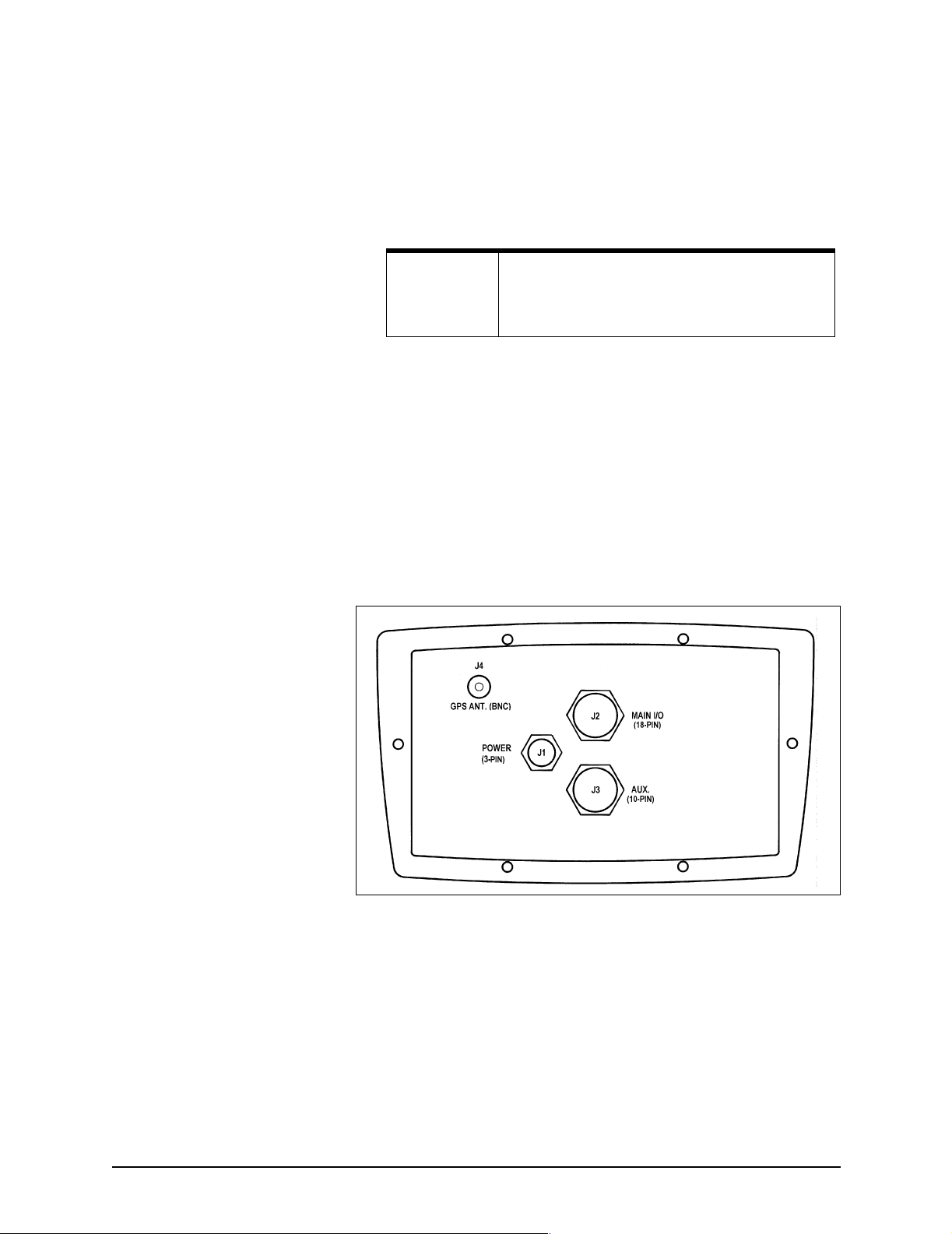
Figure 5: 951/952 rear connectors
• J1 - Power connector (3-pin)
• J2 - Main I/O interface connector (18-pin)
• J3 - Auxiliary (10-pin)
• J4 - AN150 antenna connector (BNC)
951XW/952XW INSTALLATION MANUAL, Revision B Page 17
Page 28

SECTION TWO Installing the unit
Internal fuse The unit is designed with an internal fusible link to protect
against faulty power wiring. The link consists of a short length
of 30 AWG wire located on the I/O circuit board.
Replacement of the fusible link should be performed only by a
qualified electronics technician. If this link becomes
open-circuited between the white and black wires, before
removing the link carefully check all power wiring on the
vessel, especially the white and black wires on the power cable.
You access the link by removing the 10 outer case screws to
open the unit, then removing the four computer-board screws
and lifting the computer board out to expose the I/O board
below. The link should be replaced with another short length
of 30-gauge wire.
Installing the antenna
Choosing the antenna
location
The 951/952 uses a one-piece “active” AN150 antenna for the
reception of GPS and WAAS signals.
The AN150 receiving antenna is a vital link between the unit’s
receiver and the outside world. Aesthetics and easy access
should be secondary to providing strong and reliable GPS and
WAAS signals to the unit’s receiver.
You should select a location for the antenna that meets the
following requirements:
• The antenna should have a reasonably clear view of the
horizon, but be no higher than necessary (side-to-side
motion of the antenna caused by rolling of the vessel
may degrade the SOG and COG readings); however, the
antenna should be 12 to 18 inches above the
surrounding surfaces to avoid interference.
• The antenna must be out of the radiation path of any
on-board radar sets or strong magnetic fields.
• The antenna must be lower than any INMARSAT
communications antenna.
• The antenna should be as far as possible from other
high-power transmitting antennas.
• The length of coaxial cable to the antenna must be
between 20 feet and 50 feet.
• Watch out for electromagnetic “shading” of antennas
from rigging, other vessels, shoreline buildings, and so
on.
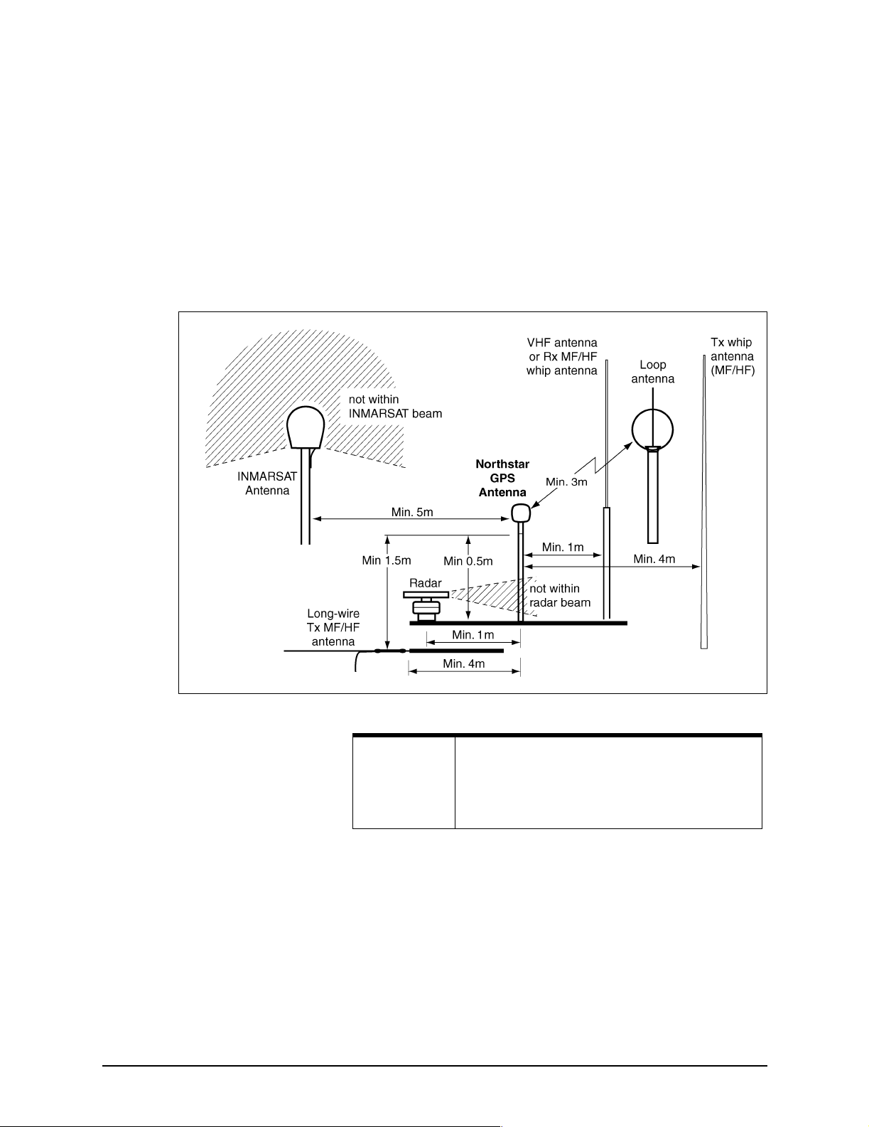
To avoid mutual interferences among different antennas on the
vessel, refer to the recommended separation distances
illustrated in Figure 6: ”Separation distances between
Page 18 951XW/952XW INSTALLATION MANUAL, Revision B
Page 29
SECTION TWO Installing the unit
antennas,” below. This figure shows the minimum
recommended distances for the separation of the AN150
antenna from other antennas and physical mounting surfaces.
Under normal circumstances, following these guidelines
usually results in a relatively trouble-free installation; however,
the installer may want to adjust these distances, depending on
the particular equipment and how it’s configured. Because each
installation is unique—according to the wishes of the
customer—this information should be used only as a guideline.
It isn’t absolute in determining the best location for every
possible equipment configuration.
Figure 6: Separation distances between antennas
NOTE:
Installing the AN150
antenna
951XW/952XW INSTALLATION MANUAL, Revision B Page 19
The AN150 antenna should be mounted as low as possible and
out in the open to avoid “shading” (placement of the antenna
where it’s partially obscured, by another object, from the
signals it must receive). If you’re mounting the antenna on top
of a tower or mast, understand that the unit will be affected by
the pitch and roll of the vessel. Often, the bow or stern can
provide a location where shading is minimized while serving to
keep the antenna low. Be sure that any directional L-band
transmitting antennas (such as radar or satellite
Be especially careful about the distances between
the GPS antenna and any loop-type antenna or
other sources of magnetic interference (for
example, the INMARSAT antenna).
Page 30
SECTION TWO Installing the unit
communication antennas) can never point at the AN150
antenna, since its internal preamplifier is quickly destroyed by
such radiation.
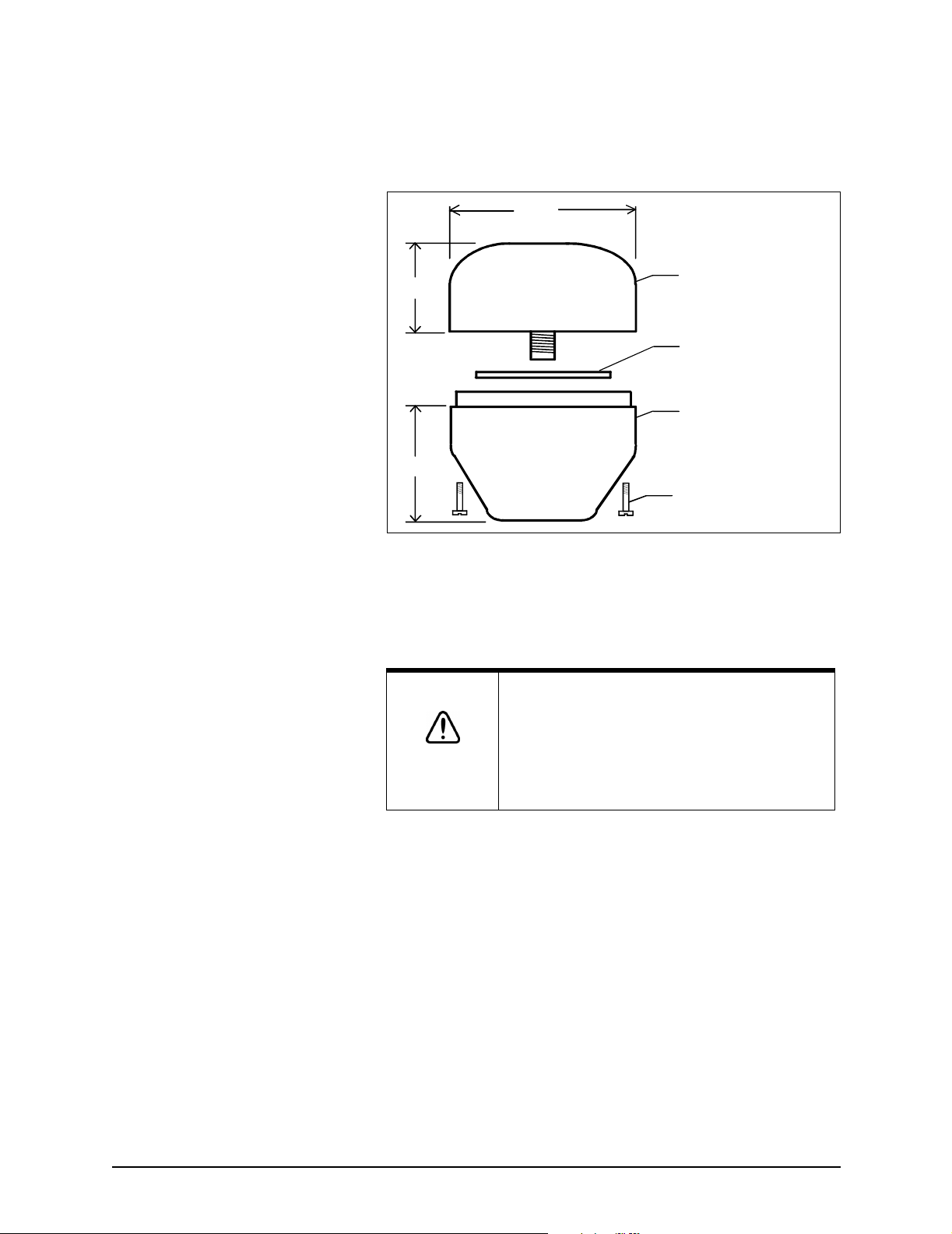
3.00
.91
ANTENNA
O-RING
ADAPTER
1.82
CAPTIVE SCREW
Figure 7: AN150 antenna dimensions
Wiring the AN150 antenna
A 50-foot length of RG-59 coaxial cable is supplied by
Northstar to use with the AN150 antenna.
CAUTION!
The AN150 antenna must be used with a minimum
of 20 feet of cable, and no more than 50 feet. Any
unused length must be coiled up; do not cut it to
less than 20 feet!
Be sure to secure the cable well.
Mounting the AN150 antenna
Tools needed:
• flat-bladed screwdriver
• knife blade
• Amphenol crimp tools
One TNC connector is pre-attached to the antenna-end of the
RG-59 coaxial cable. Connection to the antenna itself involves
the following steps:
1. Remove the antenna base by loosening the four captive
screws in the base.
2. Screw the base onto the top of the antenna mount
(standard 1"-14 marine thread).
Page 20 951XW/952XW INSTALLATION MANUAL, Revision B
Page 31
SECTION TWO Installing the unit
3. Feed the open end of the supplied coax cable down
through the antenna base and through the hollow core
of the antenna mount.
4. Affix the TNC connector-end of the coax to the mating
connector inside the upper half of the antenna. Be sure to
tighten it securely, as vibration can loosen the
connection over time. In addition, protect the
coax-to-antenna connection with liquid electrical tape or
self-vulcanizing electrical tape.
5. Align the upper half of the antenna with the bottom half
and tighten the four screws. Be careful not to overtighten
the screws, as this may deform the watertight seal
between the two antenna halves.
6. Make a termination for a male BNC connection—as
described in the following steps—then connect the
antenna to the female BNC connection at the back of the
unit.
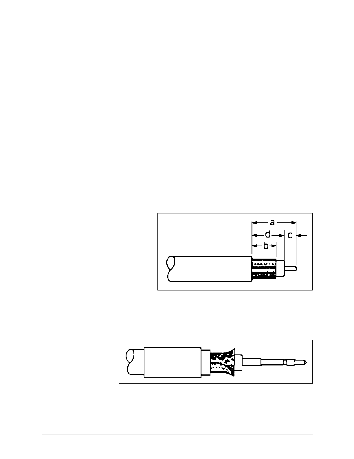
7. Strip cable jacket to the following dimensions (in inches),
as illustrated in Figure 8: ”Stripping the coax cable
jacket,” below: a=0.57, b=0.34, c=0.14, d=0.43. Do not
nick the center conductor.
Figure 8: Stripping the coax cable jacket
8. See Figure 9: ”Flared cable braid,” below: Slide outer
ferrule on as shown. Slightly flare the end of cable braid,
as shown, to facilitate insertion into inner ferrule.
Figure 9: Flared cable braid
951XW/952XW INSTALLATION MANUAL, Revision B Page 21
Page 32
SECTION TWO Installing the unit
9. Place center contact onto center conductor so that it
butts against the cable dielectric. Crimp the contact in
place using Amphenol tool handle #227-944 and Cavity
B of Die Set 227-980-3.
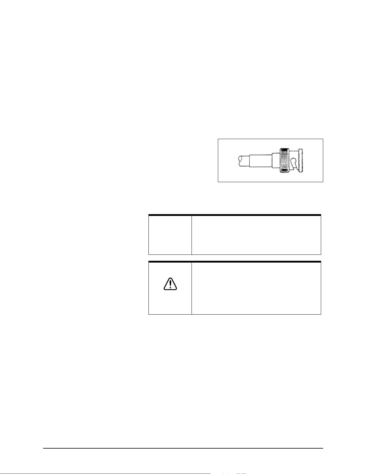
10. Install cable assembly into body assembly so inner
ferrule slides over dielectric and under braid. Push cable
assembly forward until contact seats in insulator. Slide
outer ferrule over braid and up against connector body.
Crimp outer ferrule using Cavity A of tools specified
above. The connector ferrule-to-cable junction can be
sealed and protected using adhesive-lined heat shrink.
Figure 10: Completed BNC connector
NOTE:
WARNING!
Be sure that you properly install the TNC
connector: Most system failures—whether
continuous or intermittent—can be traced to poor
connector installation.
Whenever any antenna is disconnected from
on-board equipment, be sure to ground the
antenna shield in order to discharge static voltages
that can build up on an ungrounded antenna
system. These voltages are hazardous to
personnel and equipment!
Page 22 951XW/952XW INSTALLATION MANUAL, Revision B
Page 33
SECTION TWO Installing the unit
Turning the unit on and off
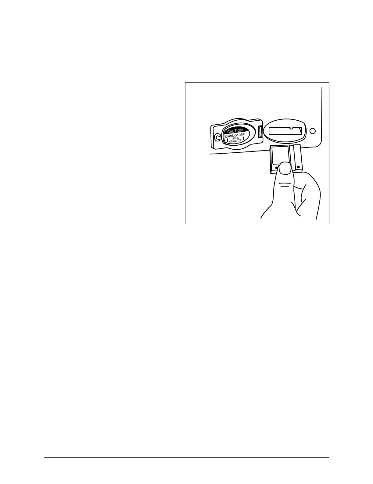
Inserting a chart cartridge If using a chart cartridge, you should insert the cartridge before
turning the unit on to avoid any possibility of a system lock-up.
Before inserting the cartridge, make sure that its label is facing
up and that the cartridge is oriented as shown in Figure 11:
”Proper insertion of a chart cartridge,” on page 24.
The cartridge slot is located at the lower right-hand corner of
the unit. If the unit is off, you can verify whether a cartridge
has already been installed by opening the cartridge access door
(turn its handle ¼-turn counter-clockwise) and looking inside
the slot. If the unit is on, you can verify whether a cartridge has
already been installed by pressing the
key to the right of the
must be fully closed and latched to display this information).
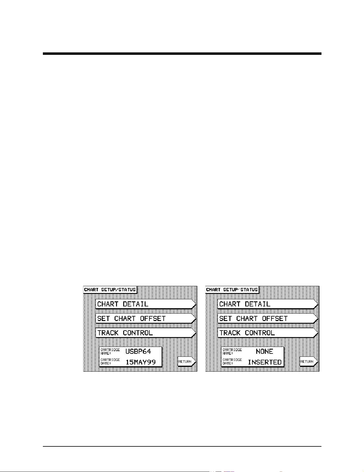
One of two possible screens will be displayed:
CHART screen (the cartridge access door
CHART SETUP menu
• If a cartridge is present, the cartridge name and date are
displayed at the bottom of the
screen (at left below). The cartridge name is derived from
its Navionics catalog number. The date may not be
present for all cartridges, especially older ones; in these
cases, the word
cartridge name and date.
• If a cartridge is either not installed or incorrectly
installed, the words
right below).
PRESENT is displayed in place of the
NONE INSERTED are displayed (at
CHART SETUP/STATUS
951XW/952XW INSTALLATION MANUAL, Revision B Page 23
Page 34
SECTION TWO Installing the unit
The Navionics chart
cartridge must remain
free from debris and
moisture at all times. To
ensure that you do not
expose the cartridge to
any environmental
damage, please use
caution when changing
the cartridge. Exercise
care when inserting the
cartridge into the
Northstar unit (see
description and
illustration at right).
When not in use, store the
cartridge in a clean, dry
place away from heat,
humidity, and dust.
Improper handling and
storage of the cartridge
may result in damage to
the Northstar unit. Such
damage is not covered
under manufacturer
warranty.
Insert the cartridge gently but firmly into position with one
straight, smooth motion. If you partially insert the cartridge,
then move the cartridge again after stopping, it may become
stuck in an awkward position.
Figure 11: Proper insertion of a chart cartridge
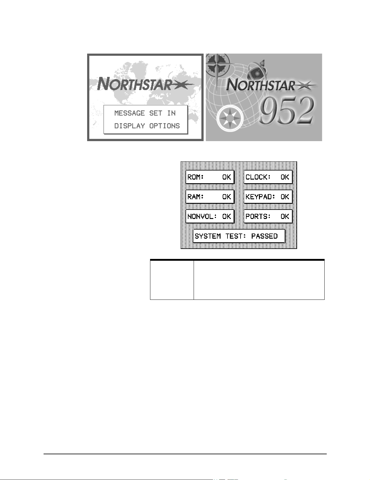
Turning the unit on To activate the unit, briefly press the PWR key. You’ll be
greeted with a map of the Earth with the words
(for the 951XW, at left below) or
952XW, at right below), then the owner identification message.
Next, the unit performs a series of self-tests (the 951 and 952
self-test screens vary slightly) in which critical components and
functions are checked for any errors.
Page 24 951XW/952XW INSTALLATION MANUAL, Revision B
“NORTHSTAR 952” (for the
“NORTHSTAR”
Page 35
SECTION TWO Installing the unit
NOTE:
If the unit’s power has been off and its display
screen is “cold,” a brief warm-up period may be
required for the display screen to achieve its full
intensity.
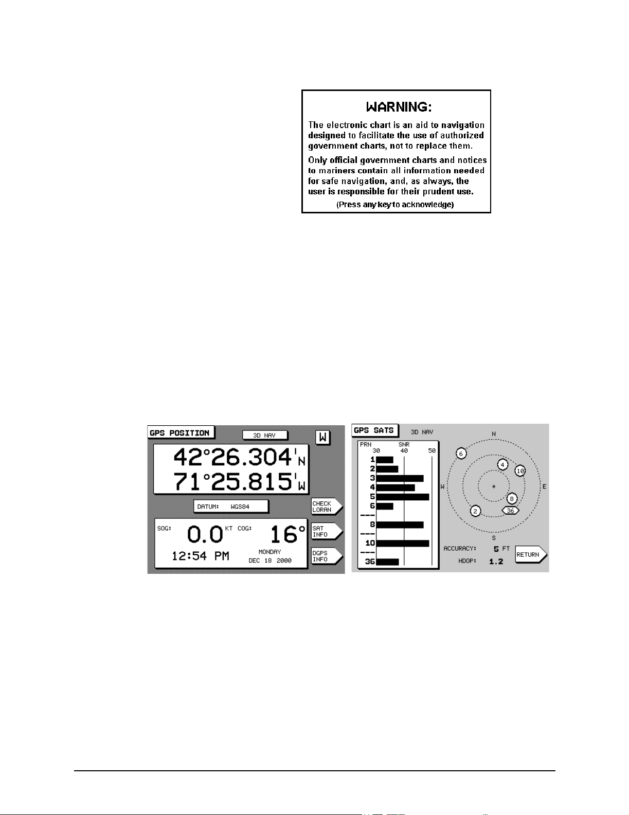
Advisory message When the unit is powered up, a special advisory message is
displayed as a precautionary reminder that the unit’s chart
cartography must not be relied upon as the sole means of safe
navigation. Although every effort has been made to ensure that
the data used by the unit is as close to paper charts as possible,
errors and omissions are inevitable. Therefore, extreme care
must be used when navigating by means of electronic
charts. It is the captain’s responsibility to cross-check the 951/
952 against other sources of navigation data.
To proceed, you must first acknowledge your acceptance of the
advisory message by pressing any one of the five function keys
located beneath the display screen.
951XW/952XW INSTALLATION MANUAL, Revision B Page 25
Page 36
SECTION TWO Installing the unit
Viewing GPS satellite
status
To display more information about signals received from the
GPS satellites, press the
POSITION
indicates that WAAS signals are being received.)
Press the
access the
Signal-to-Noise Ratio (SNR) for each satellite (the higher the
ratio, the better the quality of the satellite signals). Satellites are
identified by their PRN number, a two-digit number assigned
by the U.S. government. On this screen, the satellite map
indicates where the satellites are currently located in the sky.
Circles indicate GPS satellites; hexagons indicate WAAS
satellites.
screen. (The W on the top right corner of the screen
SAT INFO menu key on the GPS POSITION screen to
GPS SATS screen, which shows the received
POSITION key to access the GPS
The center of the satellite map represents the center of the sky,
and the outer (or last) ring is the horizon. The view is looking
down from above, with East to your right and West to your left.
The following GPS data is also displayed:
• ACCURACY: The estimated accuracy--in feet--of the GPS
system to be expected at the current time. Your position
readings should be more accurate than this estimate 95
percent of the time.
• HDOP: This is a technical measure of the quality of your
fix. HDOP (Horizontal Dilution of Precision) is calculated
from the satellites’ current positions, and isn’t based on
Page 26 951XW/952XW INSTALLATION MANUAL, Revision B
Page 37

SECTION TWO Installing the unit
actual received signals. You’ll usually see an HDOP value
displayed immediately after the unit is turned on, and
before it’s ready to navigate. HDOP can range from an
ideal value of slightly less than 1, up to poor values of 10
or more. Any value less than 2 indicates excellent
performance.
Press the
screen.
RETURN menu key to return to the GPS POSITION
Turning the unit off To shut off the unit, press and hold the PWR key for
approximately four seconds until the screen goes dark.
Tes t in g a n d troubleshooting the 951/952
Installation-test checklist To test the system after installation, first apply power to the
unit and confirm power is on with no errors. Next, check for
the presence of GPS and WAAS signals. Review the chart-plotter
function: With the chart cartridge inserted, confirm that the
chart map is displayed.
Troubleshooting common
installation problems
Typical problems you may encounter either during or after the
installation process are outlined in Table 2 below, and in
Table 3, “Troubleshooting the AN150 antenna installation,” on
page 30.
951XW/952XW INSTALLATION MANUAL, Revision B Page 27
Page 38

SECTION TWO Installing the unit
Table 2: Troubleshooting the installation
Problem area Symptom Possible solutions/reasons
POWER Pressing the PWR key doesn’t start
the unit.
DISPLAY The unit powers up, beeps, and the
backlight can be operated up and
down, but there isn’t any video.
The display screen dims, either
slightly or more, after the unit has
been on for a certain time.
SYSTEM
Software-related
system lock-ups
SYSTEM
Hardware-related
system lock-ups
The system locks up under certain
conditions, such as when configuring
screens, routes, waypoints or tide
data.
The system displays the error
message
The system locks up on a random
basis with no apparent pattern.
ROM NO GOOD.
Check the fuse and power to the unit, and
wiring polarity.
If a 951, try adjusting the contrast by pressing
ARROW key. If a 952, the display may
the
have failed (the 952’s
only brightness, not contrast). Call your
Northstar dealer or the Northstar Service
Department.
The unit may be implementing its
auto-dimming mode. Auto-dimming helps
maintain the integrity of the display and reduce
power consumption when the unit is on and
running too hot for its current environment. In
this case, the display screen may dim to half its
intensity.
Install the latest software version; to order, call
the Northstar Service Department.
Install the latest software version; to order, call
the Northstar Service Department.
Internal hardware failure; call your Northstar
dealer or the Northstar Service Department.
ARROW key adjusts
SYSTEM
Configuration
The system locks up when using a
chart card.
The system fails any initial self-tests
other than
No GPS or WAAS.
No WAAS. The system displays the
error message
FAILURE
ROM NO GOOD.
COMMUNICATION
.
Possible bad chart card. Remove the card, and
inspect the pin area of the card and the unit for
damage. If the pins in the unit are bent or
damaged, to prevent further damage, don’t
insert another card. If you’re sure that the card
pins aren’t bent, try inserting a new card.
Internal hardware failure; call your Northstar
dealer or the Northstar Service Department.
For verification and troubleshooting of the
antenna system, see Table 3,
“Troubleshooting the AN150 antenna
installation,” on page 30.
The 951/952 is not communicating properly
with its internal GPS (or WAAS) engines. This
may be an internal hardware failure; call your
dealer or the Northstar Service Department.
Page 28 951XW/952XW INSTALLATION MANUAL, Revision B
Page 39

SECTION TWO Installing the unit
Table 2: Troubleshooting the installation (continued)
Problem area Symptom Possible solutions/reasons
CHART CARDS System freezes when using a
particular chart cartridge at a
particular resolution.
Chart is missing the proper detail at a
particular resolution (zooming in or
out solves the problem).
System lock-up.
INTERFERENCE Electrical, magnetic, or radio
frequency (RF) energy is interfering
with the reliable operation of the unit,
as shown by high levels of noise on
DGPS STATUS screen.
the
GPS The unit powers up, but poor GPS
SNR readings are obtained, even
after running the unit for several
minutes.
Possible bad chart cartridge; call your
Northstar dealer for a replacement.
Possible bad chart cartridge; call your
Northstar dealer for a replacement.
Inserting a chart cartridge before turning the
unit on may cause a lockup; turn off the unit
and turn it back on (with the chart cartridge
already inserted).
Turn off power to each and all of the vessel’s
other instruments and systems, one at a time,
to isolate the source of the interference.
Attempt to eliminate the noise through earth
grounding or RF filtering techniques as
appropriate to the type of noise encountered.
Check that you have the proper length and
type of cable, and that all connections are
clean and secure.
Verify the quality of the antenna location (the
antenna should have a clear view of the sky).
For the correct antenna placement, see
Figure 6 on page 19.
DGPS, if an
external source of
radiobeacon
signals is
connected to the
unit
Low beacon SNR or low signal
When vessel interference is still
present
Troubleshooting common
GPS antenna installation
problems
See Table 3 on page 30.
Turn off all electrical devices and equipment
on the vessel, then check for improvement.
Check fluorescent lights, gauges, and so forth.
Be creative! Check for power-line interference
by moving away from the dock and/or marina.
Isolate to the interfering device, with breaker
panel if necessary, or by physical
disconnection, if required.
Whenever possible, the best and most efficient way to
troubleshoot is to use a known-good set of cables and working
antennas as spares for swapping.
951XW/952XW INSTALLATION MANUAL, Revision B Page 29
Page 40
SECTION TWO Installing the unit
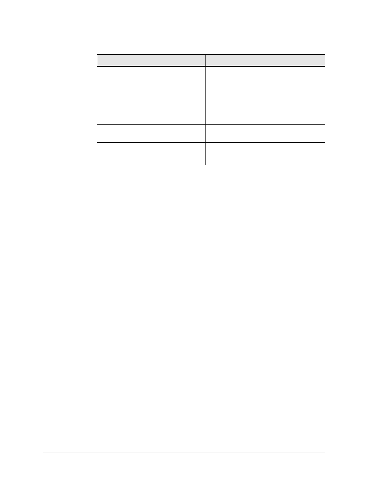
Table 3: Troubleshooting the AN150 antenna installation
Symptom Possible Solutions/Reasons
Poor or no GPS signal while using the
AN150 12-dB GPS antenna.
5.5 VDC low or missing with load
connected
5.5 VDC is missing with load disconnected It indicates a bad GPS board.
5.5 VDC is present It indicates a bad AN150. Replace the AN150.
Turn off any onboard transmitting devices.
Check for 5.5 VDC at antenna with and without
antenna load connected. The GPS receiver
supplies the 5.5 VDC to the AN150 active GPS
antenna.
Check for 5.5 VDC at 951/952 BNC connector.
It indicates a bad connector installation, bad
GPS board, or bad AN150 antenna.
Page 30 951XW/952XW INSTALLATION MANUAL, Revision B
Page 41

SECTION THREE Interfacing the unit
This chapter includes the information needed to interface the
951/952 to other equipment on the vessel. Major topics
include:
• interfacing the unit
• connecting the unit to other equipment
• connecting the unit to other 951s, 952s, and 941s in
order to transfer all waypoints and routes
• configuring the NMEA output ports
• configuring the RS-232 port
• uploading software
Interfacing the unit
951XW/952XW INSTALLATION MANUAL, Revision B Page 31
The unit is easily interfaced to other equipment as described
below. The most common interface data format used with
installations today is NMEA 0183, which is a widely accepted
standard of data transfer between almost all types of marine
electronics, enabling completely different instruments to
“speak” a common language.
The unit has the following ports:
• two programmable NMEA input/output ports
• one RS-232 input/output port that you can customize for
communicating data to or from other instruments
Page 42
SECTION THREE Interfacing the unit
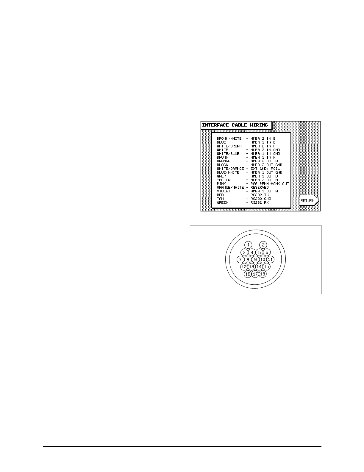
Connector pin wiring A list of wire designations for the interface connector is
displayed on the unit’s
INTERFACE CABLE WIRING screen.
1. Press the
CUSTOMIZATION
2. Press the PORT SETUP OPTIONS menu key to display
the
3. Press the WIRING INFO menu key. The unit displays the
interface cable wiring list, as shown below
STAR key until you see the USER
screen.
PORT SETUP OPTIONS screen.
Figure 12: Interface connector (viewed from back of unit)
Page 32 951XW/952XW INSTALLATION MANUAL, Revision B
Page 43

SECTION THREE Interfacing the unit
Table 4: Interface connector pins
Description Wire color Pin
NMEA PORT 1 INPUT A BROWN 3
NMEA PORT 1 INPUT B BLUE 1
NMEA PORT 1 INPUT
GROUND
NMEA PORT 1 OUTPUT A VIOLET 12
NMEA PORT 1 OUTPUT B GRAY 7
NMEA PORT 1 OUTPUT
GND
NMEA PORT 2 INPUT A WHITE w/BROWN STRIPE 6
NMEA PORT 2 INPUT B BROWN w/WHITE STRIPE 2
NMEA PORT 2 INPUT
GROUND
NMEA PORT 2 OUTPUT A YELLOW 15
NMEA PORT 2 OUTPUT B ORANGE 11
NMEA PORT 2 OUTPUT
GND
RS-232 GROUND TAN 17
RS-232 RX GREEN 16
RS-232 TX RED 18
WHITE w/BLUE STRIPE 4
BLUE w/WHITE STRIPE 8
WHITE 5
BLACK 10
EXT. GND / FOIL DRAIN WHITE/ORANGE & SHIELD 9
RESERVED ORANGE w/WHITE STRIPE 13
200 PPNM/HONK OUT
(Pulses Per Nautical Mile)
PINK 14
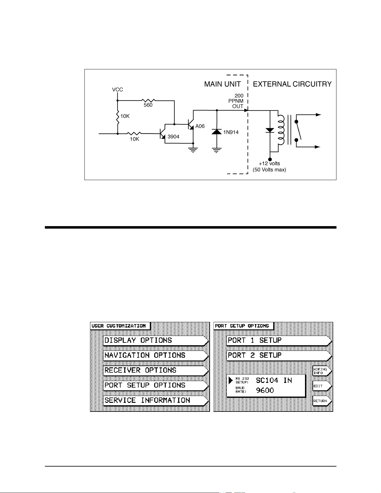
200 ppnm output The unit provides an open-collector transistor output (on pin
14) that’s programmed to produce 200 pulses per nautical mile
for those devices requiring this output.
The emitter of the NPN transistor is connected to ground, and
the collector connects to the output pin side (see Figure 13:
”200 PPNM output,” on page 34). The output can sink 100mA,
and can withstand a maximum positive voltage of 50 volts.
If the output connects to a highly inductive device (for
example, a relay), a spike suppression diode such as a 1N4001
should be connected across the load. Cathode connects to the
power side of the device and anode connects to the output pin
side.
951XW/952XW INSTALLATION MANUAL, Revision B Page 33
Page 44
SECTION THREE Interfacing the unit
The output produces a negative pulse 80ms wide and supports
speeds from zero to 100 knots (clamps at 100kt).
Figure 13: 200 PPNM output
Configuring the NMEA output ports
Each output port can be programmed to meet most any special
requirements of devices that conform to the NMEA 0183—and
other—data format specifications. The
described below allows the selection of the specific 0183
sentences that the 951/952 will transmit.
1. Press the
CUSTOMIZATION
2. Press the PORT SETUP OPTIONS menu key to display
the
STAR key until you see the USER
screen.
PORT SETUP OPTIONS screen.
SETUP function
Page 34 951XW/952XW INSTALLATION MANUAL, Revision B
Page 45
SECTION THREE Interfacing the unit
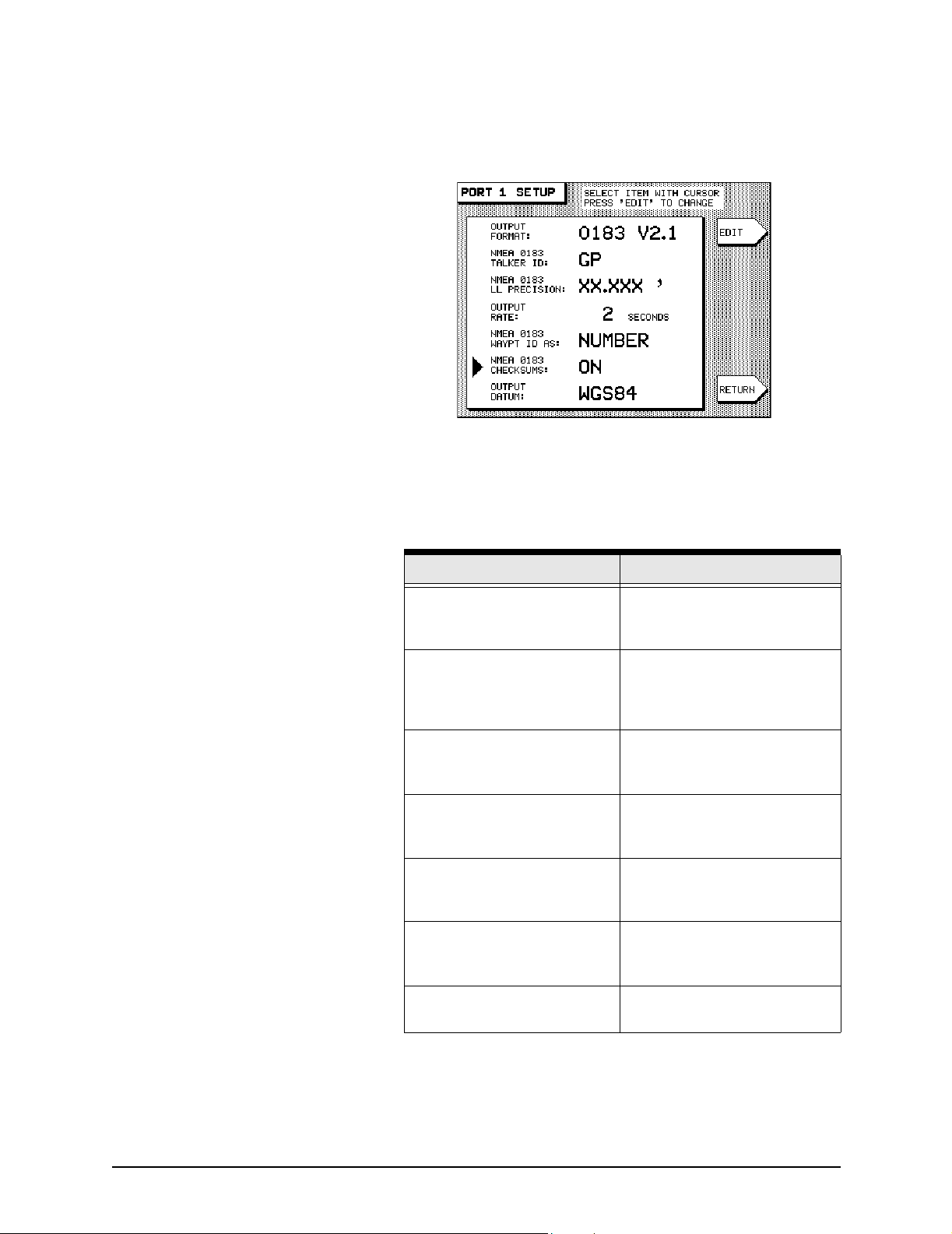
3. Press the PORT 1 SETUP or PORT 2 SETUP menu key.
On either screen, the unit displays a list of data format
control options, as shown below.
Check the installation instructions of the equipment to which
you’re interfacing for any special requirements. The Northstar
factory settings are adequate for most peripheral equipment,
but the following options are available, if needed:
Table 5: Port 1 and 2 setup options
Parameter Options
OUTPUT FORMAT
(see below)
NMEA 0183 TALKER ID
(see page 38)
NMEA 0183 LL PRECISION
(see page 39)
OUTPUT RATE
(see page 39)
NMEA 0183 WAYPOINT ID AS
(see page 40)
NMEA 0183 CHECKSUMS
(see page 40)
choose NMEA 0180, NMEA
0183 V2.0, 0183 V1.5, RAY
0183, DATAM CDX, or NONE
choose GP, LC, or II, to make
the unit look like a GPS receiver,
Loran-C receiver, or an
“integrated instrument”
choose hundredths of minutes,
thousandths of minutes, or
ten-thousandths of minutes
choose 2 to 999 seconds for the
interval at which data is sent to
the external device
choose NAME or NUMBER for
the identifier of waypoints sent to
the external device
choose ON or OFF for
compatibility with some older
devices
OUTPUT DATUM
(see page 41)
951XW/952XW INSTALLATION MANUAL, Revision B Page 35
choose from a list of datums to
apply to your lat/lon coordinates
Page 46
SECTION THREE Interfacing the unit
Setting the output format The unit outputs navigation data in any of several standard
formats as required by the receiving, or “listener,” device.
Highlight the
menu key and the
choices available:
0183 RAY
• NMEA 0180 is an infrequently used format, developed in
the late 1970’s, required by certain older autopilots.
• NMEA 0183 VERSION 2.1 is a general-use interface
output format used by most autopilots, radars, plotters,
and other equipment. The NMEA 0183 Version 1.5
sentences (BWC, GLL, and RNN) enable the 952X to be
backward-compatible with marine equipment previously
designed for this earlier version of 0183. For details on
using the 0183 format, see ”About NMEA 0183 and RAY
0183” on page 36.
• DATAMARINE CDX is required by Datamarine’s
cross-track-error indicators, the latest of which display
distance and bearing to the waypoint.
• 0183 RAY is used when transmitting/receiving position
information to or from Raytheon equipment. It uses
Raytheon’s non-standard NMEA 0183 checksum, where,
on output, the checksum isn’t included, and on input to
the 951/952, the checksum is ignored. Format is
supported on Port 1 and Port 2.
OUTPUT FORMAT option, then press the EDIT
CURSOR PAD, and you’ll find the following
NMEA 0180, 0183 V2.1, DATAMARINE CDX,
and NONE.
About NMEA 0183 and
RAY 0183
NOTE:
• The NONE setting is used when the unit isn’t connected
to an external device.
NMEA 0183 enables GPS and loran navigators, for example, to
“talk” to plotters, radars, charting instruments, and other
electronics, by means of a common language.
With the checksum ignored on input, it is possible
that the unit may receive contaminated NMEA data
when connected to an external Raytheon loran.
Displaying NMEA output sentences
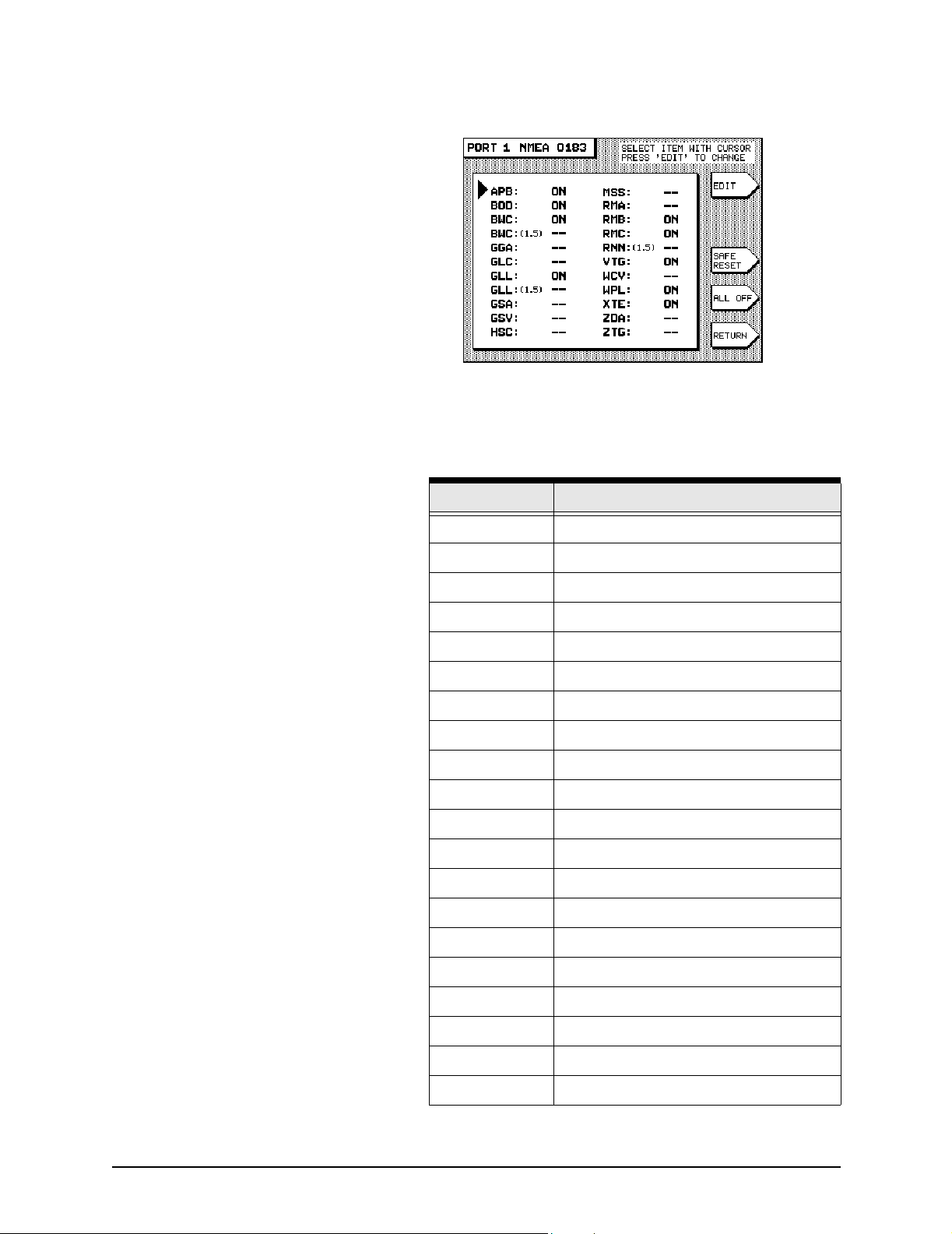
When you select NMEA 0183 or RAY 0183 as the output format
(after pressing the
is displayed showing all the available NMEA 0183 sentences
that the 951/952 can output.
EDIT menu key) and press ENTER, a screen
Page 36 951XW/952XW INSTALLATION MANUAL, Revision B
Page 47
SECTION THREE Interfacing the unit
Three-letter abbreviations identify each sentence and are listed
alphabetically. The meanings of the NMEA 0183 three-letter
identifiers are defined in the table below.
Table 6: NMEA 0183 sentence identifiers
0183 identifier Meaning
APB Autopilot Sentence “B”
BOD Bearing to Destination
BWC Bearing & Distance to Wpt. (Great Circle)
GGA GPS Fix Data
GLC Geographic Position, Loran-C
GLL Latitude/Longitude
GSA GPS DOP and Active Satellites
GSV GPS Satellites In View
HSC Heading Steering Command
MSS MSK Receiver Signal Status
RMA Recommended Min. Sentence A
RMB Recommended Min. Sentence B
RMC Recom. Min. Specific GPS/Transit Data
RNN Navigation Route
VTG SOG/COG
WCV Waypoint Closure Velocity (SOA)
WPL Waypoint Location
XTE Cross-track Error
ZDA Estimated Time of Arrival
ZTG Time-To-Go
951XW/952XW INSTALLATION MANUAL, Revision B Page 37
Page 48

SECTION THREE Interfacing the unit
The sentences that will be output are followed by the word ON,
those that won’t be output are followed by two dashes to
and
signify that they’re turned off. Some devices can’t handle all
these sentences correctly, so you can use this screen to
customize the output by turning individual sentences to the
ON or DASHES (off) setting. In general, you may want to turn
on only those sentences used by the particular equipment to
which you’re interfacing the 951/952.
Turning NMEA output sentences on and off
To turn on or off the unit’s NMEA 0183 sentences, first follow
the above description to display the
then perform the following steps:
0183 SENTENCE screen,
Choosing the NMEA 0183
talker ID
1. Press the
want to turn on or off, then press the
2. Press the CURSOR PAD to toggle the sentence on or off,
and press
leave it unchanged).
3. Repeat for each sentence as desired. When you’re done,
press the
SETUP
If you want to set all the sentences to the factory settings for
recommended output, press the SAFE RESET menu key.
If you want to turn on only a select few sentences for output,
press the
turn the desired ones back on.
Part of the NMEA 0183 standard requires that the equipment
you’re interfaced to—the “listener”—knows what type of device
is transmitting the data. The talker ID tells the listener that it is
receiving information from a navigation source (the 951/952),
not a communications or sensor device, which transmits
completely different and therefore unusable forms of data.
The talker ID enables you to configure the unit’s output data to
tell the listener it’s receiving data from a loran (
navigator, or Integrated Instrument (
depends on what the listener device is expecting.
CURSOR PAD to highlight the sentence you
EDIT menu key.
ENTER to make your selection (or CLEAR to
RETURN menu key to go back to the PORT
screen.
ALL OFF menu key to turn off all sentences, then
LC) or GPS (GP)
II). The choice you make
1. Check the listener device’s instruction manual to
determine which “talker ID” codes it will respond to.
2. At the
CURSOR PAD to highlight the NMEA 0183 TALKER ID
option, then press the
3. Scroll through the three choices using the CURSOR PAD
to make your selection, and press the
done.
The interfaced equipment will now receive the 0183 data in the
correct nav-source format.
Page 38 951XW/952XW INSTALLATION MANUAL, Revision B
PORT 1 SETUP or PORT 2 SETUP screen, press the
EDIT menu key.
ENTER key when
Page 49

SECTION THREE Interfacing the unit
Setting NMEA 0183 lat/lon
precision
For added versatility in communicating with a variety of other
devices, you can control the level of precision of the 0183
position information as it is output by the 951/952. The choice
you make depends on the equipment to which you’re
outputting NMEA data. For the number of digits of precision
required for that particular device, refer to the manufacturer’s
instructions.
• XX.XX ’ (lat/lon precision to two decimal places/
hundredths of minutes/or 60 feet)
• XX.XXX ’ (lat/lon precision to three decimal places/
thousandths of minutes/or 6 feet; this is the factory
setting)
• XX.XXXX ’ (lat/lon precision to four decimal places/
ten-thousands of minutes/or roughly ½ foot)
The 951/952 conforms to the NMEA version 2.00 standard, and
is also compatible with version 1.50. Equipment typically
benefiting the most from three and four decimal places of
precision are electronic and pen plotting devices. However,
most older devices designed to operate with the original 0183
and other formats can only function with two-place precision.
1. At the
the
PORT 1 SETUP or PORT 2 SETUP screen, highlight
NMEA 0183 LL PRECISION option, then press the
EDIT menu key.
2. Scroll through the three choices using the CURSOR PAD
to make your selection, and press the
ENTER key when
done.
NOTE:
Setting the output precision to three or four decimal
places doesn’t mean that the 951/952 will navigate
with that accuracy. Position information can be
output and displayed to four decimal places, but the
user’s ability to actually navigate with such
accuracy is limited by the accuracy of the Loran
and GPS systems (see the Northstar 951/952
Operator’s Manual). Therefore, specifying more
decimal places in the data output doesn’t
necessarily result in greater navigating accuracy.
Changing the output rate The unit lets you use a one-second update interval, a rate of 1
Hz, under limited circumstances, for NMEA and diagnostic data
output. Using the 1-Hz output option requires some thought
when specifying either NMEA 0183 (NMEA version 2.0) or
Raytheon (RAY 0183). Because there isn’t enough time to
transmit all available sentences within one second, you must
select for output only those that are needed. If you select more
sentences than can be output in one second, the unit displays
the following error message:
951XW/952XW INSTALLATION MANUAL, Revision B Page 39
Page 50
SECTION THREE Interfacing the unit
SORRY, CAN’T DO THAT. TOO MANY SENTENCES FOR 1 SEC
INTERVAL
If this message is displayed, you must select fewer sentences.
There are some applications that require a longer update
period. In that case, the unit allows you to increase that span to
999 seconds.
1. At the
PORT 1 SETUP or PORT 2 SETUP screen, press the
CURSOR PAD to highlight the OUTPUT RATE option,
then press the
EDIT menu key.
2. Enter your numerical selection, and press the ENTER key
when done.
Changing the NMEA 0183
waypoint ID
Many marine electronic devices (such as radars and electronic
plotters) can display the waypoint names, if they’re output by
the 951/952.
1. At the
PORT 1 SETUP or PORT 2 SETUP screen, press the
CURSOR PAD to highlight the NMEA 0183 WAYPOINT ID
option, then press the EDIT menu key.
AS
2. Change the option from NUMBER to NAME, and press
ENTER key when done. The listening device will now
the
display the six-character waypoint names.
NOTE:
NOTE:
Be sure to verify this capability in the listening
device before changing the
ID AS
understand this identifier, and using it may cause
problems with the display of the waypoint
information.
There is no standard for identifying how numbers
should be assigned when converting waypoints
from names to numbers. When you export
waypoint information as numbers to a peripheral
device, be aware that numbers aren’t sequentially
defined and may be re-used on a random basis.
option. Most older equipment won’t
NMEA WAYPOINT
Setting the NMEA 0183
checksum
Certain older devices may not accept sentences containing the
NMEA 0183 checksum that’s output by the 951 or 952. In such
cases, the device may not operate properly, if at all. If you
encounter difficulty when interfacing to older equipment, the
unit offers the flexibility of turning off the NMEA 0183
checksum.
1. At the
PORT 1 SETUP or PORT 2 SETUP screen, press the
CURSOR PAD to highlight the NMEA 0183 CHECKSUMS
option, then press the
Page 40 951XW/952XW INSTALLATION MANUAL, Revision B
EDIT menu key.
Page 51

SECTION THREE Interfacing the unit
2. Press the CURSOR PAD to change the setting from ON to
OFF, and press the ENTER key when done.
Selecting an independent
NMEA output-port datum
Connecting to other equipment
Connecting to other
Northstar units
You can adjust output position for NMEA 0183 ports 1 and 2 to
specific geodetic datums, independently of the datum you
choose for positional display.
1. At the
the
key.
2. Scroll through the choices using the
to make your selection. To apply this chosen datum to
your lat/lon coordinates in the NMEA 0183 output
sentences, press the
Two 951, 952, or 941 units can be connected in order to take
advantage of the waypoints/routes sharing feature. This
convenient feature lets all waypoints and routes be transferred
between any combination of two of these units.
PORT SETUP 1 or PORT SETUP 2 screen, highlight
OUTPUT DATUM option, then press the EDIT menu
CURSOR PAD down
ENTER key.
Using this feature involves three main steps, which you should
perform in the following order:
1. Check that each unit you want to share waypoints and
routes with is operating with software version 3.12 (or
higher). To determine the units’ current software version,
press the
CUSTOMIZATION
INFORMATION
INFORMATION
displays the current software version. If this version is
earlier than 3.12, you must upgrade this unit to version
3.12 (or higher) before it can share waypoints and routes
with another unit. To obtain software version 3.12 (or
higher), call the Northstar Sales Department to order the
Waypoint Database Sharing Upgrade Kit, part number
1500-WDS, which includes step-by-step instructions for
installing the software.
2. Connect two units to allow for transferring of all
waypoints and routes (call the Northstar Sales
Department to order the connector kit, part number
1500-WDS).
STAR key until you display the USER
screen is, then press the SERVICE
key to display the SERVICE
screen. The MAIN BOARD SOF VER field
951XW/952XW INSTALLATION MANUAL, Revision B Page 41
Page 52
SECTION THREE Interfacing the unit
3. Transfer all waypoints and routes between the desired
units.
NOTE:
NOTE:
When transferring waypoints and routes between
two units, Northstar recommends that you follow
the detailed instructions in the Northstar 951/952
Operator’s Manual (GM1500C, Revision B or
higher). Failure to follow these instructions may
result in the loss of valuable waypoint and route
data. It is highly recommended that you read these
instructions before transferring waypoints and
routes.
Remember: Every unit you want to import
waypoints and routes to, or export waypoints and
routes from, must have the waypoint/route sharing
software upgrade (version 3.12 or higher) installed.
You can’t import waypoints/routes into a unit, or
export waypoints/routes from a unit, that doesn’t
have the waypoint/route sharing feature, regardless
of whether the other unit has the feature.
Connecting the two units
Before you can transfer waypoints and routes between the two
units, they must be properly connected using the following
parts from the Waypoint Database Sharing Upgrade Kit:
• 2 backshells with cable clamps (2), screws (4), and o-rings
(2)
• 2 solder-cup-style cable connectors
• 2 twist lock rings
• 3 different-size rubber strain relief grommets (6 total, 2 of
each size, for different size cables)
You must supply a cable: Use only Belden #9502 twisted pair
cable or approved equivalent.
Connecting the units involves three main steps: assembling the
cable that connects the two units, terminating both ends of the
cable, and connecting both ends of the cable to the units’ 10-in
connectors. These are described below.
Page 42 951XW/952XW INSTALLATION MANUAL, Revision B
Page 53

SECTION THREE Interfacing the unit
To assemble the cable:
1. Cut the cable to the desired length.
2. Slide the following parts onto each end of the cable, in
the following order:
• connector backshell
• rubber-strain relief grommet (using the appropriate
size) that fits inside the backshell
• twist lock ring (also known as a quarter turn), ensuring
that it’s facing in the correct direction.
3. Trim and prepare the wires for soldering to the connector
body.
4. Terminate the cable, as described below.
To terminate the cable:
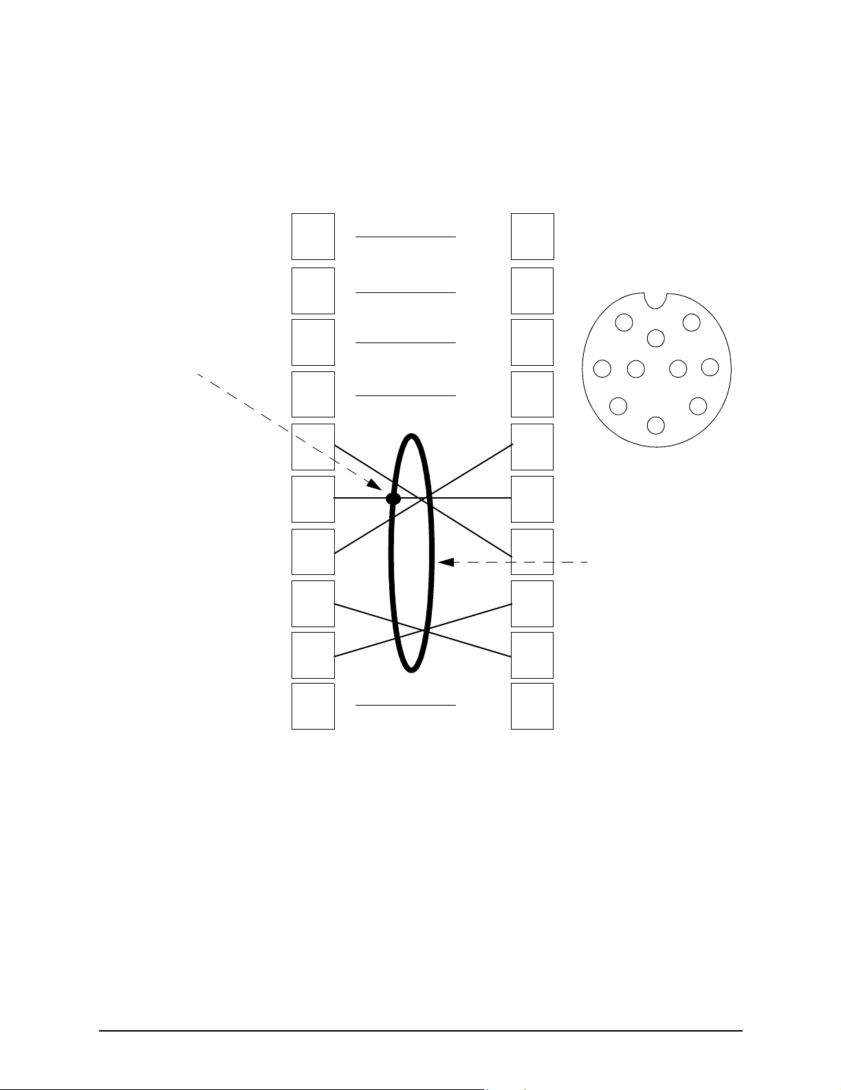
1. Terminate and solder the appropriate wires to the
appropriate pins. See Figure 15: ”Auxiliary port interface
diagram,” below.
951XW/952XW INSTALLATION MANUAL, Revision B Page 43
Page 54
SECTION THREE Interfacing the unit
Shield
termination
Aux input A
Ground/shield
Aux output A
CONNECTOR A
(connects to unit auxiliary port)
Pin number
1
No connect
2
No connect
3
No connect
4
No connect
5
6
7
CONNECTOR B
(connects to unit auxiliary port)
Pin number
1
2
3
4
1
3
5
4
8
6
10
5
Figure 14: Cable end
6
7
connector (wiring side
view, solder cup)
Shield
2
7
9
Aux input B
Aux output B
8
9
10
No connect
8
9
10
Figure 15: Auxiliary port interface diagram
2. Slide the twist lock onto the connector body.
3. Screw the connector backshell to the connector body,
and tighten.
4. Install the strain-relief clamp with two screws.
5. Connect both cable ends to a 941/951/952, as described
below.
To connect the cable ends:
1. Plug each end of the cable into the 10-pin ports at the
back of each unit.
Page 44 951XW/952XW INSTALLATION MANUAL, Revision B
Page 55
SECTION THREE Interfacing the unit
2. Turn both units on.
3. Test for the proper cable connection: Press the WAYPTS/
ROUTES
then the
menu key; then the
should read
key; then the IMPORT/EXPORT menu key;
IMPORT DATA menu key or EXPORT DATA
TEST COMM key. The message
REMOTE LINK OK. If so, the hardware
connection is now complete.
The 941/951/952 units that are connected are now capable of
sharing all waypoints and routes between them, but remember:
Before transferring waypoints and routes between the two
units, you should read the waypoint/route sharing operator
instructions. Failure to follow these instructions may result in
the loss of valuable waypoint and route data. Complete details
are provided in the Northstar 951/952 Operator’s Manual
(GM1500C, Revision B or higher). See Chapter Six, “Creating
Waypoints,” and follow the instructions in the section “Moving
waypoints and routes between units.”
Connecting to an external
source of differential
corrections
In the future, you’ll be able to interface the 951/952 to an
external Northstar combined receiver/antenna for receiving
GPS (and/or WAAS) and Coast Guard radiobeacon signals.
Currently, if you want the 951XW or 952XW to receive
radiobeacon data, you must interface the unit with an external
Northstar model 8400, 8401, or 8800 differential receiver (or
other source of differential corrections).
To connect to an external receiver, first connect the external
Northstar differential receiver to the 951/952 RS-232 port, as
described in Table 7 below.
Table 7: Connecting to an external Northstar beacon
receiver
8800 DGPS Sensor 952 Interface Connector
Pin 21 (receive) red (RS-232 output) #18
Pin 20 (transmit) green (RS-232 input) #16
Pin 17 (ground) tan (RS-232 ground) #17
8400 DGPS Sensor 951/952 Interface Connector
black (receive) red (RS-232 output) #18
white (transmit) green (RS-232 input) #16
orange (ground) tan (RS-232 ground) #17
8401 DGPS Sensor 951/952 Interface Connector
yellow (receive) red (RS-232 output) #18
blue (transmit) green (RS-232 input) #16
orange (ground) tan (RS-232 ground) #17
951XW/952XW INSTALLATION MANUAL, Revision B Page 45
Page 56
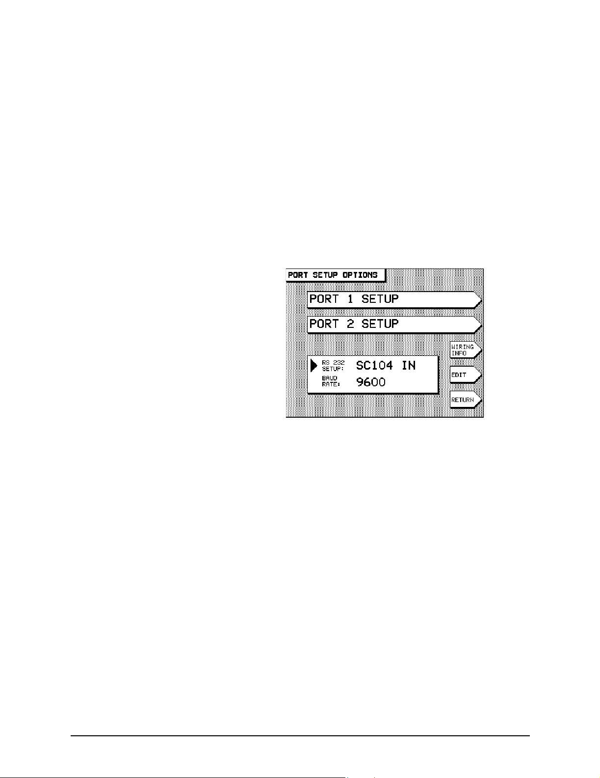
SECTION THREE Interfacing the unit
For details about interfacing the unit to the Northstar 8401,
you may want to refer to the Northstar 8401 Manual (GM465).
For details about interfacing the unit to the Northstar 8800,
you may want to refer to the Northstar 8800/8801 Beacon
Receiver Installation Manual (GM635). For details about connecting to other sources of differential corrections, see the
manufacturer’s instructions for wiring information.
Next, set up the 951/952 to receive the data from the external
source, using the RS-232 interface port.
1. Press the
CUSTOMIZATION
2. Press the PORT SETUP OPTIONS menu key. The
following screen will be displayed (information displayed
in the
3. If you want to receive SC104 corrections through the
unit’s RS-232 interface port, the port information box in
the lower center of the screen must read
port is set for anything other than
EDIT menu key, then press the CURSOR PAD to display
SC104 IN, then press the ENTER key.
4. Use this same procedure to set the baud rate to match
that of the external device, if necessary. (Refer to the
external device’s instructions for correct baud rate
setting.) The unit is now configured to accept differential
corrections from an outside source.
STAR key until you display the USER
screen.
RS-232 SETUP option at this time may be different):
SC104 IN. If the
SC104 IN, press the
Checking the quality of radiobeacon DGPS signals
Even if the unit is attached to an external source of
radiobeacon differential signals, the
DGPS NOT INSTALLED. This screen is functional only for
show
Northstar units that have an internal DGPS receiver (for
example, the 951XD/952XD); it doesn’t function in the 951XW/
952XW.
Page 46 951XW/952XW INSTALLATION MANUAL, Revision B
DGPS STATUS screen will
Page 57
SECTION THREE Interfacing the unit
Connecting to a Northstar
800 series loran
If a Northstar 800 series loran is already available on the vessel,
you can connect it to the 951/952 for an ideal source of
Loran-C TDs and previously stored waypoint locations. Use the
appropriate pin/wire connections and the 800’s setup sequence,
each listed below, to initialize the data output to be received by
the 951/952. You can use Port 1 or Port 2 of the 951/952, or A
or B of the 800. Wire colors refer to the unit’s interface cable.
Table 8: Connecting to Northstar 800 port A
800 OUTPUT ÷
Port A 951/952 Port 1 951/952 Port 2
Pin 12 brown (#3) white with brown stripe (#6)
Pin N blue (#1) brown with white stripe (#2)
÷ CONNECT TO EITHER øøøø
÷÷
Table 9: Connecting to Northstar 800 port B
800 OUTPUT ÷
Port B 951/952 Port 1 951/952 Port 2
Pin 7 brown (#3) white with brown stripe (#6)
÷ CONNECT TO EITHER øøøø
÷÷
Pin H blue (#1) brown with white stripe (#2)
To configure the Northstar 800 for correct output format,
follow the steps below (for further details, refer to the Northstar
800/800X Reference Manual, part number GM260):
1. Execute
84
COMMAND 83 for output port A, or COMMAND
for output port B.
2. Press the lower SELECT button until PRINTER 3 appears
in the lower display, and press
ENT.
3. Enter the following sequence to program the output
parameters:
Table 10: Northstar 800 series output port setup
At this prompt Press To output this data to the 951/952
SET UP 149 (ENT) 0183 output format (8 bits, no parity, 4800 baud)
INTERVAL 1 (ENT) 1 second output rate
ITEM 1 13 (ENT) include GTD sentence in output (Loran-C TDs)
ITEM 2 26 (ENT) waypoint location*
ITEM 3 31 (ENT) include SRS sentence in output
(status of received signals)
ITEM 4 40 (ENT) include RMA sentence in output
ITEM 5 0 (ENT) end of sequence
951XW/952XW INSTALLATION MANUAL, Revision B Page 47
Page 58
SECTION THREE Interfacing the unit
Table 10: Northstar 800 series output port setup (continued)
At this prompt Press To output this data to the 951/952
* Only used if you want the waypoint to which you’re navigating to be automatically
transferred to the unit’s waypoint database.
Connecting to other
devices
Ye om an wi re s 951/952 port 1 951/952 port 2
NMEA OUT (white)
(DATA A+)
Data Return (green)
(GROUND)
NMEA IN (red)
(DATA +)
RETURN (black)
(GROUND)
Connecting with a Yeoman chart plotter
To enable the 951/952 to communicate with a Yeoman
electronic chart plotter, refer to the table below.
Table 11: Yeoman plotter setup with the unit
÷÷÷÷ CONNECT TO EITHER øøøø
NMEA IN (brown #3) white with brown stripe (#6)
white with blue stripe (#4) white (#5)
NMEA OUT (violet#12) yellow (#15)
blue with white stripe (#8) black (#10)
Connecting with a radar device
The 951/952 can be set to interface with a radar device. The
951/952 supports the NMEA TLL sentence, sometimes referred
to as the “rattle” sentence. This sentence lets the unit
communicate its position to an interfaced radar device, which
tracks a user-defined target. In turn, the interfaced radar device
communicates to the unit the target’s position—in lat/lon
coordinates—so that you can see the target symbol, displayed as
a waypoint, right on the
position). The target symbol is displayed with the name
-RADAR on the CHART screen, as well as on both the ALPHA
LOCAL waypoints lists (to access these lists, press the
and
WAYPTS/ROUTES key, then WAYPT LIST menu key, then the
NEXT LIST menu key until you reach the desired list). On the
ALPHA and LOCAL lists, this radar waypoint is displayed with
the hours/minutes/seconds/day/month/year (for example,
12:50:20-30JUN99) in the description field.
CHART screen (after you save the
Page 48 951XW/952XW INSTALLATION MANUAL, Revision B
Page 59
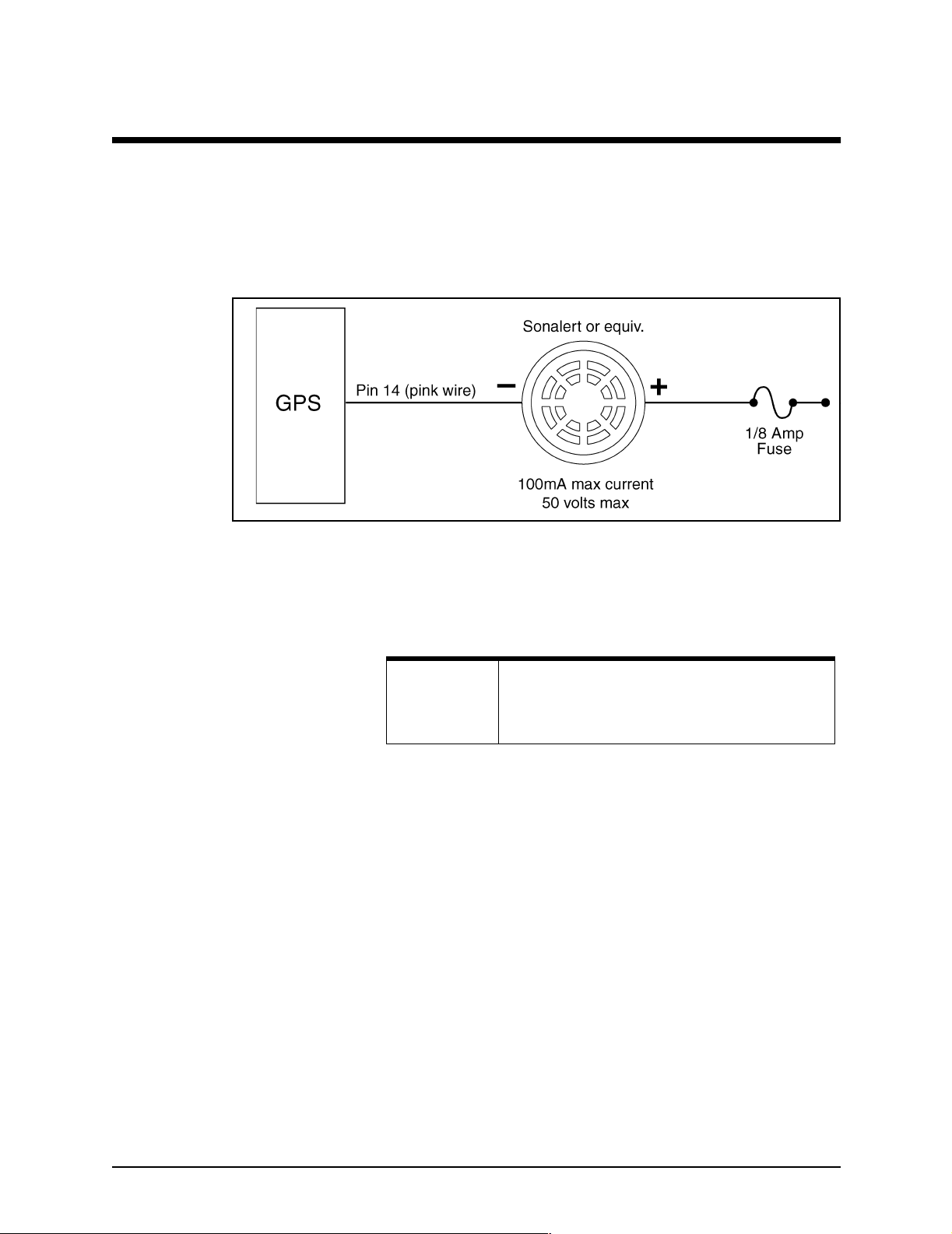
SECTION THREE Interfacing the unit
Setting the anchor-watch alarm honk
In the anchor-watch alarm function, you can set the 951/952 to
honk, in addition to beep, as long as you’ve connected a honker
with pin #14 on the interface connector. See Figure 16 on page
49 for the hardware modification required to support the unit’s
honk feature. You can use Radio Shack part number 273-060,
or an equivalent.
Figure 16: Pin 14 honk alarm interface
Once you’ve set the anchor-watch alarm to honk, a continuous
honking sequence begins either when your vessel moves
outside the specified anchor-alarm radius or when the
navigation source (for example, GPS) becomes unavailable.
NOTE:
To set the anchor-watch alarm to honk:
1. Press the
(952) or
2. Press the CURSOR PAD to highlight the HONK OUTPUT
option, then press the
3. Press the CURSOR PAD to select ANCHOR ALM, then
press the ENTER key.
If the vessel moves outside the set anchor-alarm radius, then
for the next 10 seconds, the exclamation point begins flashing
and the alarm automatically starts beeping (you’ll hear the
beeping only if you’ve set the
ALARMS or ALARMS & BACKLIGHT screen to ON). The honk
sequence then starts for a total of 3.5 minutes: 1 second of
honking followed by 14 seconds of silence; 2 seconds of
honking followed by 13 seconds of silence; 3 seconds of
honking followed by 12 seconds of silence, and so forth, until
the honking is up to 14 seconds followed by 1 second of
For this feature to work, the ANCHOR ALARM
option on the ALARMS screen (952) or ALARMS
& BACKLIGHT
STAR key once to display the ALARMS screen
ALARMS & BACKLIGHT screen (951).
screen (951) must be set to ON.
EDIT ALARM menu key.
ALARM AUDIO option on the
951XW/952XW INSTALLATION MANUAL, Revision B Page 49
Page 60

SECTION THREE Interfacing the unit
silence. This 3.5-minute honk cycle repeats forever unless you
clear the anchor alarm.
This honk does not automatically clear with the following
conditions:
• the vessel moves back into the anchor-alarm radius
• you change the anchor-alarm radius
• you select a new “drop anchor” position
• you turn off the anchor alarm
Instead, you must clear the anchor alarm in either of the
following two ways.
Option #1:
1. Press the
BACKLIGHT
STAR key to display the ALARMS/ALARMS &
screen, then press the CLEAR ALARM menu
key.
Option #2:
1. Press the
BACKLIGHT
STAR key to display the ALARMS/ALARMS &
screen.
2. Press the CURSOR PAD to highlight the HONK OUTPUT
option, then press the EDIT ALARM menu key.
3. Press the CURSOR PAD to select either 200 PPNM (used
to interface to speed log devices), or
instead of
ANCHOR ALM, then press the ENTER key.
ALL ALARMS,
Honking for all alarms Instead of setting all alarms to beep only, you can set all alarms
to honk. This honking starts simultaneously with the flashing
exclamation point on the
BACKLIGHT
screen (951). After you set all alarms to honk, the
system emits an output sound for half a second, followed by
silence for half a second. This repeatable honking sequence
stops when the alarms either automatically clear or you
manually clear them.
ALARMS screen (952) or ALARMS &
NOTE:
If you want all alarms to honk, you must first set the
ALARM AUDIO option to ON.
To set all alarms to honk:
1. Press the
ALARMS & BACKLIGHT screen (951).
or
STAR key to display the ALARMS screen (952)
2. Press the CURSOR PAD to highlight the HONK OUTPUT
option, then press the
3. Press the
press the
CURSOR PAD to select ALL ALARMS, then
ENTER key.
EDIT ALARM menu key.
Table 12 below describes how to set the anchor-watch alarm
and all other alarms to the desired audio.
Page 50 951XW/952XW INSTALLATION MANUAL, Revision B
Page 61

SECTION THREE Interfacing the unit
Table 12: Beep and honk settings for all alarms
Sound Type Setting(s) Description
Beep All alarms Set alarm audio field to ON The unit’s standard alarm beep.
Beep Anchor watch Set alarm audio field to ON
Set anchor alarm field to ON
Honk All alarms Set alarm audio field to ON
Set honk output field to ALL ALARMS
Honk Anchor watch Set anchor alarm field to ON
Set honk output field to ANCHOR ALM
Configuring the RS-232 port
The RS-232 port is used to interface to any of the following:
• an external differential receiver for Coast Guard
• an external device that accepts SC104 differential
• an external combined GPS receiver/antenna for GPS
• a personal computer
The unit’s standard alarm beep.
Exclamation point flashes on the
ALARMS screen; the unit simultaneously emits an output sound for half a
second, followed by silence for half a
second.
For 10 seconds, the exclamation point
flashes on the ALARMS/ALARMS &
BACKLIGHT screen and the alarm
beeps (if alarm audio is on), then the
honk sequence starts.
radiobeacon signals
corrections (future)
(and/or WAAS) and Coast Guard radiobeacon signals
(future)
Connecting to a differential receiver lets the unit receive
differential corrections through the RS-232 port. This function
is useful if you want to navigate using Coast Guard
radiobeacon differential corrections.
If you want to download waypoints to a personal computer, or
have your dealer or Northstar upgrade the 951/952 with new
operating software, you can connect to a PC using the RS-232
port. The following sections describe the RS-232 port’s various
settings.
Using SC104 out Because the 952XW and 952XW have no internal radiobeacon
receiver,
intended for sending radiobeacon differential signals to an
external device.
951XW/952XW INSTALLATION MANUAL, Revision B Page 51
SC104 OUT is not currently available. SC104 OUT is
Page 62

SECTION THREE Interfacing the unit
Using SC104 in SC104 IN accepts differential corrections from any external
Using external GPS In the future, the EXTERN GPS option will let you interface to
source transmitting the standard SC104 data stream. Use this
setting if you want to receive Coast Guard radiobeacon
differential corrections from an external source. When using
SC104 IN, be sure that the BAUD RATE setting also matches the
baud rate requirements of the transmitting device.
an external Northstar GPS receiver/antenna for receiving GPS,
(and/or WAAS) and Coast Guard radiobeacon signals.
Using copy port 1 and copy
port 2
NOTE:
The COPY PORT function allows you to interface the 951/952
to many personal computers without the need for an
RS-422-to-RS-232 converter. Many PC application programs for
waypoint/route loading, chart programs, data logging, etc., can
be used. The function “copies” the output of the specified port
1 or port 2 data format (
CDX,
or RAYTHEON 0183) to the RS-232 port’s output for direct
connection to the computer.
1. Press the
CUSTOMIZATION
OPTIONS
2. At the PORT SETUP OPTIONS screen, press the PORT 1
SETUP
port you want to copy is now set to output the desired
data format. If necessary, make changes now by pressing
EDIT menu key, pressing ENTER when done, and the
the
RETURN menu key to go back to the PORT SETUP
OPTIONS
3. At the PORT SETUP OPTIONS screen, if necessary, change
RS-232 SETUP option to display the appropriate COPY
the
PORT 1
menu key, then pressing the
the selection, then pressing the
now copy and output the specified port’s data format
through the RS-232 port to an external device.
If you haven’t interfaced an external combination
GPS receiver/antenna to the unit AND you select
EXTERN GPS option, no position data will be
the
shown and a communication failure will result.
NMEA 0180, NMEA 0183, DATAMARINE
STAR key to display the USER
screen, then press the PORT SETUP
menu key.
or PORT 2 SETUP menu key to confirm that the
screen.
or COPY PORT 2 selection by pressing the EDIT
CURSOR PAD to change
ENTER key. The unit will
Page 52 951XW/952XW INSTALLATION MANUAL, Revision B
Page 63

SECTION THREE Interfacing the unit
The RS-232 diagnostic port may overflow—when
it’s configured to either
PORT2
, and one of the copied ports is in 0183
output mode—unless the diagnostic port’s baud
rate is fast enough to handle the number of
characters. Because the diagnostic port’s baud rate
can now be changed, the unit will always display
this precautionary message before you actually
reset the baud rate:
SENTENCES MAY NOT TRANSMIT AT DIAG
BAUD RATE. PRESS “ENTER” TO CONTINUE
COPY PORT1 or COPY
WARNING: ALL
About the diagnostic
option
NOTE:
The RS-232 port’s DIAGNOSTIC option is for factory diagnosis
of 951/952 operating parameters. Do not turn this function on.
Using the “port off” setting Use this setting when the RS-232 port’s input or output
functions are not needed.
Ordering 951/952 software updates
For dealers Once Northstar has posted an addendum on its website, dealers
For end users End users should contact their respective dealer for these
Periodically, Northstar posts 951/952 software-update addenda
on its website (www.northstargps.com) under the “Manuals”
link.
who would like the corresponding software update can call the
Northstar Sales Department to order the particular update,
which is shipped with complete installation instructions. When
you call, be sure to have the current software version number
ready. To access this information about the unit, press the
STAR key until you display the USER CUSTOMIZATION screen,
then press the
SERVICE INFORMATION screen: The software version is
the
displayed in the
updates. Software updates should be installed by a qualified
marine technician. Updates that are installed improperly may
result in the loss of data and the incorrect functioning of the
unit. This type of repair isn’t authorized under the Northstar
warranty.
SERVICE INFORMATION menu key to display
MAIN BOARD SOFT VER: field.
951XW/952XW INSTALLATION MANUAL, Revision B Page 53
Page 64

SECTION THREE Interfacing the unit
Page 54 951XW/952XW INSTALLATION MANUAL, Revision B
Page 65
951/952
APPENDIX A Te c h n i c a l specifications
Table 13: 951/952 specifications
Power
Power source 10-40 VDC
12 watts nominal
Standard supplied fuse: 3 amps
GPS receiver
Type 12-channel, continuous tracking (2 channels dedicated for WAAS
differential corrections)
L1 frequency, C/A code (SPS)
Sensitivity C/N
951XW/952XW INSTALLATION MANUAL, Revision B Page 55
>34dB-Hz
0
Page 66
APPENDIX A Technical specifications
Navigation accuracy <3m 2DRMS with WAAS
Navigation update rate 1 per second
Time to first fix 30 seconds (typical)
Table 13: 951/952 specifications (continued)
1-3m 2DRMS with radiobeacon differential
20-30 m 2DRMS without differential
Dynamics Velocity:1800 km/h
Acceleration: 4 m/s
Jerk: 2 m/s
3
2
Interfacing
NMEA Two bi-directional ports
NMEA output sentences: APB, BOD, BWC, GGA, GLC, GLL, GSA,
GSV, HSC, MSS, RMC, RMA, RMB, BTG, WCV, XTE, ZDA, ZTG
(conforms to NMEA v 2.0 and later; supports 1.5 GLL and BWC)
NMEA input sentences: TLL, WPL, and others
RS-232 One bi-directional port
Other Waypoint upload/download capability (with appropriate software)
Operating software upload
Accepts external loran receiver
Accepts external combined GPS receiver/antenna (future)
Physical features
Display screen 320 x 240 pixel (5.75" diagonal)
High-temperature, backlit, transflexive graphics LCD (full-color, if
the 952)
Anti-reflection coated to minimize glare
Environmental
Temperature 0ºC – 55ºC max for the 951
0ºC – 50ºC max for the 952
95% relative humidity, non-condensing
Page 56 951XW/952XW INSTALLATION MANUAL, Revision B
Page 67

APPENDIX A Technical specifications
IEC compliance The following table applies only to the Northstar 951.
Immunity to electromagnetic environment (1988/1992 amend.)
Table 14: Standards for IEC compliance
Evaluation Standard
Radiated emissions IEC 945 (1995) per 17.3, 17.4
Low temperature IEC945 (1995) per 4.5.4.2.4
Dry heat IEC 945 (1995) per 4.5.2
Damp heat IEC 945 (1995) per 4.5.3
Corrosion IEC 945 (1995) per 4.5.10
Vibration IEC 945 (1995) per 4.5.7
Rain test IEC 529–IPX 5
Internal WAAS differential receiver specifications
Velocity: 1852 km/h (514 m/s)
Acceleration: 4 Gs 939.2 m/s
Jerk: 2 m/s
Time to first fix: 50 seconds
Accuracy: <2 m (cep)
3
AN150 Antenna Height: 2.7 inches
Diameter: 3.0 inches
Weight: 0.5 pounds
2
)
951XW/952XW INSTALLATION MANUAL, Revision B Page 57
Page 68

APPENDIX A Technical specifications
Page 58 951XW/952XW INSTALLATION MANUAL, Revision B
Page 69

Numerics
951/952
chart cartridge, proper insertion of
connecting to other Northstar units 41
dimensions (side and front) 12
installing 7
interfacing to other equipment 31
ordering spare parts 8
pre-installation checkout 10
safety concerns while installing 7
servicing the unit 4
RMA number 5
testing and troubleshooting the unit 27
turning the unit off 27
turning the unit on 23
wiring the unit 16
A
Accuracy of signals
Alarm
anchor
audible 49–51
AN150 antenna
choosing a location
flaring the end of the cable braid 21
location 18
mounting 20
overview 10
recommended separation distances 19
stripping the coax cable jacket 21
tools needed for installation 20
troubleshooting 29
Anchor-watch alarm, honk setting 49
Antenna, AN150. See AN150 antenna
C
Cautions
installing the antenna
installing the unit 8, 9
mounting the unit 16
servicing the unit 5
wiring the unit 16
Chart cartridge, proper insertion of 24
Checksums 40
COG readings 18
Configuring output ports 34
Copy port 1 and 2, using 52
D
Datamarine CDX output format
F
Flush mounting
drilling dimensions 15
G
GPS
49–50
2, 26
18, 19
20
36
14
Index
23
951XW/952XW INSTALLATION MANUAL, Revision B PAGE 59
Page 70

accuracy 26, 39
and differential corrections 2
quality of signals 26
troubleshooting 27
H
Honk, setting the unit’s anchor-watch alarm to
I
Input ports
Inputs
NMEA port
RS-232 port 31, 45, 53
Interfacing
200 pulses per nautical mile (PPNM)
compatibility 31, 35, 38
connecting to external combination receiver/antenna 2, 45
connecting to external combined GPS receiver/antenna 52
connecting to external Northstar model 8400, 8401, or 8800 differential receiver 45
connecting with other devices
connector pin wiring 32
L
Lat/lon, changing the precision settings
Loran
connecting the unit to a Northstar 800
interfacing with GPS 47
M
Mounting
AN150 antenna
flush-mounting and yoke-mounting the 951/952 14
N
NMEA 0183
checksums 40
lat/lon precision, setting 39
output-port datum 41
sentence identifiers, turning on and off 37
talker ID 38
waypoint ID 40
Noise 17
Northstar 800 series loran 47
Northstar service department 3
O
Outputs
200 ppnm
changing output rate 39
format 35
NMEA port 31, 33, 34
RS-232 port 31, 45, 53
P
Parts, ordering
Port setup options
connecting to Northstar 800
NMEA port 34
programming the ports 34
45
31, 33
chart plotters
radars 48
31, 34
33
8
33
48
39
20
47
49
41
PAGE 60 951XW/952XW INSTALLATION MANUAL, Revision B
Page 71

RS-232 port 51
wiring information screen 32
Pulses per nautical mile (PPNM) 33
R
Radar, interfacing the unit with
Radiobeacon differential GPS 2, 45–46, 51–52
Raytheon 0183 output format 36
RMA number 5
RS-232 45
configuring port 51–53
copy port 1 and 2 52
SC-104 in 46, 52
SC-104 out 51
S
Screens
ALARMS/ALARMS & BACKLIGHT
CHART 48
CHART SETUP/STATUS 23
DGPS STATUS 46
GPS POSITION 26
GPS SATS 26
INTERFACE CABLE WIRING 32
PORT SETUP OPTIONS 32, 34, 52
SERVICE INFORMATION 53
USER CUSTOMIZATION 32, 52, 53
Sentences, NMEA 0183 identifers 37
Service. See Technical support
Software updates, ordering
T
Talker ID
TDs (time differences) 47
Technical support 3, 53
TNC connector 20, 21
Transferring waypoints between two Northstar units 41
Troubleshooting
Turning off the 951/952 27
Turning on the 951/952 24
U
Updates, ordering
W
WAAS
Warranty statement 3
Waypoints, setting identifier (names or numbers) 40
Wiring
Y
Yoke mounting
38
the antenna
the installation 27
29
53
accuracy
quality of signals 26
troubleshooting 27
951/952
installation 18
2, 26
16
14
48
49, 51
53
951XW/952XW INSTALLATION MANUAL, Revision B PAGE 61
Page 72

PAGE 62 951XW/952XW INSTALLATION MANUAL, Revision B
 Loading...