

Page 1

RETURN TO SERVICE PROCEDURE TABLE OF CONTENTS
KIT,YOKERELOCATIONTOREAR
YOKERELOCATIONPROCEDURE
RETURN TO CD-ROM TABLE OF CONTENTS
1. Disconnectallpipelinehosesand
turntheSystemPowerswitchto
ON.
2. Closeallcylindervalvesexceptthe
O
cylindervalve.
2
3. Settheoxygenflowrateto5l/min.
4. OpentheN
Oflowcontrolvalveto
2
drainpressurefromthesystem.
5. ClosetheO
cylindervalve,and
2
closetheflowcontrolvalves.Press
theO
FLUSHbuttontodrain
2
pressurefromthesystem.
6. TurntheSystemPowerswitchto
STANDBYandremoveACpower
fromthemachine.Disableall
circuitbreakers.
7. Removethescrewssecuringthe
tabletoptothemachine,and
removethetop.
8. Loosenthefittingsateachendof
thetubeconnectingtheoxygen
yoketotheoxygenregulator,and
removethetube.
9. Loosenthefittingsateachendof
thetubeconnectingthenitrous
oxideyoketothenitrousoxide
regulator,andremovethetube.
10. Removethescrewsandwashers
securingtheyokestothemachine;
removetheyokeassembliesand
mountingspacers.
11. Installthenitrousoxideyokeon
therearofthemachine,locatedas
showninFigure1.Formachines
withamountingspacer,usethe
mounting hardware that was
previouslyremoved.Formachines
withoutamountingspacer,usetwo
5/16-24x¾in.skthdscrews(P/N
HW01056).
12. Installtheoxygenyokeontherear
ofthemachine,locatedasshownin
Figure1.Formachineswitha
mountingspacer,usethemounting
hardware that was previously
removedandensurethattheyoke
islevel.Formachineswithouta
mountingspacer,usetwo5/16-24x
¾ in. skt hd screws (P/N
HW01056).
NOTE:
Examinethetubingthatwas
removedanddeterminethetypeof
fittingstobeusedattheregulator
connections.Figure2showsthe
correctassemblyfortwotypesof
compressionfittings.
13. Assemblethecorrectcompression
fittingsonpre-benttube(P/N
4111168 for machines with a
mountingspacer;P/N4108491for
machines without a mounting
spacer).Installthetubefromthe
nitrousoxideyoketothenitrous
oxideregulatorandtightenthe
fittingssecurely.Installablue
"N
O"labeloneachendofthis
2
tube.
1
Page 2
RETURN TO SERVICE PROCEDURE TABLE OF CONTENTS
YOKE RELOCATION PROCEDURE (continued)
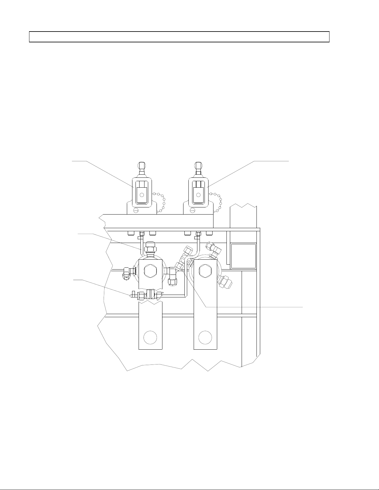
TOP VIEW OF ANESTHESIA MACHINE
WITH TABLE TOP REMOVED
RETURN TO CD-ROM TABLE OF CONTENTSRETURN TO CD-ROM TABLE OF CONTENTS
N2O YOKE
ASSEMBLY
(RELOCATED)
N2O TUBING
(INSTALL)
O2 TUBING
(INSTALL)
O2 YOKE
ASSEMBLY
(RELOCATED)
N2O
REGULATOR
CONNECTION
SP11001
Figure 1: YOKE RELOCATION AND TUBING CONNECTIONS
2
Page 3

IMPERIAL
TYPE
COMPRESSION NUT
AND FERRULE
COPPER
TUBING
COMPRESSION
NUT
TWO-PIECE
FERRULE
1/8in.
SWAGELOK
TYPE
RETURN TO SERVICE PROCEDURE TABLE OF CONTENTS
YOKE RELOCATION PROCEDURE (continued)
RETURN TO CD-ROM TABLE OF CONTENTSRETURN TO CD-ROM TABLE OF CONTENTS
Figure 2: COMPRESSION FITTING STYLES
14. Assemble the correct compression
fittings on pre-bent tube (P/N
4111167 for machines with a
mounting spacer; P/N4108492 for
machines without a mounting
spacer). Install the tube from the
oxygen yoke to the oxygen regulator
and tighten the fittings securely.
Install a green "O
" label on each
2
end of this tube.
15. If additional yokes were removed,
install plugs into the regulator
fittings as needed.
16. Install an oxygen cylinder in the O
yoke, and a nitrous oxide cylinder
in the N
O yoke.
2
b. Close the cylinder valve and remove
c. Observe the cylinder pressure
18. Perform the following oxygen
a. Turn the System Power Switch to
b. Connect a 12 inch hose to the
2
c. Set the Man/Auto selector to BAG.
the cylinder from the yoke.
gauge; after two minutes the
pressure shall not drop more than
50 psi.
concentration test:
ON.
inspiratory valve.
17. Performthefollowinghighpressure
leak test for each yoke:
a. Open the cylinder valve and allow
the pressure to stabilize.
3
d. Close the APL valve.
e. Occlude the bag mount.
Page 4

RETURN TO SERVICE PROCEDURE TABLE OF CONTENTS
YOKE RELOCATION PROCEDURE (continued)
RETURN TO CD-ROM TABLE OF CONTENTSRETURN TO CD-ROM TABLE OF CONTENTS
f. Insert the sensor from a calibrated
MED into the valve dome adaper
O
2
on the inspiratory valve.
g. Close all flow control valves.
h. Install the appropriate cylinder in
each yoke, and open one cylinder
valve for each gas.
i. Depress the O
FLUSH button for
2
15 seconds.
j. Set the oxygen flow to 4 l/min.
k. Within three minutes the O
shall read 97-100% oxygen.
l. Set the nitrous oxide flow to 2
l/min.
PARTS REQUIRED
MED
2
m. The oxygen concentration shall be
64-70%.
n. Set the nitrous oxide flow to 4
l/min.
o. The oxygen concentration shall be
47-53%.
p. Close all flow control valves.
19. Replace the table top on the
machine and secure it with the
screws that were previously
removed.
20. Perform a complete PMS procedure
on the machine.
PART DESCRIPTION PART NUMBER
Tube, 3/16 in. dia. cu "bent" (N2O) (Machines w/ spacer) 4111168
Tube, 3/16 in. dia. cu "bent" (O2) (Machines w/ spacer) 4111167
Tube, 3/16 in. dia. cu "bent" (N2O) (Machines w/o spacer) 4108491
Tube, 3/16 in. dia. cu "bent" (O2) (Machines w/o spacer) 4108492
Screw, 5/16-24 x ¾ in. skt hd (4x) (Machines w/o spacer) HW01056
Nut, 3/16 in. Tubing (4x) 4104716
Ferrule, Two Piece (2x) (Supplied as a set of 10) 4111038
Nut, Fitting, 3/16 Tubing (2x) 4109489
Label, "N2O" Tubing (4x) 4109874
Label, "O2"Tubing 4109871
Plug, Fitting, 3/16 Tube (2x) 4109400
Plug, Fitting, 3/16 Tube (2x) 4106052
4
Page 5

NORTH
RETURN TO SERVICE PROCEDURE TABLE OF CONTENTS
RETURN TO CD-ROM TABLE OF CONTENTSRETURN TO CD-ROM TABLE OF CONTENTS
AMERICAN
DRÄGER
Technical Service Department
22 Commerce Drive
Telford, Pennsylvania 18969
Telephone: (215) 721-5402
(800) 543-5047
Facsimile: (215) 723-5935
Quality Service for Life
®
Part Numbers: SP00110
Rev: Date: November 25, 1992
© 1992 N.A.D., Inc.
 Loading...