


RETURN TO THIS MANUAL'S TABLE OF CONTENTS
RETURN TO CD-ROM TABLE OF CONTENTS
Vamos
Variable Anesthetic Gas Monitor
Technical
Documentation

RETURN TO CD-ROM TABLE OF CONTENTS
Contents
Function Description
1 |
Introduction |
7 |
|
|
1.1 |
What’s what? .......................................................................................... |
7 |
|
1.2 |
Screen content ........................................................................................ |
8 |
|
1.3 |
Operating modes .................................................................................... |
9 |
2 |
Operating concept |
9 |
|
|
2.1 |
Power-up behavior ................................................................................ |
10 |
|
2.2 |
Alarms ................................................................................................... |
10 |
|
2.3 |
Menu structure ....................................................................................... |
11 |
|
2.4 |
Simplified Vamos block diagram ........................................................... |
12 |
3 |
ILCA patient gas module |
13 |
|
|
3.1 |
Patient gas module structure ................................................................ |
14 |
|
3.2 |
Sensor head function ............................................................................ |
15 |
|
3.3 |
Sensor head operation ........................................................................ |
20 |
|
3.4 |
Measured value units ............................................................................ |
21 |
|
3.5 |
Pneumatic system ............................................................................... |
22 |
|
3.6 |
Tubing ................................................................................................... |
22 |
|
3.7 |
Pump .................................................................................................... |
23 |
|
3.8 |
MOPS PCB ........................................................................................... |
24 |
|
3.9 |
AMO FLOW ILCA PCB (flow controller) ............................................... |
26 |
21.08.02 |
only. Copyright reserved. |
D6494340T01IVZ.fm |
For internal use |
6494.340 Vamos |
Contents |
2 |

21.08.02 |
only. Copyright reserved. |
D6494340T01IVZ.fm |
For internal use |
RETURN TO THIS MANUAL'S TABLE OF CONTENTS
RETURN TO CD-ROM TABLE OF CONTENTS
Contents |
|
|
4 |
AMO O2 GRAF PCB |
29 |
5 |
VAMOS PCB |
31 |
6 |
SpO2 PCB |
32 |
7 |
Screen |
32 |
8 |
Water trap |
32 |
9 |
Desktop power pack |
33 |
10 |
Starting the release mode |
34 |
|
10.1 Screen content release mode ............................................................... |
35 |
|
10.2 Entering the release code ..................................................................... |
35 |
Service Mode |
|
|
1 |
Starting the service mode |
37 |
|
1.1 Explanation of screen content .............................................................. |
38 |
Repair Instructions
1 |
Service strategy |
39 |
|
2 |
VAMOS service programs |
40 |
|
|
2.1 |
Download program ............................................................................... |
40 |
|
2.2 |
VISIA program ...................................................................................... |
40 |
6494.340 Vamos |
Contents |
3 |

21.08.02 |
only. Copyright reserved. |
D6494340T01IVZ.fm |
For internal use |
RETURN TO THIS MANUAL'S TABLE OF CONTENTS
RETURN TO CD-ROM TABLE OF CONTENTS
Contents
3 |
Repair information list |
41 |
|
4 |
Hardware configuration of VAMOS |
42 |
|
|
4.1 |
Repair components ............................................................................... |
44 |
5 |
ILCA |
|
45 |
|
5.1 |
Electrical data of ILCA sensor head ..................................................... |
45 |
|
5.2 |
Pneumatic system ................................................................................ |
48 |
|
5.3 |
AMO FLOW ILCA PCB ......................................................................... |
50 |
6 |
Options |
51 |
|
|
6.1 |
Optional battery .................................................................................... |
51 |
|
6.2 |
SpO2 option .......................................................................................... |
52 |
7 |
Alarms and their meaning |
53 |
|
|
7.1 |
Behavior of Vamos in case of alarms ................................................... |
53 |
|
7.2 |
General alarms ..................................................................................... |
54 |
|
7.3 |
SpO2 measurement alarms .................................................................. |
54 |
|
7.4 |
Gas measurement alarms .................................................................... |
57 |
8 |
Vamos disassembly |
61 |
|
|
8.1 |
Housing rear panel disassembly ........................................................... |
61 |
|
8.2 |
Basic frame disassembly ...................................................................... |
62 |
|
8.3 |
ILCA module disassembly .................................................................... |
63 |
|
8.4 |
PCB-set disassembly ............................................................................ |
65 |
|
8.5 |
VAMOS PCB disassembly .................................................................... |
68 |
|
8.6 |
ILCA sensor-head disassembly ............................................................ |
68 |
|
8.7 |
Pump disassembly ................................................................................ |
69 |
6494.340 Vamos |
Contents |
4 |

21.08.02 |
only. Copyright reserved. |
D6494340T01IVZ.fm |
For internal use |
RETURN TO THIS MANUAL'S TABLE OF CONTENTS
RETURN TO CD-ROM TABLE OF CONTENTS
Contents
Software download
1 |
Software download (PGM or MFM software) |
70 |
|
|
1.1 |
Software download precautions ............................................................ |
70 |
|
1.2 |
Test Equipment ..................................................................................... |
71 |
|
1.3 |
Typographic Conventions ..................................................................... |
71 |
|
1.4 |
Software Download Procedure ............................................................. |
72 |
VISIA program
1 |
VISIA program description |
79 |
|
1 |
Error list to function blocks |
82 |
|
|
1.1 |
Monitor .................................................................................................. |
82 |
|
1.2 |
Rechargeable battery ........................................................................... |
83 |
|
1.3 |
Measured value display ........................................................................ |
85 |
|
1.4 |
Text display ........................................................................................... |
88 |
|
1.5 |
Menu ..................................................................................................... |
89 |
|
1.6 |
Keys ...................................................................................................... |
93 |
|
1.7 |
Control knob ......................................................................................... |
94 |
|
1.8 |
LEDs ..................................................................................................... |
95 |
|
1.9 |
Acoustic signal ...................................................................................... |
96 |
|
1.10 |
Serial communication ........................................................................... |
97 |
|
1.11 |
Processor .............................................................................................. |
97 |
|
1.12 |
Software ................................................................................................ |
98 |
|
1.13 |
Fan ........................................................................................................ |
99 |
6494.340 Vamos |
Contents |
5 |

RETURN TO THIS MANUAL'S TABLE OF CONTENTS
RETURN TO CD-ROM TABLE OF CONTENTS
Contents
Schematics and Diagrams
1 VAMOS block diagram |
100 |
PMS
1. |
Unit, general |
101 |
2. |
Spare parts used |
102 |
3. |
Safety Checks |
103 |
4. |
Test items |
106 |
5. |
Supply unit to customer ready for operation. |
111 |
6. |
Confirmation of test |
111 |
7.These steps are regarded as repair work and are therefore not included in
the inspection service price. |
111 |
8. Annex |
112 |
Installation instructions |
114 |
Spare parts list |
118 |
21.08.02 |
only. Copyright reserved. |
D6494340T01IVZ.fm |
For internal use |
6494.340 Vamos |
Contents |
6 |
RETURN TO THIS MANUAL'S TABLE OF CONTENTS
RETURN TO CD-ROM TABLE OF CONTENTS
Function Description
1 Introduction
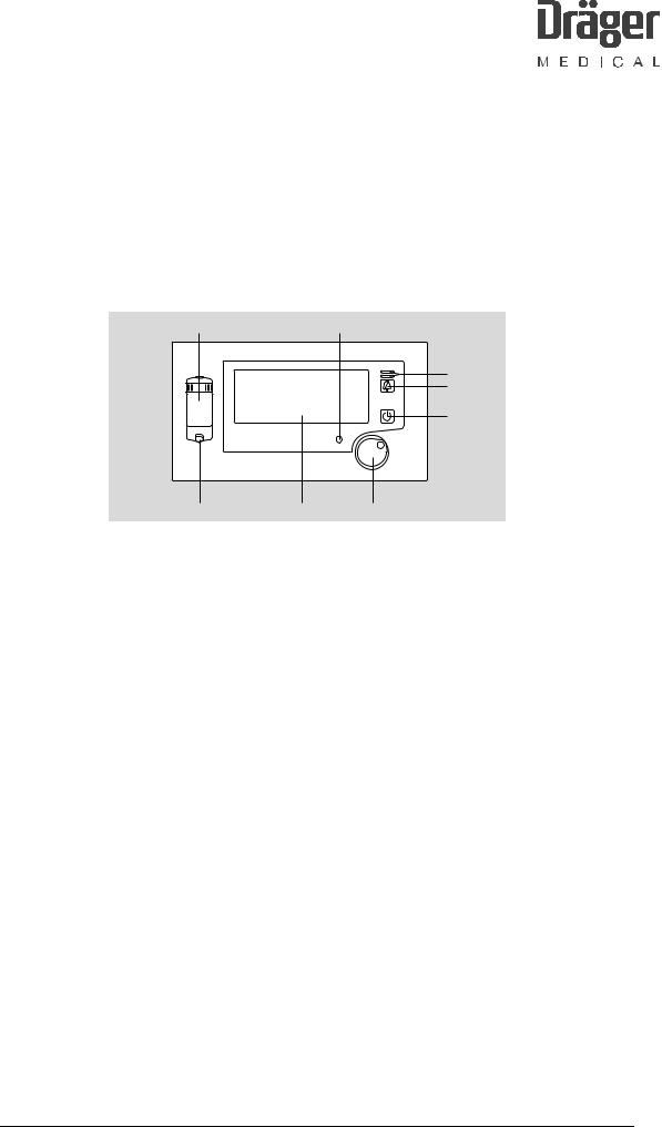
1.1What’s what?
|
7 |
|
6 |
|
|
|
|
|
5 |
|
|
|
|
4 |
|
|
|
|
3 |
|
D Vamos |
|
|
|
|
8 |
1 |
|
2 |
Key to front view |
|
|
|
|
1 |
Screen |
|
5 |
Indicator lamps for alarm |
2 |
Central control knob for selection and |
|
6 |
Power indicator lamp |
|
confirmation |
|
|
Mains voltage = green |
|
|
|
|
Battery operation = yellow |
3 |
Standby Key |
|
7 |
Water trap WaterLock |
4 |
Key for silencing the alarm sound for |
|
8 |
Connection for sampling line |
|
2 minutes |
|
|
|
F6494340T01.fm 21.08.02 |
All rights reserved. Copyright reserved. |
6494.340 Vamos |
Version 3.0 |
Function Description |
7 |
F6494340T01.fm 21.08.02 |
All rights reserved. Copyright reserved. |
RETURN TO THIS MANUAL'S TABLE OF CONTENTS
RETURN TO CD-ROM TABLE OF CONTENTS
15
|
|
|
|
|
|
|
|
|
|
|
|
|
|
|
|
|
|
|
|
|
|
|
|
|
|
|
|
|
|
|
|
|
|
|
|
|
|
|
|
|
|
|
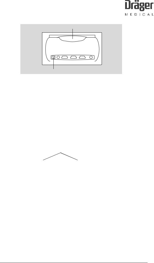
9 10 11 |
12 |
13 |
14 |
|
||||||||
Key to rear view |
|
|
|
|
|
|
|
|
|||||
9 |
ON/OFF switch |
|
|
13 |
"SpO2" connection for SpO2 |
||||||||
|
|
|
|
|
|
|
|
|
|
sensor |
|||
10 |
"15 V DC" connection for desktop power |
14 |
Outlet for sampling gas |
||||||||||
|
pack |
|
|
|
|
scavenging or return line |
|||||||
11 |
Connection for RS 232 interface |
|
|
15 |
Handle |
||||||||
|
(Medibus) |
|
|
|
|
|
|
|
|
||||
12 |
Connection for RS 232 interface |
|
|
|
|
|
|
|
|
||||
1.2Screen content
|
|
|
|
|
|
|
|
|
|
|
|
1 |
|
|
|
|
|
|
|
|
2 |
|
|
|
|
|
10 |
|
|
|
|
|
|
|
|
|
|
|
|
|
|
|
|
|
|
|
|
|
|
|
|
|
|
|
|
|
|
|
|
|
|
|
|
|
|
|
|
|
|
|
|
|
|
|
|
|
|
|
||
|
|
|
|
|
|
|
|
|
|
|
|
|
|
|
|
|
|
|
|
|
|
|
|
|
||
|
115 |
|
|
|
|
|
|
|
|
|
|
|
|
SpO2 |
0 |
|
|
|
3 |
|||||||
|
|
|
|
|
|
|
|
|
|
|
|
|
|
|
|
|
|
|||||||||
|
|
|
|
|
|
|
|
|
|
|
|
|
|
|
|
|
|
|
|
|
|
|
||||
9 |
|
|
|
|
|
CO2 |
|
|
|
|
|
|
|
|
|
|
|
|
HR |
0 |
|
|
|
|||
|
|
|
|
|
|
|
|
|
|
|
|
|
|
|
|
|
|
|
|
|||||||
|
|
|
|
|
|
|
|
|
|
|
|
|
|
|
|
|
|
|
|
|
||||||
8 |
|
|
|
|
|
|
|
|
|
|
|
|
|
|
|
|
|
|
|
|
|
|
|
|||
|
|
|
|
|
|
|
|
|
|
|
|
|
|
|
|
|
|
|
|
|
♥ |
|
|
|||
|
|
|
0 |
|
|
|
|
|
|
|
|
|
|
|
|
|
|
|
|
|||||||
|
|
|
|
|
|
|
|
|
|
|
|
|
|
|
|
|
|
|
|
|||||||
|
|
|
|
|
|
|
|
|
|
|
|
|
|
|
|
|
|
|
|
|
|
|
||||
|
|
|
|
|
|
|
|
|
|
|
|
|
|
|
|
|
|
|
|
|
|
|
|
|
|
|
|
|
|
|
|
|
|
Fi |
|
N2O |
0.0 |
Hal |
0.0 |
|
|
CO2 |
0 |
|
|
|
|
||||||
|
|
|
|
|
|
|
|
|
|
|
|
|
|
|
|
|
|
|
|
|
|
|
||||
|
|
|
|
|
|
|
Fet |
|
[%] |
0.0 |
[%] |
0.0 |
|
|
[mmHg] |
0 |
|
|
|
|
||||||
|
|
|
|
|
|
|
|
|
|
|
|
|
|
|
|
|
|
|||||||||
|
|
|
|
|
|
|
|
|
|
|
|
|
|
|
|
|
|
|
|
|
|
|
|
|
|
|
|
|
|
|
|
|
|
|
|
|
|
|
|
|
|
|
|
|
|
|
|
|
|
|
|
||
|
|
|
|
|
|
6 |
|
|
|
|
5 |
|
|
|
4 |
|
|
|
||||||||
|
|
|
|
7 |
|
|
|
|
|
|
|
|
|
|
|
|
||||||||||
Key to possible screen content |
|
|
|
|
|
|
|
|
|
|
|
|
|
|
|
|||||||||||
1 |
Alarm window |
|
|
|
|
|
|
8 |
|
Window for real-time curve |
||||||||||||||||
2 |
Status window |
|
|
|
|
|
|
9 |
|
Displayed parameter |
|
|||||||||||||||
3, 4, 5, Parameter window |
|
|
|
|
|
|
10 |
Scaling of real-time curve |
||||||||||||||||||
6, 7 |
|
|
|
|
|
|
|
|
|
|
|
|
|
|
|
|
|
|
|
|
|
|
|
|
|
|
6494.340 Vamos |
Version 3.0 |
Function Description |
8 |

RETURN TO THIS MANUAL'S TABLE OF CONTENTS
RETURN TO CD-ROM TABLE OF CONTENTS
1.3Operating modes
The operating modes of Vamos are defined as follows:
Measuring |
The measured values of the sensors are displayed on-screen. |
mode: |
|
Standby: |
Vamos is switched on. No measured value is shown on the |
|
screen, but the following message: |
|
”Standby” |
|
”Software XX.XX” (XX.XX = MFM software version) |
|
The light in the standby key should come on. In "Standby" mode |
|
the pump of the ILCA module is off. |
AC mains |
Vamos is in standby mode or in measuring mode and is powered |
supply |
from the desktop power pack. The power-on indicator light should |
operation: |
turn green. |
Battery |
Vamos is in standby mode or in measuring mode and is powered |
operation: |
from the internal rechargeable battery (optional). The power-on |
|
indicator light should turn yellow. |
Charging mode: |
The optional internal rechargeable battery is charged from the |
|
desktop power pack. |
No operation: |
None of the above operating modes is active. |
2 Operating concept
The central control element is the control knob on the front plate. The control knob has two functions:
−Rotate = select/set
−Press = confirm
The two buttons on the front plate have the following functions:
−Button to silence the alarm for 2 minutes.
−Standby key.
F6494340T01.fm 21.08.02 |
All rights reserved. Copyright reserved. |
6494.340 Vamos |
Version 3.0 |
Function Description |
9 |

RETURN TO THIS MANUAL'S TABLE OF CONTENTS
RETURN TO CD-ROM TABLE OF CONTENTS
2.1 |
Power-up behavior |
1. |
All LEDs are actuated. |
2. |
Bleeps and screen test |
3. |
LEDs are actuated one after the other. LED sequence: Standby, silence, advisory, |
|
alarm, standby....... |
4. |
Standby screen |
2.2 |
Alarms |
Vamos classifies alarm signals into three priorities, identified by up to three different exclamation marks. Alarm messages with a higher priority supersede those with a lower priority.
Alarm priority |
Alarm tone |
LED |
Alarm = !!! (highest priority) |
intermittent |
The red (top) LED |
|
|
flashes |
|
|
accompanied by a |
|
|
tone sequence at |
|
|
2.5-second |
|
|
intervals. |
Caution = !! (medium priority) |
intermittent |
The yellow |
|
|
(bottom) LED |
|
|
flashes |
|
|
accompanied by a |
|
|
tone sequence at |
|
|
30-second |
|
|
intervals. |
Advisory = ! (lowest priority) |
once |
The yellow |
|
|
(bottom) LED |
|
|
comes on |
|
|
accompanied by a |
|
|
single tone. |
F6494340T01.fm 21.08.02 |
All rights reserved. Copyright reserved. |
6494.340 Vamos |
Version 3.0 |
Function Description |
10 |
F6494340T01.fm 21.08.02 |
All rights reserved. Copyright reserved. |
RETURN TO THIS MANUAL'S TABLE OF CONTENTS
RETURN TO CD-ROM TABLE OF CONTENTS
2.3Menu structure
|
---> |
|
Alarm |
Agent |
|
CO2 |
||
SpO2 |
||
Sound |
||
Language |
||
Param. |
||
Config. |
||
Cal |
||
|
Alarm |
---> |
FiCO2 |
--- |
5.0 |
EtCO2 |
|
50.0 |
FiHal |
--- |
|
SpO2 |
92 |
1.5 |
Pulse |
50 |
120 |
Agent |
---> |
Hal |
Enf |
Iso |
Sev |
Des |
|
|
|
|
|
|
|
|
|
|
SpO2 |
|
|
|
|
|
---> |
|
|
|
|
Mode |
|
Slow |
|
|
|
|
|
|
|
|
Normal |
|
|
|
|
|
|
|
|
Fast |
|
|
|
|
|
|
|
|
|
|
|
|
Language |
de |
---> |
|
|
|
|
en |
|
|
fr |
|
|
es |
|
|
it |
|
|
nl |
|
|
sv |
|
Config. |
|
---> |
high |
|
|
Brightn. |
|
|
|
low |
|
Medibus |
1200 |
|
|
|
|
(Baud) |
9600 |
|
|
|
|
|
19200 |
|
CO2 |
|
---> |
|
|
|
Unit |
mmHg |
|
Vol% |
|
kPa |
Range |
0-75 |
|
0-110 |
Parameter |
|
|
|
|
|
---> |
|
|
Gases |
|
on |
|
|
|
|
|
|
off |
||
Sound |
---> |
|
|
Pulse |
0 |
SpO2 |
on |
Alarm |
1 |
|
|
||
|
off |
|
|
Fig. 1: Vamos menu structure
6494.340 Vamos |
Version 3.0 |
Function Description |
11 |
RETURN TO THIS MANUAL'S TABLE OF CONTENTS
RETURN TO CD-ROM TABLE OF CONTENTS
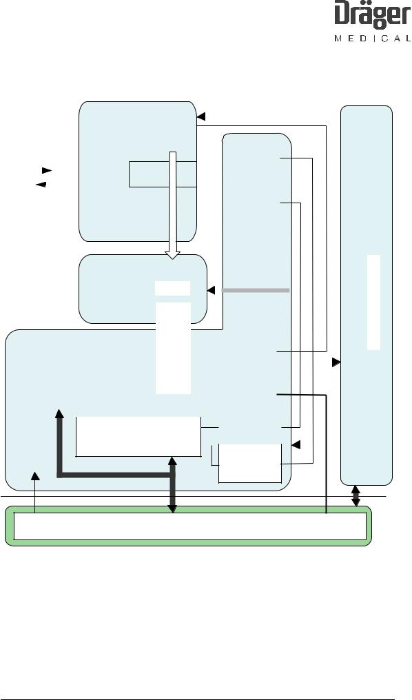
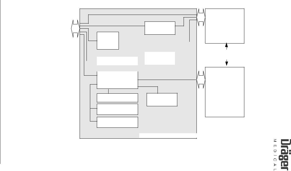
2.4Simplified Vamos block diagram
Rear
ON/OFF
Desktop power pack
RS 232
Medibus
RS 232
PC
SpO2
Sensor
Gas outlet |
|
|
|
Front |
|
12 V battery (option) |
Indicator |
|
|
|
|
|
|
|
|
lamps (LEDs) |
PCB |
|
PCB |
Control Knob |
Horn |
|
||
SpO2 |
Charge |
|
|
|
|
||
RS 232 |
|
|
Keys |
1.5 KV |
|
|
|
VAMOS PCB |
|
||
|
|
||
RS 232 |
|
|
|
1.5 KV |
RS 232 |
|
|
|
|
15 VDC |
Screen |
|
|
|
|
|
|
|
BUS |
|
RS 232 |
|
|
|
ILCA |
|
Water trap |
|
|
|
|
|
|
|
Fan |
Fig. 2: Vamos block diagram
The ILCA patient gas module has no automatic anesthetic detector. The anesthetic being used must be specified by the user. Only one anesthetic may be used at any one time. The ILCA patient gas module conforms to the accuracy specified in the ISO standard.
F6494340T01.fm 21.08.02 |
All rights reserved. Copyright reserved. |
6494.340 Vamos |
Version 3.0 |
Function Description |
12 |

F6494340T01.fm 21.08.02 |
All rights reserved. Copyright reserved. |
RETURN TO THIS MANUAL'S TABLE OF CONTENTS
RETURN TO CD-ROM TABLE OF CONTENTS
3 ILCA patient gas module
powerExt. supply |
|
(4 kV separation) |
|
|
SpO2sensor |
|
|
|
|
|
|
componentsthe |
inside the dashed line |
belong to the ILCA |
|
||
|
unit |
|
|
|
|
|
|
|
Sampling gas scavenging line |
|
|
Only |
module. |
||||
ON/OFF switch |
RS232 - PC |
RS232 - Medibus |
|
SpO2 PCB |
Screen |
Keypad with status LEDs |
Control Knob |
Water trap |
Particle |
filter |
|||||||
|
|
|
|
|
|
|
1,5 KV separation SpO2 |
|
|
|
Pump |
Valve |
ILCA sensor head |
|
|
|
|
|
with |
chargingcircuit |
(optional) |
|
|
VAMOSPCB |
|
|
|
|
|
|
|
|
|
|
|
|
Fan Battery |
(monitored) |
|
POWER |
RS232 |
KV separation |
|
AMO O2 GRAFPCB |
ILCA |
|
AMO FLOW ILCAPCB |
|
AMO ILCA PCB |
|
|
|
|
|
|
|
|
|
|
|
1,5 |
|
|
|
|
|
|
|
|
|
|
|
|
|
|
|
|
|
|
|
|
MOPS PCB |
|
|
|
|
|
|
|
Fig. 3: ILCA patient gas module components in Vamos
6494.340 Vamos |
Version 3.0 |
Function Description |
13 |
F6494340T01.fm 21.08.02 |
All rights reserved. Copyright reserved. |
RETURN TO THIS MANUAL'S TABLE OF CONTENTS
RETURN TO CD-ROM TABLE OF CONTENTS
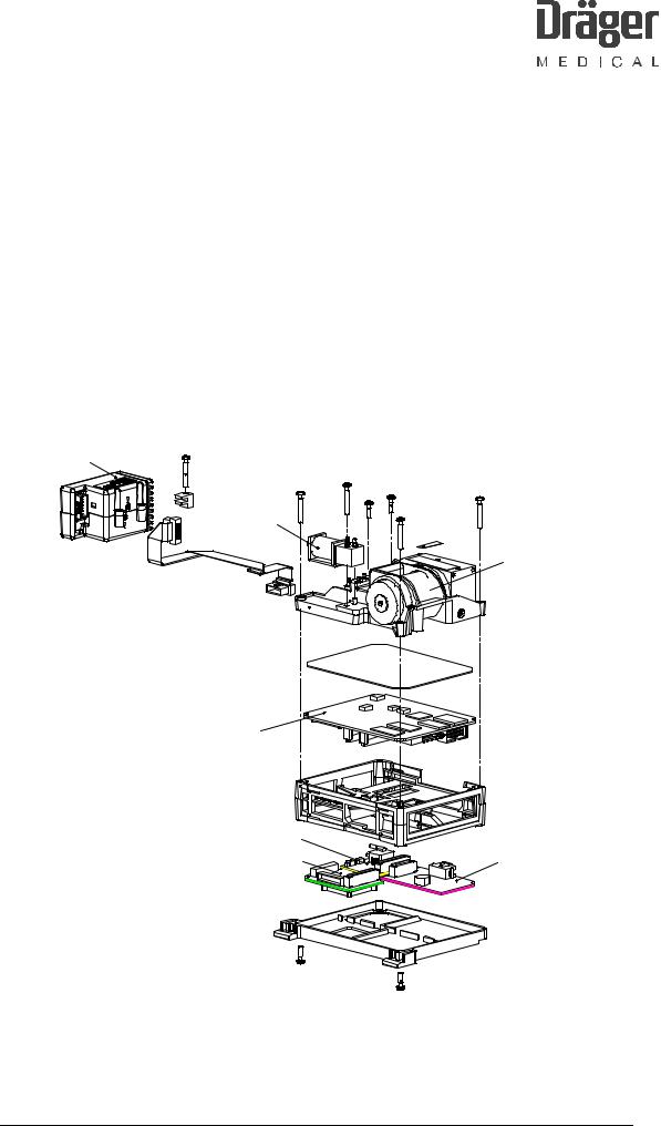
3.1Patient gas module structure
The ILCA patient gas module comprises the following components:
−Sensor head (electronics and optical system)
−Pump
−Valve
−AMO ILCA PCB (AMO = adapter for MOPS PCB)
−AMO FLOW ILCA PCB (flow controller)
−MOPS PCB (with PGM software, PGM = Patient Gas Module)
−AMO O2 GRAF PCB (with MFM software, MFM = Multi Function Module)
−PCB mounting frame
Sensor head
Valve
Pump
MOPS PCB |
|
Mounting frame |
|
AMO FLOW ILCA PCB |
|
AMO O2 GRAF PCB |
AMO ILCA PCB |
Fig. 4: Components of the ILCA module
6494.340 Vamos |
Version 3.0 |
Function Description |
14 |
F6494340T01.fm 21.08.02 |
All rights reserved. Copyright reserved. |
RETURN TO THIS MANUAL'S TABLE OF CONTENTS
RETURN TO CD-ROM TABLE OF CONTENTS
3.2Sensor head function
|
|
|
|
|
|
|
|
|
|
|
|
|
|
|
Light emitter |
|
|
|
|
|
|
|
|
|
|
|
|
|
|
|
|
|
|
|
|
|
|
|
||||||
|
|
|
|
|
|
|
|
|
|
|
|
|
|
|
|
|
|
|
|
|
|
|
|
|
|
|
|
|
|
|
|
|
|
|
|
|
|
|||||||
|
|
|
|
|
|
|
|
|
|
|
|
|
|
|
|
22 Hz _ _ |
|
|
|
|
|
|
|
|
|
|
|
|
|
|
|
|
|
|
|
|
|
|
|
|||||
|
|
|
|
|
|
|
|
|
|
|
|
|
|
|
|
|
|
|
|
|
|
|
|
|
|
|
|
|
|
|
|
|
|
|
|
|
|
|
|
|
|
|
|
|
|
|
|
|
|
|
|
|
|
|
|
|
|
|
|
|
|
|
|
|
|
|
|
|
|
|
|
|
|
|
|
|
|
|
NTC |
|
|
|
|
|
|
|
|
|
|
|
|
|
|
|
|
|
|
|
|
|
|
|
|
|
|
|
|
|
|
|
|
|
|
|
|
|
|
|
|
|
|
|
|
|
|
|
|
|
|
|
|
|
||
|
|
|
|
|
|
|
|
|
|
|
|
|
|
|
|
|
|
|
|
|
|
|
|
|
Heater (FET) |
|
|
|
|
|
|
|
|
|
||||||||||
|
|
|
|
|
|
|
|
|
|
|
|
|
|
|
|
|
|
|
|
|
|
|
|
|
|
|
|
|
|
|
|
|
|
|
|
|
||||||||
Patient |
|
|
|
|
|
|
|
|
|
|
|
|
|
|
|
|
|
|
|
|
|
|
|
|
|
|
|
|
|
|
|
|
|
|
|
|
|
|
|
|
|
|
|
|
|
|
|
|
|
|
|
|
|
|
|
|
|
|
|
|
|
|
|
|
|
|
|
|
|
|
|
|
|
|
|
|
|
|
|
|
|
|
|
|
|
|
|
||
gas |
|
|
|
|
|
|
|
|
|
|
|
|
|
|
|
Cuvette |
|
|
|
|
|
|
|
|
|
|
|
|
|
|
|
|
|
|
|
|
|
|
|
|||||
|
|
|
|
|
|
|
|
|
|
|
|
|
|
|
|
|
|
|
|
|
|
|
|
|
|
|
|
|
|
|
|
|
|
|
|
|
|
|
|
|
|
|
||
|
|
|
|
|
|
|
|
|
|
|
|
|
|
|
|
|
|
|
|
|
|
|
|
|
|
|
|
|
|
|
|
|
|
|
|
|
|
|
|
|
|
|
|
|
|
|
|
|
|
|
|
|
|
|
|
|
|
|
|
|
|
|
|
|
|
|
|
|
|
|
|
|
|
|
|
|
|
|
|
|
|
|
|
|
|
|
|
|
|
|
|
|
|
|
|
|
|
|
|
|
|
|
|
|
|
|
|
|
|
|
|
|
|
|
|
|
|
|
|
|
|
|
|
|
|
|
|
|
|
|
|
|
|
|
|
|
|
|
|
|
|
|
|
|
|
|
|
|
|
|
|
|
|
|
|
|
|
|
|
|
|
|
|
|
|
|
|
|
|
|
|
|
|
|
|
|
|
|
|
|
|
|
|
|
|
|
|
|
|
|
|
|
|
|
|
|
|
|
|
|
|
|
|
|
|
|
|
|
|
|
|
|
|
Pressure |
|
|
|
|
|
|
|
|
||
|
|
|
|
|
|
|
|
|
|
|
|
|
|
|
|
|
|
|
|
|
|
|
|
|
|
|
|
|
|
|
|
|
|
sensor |
|
|
|
|
|
|
|
|
||
|
|
|
|
|
|
|
|
|
|
|
|
ILCA |
|
|
|
|
|
|
|
|
|
|
|
|
|
|
|
|
|
|
|
|
|
|
|
|
|
|
|
|||||
|
|
|
|
|
|
|
|
|
|
|
|
Sensor |
|
|
|
|
|
|
|
|
|
|
|
|
|
|
|
|
|
|
|
|
|
|
|
|
|
|
|
|
||||
|
|
|
|
|
|
|
|
|
|
|
|
|
|
|
|
|
|
|
|
|
|
|
|
|
|
|
|
|
|
|
|
|
|
|
||||||||||
|
|
|
|
|
|
|
|
|
|
|
|
head |
|
|
|
|
|
|
|
|
|
|
|
|
|
|
|
|
|
|
|
|
|
|
|
|
|
|
|
|
||||
|
|
|
|
|
|
|
|
|
|
|
|
|
|
|
|
|
|
|
|
|
|
|
|
|
|
|
|
|
|
|
|
|
|
|
|
|
|
|
|
|
|
|
||
|
|
|
|
|
|
|
|
|
|
|
|
|
|
|
|
|
|
|
|
|
|
|
|
|
|
|
|
|
|
|
|
|
|
|
|
|
|
|
|
|
|
|
|
|
|
|
|
|
|
|
|
|
|
|
|
|
|
|
|
|
|
|
|
4-channel |
|
|
|
|
|
|
|
|
|
|
|
|
|
|
|
|
|
|
|
|
|
|
|||
|
|
|
|
|
|
|
|
|
|
|
|
|
|
|
|
|
|
|
|
detector |
|
|
|
|
|
|
|
|
|
|
|
|
|
|
|
|
|
|
|
|
PCB |
|
||
|
|
|
|
|
|
|
|
|
|
|
|
VV PCB |
|
|
|
|
|
|
|
|
|
|
|
|
|
|
|
|
|
|
|
|
|
|
|
|
|
|
||||||
|
|
|
|
|
|
|
|
|
|
|
|
|
|
|
|
|
|
|
|
|
|
|
|
|
|
|
|
|
|
|
|
|
||||||||||||
|
|
|
|
|
|
|
|
|
|
|
(Pre-amplifier) |
|
|
1st pre- |
|
|
|
|
|
|
|
|
|
|
|
|
|
|
|
|
|
|
|
|
ILCA |
|
||||||||
|
|
|
|
|
|
|
|
|
|
|
|
|
|
|
|
|
|
|
|
amplifier |
|
|
|
|
|
|
|
|
|
|
|
|
|
|
|
|
|
|
|
|
|
|||
|
|
|
|
|
|
|
|
|
|
|
|
|
|
|
|
|
|
|
|
|
|
|
|
|
|
|
|
|
|
|
|
|
|
|
|
|
|
|
|
|
|
|
AMO |
|
|
|
|
|
|
|
|
|
|
|
|
|
|
|
|
|
|
|
|
|
|
|
|
|
|
|
|
|
|
|
|
|
|
|
|
|
|
||||||||
|
|
|
|
|
|
|
|
|
|
|
|
|
|
|
|
|
|
|
|
|
|
|
|
|
|
|
|
|
|
|
|
|
|
|
|
|
|
|
|
|
|
|
||
|
|
|
|
|
|
|
|
|
|
|
|
|
|
|
|
|
|
|
|
|
|
|
|
|
|
|
|
|
|
|
|
|
|
|
|
|
|
|||||||
|
|
|
|
BASE PCB |
|
|
|
|
|
|
|
|
|
|
|
|
Light emitter |
|
|
|
|
|
|
|
|
|
||||||||||||||||||
|
|
|
|
|
|
|
|
|
|
|
|
|
|
|
|
|
|
|
|
|
|
|
|
|
|
|
|
|
|
|
|
|
|
|
|
|
|
|
|
|||||
|
|
|
|
|
|
|
|
|
|
|
|
|
|
|
|
|
|
|
|
|
|
|
|
|
|
|
|
|
|
|
|
|
|
|
|
|
|
|
|
|||||
|
|
|
|
|
|
|
|
|
|
|
|
|
|
|
|
|
|
|
|
|
|
|
|
|
|
|
|
|
|
|
|
|
control |
|
|
|
|
|
|
|
|
|
||
|
|
|
|
|
|
|
|
|
|
|
|
|
|
|
|
|
|
|
|
|
|
|
|
|
|
|
|
|
|
|
|
|
|
|
|
|
|
|
|
|
|
|||
|
|
|
|
|
|
|
|
|
|
|
|
|
|
|
|
|
|
|
|
2nd pre- |
|
|
|
|
|
|
|
|
|
|
(AMO ILCA |
|
|
|
|
|
|
|
|
|
|
|||
|
|
|
|
|
|
|
|
|
|
|
|
|
|
|
|
|
|
|
|
|
|
|
|
|
|
|
|
|
|
|
|
|
|
|
|
|
|
|
|
|||||
|
|
|
EEPROM |
|
|
|
|
|
|
|
|
amplifier |
|
|
|
|
|
|
|
|
|
|
|
|
|
|
|
|
|
|
|
|
||||||||||||
|
|
|
|
|
|
|
|
|
|
|
|
|
|
|
|
|
|
|
PCB) |
|
|
|
|
|
|
|
|
|
|
|||||||||||||||
|
|
|
|
|
|
|
|
|
|
|
|
|
|
|
|
|
|
|
|
|
|
|
|
|
|
|
|
|
|
|
|
|
|
|
|
|
|
|
|
|
|
|
||
|
|
|
|
|
|
|
|
|
|
|
|
|
|
|
|
|
|
|
|
|
|
|
|
|
|
|
|
|
|
|
|
|
|
|
|
|
|
|
|
|
|
|
|
|
|
|
|
|
|
|
|
|
|
|
|
|
|
|
|
|
|
|
|
|
|
|
|
|
|
|
|
|
|
|
|
|
|
|
|
|
|
|
|
|
|
|
|
|
|
|
|
|
|
|
|
|
|
|
|
|
|
|
8-channel |
multiplexer |
|
|
|
|
|
|
|
|
|
|
Pressure |
|
|
|
|
|
|
|
|
|||||||||||
|
|
|
|
|
|
|
|
|
|
|
|
|
Track & Hold |
|
|
|
|
|
|
|
|
|
|
|
|
|
|
|
|
|
|
|||||||||||||
|
|
|
|
|
|
|
|
|
|
|
|
|
|
|
|
|
|
|
|
|
|
|
|
|
|
|
|
|
|
|
|
|
|
|
||||||||||
|
|
|
|
|
|
|
|
|
|
|
|
8-channel A/D converter |
|
|
|
|
|
|
|
|
|
|
|
|
|
|
|
|
|
|
|
|
|
|
||||||||||
|
|
Temperature |
|
|
|
measurement |
|
|
|
and control |
Data |
|
|
|
|
Control signals |
Data |
|
Control signals |
|
|
MOPS PCB
Fig. 5: Sensor head block diagram
6494.340 Vamos |
Version 3.0 |
Function Description |
15 |
RETURN TO THIS MANUAL'S TABLE OF CONTENTS
RETURN TO CD-ROM TABLE OF CONTENTS
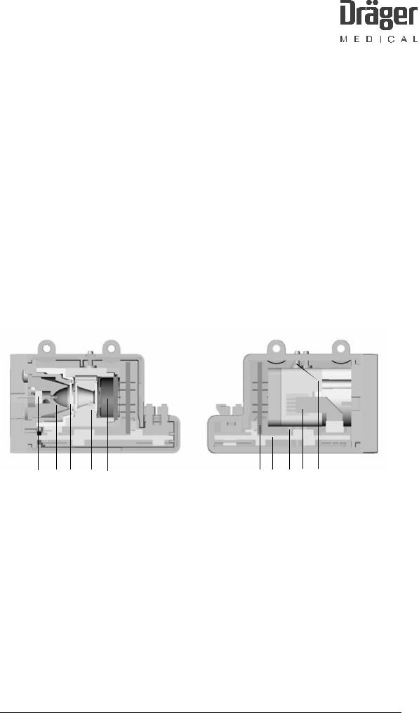
The hardware of the ILCA sensor head comprises the following three PCBs:
VV PCB: − 1st amplifier for all channels of the four-channel detector including high/low pass combinations and EMC configurations.
BASE PCB:
AMO ILCA PCB
−2nd amplifier for all channels of the four-channel detectorLight emitter actuation, temperature control, absolute pressure measurement, AD converter, multiplexer, serial EEPROM.
−Generation of the supply voltages
−Digitally adjustable voltage for the light emitter via the MOPS PCB.
−Heating voltage
−Supply to ILCA
−and setpoint setting for the sensor head heating (digital potentiometer).
−Data transport: ILCA sensor ↔ MOPS PCB for data evaluation
F6494340T01.fm 21.08.02 |
All rights reserved. Copyright reserved. |
1 |
2 |
3 |
4 |
5 |
6 |
7 |
8 |
9 |
10 |
Fig. 6: Sensor head, sectional view
Key to sensor head sectional view |
|
|
|
1 |
Light emitter (infrared range) |
6, 7 |
PCBs |
2 |
Reflector |
8 |
Cuvette heating (FET) |
3 |
CaF2 disc of light emitter |
9 |
Pressure sensor |
4 |
Cuvette |
10 |
Cuvette inlet and outlet |
5 |
Multispectrum detector |
|
|
6494.340 Vamos |
Version 3.0 |
Function Description |
16 |

RETURN TO THIS MANUAL'S TABLE OF CONTENTS
RETURN TO CD-ROM TABLE OF CONTENTS
3.2.1Light emitter with reflector
The reflector is ellipsoid in shape. The light emitter is positioned at the vertex of the ellipsoid. As a result, a beam is directed at an angle of incidence of < 12° onto the opposite detector.
The emitting element of the light emitter is a filament made of resistor wire. The alloy comprises Cr, Ni, Al. The filament wire is 40 µm thick.
In the assembled sensor, the reflector with built-in light emitter is encapsulated away from the interior of the sensor head by a CaF2 disc. This design prevents sampling gas from reaching the hot light emitter, and igniting oxygen and the anesthetic, in the event of a leak in the cuvette. Furthermore, any gaseous substances emitted by the hot light emitter are kept away from the cuvette. This avoid an undesired coating on the optical components as a result of prolonged use.
3.2.2Light emitter specification
Cold resistance Rc = 13.0 ohms ± 11%
Hot resistance Rh = 13.0 ohms * 1.06 = 13.78 ohms ±11%
Peak output = 290 mA * 290 mA * 13.78 ohms = 1.16 W
3.2.3Light emitter control circuit
The light emitter is operated with a square-wave modulated constant current of 290 mA at 22.0 Hz.
This light emitter current is measured with an AD converter (shunt resistor 0.5 ohms ± 2%) and monitored by the software of the MOPS PCB.
The supply voltage of the light emitter control circuit is also monitored by AD converter and voltage divider. The setpoint is set via a digital serial potentiometer controlled by the MOPS PCB.
The supply voltage is measured when the light emitter is off (low phase of light emitter modulation).
F6494340T01.fm 21.08.02 |
All rights reserved. Copyright reserved. |
6494.340 Vamos |
Version 3.0 |
Function Description |
17 |

F6494340T01.fm 21.08.02 |
All rights reserved. Copyright reserved. |
RETURN TO THIS MANUAL'S TABLE OF CONTENTS
RETURN TO CD-ROM TABLE OF CONTENTS
3.2.4Light emitter protection circuits
When the connection between the MOPS PCB and the BASE PCB is interrupted, a protection circuit immediately shuts down the light emitter.
A protection circuit also prevents the average light emitter current from exceeding 81 mA (tolerance = 3%) in the event of a fault (e.g. software crash). The response time (tA) of the protection circuit is 65 ms ± 15 ms. This condition applies when the light emitter was previously off and is then switched to continuous current.
3.2.5Cuvette
Notice:
Do not generate an excess pressure in the cuvette.
The sampling gas is routed through a cuvette in the sensor head. In the optical beam path it is sealed on each side by a bonded-in CaF2 glass window pane. The gas inlet and outlet form the two connectors. The direction of flow of the sampling gas is indicated by arrows on the housing adjacent to the connectors.
For absorption reasons the distance between the light emitter window and the detector window is 6 mm.
3.2.6Multispectrum detector
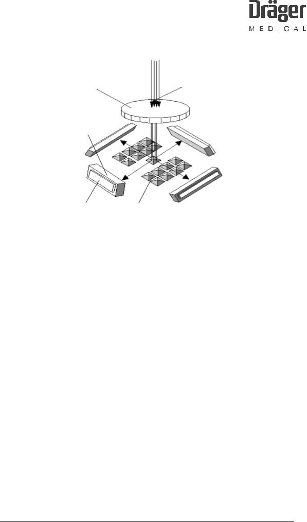
In the multispectrum detector the optical beam path is distributed across the four measuring channels and routed to the relevant detector chip by infrared narrow-band filters.
The optical beam enters the multispectrum detector through a hermetically sealed window. On the floor of its housing is a matrix-style array of four-sided reflective pyramids with a side length of 0.15 mm x 0.15 mm (beam splitters). The optical beam entering through the window hits this beam splitter and is split by each individual pyramid in pixel style into four separate beams. The pixel-style design results in a genuine beam mix, which is insensitive to partial contamination in the beam path. The housing also contains four infrared optical narrow-band filters and four pyroelectric detector chips. These components are arranged such that one infrared filter detector combination is illuminated by each of the four beam paths emitted from the beam splitter. Each of the four beam paths represents a measuring channel. The basic design of the multispectrum detector is shown in the following diagram:
6494.340 Vamos |
Version 3.0 |
Function Description |
18 |
RETURN TO THIS MANUAL'S TABLE OF CONTENTS RETURN TO CD-ROM TABLE OF CONTENTS
F6494340T01.fm 21.08.02 |
All rights reserved. Copyright reserved. |
|
|
|
|
|
Light beams |
Sensor window |
||
|
|
|
Infrared filter
CO2
N2O
Anesth. gas
Ref.
|
|
|
|
Sensor chip |
|||
|
Beam splitter |
||
|
|
|
Fig. 7: Basic design of the multispectrum detector
The infrared optical filters (band-pass filters) are dimensioned in terms of their wavelength such that light is transmitted in three channels at the wavelength of the sampled gases. The remaining spectrum is blocked by these three filters. When a gas is present light is absorbed and the resultant change of intensity measured in the respective channel is a measure of the concentration of the gas.
The fourth channel (reference channel) measures at a wavelength at which none of the sampled gases absorbs. With the reference signal, ambient influences such as temperature fluctuations, cuvette contamination, and light emitter aging are compensated and corrected.
The detector elements and the upstream filters are tilted 30°. As a result, the reflected beam strikes perpendicular to the filter plane and the detector plane.
3.2.7Pressure sensor
The ILCA sensor head delivers its measured values as partial pressures or as the non-pressure-dependent unit vol.%. Fluctuations in cuvette pressure have no effect on the measured values. An absolute pressure sensor measures the pressure in the cuvette and, where appropriate, the ambient pressure (e.g. during zeroing).
The pressure measurement is fast enough to represent fluctuations in respiratory pressure (T90 better than 200 ms).
6494.340 Vamos |
Version 3.0 |
Function Description |
19 |

F6494340T01.fm 21.08.02 |
All rights reserved. Copyright reserved. |
RETURN TO THIS MANUAL'S TABLE OF CONTENTS
RETURN TO CD-ROM TABLE OF CONTENTS
Measuring range:
The sensor head is able to measure at ambient pressures between 670 mbar and 1100 mbar. For the measuring range of the pressure sensor it should be considered that the pressure in the cuvette may be as much as 200 mbar below ambient pressure (vacuum in the suction system).
3.2.8Sensor heating (FET)
An insulated power FET which is screwed onto the cuvette is used for temperature stabilization of the cuvette (setpoint temperature 58 °C). The drain source resistor of the FET is controlled via a control voltage and is used as sensor heating. The current that flows through the FET determines the heating output with the voltage drop across the FET.
The setpoint of the temperature is specified by the MOPS software. The microcontroller on the MOPS PCB control a digital potentiometer located on the AMO ILCA PCB power module. Its output voltage is routed to the FET via an impedance converter. The temperature is monitored by an NTC.
3.2.9Memory for calibration data
All calibration data, serial numbers, and settings required to operate the sensor head are stored in an EEPROM on the Base PCB in the sensor head.
3.3Sensor head operation
The sensor head attains its full accuracy when it has reached its operating temperature and a stable temperature distribution. The time from power-on until ready-to-measure is determined by the duration of the warm-up phase. The warm-up phase is dependent on the temperature distribution when the sensor is powered up. The sensor software optimizes the starting behavior. In the worst case the sensor head attains its specified accuracy no later than 4 minutes after power-on.
3.3.1Self test
The sensor head software performs a self-test when the system starts up and continuously during measurement operation. In the event of an error the sensor software generates the relevant status message and shuts down the system if necessary.
6494.340 Vamos |
Version 3.0 |
Function Description |
20 |
RETURN TO THIS MANUAL'S TABLE OF CONTENTS
RETURN TO CD-ROM TABLE OF CONTENTS
3.3.2Zeroing
The measurement signals of the sensor head may drift over a lengthy period in operation (due to aging, temperature fluctuations, etc.). Contamination of the cuvette can also impair signal intensity. Consequently, a reset to zero is performed on completion of the warm-up phase and then every 2 hours. Ambient air (as reference gas) is present in the cuvette during zeroing.
During operation, system states may occur (such as sudden contamination of the cuvette) which necessitate an additional zeroing. The sensor software detects such states automatically.
3.4Measured value units
The measured values of the ILCA sensor head are produced from the measured values in the cuvette. There is no conversion to the conditions at other points in the system, such as in the Y-piece or the patient’s lung.
3.4.1General remarks on the concentration figures
The concentration of the anesthetics is calculated by referencing the measured partial pressures of the gas components to the overall pressure in the cuvette.
The concentrations can be scaled in two different ways. As a physical unit, the standard representation is in percent by volume [vol.%], i.e. referred to 100%.
Conversely, for some gases medical experts apply a reference to 760 Torr. This figure in a pressure unit is not a pressure, however, but a concentration, and must not be confused with a partial pressure!
The concentrations are converted from vol.% to Torr as follows:
100 Vol.% = 760 "Torr"
1 vol.% * (760 /100 Torr/vol.%) = 7.6 Torr
1 Torr * (100/760 vol.%/Torr) = 0.1316 vol.%
It is essential that this conversion of the concentrations should be distinguished from conversion of the pressures!
F6494340T01.fm 21.08.02 |
All rights reserved. Copyright reserved. |
6494.340 Vamos |
Version 3.0 |
Function Description |
21 |
F6494340T01.fm 21.08.02 |
All rights reserved. Copyright reserved. |
RETURN TO THIS MANUAL'S TABLE OF CONTENTS
RETURN TO CD-ROM TABLE OF CONTENTS
3.5Pneumatic system
Ambient air |
Sintered filter |
|
||
|
|
|
||
Valve |
R2 |
|
C1 damper |
|
|
(buffer volume) |
|||
MOPS PCB |
||||
|
|
|||
|
|
R1 |
air |
|
135 mL |
|
Ambient |
||
Teflon |
P |
|
|
|
tube |
ILCA |
|
|
|
|
|
|
||
|
|
P |
|
|
15 mL |
|
|
Diaphragm pump |
|
Sampling gas |
|
AMO FLOW ILCA PCB |
||
|
|
|||
Fig. 8: ILCA pneumatics diagram
The pneumatic system of the ILCA module comprises the following components:
−A DC diaphragm pump
−A valve
−An "AMO FLOW ILCA PCB"
−A pneumatic low-pass filter, at least one filter, and the associated anestheticresistant tubing
−A water trap and a Teflon hose
3.6Tubing
The pressure surges generated by the pump are minimized by a pneumatic low-pass filter consisting of a restrictor (R1) and a damper (C1). These components are mounted in the module housing of ILCA.
Dimensioning of R1:
R1 is small enough for the pump not to be placed under unnecessary strain. However, an inadequate input load may make it impossible to set the target flow of 150 mL/min.
R1 is large enough so that the pressure surges occurring in the cuvette do not impair the signal ratio and noise ratio in gas sampling.
6494.340 Vamos |
Version 3.0 |
Function Description |
22 |

RETURN TO THIS MANUAL'S TABLE OF CONTENTS
RETURN TO CD-ROM TABLE OF CONTENTS
Dimensioning of R2:
In a zeroing operation, the valve switchover is also tested based on the pressure drop. In this case the pressure drop via the restrictor R2 and the ambient air filter is significantly less than the minimum pressure drop via the water trap and the suction tubing to the patient.
3.7Pump
The pump flow is 150 mL/min ± 20 mL/min. The supply voltage is in the range from 2.5 V to 7.5 V DC at a current of up to 150 mA.
F6494340T01.fm 21.08.02 |
All rights reserved. Copyright reserved. |
6494.340 Vamos |
Version 3.0 |
Function Description |
23 |
F6494340T01.fm 21.08.02 |
All rights reserved. Copyright reserved. |
RETURN TO THIS MANUAL'S TABLE OF CONTENTS
RETURN TO CD-ROM TABLE OF CONTENTS
3.8MOPS PCB
Components (ILCA, AMO FLOW ILCA PCB, etc.)
Component ports |
|
|
V |
Distribution across ports |
Voltages 6.4V, V, 15 |
||
|
|
||
|
|
|
5 |
ASIC |
A/D |
PCB voltages |
Module voltages 15 VDC (ILCA) |
|
switch |
|
|
I/O EEPROM TPU CS Addr. Data |
|
RAM |
Flash EPROM |
|
Motorola 68332 |
SCI |
Electrical isolation |
RS232 |
Supply voltage |
MOPS PCB
VAMOS PCB
Fig. 9: Block diagram, MOPS PCB
6494.340 Vamos |
Version 3.0 |
Function Description |
24 |

RETURN TO THIS MANUAL'S TABLE OF CONTENTS
RETURN TO CD-ROM TABLE OF CONTENTS
“"MOPS" stands for "Modular Platform for Sensors". A modular concept by which suitable sensor components (pneumatic and mechanical components) can be operated together by way of a processor board. The resultant arrangements are operated by a software program with a unified communications interface. In this way, the user is provided with a uniform view of the measurement parameters on offer, irrespective of the components deployed. The software is automatically configured for the connected components when the system starts up.
With this concept, different gas sampling modules (for example ILCA and IRIA) can be configured for specific customer needs using standard components.
The MOPS PCB calculates values of the patient parameters and controls the sensor head signals.
F6494340T01.fm 21.08.02 |
All rights reserved. Copyright reserved. |
6494.340 Vamos |
Version 3.0 |
Function Description |
25 |
F6494340T01.fm 21.08.02 |
All rights reserved. Copyright reserved. |
RETURN TO THIS MANUAL'S TABLE OF CONTENTS
RETURN TO CD-ROM TABLE OF CONTENTS
3.9AMO FLOW ILCA PCB (flow controller)
|
|
|
|
|
|
|
ILCA |
|
|
|
|
|
PCB |
|
|
|
|
|
Flow |
|
|
|
|
|
ILCA |
regulatorwith digital potentiometer (pressuresensor calibrationand pump voltage). |
|
|
|
|
AMOLP |
|
|
|
|
|
AMOFLOW |
Pumpcurrent and voltage measurement |
|
|
|
|
|
Valve control |
EEPROM |
||
|
|
Switching |
|
|
|
|
|
|
|
|
|
Pump |
|
∆P sensor |
∆P amplifier |
|
Sintered- C1: Damper |
R1 |
|
Offset calibration |
Differential pressure |
ILCA cuvette
MOPS PCB connector
digital and analog signals

|
P Absolute |
pressure sensor |
bypass |
Valve |
|
|
Water trap |
|
R2 |
|
|
Filter |
WAL |
|
|
Ambient air |
Patient |
Fig. 10: Connection diagram, AMO FLOW ILCA PCB
6494.340 Vamos |
Version 3.0 |
Function Description |
26 |

RETURN TO THIS MANUAL'S TABLE OF CONTENTS
RETURN TO CD-ROM TABLE OF CONTENTS
The AMO FLOW ILCA PCB controls the pump and the valves of ILCA. The PCB is controlled and powered by the MOPS PCB. The actual regulation of the pump flow is handled by the software of the controller on the MOPS PCB.
The "AMO FLOW ILCA PCB" holds the following components:
−A DC/DC converter generates the pump voltage (2.5 - 7.5 V/DC). The output voltage of the DC/DC converter is controlled through a serial digital potentiometer on the PCB and set by the controller of the MOPS PCB.
−Analog electronics for evaluation of the pump voltage, pump current, valve current, and differential pressure.
−The power output elements of the valves.
−Service LEDs for the pump voltage, the valves, and the supply voltage.
−A temperature-compensated differential pressure sensor for flow metering. The sensor offset is corrected with a serial digital potentiometer.
The flow is measured by way of the differential pressure of restrictor R1 plus the upstream sintered-metal filter. The measuring range is 0 to 350 mbar.
The AMO FLOW ILCA PCB is connected directly to a 60-pin connector on the MOPS PCB and is detected automatically by the MOPS PCB.
3.9.1EEPROM of AMO FLOW ILCA PCB
The serial EEPROM contains the following information:
−Serial Number
−Hardware revision
−Software revision
−Product name (AMO FLOW ILCA PCB)
−Control parameters
−Position of the digital potentiometer at which the differential pressure output DIFFDRUCK = 2.0 V
−The voltage setpoint value at which the flow is 150 mL/min
−OCCLUDED detection value
F6494340T01.fm 21.08.02 |
All rights reserved. Copyright reserved. |
6494.340 Vamos |
Version 3.0 |
Function Description |
27 |

RETURN TO THIS MANUAL'S TABLE OF CONTENTS
RETURN TO CD-ROM TABLE OF CONTENTS
3.9.2Safety concept
The following voltages are routed via the AD converter of the MOPS PCB to the switch-mode regulator in order to monitor limits and regulate the flow:
−the differential pressure
−the pump voltage
−a voltage proportional to the pump current
−a voltage proportional to the total valve current
3.9.3Valve
The valve at X4 switches between ambient air and patient air. An optional valve at X5 is possible (is not mounted in VAMOS).
The valve is non-polarized. There is no preferred position for the plug connector. A mechanical lock prevents the valves from detaching from the connector.
F6494340T01.fm 21.08.02 |
All rights reserved. Copyright reserved. |
6494.340 Vamos |
Version 3.0 |
Function Description |
28 |
F6494340T01.fm 21.08.02
All rights reserved. Copyright reserved.
.6494 |
.Fig |
|
Vamos340 |
Block11: |
|
+ 5 V power supply |
||
|
diagram, |
Power supply |
|
(10...16.5 V) |
|
0.3Version |
O2AMO |
Voltage monitoring |
Synchronous serial |
||
|
|
communication with |
|
|
the processor of the |
|
GRAF |
AMO O2 GRAF PCB |
|
Synchronous serial |
|
|
PCB |
communication with |
|
the EEPROM on the |
|
Function |
|
AMO O2 GRAF PCB |
|
Reset of the |
|
Description |
|
processor of the |
|
AMO O2 GRAF PCB |
|
|
|
|
Interface to the
MOPS PCB
29
+ 5 V)
Shut-off
EEPROM
|
|
|
|
|
|
|
|
|
|
|
RS 232 |
|
|
|
Reset controller |
|
Driver |
|
||
|
|
|
|
|
|
|
|
|
|
|
|
|
|
|
|
|
|
|
|
|
Processor
Oscillator 32 kHz
FLASH EPROM
SRAM
Debug interface (service BD32)
AMO LPO2AMOGRAFO2-PCBGraf Rev. 02
+ 5 V) Asynchronous serial communication
Interface to the
VAMOS PCB
Control: Display unit Keypad LEDs Control knob Fan control Alarm/signal tones
Charging/battery control SpO2 module
Interface to the
VAMOS PCB
PCB GRAF O2 AMO 4
CONTENTS OF TABLE MANUAL'S THIS TO RETURN CONTENTS OF TABLE ROM-CD TO RETURN

RETURN TO THIS MANUAL'S TABLE OF CONTENTS
RETURN TO CD-ROM TABLE OF CONTENTS
On the AMO O2 GRAF PCB the screen data are processed by a co-processor. The PCB controls and monitors the complete monitor function including the keypad, control knob, indicator lamps (LEDs), and SpO2 sensors.
F6494340T01.fm 21.08.02 |
All rights reserved. Copyright reserved. |
6494.340 Vamos |
Version 3.0 |
Function Description |
30 |
 Loading...