


Technical Documentation
Zeus
Anesthetic workstation
Revision 3.0 5133.001 9036190
Because you care

K5133001IECIVZ.fm 03.05.06 |
All rights reserved. Copyright reserved. |
Contents
General
1 |
Symbols and Definitions |
3 |
2 |
Notes |
3 |
3 |
Abbreviations and Definitions |
5 |
Function Description
1 |
General information about Zeus |
9 |
|
|
1.1 |
Intended use (summary from the Instructions for Use manual) |
............................................. 9 |
|
1.2 |
Product classification .............................................................................................................. |
9 |
|
1.3 |
Protection classes .................................................................................................................. |
9 |
|
1.4 |
Brief description of the system ............................................................................................. |
10 |
2 |
Anaesthetic Gas Box |
13 |
|
|
2.1 |
General introduction ............................................................................................................. |
13 |
3 |
PCB Box |
15 |
|
|
3.1 |
DIANA PCB .......................................................................................................................... |
15 |
|
3.2 |
VERONA PCB ...................................................................................................................... |
16 |
|
3.3 |
Vent Power PCB ................................................................................................................... |
18 |
|
3.4 |
External Flow PCB ............................................................................................................... |
19 |
4 |
CS Module |
23 |
|
|
4.1 |
Purpose ................................................................................................................................ |
23 |
|
4.2 |
Gas supply ........................................................................................................................... |
23 |
|
4.3 |
DAGMAR mixed gas metering unit ...................................................................................... |
26 |
5 |
DIVA Anaesthetic Metering Unit |
29 |
|
|
5.1 |
General introduction ............................................................................................................. |
29 |
|
5.2 |
DIVA supply module ............................................................................................................. |
30 |
I

Contents
|
5.3 |
DIVA metering module .......................................................................................................... |
33 |
6 |
Zeus Gas Measuring Module (GMZ) |
39 |
|
|
6.1 |
General introduction ............................................................................................................. |
39 |
7 |
Patient Gas Analyzer (PGA) |
41 |
|
|
7.1 |
General ................................................................................................................................. |
41 |
|
7.2 |
IRIA ....................................................................................................................................... |
41 |
|
7.3 |
ILCA 2 ................................................................................................................................... |
43 |
|
7.4 |
Servomex or Pato ................................................................................................................ |
44 |
8 |
System Gas Analyser (SGA) |
49 |
|
|
8.1 |
General introduction ............................................................................................................. |
49 |
|
8.2 |
ILCA ...................................................................................................................................... |
50 |
|
8.3 |
OxyTrace .............................................................................................................................. |
54 |
9 |
Power supply unit |
57 |
|
|
9.1 |
General ................................................................................................................................. |
57 |
|
9.2 |
Mains power input ................................................................................................................ |
57 |
|
9.3 |
Output voltages ..................................................................................................................... |
58 |
|
9.4 |
Uninterruptible power supply ................................................................................................ |
59 |
10 |
Dräger Water Trap |
61 |
|
11 |
Blower |
63 |
|
|
11.1 |
General introduction ............................................................................................................. |
63 |
|
11.2 |
Function ................................................................................................................................ |
63 |
12 |
Breathing System |
67 |
|
|
12.1 |
General introduction ............................................................................................................. |
67 |
|
12.2 |
Components in the breathing system and their functions .................................................... |
68 |
|
12.3 |
Function ................................................................................................................................ |
70 |
All rights reserved. Copyright reserved. |
K5133001IECIVZ.fm 03.05.06 |
II

|
|
Contents |
13 Hermes Computer with Monitor |
73 |
|
13.1 |
General ................................................................................................................................. |
73 |
13.2 |
CPCI computer ..................................................................................................................... |
73 |
13.3 |
Display screen ...................................................................................................................... |
74 |
K5133001IECIVZ.fm 03.05.06 |
All rights reserved. Copyright reserved. |
Maintenance Procedures
1 |
Water trap |
79 |
|
|
1.1 |
Replacement interval ............................................................................................................ |
79 |
|
1.2 |
Replacing or draining the water trap .................................................................................... |
79 |
2 |
Blower spindle |
81 |
|
|
2.1 |
Replacement interval ............................................................................................................ |
81 |
|
2.2 |
Replacing the blower spindle ............................................................................................... |
81 |
3 |
Filter mat in the power supply unit |
83 |
|
|
3.1 |
Replacement interval ............................................................................................................ |
83 |
|
3.2 |
Location ................................................................................................................................ |
83 |
|
3.3 |
Removing the cover ............................................................................................................. |
83 |
|
3.4 |
Replacing the filter mat ......................................................................................................... |
83 |
4 |
Filter mat in the GMZ |
85 |
|
|
4.1 |
Replacement interval ............................................................................................................ |
85 |
|
4.2 |
Replacing the filter mat ......................................................................................................... |
85 |
5 |
Removing/fitting the breathing system |
87 |
|
6 |
Diaphragm mounts in the breathing system |
89 |
|
|
6.1 |
Replacement interval ............................................................................................................ |
89 |
|
6.2 |
Removing the breathing system ........................................................................................... |
89 |
|
6.3 |
Replacing the diaphragm mount .......................................................................................... |
89 |
|
6.4 |
Fitting the breathing system ................................................................................................. |
91 |
III

Contents
7 |
Flow sensor “SpiroLife” in the breathing system |
93 |
|
|
7.1 |
Replacement interval ............................................................................................................ |
93 |
|
7.2 |
Replacing the “SpiroLife” flow sensor ................................................................................... |
93 |
8 |
Sampling-gas return-line filter |
95 |
|
|
8.1 |
Replacement interval ............................................................................................................ |
95 |
|
8.2 |
Replacing the filter ................................................................................................................ |
95 |
9 |
Sintered-metal filters of the CS connections |
97 |
|
|
9.1 |
Replacement interval ............................................................................................................ |
97 |
|
9.2 |
Replacing the sintered-metal filters ...................................................................................... |
97 |
10 |
Pressure regulators on the gas inlet block |
99 |
|
|
10.1 |
Replacement interval ............................................................................................................ |
99 |
|
10.2 |
Location ................................................................................................................................ |
99 |
|
10.3 |
Disassembly ......................................................................................................................... |
99 |
|
10.4 |
Replacing the pressure regulators ...................................................................................... |
102 |
11 |
Batteries of the uninterruptible power supply |
105 |
|
|
11.1 |
Replacement interval .......................................................................................................... |
105 |
|
11.2 |
Location .............................................................................................................................. |
105 |
|
11.3 |
Replacing the rechargeable batteries ................................................................................. |
105 |
All rights reserved. Copyright reserved. |
K5133001IECIVZ.fm 03.05.06 |
IV

Contents
Schematics and Diagrams
1 |
Schematics and diagrams |
109 |
Annex
Technical Documentation acc. to EMV standard IEC/EN 60601-1-2: 2001
Test List
Spare Parts Catalogue
K5133001IECIVZ.fm 03.05.06 |
All rights reserved. Copyright reserved. |
V

VI |
|
Contents |
|
|
|
All rights reserved. Copyright reserved.
K5133001IECIVZ.fm 03.05.06

General
1

2
Zeus |
General |
|
|
1Symbols and Definitions
WARNING
A WARNING statement provides important information about a potentially hazardous situation which, if not avoided, could result in death or serious injury.
CAUTION
A CAUTION statement provides important information about a potentially hazardous situation which, if not avoided, may result in minor or moderate injury to the user or patient or in damage to the equipment or other property.
NOTE
A NOTE provides additional information intended to avoid inconvenience during operation.
Definitions according to German standard DIN 31051:
Inspection |
= examination of actual condition |
|
Maintenance |
= measures to maintain specified condition |
|
Repair |
= |
measures to restore specified condition |
Servicing |
= |
inspection, maintenance, and repair |
2Notes
General Technical Documentation.fm |
|
Released Printed on 03.05.06 K5133001_ |
reserved. Copyright reserved. |
Version 3.0_ |
All rights |
This Technical Documentation conforms to the IEC 60601-1 standard.
Read each step in every procedure thoroughly before beginning any test. Always use the proper tools and specified test equipment. If you deviate from the instructions and/or recommendations in this Technical Documentation, the equipment may operate improperly or unsafely, or the equipment could be damaged.
It is our recommendation to use only Dräger parts and supplies.
The maintenance procedures described in this Technical Documentation may be performed by qualified service personnel only. These maintenance procedures do not replace inspections and servicing by the manufacturer.
The information in this Technical Documentation is confidential and may not be disclosed to third parties without the prior written consent of the manufacturer.
This Technical Documentation is for the purpose of information only. Product descriptions found in this Technical Documentation are in no way a substitute for reading and studying the Instructions for Use/Operating Manual enclosed with the product at the time of delivery.
5133.001 |
3 |

General |
Zeus |
|
|
Know-how contained in this Technical Documentation is subject to ongoing change through research and development and Dräger Medical reserves the right to make changes to this Technical Documentation without notice.
NOTE
Unless otherwise stated, reference is made to laws, regulations or standards (as amended) applicable in the Federal Republic of Germany for equipment used or serviced in Germany. Users or technicians in all other countries must verify compliance with local laws or applicable international standards.
|
Technical Documentation.fm |
|
General_ |
reserved. Copyright reserved. |
Released Printed on 03.05.06 K5133001_ |
All rights |
Version 3.0 |
4 |
5133.001 |

Zeus |
Function Description |
|
|
3Abbreviations and Definitions
Released Printed on 03.05.06 F5133001 abbreviations.fm |
reserved. Copyright reserved. |
Version 1.0_ |
All rights |
A-Box |
Anaesthetic Gas Box |
APL |
Adjustable Pressure Limit |
CAN |
Controller Area Network |
CPCI |
Compact Peripheral Component Interconnect |
DAGMAR |
Digital Advanced Gas Mixer for Anesthesia Require- |
|
ments |
DIANA |
DIgita ANaesthestic controller in A-Box |
DIVA |
Digital Injection of Volatile Agent |
DUMA |
Flowmeter for volatile anaesthetic |
DVI |
Digital Video Interface |
EEPROM |
Electrically Eraseable Programmable Read Only |
|
Memory |
Flash-ROM |
Flash Read Only Memory |
GMZ |
Gas Measuring module Zeus |
HERMES |
Display and operating unit of Zeus |
ILCA |
Infrared Low Cost Analyzer |
IRIA |
Infrared Rapidly Identifying Analyzer |
MIB |
Management Information Base |
MIR |
Mid Infrared Range |
MISO |
Master Input Slave Output |
MOSI |
Master Output Slave Input |
NIR |
Near Infrared Range |
PLD |
Programmable Logic Device |
PWM |
Pulse Width Modulation |
RAM |
Random Access Memory |
SDRAM |
Synchronous Dynamic RAM |
SNMP |
Simple Network Management Protocol |
SPI |
Serial Peripheral Interface |
SRAM |
Static RAM |
TFT |
Thin Film Transistor |
TIVA |
Total IntraVenous Anesthesia |
UART |
Universal Asynchronous Receiver/Transmitter |
USB |
Universal Serial Bus |
UPS |
Uninterruptible Power Supply |
Zeus |
Name of anaesthetic workstation |
5133.001 |
5 |

6 |
Function |
|
Description |
001.5133
All rights reserved. Copyright reserved.
Zeus
Version 1.0_ Released_Printed on_03.05.06_F5133001_abbreviations.fm

Function Description
7

8
Zeus |
General |
|
|
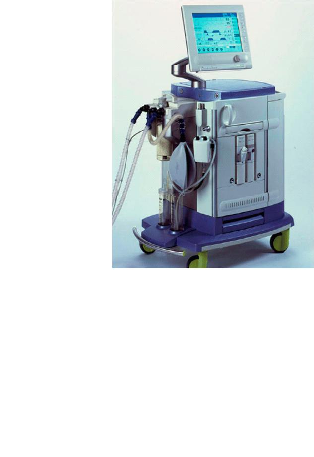
1General information about Zeus
Figure 1 View of the Zeus anesthesia workstation
1.1Intended use (sum- Zeus is an integrated anesthesia workstation for inhalation and intravenous
about.fm |
|
|
|
mary from the |
anesthesia. Zeus is used |
|
|
|
|
Instructions for Use |
– in operating rooms as well as in induction and recovery rooms |
||
|
|
|
|
|||
General_ |
|
|
|
manual) |
– with anesthetic agents Isoflurane, Sevoflurane and Desflurane |
|
|
|
|
|
|
– in adults, children and neonates |
|
ZEUS |
|
|
|
|
– with gas mixtures O2/AIR, O2/N2O |
|
onPrintedReleased03.05.06 F5133001 |
Copyrightreserved.reserved. |
1.3 |
Protection classes |
|||
Class I according to EN 60601-1. |
||||||
|
|
|
|
|
– in partial rebreathing to complete rebreathing mode |
|
|
|
|
|
|
– for operation with external fresh-gas outlet - non-rebreathing systems |
|
|
|
|
|
|
– for inhalation anesthesia, balanced and intravenous anesthesia |
|
|
|
1.2 |
Product classifica- |
Class II b according to the Directive 93/42 EEC, Annex IX. |
||
|
|
|
|
tion |
|
|
Version 2.0_ |
All rights |
|
|
|
|
|
|
|
|
|
|
|
|
5133.001 |
9 |

General |
Zeus |
|
|
1.4Brief description of The integrated anesthetic workstation Zeus includes the following compo-
|
the system |
nents: |
|
|
|
– Windows NT computer with system display unit for operation of therapy |
|
|
|
|
control and monitoring |
|
|
– electronic gas and anesthetic agent flow control with closed-loop control |
|
|
|
|
system |
|
|
– electronically controlled and driven blower with rebreathing system |
|
|
|
– |
airway monitoring |
|
|
– |
hemodynamics monitoring module |
|
|
The following extensions are available as optional features: |
|
|
|
– Dräger syringe pumps for intravenous anesthesia |
|
1.4.1 |
Configuration |
The Zeus anesthesia workstation can be subdivided into the display and con- |
|
|
|
trol unit HERMES and the anesthetic gas box (A-Box). |
|
|
|
HERMES is a PC based system for display and control of the A-Box or other |
|
|
|
connected front-end units, such as the parameter box for measurement of |
|
|
|
hemodynamic values. In addition, HERMES provides all external interfaces |
|
|
|
of the Zeus anesthesia workstation, e.g. printer and serial ports. |
|
|
|
The anesthetic gas box (Figure 2) contains the actuators required for the sys- |
|
|
|
tem, the mixed-gas flow control, the anesthetic-agent flow-control, the breath- |
|
|
|
ing system, the lung ventilator and the monitoring system. The anesthetic gas |
|
|
|
box also comprises slots and interfaces for future optional features. |
|
1.4.2 |
The most important |
The anesthetic workstation Zeus has an excellent ergonomic design. This |
|
|
external characteristics |
includes, for example: |
|
– A system display unit mounted on a hinged arm that allows a 180° rotation. A second flat display (optional feature) can be arranged on top of the system display unit.
– A housing shape that is suitable both for left-hand/right-hand operation. This includes, besides the rotatable system display unit, a push-through work top and a push-through drawer. The absorber can be viewed easily from both sides.
– Concealed, left-hand and right-hand rails for mounting of accessories.
– O2 flush buttons that can be operated on left-hand side and right-hand side.
– A central locking brake for trolley castors that can be operated from both sides.
|
General about.fm |
reserved. Copyright reserved. |
Released Printed on 03.05.06 F5133001 ZEUS |
All rights |
Version 2.0 |
10 |
5133.001 |

Version 2.0_ Released_Printed on_03.05.06_F5133001_ZEUS_General_about.fm
|
All rights reserved. Copyright reserved. |
|
001.5133 |
2 Figure |
Zeus |
|
overview System |
|
11 |
General |

12 |
General |
001.5133
All rights reserved. Copyright reserved.
Zeus
Version 2.0_ Released_Printed on_03.05.06_F5133001_ZEUS_General_about.fm
Zeus |
Function Description |
|
|
2Anaesthetic Gas Box
2.1General introduction The anaesthetic gas box comprises the trolley and the housing of the Zeus.
Apart from the monitor, it includes all the components required to operate the functions of the Zeus. They include:
–Power supply unit
–Hermes computer
–PCB box
–CS module (CS = Central Supply)
–DIVA (digital anaesthetic metering unit)
–GMZ (Zeus gas measuring module)
–Blower (ventilator)
–Breathing system
Released Printed on 03.05.06 F5133001 anaesthesiagasbox General about.fm |
reserved. Copyright reserved. |
Version 1.0_ |
All rights |
5133.001 |
13 |

14 |
Function |
|
Description |
001.5133
All rights reserved. Copyright reserved.
Zeus
Version 1.0_ Released_Printed on_03.05.06_F5133001_anaesthesiagasbox_General_about.fm
Zeus |
Function Description |
|
|
3PCB Box
The PCB box is a housing system for PCBs in the Zeus. It principally comprises the Transfer PCB, which performs the function of a motherboard. The Transfer PCB accommodates additional PCBs: the standard Zeus PCBs as well as PCBs for later options.
At present the PCB box holds the following PCBs:
–DIANA PCB
–VERONA PCB
–Vent Power PCB
–External Flow PCB
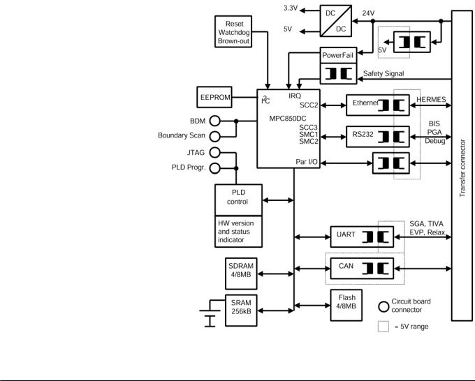
3.1DIANA PCB
3.1.1 |
Purpose |
The DIANA PCB handles the communication of all system processors with |
|
|
the HERMES via an Ethernet link. By way of the Transfer PCB the relevant |
|
|
signals of various modules and the 24 V supply are routed to the DIANA |
|
|
PCB. The internal 3.3 and 5 V operating voltages are generated on the |
|
|
DIANA PCB by means of DC/DC-converters. |
3.1.2 |
Function |
The central module of the DIANA PCB is the processor MPC 850 (Figure 3). |
Released Printed on 04.05.06 F5133001 PCB Box.fm |
reserved. Copyright reserved. |
Version 1.0_ |
All rights |
Figure 3 Block diagram of the DIANA PCB
5133.001 |
15 |

Function Description |
Zeus |
|
|
The operating program is located in a 4 or 8 MB Flash-ROM which is loaded into a 4 or 8 MB SDRAM as appropriate during start-up. Key software components can be stored in a 256 kB SRAM which is battery-buffered to protect against failure of the operating voltage. Key parameters can additionally be saved to an EEPROM via an I2C-port.
In addition to the memory modules, a CAN-controller and a four-way-UART are also connected to the system bus. The modules are selected by way of a PLD. The CAN-controller handles most of the communication with the other processors in the overall system with the aid of the installed SABUS-protocol. The four-way UART handles the communication with the ILCA module and with any subsequent add-ons. An Ethernet controller handles the communication with the HERMES system. The IRIA module and a serial port for Service are connected via an electrical isolator directly to the processor. The power supply unit generates a Power Fail signal indicating failure of its primary voltage (240 V mains voltage). The 24 V is also monitored in order to utilize time reserves prior to total failure of the supply voltage for regulation shutdown of the processor. An additional integrated module monitors the 3.3 V supply (Brown-Out monitor).
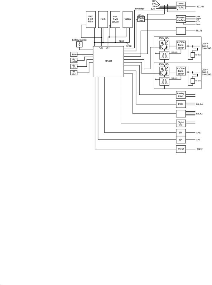
3.2VERONA PCB
3.2.1 |
Purpose |
The VERONA PCB is required in the ZEUS to control the ventilator and to |
|
|
interface to the CAN bus. For this, a microcontroller system based on the |
|
|
PPC555 is used. |
3.2.2 |
Function |
The circuit is operated with a 24 V supply (Figure 4). |
reserved. Copyright reserved. |
Released Printed on 04.05.06 F5133001 PCB Box.fm |
All rights |
Version 1.0 |
16 |
5133.001 |
Zeus |
Function Description |
|
|
Released Printed on 04.05.06 F5133001 PCB Box.fm |
reserved. Copyright reserved. |
Version 1.0_ |
All rights |
Figure 4 Block diagram of the VERONA PCB
The voltage supply is fed in via an EMC-filter and monitored by the controller. The controller PPC555 has an internal RAM which can be optionally batterybuffered. The following operating voltages are generated on the PCB:
–3.3 V for microcontroller
–5 V for temperature sensors
–5 V for digital modules
–12 V for pressure sensors
The processor system has two serial ports (max 115 kbaud). Two CAN-inter- faces actively support the Full CAN V2.0A and V2.0B-protocol at up to 1Mb/s. The CAN-buses are each isolated from the rest of the system and from each other by an isolating voltage of at least 500 V AC. Optocouplers are used to isolate the signals. To activate the blower motor the board has a dedicated interface. The power electronics for the blower are located on the Vent Power PCB. For speed evaluation the three TTL-signals Hall-A, Hall-B and Hall-C
5133.001 |
17 |
Function Description |
Zeus |
|
|
are delivered by the motor electronics. The motor temperature is evaluated, as are the other temperature sensors. 6 LEDs are provided for output of status signals. The following LEDs are interesting for service work:
–12 V supply voltage = LED V405
–5 V supply voltage = LED V402
If only LED V302 of the 4 LEDs between the SUB-D connectors is lit the hardware is in test mode.
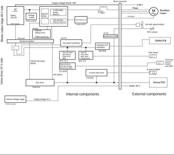
3.3Vent Power PCB
3.3.1 |
Purpose |
The Vent Power PCB contains the power electronics to activate the blower |
|
|
and the external valves. It provides the link between the valve control and the |
|
|
pneumatic system. |
3.3.2 |
Function |
The respective power stages can be disabled by an external signal (Figure |
|
|
5). |
Figure 5 Vent Power PCB block diagram
This signal is generated by an independent monitoring computer. In addition to the power stages, the sender information from the TurboVent and the status signals of the various output stages are processed and passed on for evaluation to the TurboVent control computer. The supply voltage of the TurboVent is 48 V DC and that of the valves is normally 24 V. Because of the different supply voltages and the substantial peak currents in the TurboVent activation circuit these blocks are electrically isolated by optocoupler.
18 |
5133.001 |
reserved. Copyright reserved. |
Released Printed on 04.05.06 F5133001 PCB Box.fm |
All rights |
Version 1.0 |

Released Printed on 04.05.06 F5133001 PCB Box.fm |
reserved. Copyright reserved. |
Version 1.0_ |
All rights |
Zeus |
Function Description |
|
|
The supply voltage for the TurboVent is externally stabilised in the power supply unit to 48 V and has a current limit of 3 A. An external 68000 uF capacitor is included to deal with the high peak currents of the motor.
The function of the blower power stage is to provide phase-adjusted activation of the motor coil with the aid of the Hall sensors built into the motor and to control the speed of the motor. The Hall signals are formatted by an inverter and passed to the Hall decoder. This module decodes the Hall signals of the motor and codes the activation signals of the MOSFET driver from them. The power MOSFETs are activated by a MOSFET driver. The output stage comprises 3 half-bridges each with two identical n-channel MOSFETs. At a TurboVent electronics supply voltage below 38 V a protective circuit disables the MOSFET activation. As the motor is run in a highly dynamic mode at high speeds, the power stage is rated for a peak power output of approximately 480 W. The mean load in operation is approximately 100 W.
The fan delivers one pulse per fan wheel revolution. This pulse is filtered by an RC element and routed to a retriggerable monoflop. If the pulses are not received, the monoflop drops out and disables the power electronics for the TurboVent. This ensures that the TurboVent is only activated when the fan is running. This prevents harmful overheating or excessive oxygen concentration build-up at the TurboVent motor.
The Vent Power PCB also contains the activation electronics for the valves in the breathing system and their interface to the TurboVent control computer. Additionally, the Ventilator-OFF signal is evaluated by the DIANA PCB to cut the power to the driver stages.
The A-cone valve is a single-turn bipolar valve. The turn must be activated in bipolar mode by a voltage pulse. This valve driver is independent of the Ven- tilator-OFF signal.
The power electronics for the flow valves are located directly at the pneumatic interface underneath the valves, and not on this PCB. However, the valves are shut off by the Ventilator-OFF signal by way of a HIGH-side FET switch on this module. The switch cuts the supply voltage to the flow valves.
The valves, seal, fresh gas, switch-over and BAG are controlled by a low-side MOSFET switch. This module has a monitoring output which is routed to the TurboVent control computer. The monitoring covers short-circuit and open load.
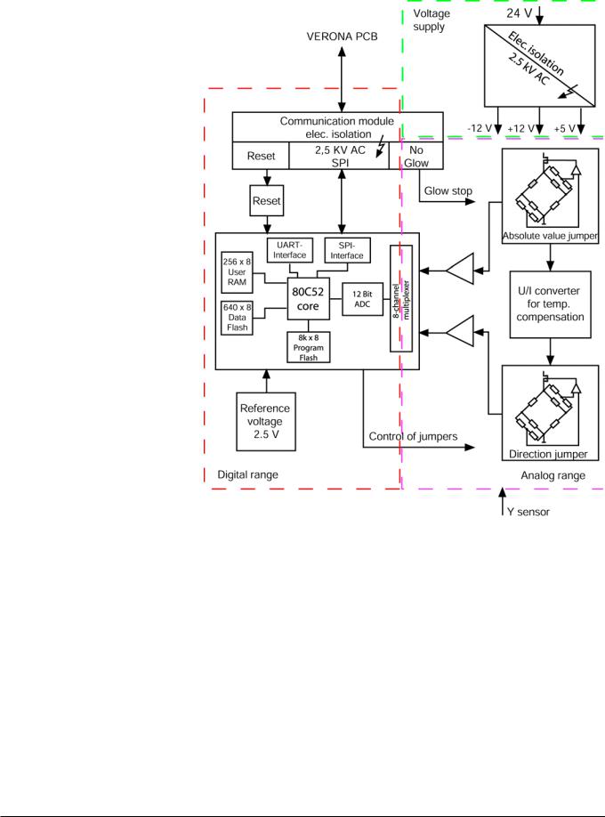
3.4External Flow PCB
3.4.1 Purpose |
The “Alveon” flow sensor is designed for adult patient-local directional flow |
|
measurement and is built into the patient Y-piece. The External Flow PCB |
|
digitises the sensor signals and supplies the data via SPI. |
3.4.2External Flow PCB func- The External Flow PCB circuitry is divided into 3 areas (Figure 6):
tion |
– Supply voltage with electrical isolation from the overall system |
|
|
|
– Analog measurement processing |
|
– Digital measurement processing with data interface and electrical isola- |
|
tion from VERONA PCB via SPI |
5133.001 |
19 |
Function Description |
Zeus |
|
|
Figure 6 External Flow PCB block diagram
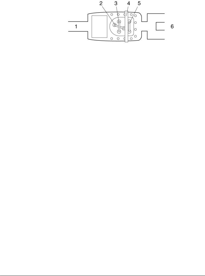
3.4.3Sensor measurement The “Alveon” flow sensor is based on the principle of a filament anemometer
principle |
(Figure 7). In conjunction with the Zeus anaesthetic workstation, the measur- |
|
ing wire (2) is used for compensation of the breathing gas, the measuring |
|
wire (3) for “flow measurement” and the measuring wire (5) with the shading |
|
(4) for detecting the direction of flow. |
reserved. Copyright reserved. |
Released Printed on 04.05.06 F5133001 PCB Box.fm |
All rights |
Version 1.0 |
20 |
5133.001 |
Zeus |
Function Description |
|
|
Figure 7 “Alveon” flow sensor layout
Released Printed on 04.05.06 F5133001 PCB Box.fm |
reserved. Copyright reserved. |
Version 1.0_ |
All rights |
5133.001 |
21 |

22 |
Function |
|
Description |
001.5133
All rights reserved. Copyright reserved.
Zeus
Version 1.0_ Released_Printed on_04.05.06_F5133001_PCB_Box.fm
 Loading...