

Page 1

RETURN TO SERVICE PROCEDURE TABLE OF CONTENTS
DrägerService
RETURN TO CD-ROM TABLE OF CONTENTS
®
Field
Service
Procedure
Part Number: SP00091
Date: 11 July 2001
© 2001 Draeger Medical, Inc.
Rev: H
KIT, TEC 6 DESFLURANE
VAPORIZER INSTALLATION, NAD VARIANT
Page 2

RETURN TO SERVICE PROCEDURE TABLE OF CONTENTS
RETURN TO CD-ROM TABLE OF CONTENTS
Page 3
RETURN TO SERVICE PROCEDURE TABLE OF CONTENTS
RETURN TO CD-ROM TABLE OF CONTENTS
KIT, TEC 6 DESFLURANE
VAPORIZER INSTALLATION, NAD VARIANT
INSTALLATION PROCEDURE
NOTE: The following procedure is performed after all host NARKOMED Anesthesia Systems
have been upgraded, if applicable, in accordance with TSB #103.
NOTE: The desflurane vaporizer shall be installed in the extreme right position (as viewed
from the front) on the machine.
NOTE: If the host machineisaNARKOMED4, its gas analyzer must be configured to include
desflurane. Refer to Service Procedure SP00117 for details.
If the host machine is a NARKOMED 3, its gas analyzer must be configured to include
desflurane. Refer to Service Procedure SP00121 for details.
NOTE: Proceed to Step 5 if you are not
removing an existing vaporizer.
1. Before removing an existing
vaporizer or bypass block from the
machine, perform a low pressure
leak test at the fresh gas outlet to
verify gas circuit integrity.
2. If there is an existing vaporizer in
place, it must be drained and dried
as follows:
CAUTION
The following steps must be
performed in the sequence given.
2.3 Open the APL valve by turning it
fully counter-clockwise.
2.4 Short circuit the inspiratory and
expiratory valves with a 22 mm
hose.
2.5 Ensure that the fresh gas hose is
connected to the 15 mm connector
on the machine.
2.6 Turn the System Power switch to
ON.
2.7 Set all vaporizer handwheels to
their Zero or OFF position.
WARNING
2.1 Activate the waste gas scavenger
system.
2.2 Attach a breathing bag to the bag
mount connector.
Do not inhale anesthetic vapors as
this could result in personal injury.
1
Page 4

RETURN TO SERVICE PROCEDURE TABLE OF CONTENTS
INSTALLATION PROCEDURE (continued)
RETURN TO CD-ROM TABLE OF CONTENTS
2.8 Open the filler and drain plugs, and
drain the vaporizer into a suitable
container. Dispose of the residual
agent in an approved manner.
2.9 Close the filler and drain plugs.
2.10 Turn the vaporizer handwheel to
themaximumconcentrationsetting.
2.11 Set the oxygen flow to 10 l/min. for
at least 20 minutes.
2.12 Turn the vaporizer handwheel to 0
(zero), turn the oxygen flow off and
set the System Power switch to
STANDBY.
3. While holding the vaporizer,
remove the mounting screws and
carefully separate the vaporizer
from the machine.
4. Place the vaporizer in a suitable
container for transport or storage.
5. Remove the desflurane vaporizer
from its packing container and
inspect the vaporizer for damage.
6. Verify that the dial (handwheel) is
set to Standby.
7. Place an O-ring (supplied by the
vaporizer manufacturer) in each
recess of the mounting surface of
the vaporizer.
WARNING
DO NOT use the Dräger O-rings
when installing the desflurane
vaporizer. The Dräger O-rings may
cause occlusion of the gas passages
when used with desflurane.
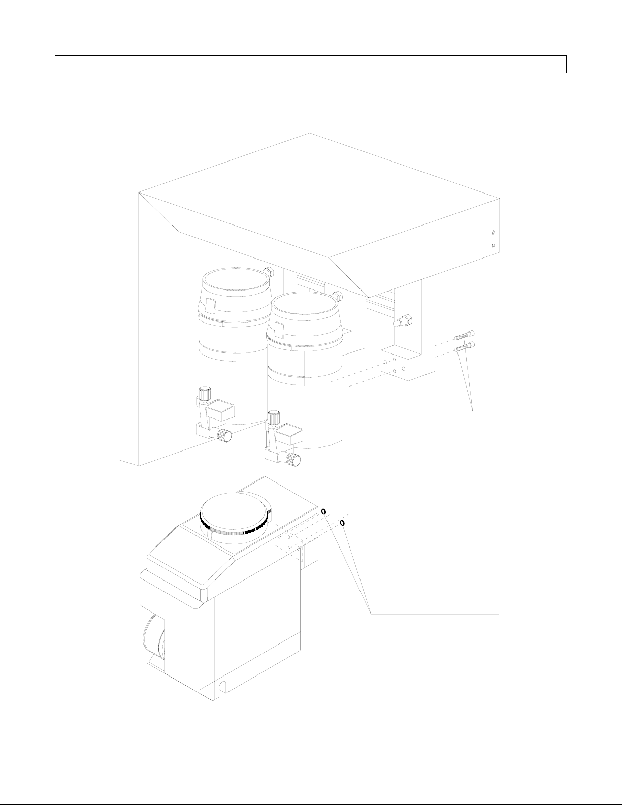
8. Secure the vaporizer to the machine
with two 35 mm long screws
(Ohmeda supplied by the vaporizer
manufacturer). See Figure 1.
WARNING
If the Desflurane vaporizer is later
removed from the machine and a
Dräger vaporizer installed in its
place, DO NOT use the Ohmeda
screws or the Ohmeda O-rings to
mount the Dräger vaporizer. The
longer Ohmeda screws will bottom
out and will not allow a gas tight
seal between the Dräger vaporizer
and the machine.
2
Page 5
RETURN TO SERVICE PROCEDURE TABLE OF CONTENTS
INSTALLATION PROCEDURE (continued)
RETURN TO CD-ROM TABLE OF CONTENTS
SP91001
VAPORIZER
MOUNTING SCREWS
(USE ONLY OHMEDA SCREWS -
SEE TEXT)
O-RINGS
(USE ONLY OHMEDA O-RINGS
SEE TEXT)
Figure 1: DESFLURANE VAPORIZER INSTALLATION
3
Page 6
L
U
RETURN TO SERVICE PROCEDURE TABLE OF CONTENTS
INSTALLATION PROCEDURE (continued)
RETURN TO CD-ROM TABLE OF CONTENTS
9. Test the long pivot arm of the
vaporizer interlock assembly with a
magnet. If the pivot arm is
magnetic, skip to Step 14.
NOTE: Unused pivot arms may be
returned to:
North American Dräger
Technical Service Department
3122 Commerce Drive
Telford, PA 18969
Attn: Desflurane Coordinator
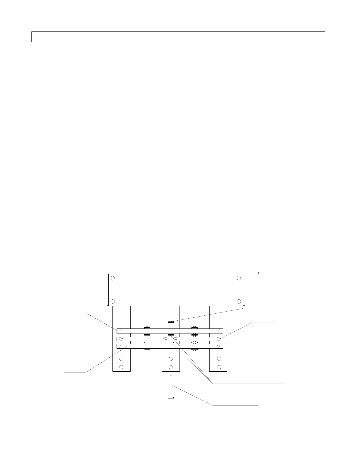
10. Remove the upper retaining clip
securing the center pivot pin to the
vaporizer interlock assembly. See
Figure 2.
11. Slide the pin out from the assembly
(do not misplace the two spacers)
and remove the long pivot arm.
12. Transfer the two locking hex nuts
and the two set screws from the
existing pivot arm to the new pivot
arm included in the Desflurane
Installation Kit.
13. Assemble the new pivot arm onto
the interlock assembly as follows:
Slide the pivot pin up into the
lower support bar, place a spacer on
the pin, place the new pivot arm
onto the pin, slide the pin up
through the pivot arm, place
another spacer on the pin and
continuesliding the pin through the
upper support bar. Secure the pin
to the assembly with the retaining
clip
14. Attachthedesflurane warning label
(included in the Desflurane
Installation Kit) to the right side of
sloping front vapor box panel.
(Choose another location on the
sloping front panel if the right side
is already occupied by another
label.)
VAPORIZER
SP91006
INTERLOCK
MECHANISM
REAR VIEW
RETAINING CLIP
PPER
SUPPORT BAR
LONG PIVOT
ARM
OWER
SUPPORT BAR
SPACERS
CENTER PIVOT PIN
Figure 2: INTERLOCK MECHANISM - LONG PIVOT ARM INSTALLATION
4
Page 7

SP91002
UNDERSIDE VIEW OF DESFLURANE VAPORIZER
AC LINE
CORD
AC LINE CORD
ROUTING
AC LINE CORD
RETAINER PLATE
CABLE
CLAMP
AC LINE CORD
CHANNEL
RETURN TO SERVICE PROCEDURE TABLE OF CONTENTS
INSTALLATION PROCEDURE (continued)
RETURN TO CD-ROM TABLE OF CONTENTS
15. Remove the AC line cord retainer
plate from the bottom of the
vaporizer. Insert the AC line cord
firmly into the socket of the
vaporizer and route the cord
through the channel as indicated in
Figure 3.
Open the retainer loop on the back
of the vaporizer and snap the cord
into the loop.
Reinstall the AC line cord retainer
plate.
CAUTION
DO NOT use the convenience
receptacle on the Narkomed
machine.
16. Plug the vaporizer line cord into an
AC receptacle.
Figure 3: DESFLURANE VAPORIZER AC LINE CORD INSTALLATION
5
Page 8

TEST PROCEDURE
SETSCREW C
VAPORIZER
INTERLOCK
MECHANISM
REAR VIEW
SP91005
SETSCREW B
(RECESSED)
SETSCREW A
(RECESSED)
SETSCREW D
LOCKNUTLOCKNUT
RETURN TO SERVICE PROCEDURE TABLE OF CONTENTS
RETURN TO CD-ROM TABLE OF CONTENTS
1. Perform the "Alarm and Display
Test" and "Preoperative Checkout"
as described in the Datex-Ohmeda
Tec 6 or Tec 6 Plus Operation and
Maintenance Manual supplied with
the vaporizer. NOTE: If this
information is not available contact
the manufacturer.
Vaporizer Exclusion System
Adjustment:
WARNING
Toensure proper operation of the vaporizer
exclusion system with the desflurane
vaporizer and its dial overload mechanism,
it is imperative that each step of the
vaporizer exclusion system adjustment
procedure be followed exactly as written.
2. Turn on the left mounted vaporizer
by depressing the "0" button while
turning the handwheel.
3. Depress the "0" button on the
center mounted vaporizer and
verify that the vaporizer can not be
turned on. Also verify that there is
a minimal amount of "free play" in
the handwheel and the interlock
mechanism. If adjustment is
required, tighten set screw A (see
Figure 4) until the vaporizer locks
without "free play".
Figure 4: VAPORIZER INTERLOCK ADJUSTMENT
6
Page 9

TEST PROCEDURE (continued)
RETURN TO SERVICE PROCEDURE TABLE OF CONTENTS
RETURN TO CD-ROM TABLE OF CONTENTS
NOTE: Do not over-tighten the set
screw. Each vaporizer
handwheel or dial must turn
easily while the other
vaporizers are locked.
4. Turn off the left mounted vaporizer,
and turn on the center mounted
vaporizer. Check the left vaporizer
for "free play" as in Step 3. Turn off
the center vaporizer.
5. Turn on the desflurane vaporizer by
fully depressing the dial release,
then rotating the dial.
6. Loosen the lock nut securing set
screw C or D on the long pivot arm
(see Figure 4), and back out the set
screw several turns.
7. Re-tighten the set screw to just
eliminate play from the left
mounted vaporizer, then back out
the set screw ½ revolution counterclockwise.
9. Turn on the left mounted vaporizer
by depressing its "0" button while
turning the handwheel - just far
enough to engage the vapor
exclusion system.
10. Attempt to turn on the desflurane
vaporizer by applying torque to the
dial while slowly squeezing the dial
release. Verify that the dial release
collapses without allowing the dial
to be turned on. Repeat this check
three more times with the
handwheel of the left mounted
vaporizer at , and full on. See
table below for equivalent
handwheel settings.
Repeat Steps 5 thru 10 if necessary
to obtain correct operation of the
desflurane vaporizer dial.
NOTE: If the unit can not be
successfully adjusted,
contact the NAD Technical
Service Department.
7A. While depressing its "0" button,
verify that the vaporizer can not be
turned on. Secure the lock nut
while holding the set screw to
10A. Loosen the lock nut securing set
screw C or D on the long pivot arm
(see Figure 4), and turn in the set
screw ½ revolution clockwise.
maintain correct adjustment.
11. Turn off the left mounted vaporizer.
8. Turn the desflurane vaporizer dial
to STANDBY.
12. Turn on the desflurane vaporizer by
fully depressing the dial release,
and then rotating the dial.
Vaporizer Just On On On Full On
Halothane <0.2% 0.4% 2% 5%
Enflurane <0.3% 1% 3.5% 7%
Isoflurane <0.2% 0.4% 2% 5%
7
Page 10

TEST PROCEDURE (continued)
RETURN TO SERVICE PROCEDURE TABLE OF CONTENTS
RETURN TO CD-ROM TABLE OF CONTENTS
NOTE: If the interlock assembly is
adjusted so that there is too
much force on the
desflurane vaporizer, an
overload mechanism within
the dial will prevent the
vaporizer from being
activated.
Repeat Steps 2 thru 10 if the note
applies.
13. Turn the desflurane vaporizer dial
to STANDBY.
13A. Repeat Steps 9 and 10 to verify the
integrity of the adjustment.
13B. Turn off the left mounted vaporizer.
14. Turn on the desflurane vaporizer by
fully depressing the dial release,
then rotating the dial.
15. Back out set screw B several turns.
See Figure 4.
16. Re-tighten the set screw to just
eliminate play from the center
mounted vaporizer, then back out
the set screw ½ revolution counterclockwise.
19. Attempt to turn on the desflurane
vaporizer by applying torque to the
dial while slowly squeezing the dial
release. Verify that the dial release
collapses without allowing the dial
to be turned on. Repeat this check
three more times with the
handwheel of the center mounted
vaporizer at , and full on. Refer
to the table for equivalent
handwheel settings.
Repeat Steps 14 thru 19 if
necessary to obtain correct
operation of the desflurane
vaporizer dial.
NOTE: If the unit can not be
successfully adjusted,
contact the NAD Technical
Service Department.
19A. Turn in set screw B ½ revolution
clockwise, and repeat Steps 18 and
19.
20. Turn off the center mounted
vaporizer.
21. Turn on the desflurane vaporizer by
fully depressing the dial release,
and then rotating the dial.
16A. While depressing its "0" button,
verify that the vaporizer can not be
turned on.
17. Turn the desflurane vaporizer to
STANDBY.
18. Turn on the center mounted
vaporizer by depressing its "0"
button while turning the handwheel
- just far enough to engage the
vapor exclusion system.
NOTE: If the interlock assembly is
adjusted so that there is too
much force on the
desflurane vaporizer, an
overload mechanism within
the dial will prevent the
vaporizer from being
activated.
Repeat Steps 13B thru 19 if the
note applies.
8
Page 11

RETURN TO SERVICE PROCEDURE TABLE OF CONTENTS
TEST PROCEDURE (continued)
22. Turn the desflurane vaporizer to
STANDBY.
22A. Repeat Steps 18 and 19 to verify
the integrity of the adjustment.
23. After final adjustment has been
made on the exclusion system,
verify that the agent indicator
lamps (if applicable) operate
correctly for all three vaporizers.
RETURN TO CD-ROM TABLE OF CONTENTS
Leak Test:
1. Connect a pressure gauge and
squeeze bulb to the fresh gas outlet.
Pressurize the system to 50 cm
O. After 30 seconds the pressure
H
2
drop shall not be more than 10 cm
O.
H
2
2. Turn the desflurane vaporizer dial
to 1% and repeat the leak test
given in the previous step. Press
the dial release, adjust the setting
to 18% and repeat the test.
3. Turn off all vaporizers and flow
control valves, and turn the System
Power switch to STANDBY. Ensure
that the Ventilator Power switch is
OFF.
9
Page 12

RETURN TO SERVICE PROCEDURE TABLE OF CONTENTS
TEST PROCEDURE (continued)
Desflurane Vaporizer Concentration
Test:
RETURN TO CD-ROM TABLE OF CONTENTS
1. Verify that the Riken Gas Indicator
bears a current calibration sticker.
2. Zero the Riken Gas Indicator Model
18D as per its operator’s manual.
3. Insert a 15 mm male x 15 mm
female elbow into the fresh gas
outlet.
4. Connect a sampling tee between the
elbow and the fresh gas hose 15
mm connector of the absorber.
5. Connect a ¼ in. teflon hose between
the sampling tee and the inlet of
the Riken Gas Indicator Model 18D.
6. Turn the APL valve knob counterclockwise to its fully open position.
7. Attach a short 22 mm hose between
the inspiratory and expiratory
valves.
8. Attach a breathing bag to the
swivel bag mount connector.
9. Set the oxygen flow rate to 10
l/min. to flush the system of
residual gases.
10. Reduce the oxygen flow rate to 5.0
l/min.
11. Verify that the Riken Gas Indicator
Model 18D indicates 0.0% vol. and
re-zero if needed.
12. Turn the desflurane dial to the 4%
setting.
13. Draw a gas sample into the Riken
Gas Indicator Model 18D and read
the gas volume % per the operator’s
manual. Record the reading on the
desflurane vaporizer concentration
verification form.
14. Verify that the value obtained is
within the sum of tolerances of the
Riken Gas Indicator Model 18D and
the vaporizer. (Refer to the
desflurane vaporizer concentration
verification form for High and Low
limits.) Place a check mark in the
appropriate Pass/Fail box on the
form.
15. Repeat the previous three steps at
desflurane vaporizer dial settings of
6%, 10%, 12%, and 16%.
10
Page 13

TEST PROCEDURE (continued)
RETURN TO SERVICE PROCEDURE TABLE OF CONTENTS
RETURN TO CD-ROM TABLE OF CONTENTS
Narkomed 4 Gas Analyzer Configuration
If the desflurane vaporizer is installed on
a Narkomed 4, the machine’s gas analyzer
must be configured for desflurane as
follows:
1. Turn the System Power switch to
ON.
2. Access the Main Service Screen by
pressing and holding the Selection
Dial, and simultaneously press the
MONITOR and SYSTEM CONFIG
keys.
3. Select the Service Mode and enter
your Technical Service
Representative ID number.
4. Enter the Secondary Service Screen
and touch the DES Agent selection
key to allow desflurane. Touch the
Right vaporizer position key, select
and enter DES. Touch the EXIT
key to return to the Main Service
Screen.
Narkomed 3 Gas Analyzer Configuration
(if applicable)
If the desflurane vaporizer is installed on
a Narkomed 3, the machine’s gas analyzer
must be configured for desflurane as
follows:
1. Turn the System Power switch to
ON while simultaneously pressing
the and keys on the
multispec monitor. The multispec
display window will show .
02
2. Turn the desflurane vaporizer dial
on.
3. Press the AGENT SELECT key
until the letter "D" appears in the
display window.
4. Press the DISPLAY key on the
multispec monitor.
5. Turn off the desflurane vaporizer.
6. Turn the System Power switch to
STANDBY, then back to ON.
5. Press the MONITOR key on the
main key panel to return to normal
viewing.
6. Turn the System Power switch to
STANDBY, then back to ON.
7. Verify that the notation
DES
appears on the agent monitor
display.
8. Turn the System Power switch to
STANDBY.
7. Press the DATA key. Turn on the
desfluranevaporizerand verify that
the "DES" abbreviation appears in
the expiratory and inspiratory
agent locations.
8. Turn off the desflurane vaporizer
and turn the System Power switch
to STANDBY.
11
Page 14

RETURN TO SERVICE PROCEDURE TABLE OF CONTENTS
RETURN TO CD-ROM TABLE OF CONTENTS
PARTS REQUIRED
PART DESCRIPTION: Field Install PART NUMBER
Kit, Desflurane Installation, includes: S010188
Long Pivot Arm 4108043
Installation Procedure for
SP00091
Tec 6 Desflurane Vaporizer
Desflurane Warning Label 4112737-001
TEST EQUIPMENT REQUIRED
DESCRIPTION PART NUMBER
Riken Gas Indicator Model 18D
Bulb & Hose Assembly 4109398
Tee for 5/32 ID Tube 4109292
Tube, Corr. 22 mm x 12 in. lg. 9995112
Digital Pressure Manometer SenSym PDM 200CD or
equivalent
Magnet 4110277 or equivalent
12
Page 15

RETURN TO SERVICE PROCEDURE TABLE OF CONTENTS
RETURN TO CD-ROM TABLE OF CONTENTS
DESFLURANE VAPORIZER CONCENTRATION VERIFICATION
Customer _______________________________ AHA #_____________________________
Address ________________________________ Dealer_____________________________
City __________________________________ State __________ Zip _____________________
PO # _____________ Machine Serial # ______________ Vaporizer Serial # ______________
Machine Model __________________________
Dial
Setting
4% 3.28% 4.72%
6% 4.92% 7.08%
10% 8.20% 11.8%
12% 9.84% 14.16%
16% 13.12% 18.88%
Low Lim.
Tolerance
High Lim.
Tolerance
Pass Fail
Comments____________________________________________________________________
_____________________________________________________________________________
_____________________________________________________________________________
Service Representative: I.D. No.: Date:
S010245-
Page 16

RETURN TO SERVICE PROCEDURE TABLE OF CONTENTS
RETURN TO CD-ROM TABLE OF CONTENTS
Page 17

RETURN TO SERVICE PROCEDURE TABLE OF CONTENTS
RETURN TO CD-ROM TABLE OF CONTENTS
Page 18

RETURN TO SERVICE PROCEDURE TABLE OF CONTENTS
DrägerService
RETURN TO CD-ROM TABLE OF CONTENTS
®
DrägerService is a division of
Draeger Medical, Inc.
3122 Commerce Drive
Telford, PA 18969
Tel: (215) 721-5402
(800) 543-5047
Fax: (215) 721-5784
Web: www.draegermedical.com
Printed in the U.S.A.
 Loading...