

Page 1

KIT,SCAVENGERSHUT-OFF
INSTALLATIONPROCEDURE
RETURN TO SERVICE PROCEDURE TABLE OF CONTENTS
RETURN TO CD-ROM TABLE OF CONTENTS
1. Disconnectallpipelinehosesand
close all cylinder valves.
Depressurizethesystem.
2. TurntheSystemPowerswitchto
STANDBY.
3. Removethebackcoverofthe
flowmeterhousing.
CAUTION: Ifoptionalsuctionsystem
piping is present, use
extreme caution when
drillingsoasnottodamage
theDISSvacuumfittingon
therearframerail.
4. ForNarkomed2B,2Cand4:
carefullyenlargetheexisting7/32
in.dia.holeintherearframerail
(seeFigure1)witha5/16in.dia.
drill.
Carefullyde-burrtheholeand
cleanalldrillingchipsfromthe
machineandthesurroundingarea.
5. ForNarkomed2Aand3:measure
andmarktheholelocationonthe
rearframerailasshowninFig.1.
6. Carefullydrilla5/16in.dia.hole.
Carefullyde-burrtheholeand
cleanalldrillingchipsfromthe
machineandthesurroundingarea.
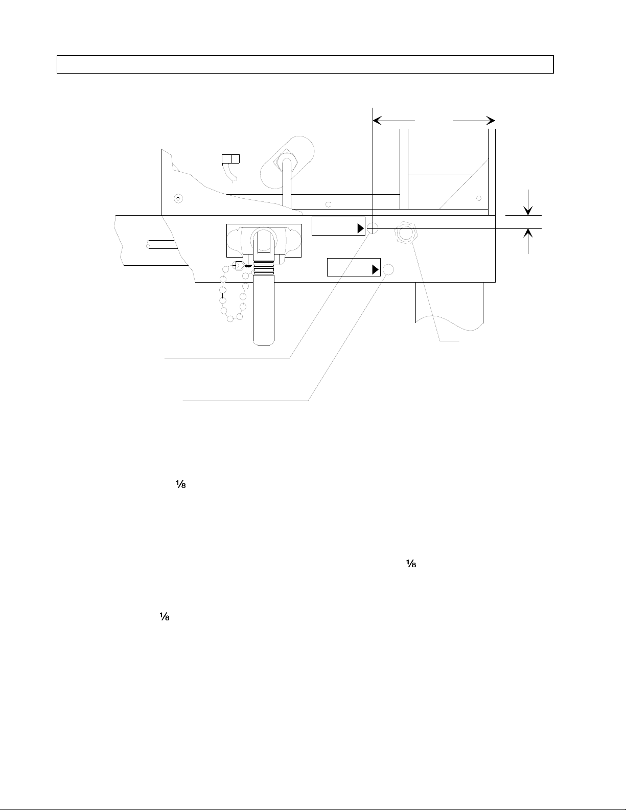
7. InstallthelabelasshowninFigure
1.Thearrowonthelabelshould
pointtothehole.
1
Page 2
RETURN TO SERVICE PROCEDURE TABLE OF CONTENTS
INSTALLATION PROCEDURE (continued)
REAR VIEW OF FRAME RAIL
RETURN TO CD-ROM TABLE OF CONTENTSRETURN TO CD-ROM TABLE OF CONTENTS
SP13601
NARKOMED 2A & 3
LOCATION FOR NEW HOLE
NARKOMED 2B,2C & 4
EXISTING 7/32 IN. DIA.HOLE
3 3/4"
1/2"
OPTIONAL DISS
VACUUM FITTING
(SEE CAUTION IN TEXT)
Figure 1: DRILLING AND LABEL LOCATION
Part of the Scavenger Shut-off Valve Assembly (S/N S010247) has a quick-disconnect bulkhead
fitting at one end of a in. dia. hose assembly, and a nylon tee fitting at the other end of the
assembly. Install this part as outlined in the next three steps:
8. Install the bulkhead fitting & lock
washer in the hole in the frame rail
and secure itwiththe nut provided.
DO NOT overtighten the nut. See
Figure 2.
9. Locate the in. dia. hose connected
to the top of the N
O failsafe
2
assembly, and cut the hose
approximately one inch above the
10. Join the cut ends to the nylon tee
fitting at the end of the scavenger
shut-off in. dia. hose assembly.
Secure each connection with a tie
strap as shown in Figure 2.
11. Install the adhesive-backed cable
clamp on the leg of the machine in
the approximate location shown in
Figure 2.
failsafe.
2
Page 3

RETURN TO SERVICE PROCEDURE TABLE OF CONTENTS
INSTALLATION PROCEDURE (continued)
REAR VIEW OF
FLOWMETER HOUSING
1/8 IN. DIA. HOSE
ASSEMBLY (INCLUDES
RESTRICTOR AND
FITTINGS)
RETURN TO CD-ROM TABLE OF CONTENTSRETURN TO CD-ROM TABLE OF CONTENTS
TIE STRAP (2X)
TEE FITTING
(SUPPLIED WITH
HOSE ASSEMBLY)
N2O FAILSAFE
(REFERENCE)
BULKHEAD FITTING
ASSEMBLY DETAILS
(VIEW ROTATED 90
NUT
LOCKWASHER
QUICK DISCONNECT
BULKHEAD FITTING
º)
Figure 2: TUBING INSTALLATION
CABLE CLAMP
SP13602
3
Page 4

RETURN TO SERVICE PROCEDURE TABLE OF CONTENTS
INSTALLATION PROCEDURE (continued)
RETURN TO CD-ROM TABLE OF CONTENTSRETURN TO CD-ROM TABLE OF CONTENTS
12. Install the shut-off valve assembly
onto the vacuum DISS port of the
scavenger as shown in Figure 3.
13. Connect the pilot line from the
shut-off valve assembly to the quick
disconnect fitting on the rear frame
rail.
Install the pilot line in the cable
clamp on the leg of the machine.
14. Connect a vacuum line to the DISS
fitting on the shut-off valve
assembly, and connect the O
pipeline supply.
15. Cycle the System Power switch and
observe that the ball in the
scavenger flowmeter is at the
bottom of the flowtube when the
machine is in STANDBY, and is
between the white lines on the
flowtube when the machine is ON.
NOTE: The scavenger needle valve may
need slight adjustment to center
the ball between the lines.
16. Test all connections using a leak
detector solution.
2
17. Reinstall the back cover of the
flowmeter housing.
18. Perform a complete PMS procedure
on the machine.
CONNECT TO BULKHEAD FITTING
ON REAR OF FRAME
TO VACUUM
IN
LEFT SIDE VIEW
OF OPEN RESERVOIR
SCAVENGER
SHUT-OFF VALVE ASSEMBLY
(INCLUDES PILOT HOSE AND
VACUUM DISS FITTING)
CLY
SCAVENGER FLOWMETER
SP13603
Figure 3: SHUT-OFF VALVE ASSEMBLY AND PILOT LINE CONNECTION
4
Page 5

NORTH
RETURN TO SERVICE PROCEDURE TABLE OF CONTENTS
RETURN TO CD-ROM TABLE OF CONTENTSRETURN TO CD-ROM TABLE OF CONTENTS
AMERICAN
DRÄGER
Technical Service Department
3122 Commerce Drive
Telford, PA 18969
(215) 721-5402
(800) 543-5047
(215) 723-5935 Fax
Quality Service for Life
®
Part Number: SP00136
Rev: Date: January 6, 1994
© 1994 N.A.D., Inc.
 Loading...