

Page 1
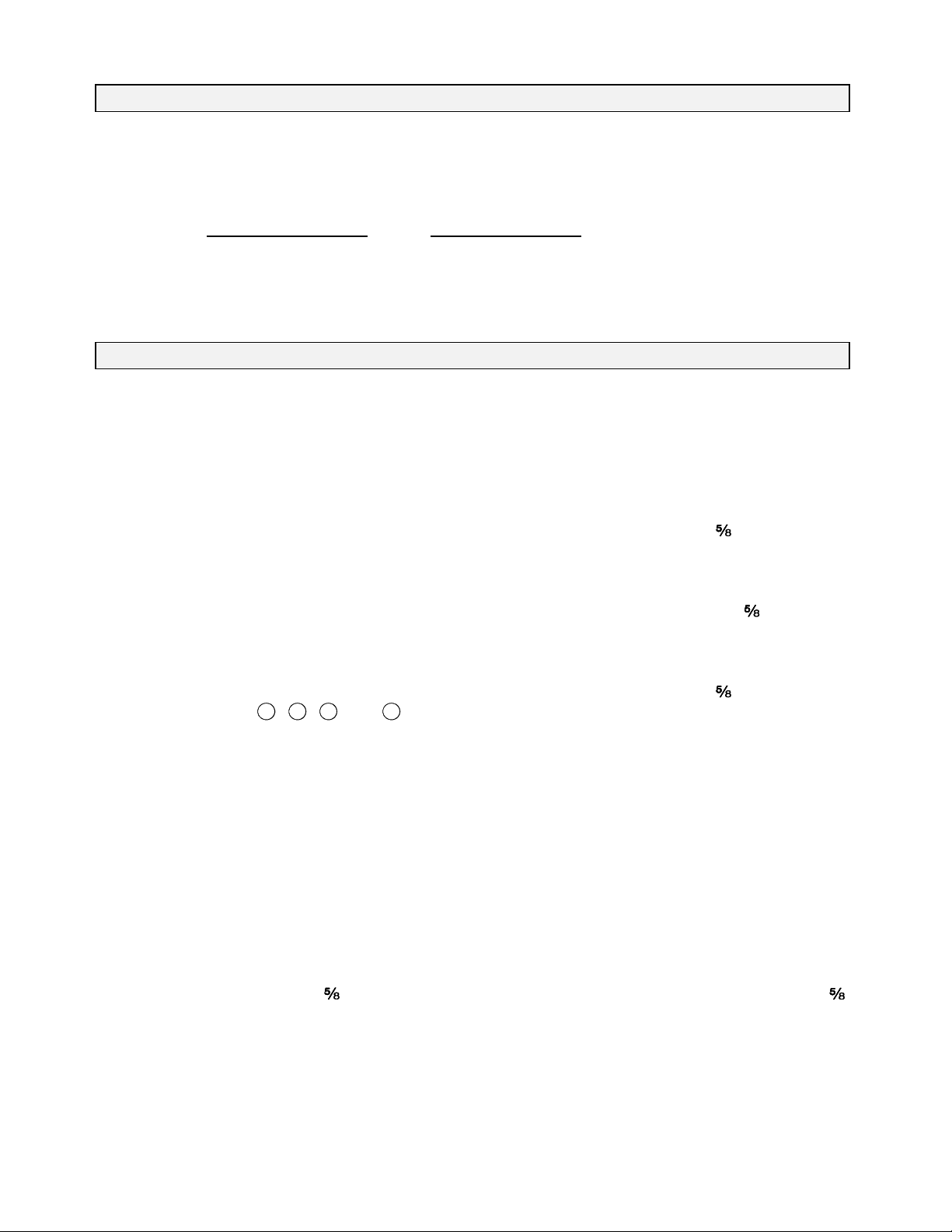
SERVICEPROCEDUREFORINSTALLING:
KITPARTNUMBER KITDESCRIPTION
S4112109-001 Kit,SuctionSystemPiping-DISSBody
S4112109-002 Kit,SuctionSystemPiping-DISSNut
S4112029-003 Kit,SuctionSystemPiping-NISTBody
INSTALLATIONPROCEDURE
RETURN TO SERVICE PROCEDURE TABLE OF CONTENTS
RETURN TO CD-ROM TABLE OF CONTENTS
1. TurntheSystemPowerswitchto
STANDBY,andremoveACpower
fromthemachine.
2. Close all cylinder valves and
disconnectthepipelinesupplies.
3. Removethetabletopfromthe
machine.
4. Removethebackcoverfromthe
flowmeterhousing.
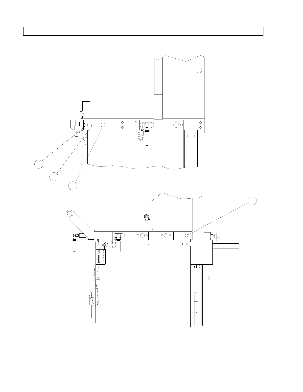
5. Remove the hole plugs from
locationsA,B,CandDonthe
machineasshowninFigure1.
(Somemachinesmaynothavethe
twosmallplugs.)
6. Installthevacuumlabel(P/N
4108447)onthesiderailofthe
machinewithfourdrivescrews
(P/NHW11000).
7. InstallaDISSvacuumfeedthru
fitting(P/N4107958)attheholein
thesiderailofthemachine,and
secureitwithalockwasher(P/N
HW65012)and -18nut(P/N
HW52002)asshowninFigure2.
8. ForKitS4112109-001:
InstalltheDISSvacuumfeedthru
fitting(P/N4107958)intothehole
inthebackrailofthemachine,and
secureitwithalockwasher(P/N
HW65012)and -18nut(P/N
HW52002)asshowninFigure2.
ForKitS4112109-002:
Installthe¼NPTFx -18adapter
(P/N4103915)intotheholeinthe
backrailofthemachineandsecure
theadapterwithalockwasher(P/N
HW65012)and -18nut(P/N
HW52002)asshowninFigure2.
Assemble the DISS nut (P/N
4103122)andDISSvacuumfemale
fitting(P/N4103878),andthread
thefittingintotheadapter.Usea
smallamountofLocquicPrimerT
#747andLoctite#271(red)onthe
threads.
ForKit4112109-003:
InstalltheN.I.S.T.vacuummale
connector(P/N4110389)intothe
holeinthebackrailofthemachine
andsecuretheconnectorwitha
lockwasher(P/NHW65012)and 18nut(P/NHW52002)asshownin
Figure2.
1
Page 2
RIGHT SIDE
VIEW OF MACHINE
SP10201
A
B
C
D
REAR VIEW
OF MACHINE
RETURN TO SERVICE PROCEDURE TABLE OF CONTENTS
INSTALLATION PROCEDURE (continued)
RETURN TO CD-ROM TABLE OF CONTENTSRETURN TO CD-ROM TABLE OF CONTENTS
Figure 1: LOCATION OF HOLE PLUGS
2
Page 3

RETURN TO SERVICE PROCEDURE TABLE OF CONTENTS
INSTALLATION PROCEDURE (continued)
RETURN TO CD-ROM TABLE OF CONTENTSRETURN TO CD-ROM TABLE OF CONTENTS
FEED THRU
VACUUM
DISS FITTING
STRAIGHT
FITTING
VIEW FOR KIT
S4112109-001
(DISS BODY)
ADAPTER
FITTING
STRAIGHT
FITTING
DISS VACUUM
FEMALE FITTING
DISS NUTSTRAIGHT
VIEW FOR KIT
S4112109-002
(DISS NUT)
NIST
VACUUM MALE
CONNECTOR
STRAIGHT
FITTING
FEED THRU
VACUUM
DISS FITTING
COPPER TUBE
TUBING LABEL
NUT (2X)
LOCKWASHER (2X)
Figure 2: SUCTION SYSTEM PIPING INSTALLATION
3
VIEW FOR KIT
S4112109-003
(NIST BODY)
LOCATION OF DISS
VACUUM FITTING AND
LABEL ON RIGHT
SIDE FRAME RAIL
DRIVE SCREWS (4X)
VACUUM LABEL
SP10202
Page 4

SP10203
COPPER
TUBING
COMPRESSION
NUT
TWO-PIECE
FERRULE
1/8in.
RETURN TO SERVICE PROCEDURE TABLE OF CONTENTS
INSTALLATION PROCEDURE (continued)
RETURN TO CD-ROM TABLE OF CONTENTSRETURN TO CD-ROM TABLE OF CONTENTS
9. Thread a ¼ in. tube x MPT
straight fitting into the back of each
feedthru fitting or connector. Use a
small amount of Loctite #271 (red)
on the threads.
10. Install a ¼ in. dia. copper tube (P/N
4103919) between the straight
fittings.
Ensure that the tube is routed
correctly under the inner frame rail
as shown in Figure 2, and ensure
that the Swagelok fittings are
correctly assembled at the tube
ends before tightening the
compression nuts. See Figure 3.
11. Install a VAC label (P/N 4112127)
at each end of the tube.
Figure 3: ASSEMBLY OF SWAGELOK FITTINGS
12. Connect a test fixture with a cm
H
O gauge and squeeze bulb to one
2
end of the vacuum fittings. Occlude
the other fitting and pressurize the
piping to 50 cm H
O. The pressure
2
shall not drop more than 10 cm
H
O per minute.
2
4
13. Reinstall the table top, and
reinstall the flowmeter housing
back cover.
14. Perform a complete PMS on the
machine.
Page 5

NORTH
RETURN TO SERVICE PROCEDURE TABLE OF CONTENTS
RETURN TO CD-ROM TABLE OF CONTENTSRETURN TO CD-ROM TABLE OF CONTENTS
AMERICAN
DRÄGER
Technical Service Department
3122 Commerce Drive
Telford, PA 18969
(215) 721-5402
(800) 543-5047
(215) 723-5935 Fax
Quality Service for Life
®
Part Number: SP00102
Rev: A
Date: April 8, 1994
© 1994 N.A.D., Inc.
 Loading...