

Page 1

RETURN TO THIS MANUAL'S TABLE OF CONTENTS
RETURN TO CD-ROM TABLE OF CONTENTS
Operator’s
Instruction
Manual
Part Number: 4117102-007
Fabius GS Software Version 2.1n
Date: 16 January 2004
© 2004 Draeger Medical, Inc.
Rev: —
Fabius GS
®
Warning: For a full understanding of the performance of this anesthesia machine,
the user should carefully read this manual before operating.
Page 2

RETURN TO THIS MANUAL'S TABLE OF CONTENTS
RETURN TO CD-ROM TABLE OF CONTENTS
Page 3

RETURN TO THIS MANUAL'S TABLE OF CONTENTS
RETURN TO CD-ROM TABLE OF CONTENTS
Contents
Chapter 1. Introduction
Contents . . . . . . . . . . . . . . . . . . . . . . . . . . . . . . . . . . . . . . . . . . . . . . . . . . . . . . . . . . . . . . . . . . . . . . . . . . . 1
Overview . . . . . . . . . . . . . . . . . . . . . . . . . . . . . . . . . . . . . . . . . . . . . . . . . . . . . . . . . . . . . . . . . . . . . . . . . . . 3
Operator’s Responsibility. . . . . . . . . . . . . . . . . . . . . . . . . . . . . . . . . . . . . . . . . . . . . . . . . . . . . . . . . . . . . . . 3
Intended Use . . . . . . . . . . . . . . . . . . . . . . . . . . . . . . . . . . . . . . . . . . . . . . . . . . . . . . . . . . . . . . . . . . . . . . . . 4
Safety Features . . . . . . . . . . . . . . . . . . . . . . . . . . . . . . . . . . . . . . . . . . . . . . . . . . . . . . . . . . . . . . . . . . . . . . 4
Copyright, Trademark, and Limitation of Liability . . . . . . . . . . . . . . . . . . . . . . . . . . . . . . . . . . . . . . . . . . . . 4
Symbol Definition. . . . . . . . . . . . . . . . . . . . . . . . . . . . . . . . . . . . . . . . . . . . . . . . . . . . . . . . . . . . . . . . . . . . . 5
Abbreviations. . . . . . . . . . . . . . . . . . . . . . . . . . . . . . . . . . . . . . . . . . . . . . . . . . . . . . . . . . . . . . . . . . . . . . . . 8
General Warnings and Cautions . . . . . . . . . . . . . . . . . . . . . . . . . . . . . . . . . . . . . . . . . . . . . . . . . . . . . . . . . 9
Chapter 2. Configurations and Components
Contents . . . . . . . . . . . . . . . . . . . . . . . . . . . . . . . . . . . . . . . . . . . . . . . . . . . . . . . . . . . . . . . . . . . . . . . . . . 13
Typical Fabius GS Configuration . . . . . . . . . . . . . . . . . . . . . . . . . . . . . . . . . . . . . . . . . . . . . . . . . . . . . . . . 15
Components . . . . . . . . . . . . . . . . . . . . . . . . . . . . . . . . . . . . . . . . . . . . . . . . . . . . . . . . . . . . . . . . . . . . . . . 15
Chapter 3. Operating Concept
Contents . . . . . . . . . . . . . . . . . . . . . . . . . . . . . . . . . . . . . . . . . . . . . . . . . . . . . . . . . . . . . . . . . . . . . . . . . . 17
Overview . . . . . . . . . . . . . . . . . . . . . . . . . . . . . . . . . . . . . . . . . . . . . . . . . . . . . . . . . . . . . . . . . . . . . . . . . . 19
Standard Function Controls. . . . . . . . . . . . . . . . . . . . . . . . . . . . . . . . . . . . . . . . . . . . . . . . . . . . . . . . . . . . 19
Cross-Functional Controls and Displays . . . . . . . . . . . . . . . . . . . . . . . . . . . . . . . . . . . . . . . . . . . . . . . . . . 20
Monitoring . . . . . . . . . . . . . . . . . . . . . . . . . . . . . . . . . . . . . . . . . . . . . . . . . . . . . . . . . . . . . . . . . . . . . . . . . 22
Ventilation . . . . . . . . . . . . . . . . . . . . . . . . . . . . . . . . . . . . . . . . . . . . . . . . . . . . . . . . . . . . . . . . . . . . . . . . . 26
Fresh Gas Control . . . . . . . . . . . . . . . . . . . . . . . . . . . . . . . . . . . . . . . . . . . . . . . . . . . . . . . . . . . . . . . . . . . 37
Fresh Gas Flow Monitoring Resolutions . . . . . . . . . . . . . . . . . . . . . . . . . . . . . . . . . . . . . . . . . . . . . . . . . . 38
APL Valve . . . . . . . . . . . . . . . . . . . . . . . . . . . . . . . . . . . . . . . . . . . . . . . . . . . . . . . . . . . . . . . . . . . . . . . . . 39
Chapter 4. Preparation
Contents . . . . . . . . . . . . . . . . . . . . . . . . . . . . . . . . . . . . . . . . . . . . . . . . . . . . . . . . . . . . . . . . . . . . . . . . . . 41
Activating the Battery. . . . . . . . . . . . . . . . . . . . . . . . . . . . . . . . . . . . . . . . . . . . . . . . . . . . . . . . . . . . . . . . . 43
Gas Supply . . . . . . . . . . . . . . . . . . . . . . . . . . . . . . . . . . . . . . . . . . . . . . . . . . . . . . . . . . . . . . . . . . . . . . . . 43
Medical Gas Pipeline Supply of O2, N2O, and AIR. . . . . . . . . . . . . . . . . . . . . . . . . . . . . . . . . . . . . . . . . . 43
Cylinders with Pin-index Mounting . . . . . . . . . . . . . . . . . . . . . . . . . . . . . . . . . . . . . . . . . . . . . . . . . . . . . . 44
Electrical Supply . . . . . . . . . . . . . . . . . . . . . . . . . . . . . . . . . . . . . . . . . . . . . . . . . . . . . . . . . . . . . . . . . . . . 45
Attaching Manual (Ambu) Ventilation Bag. . . . . . . . . . . . . . . . . . . . . . . . . . . . . . . . . . . . . . . . . . . . . . . . . 45
Preparing the Ventilator. . . . . . . . . . . . . . . . . . . . . . . . . . . . . . . . . . . . . . . . . . . . . . . . . . . . . . . . . . . . . . . 46
Ventilator Safety Features . . . . . . . . . . . . . . . . . . . . . . . . . . . . . . . . . . . . . . . . . . . . . . . . . . . . . . . . . . . . . 46
Attaching the CO
Attaching the Inspiratory Valve . . . . . . . . . . . . . . . . . . . . . . . . . . . . . . . . . . . . . . . . . . . . . . . . . . . . . . . . . 47
Attaching the Expiratory Valve . . . . . . . . . . . . . . . . . . . . . . . . . . . . . . . . . . . . . . . . . . . . . . . . . . . . . . . . . 47
Attaching the Adjustable Pressure Limiting (APL) Valve. . . . . . . . . . . . . . . . . . . . . . . . . . . . . . . . . . . . . . 47
Inserting the Flow Sensor . . . . . . . . . . . . . . . . . . . . . . . . . . . . . . . . . . . . . . . . . . . . . . . . . . . . . . . . . . . . . 48
Attaching the Waste Gas Outlet Port. . . . . . . . . . . . . . . . . . . . . . . . . . . . . . . . . . . . . . . . . . . . . . . . . . . . . 48
Connecting the Compact Breathing System . . . . . . . . . . . . . . . . . . . . . . . . . . . . . . . . . . . . . . . . . . . . . . . 48
Connecting the Breathing Hoses. . . . . . . . . . . . . . . . . . . . . . . . . . . . . . . . . . . . . . . . . . . . . . . . . . . . . . . . 49
Inserting A New O
Connecting the O2 Sensor . . . . . . . . . . . . . . . . . . . . . . . . . . . . . . . . . . . . . . . . . . . . . . . . . . . . . . . . . . . . 50
Connecting the Pressure Sensor. . . . . . . . . . . . . . . . . . . . . . . . . . . . . . . . . . . . . . . . . . . . . . . . . . . . . . . . 50
Connecting the Breathing Pressure Gauge. . . . . . . . . . . . . . . . . . . . . . . . . . . . . . . . . . . . . . . . . . . . . . . . 51
Connecting the APL Bypass and Peep/PMAX Hoses . . . . . . . . . . . . . . . . . . . . . . . . . . . . . . . . . . . . . . . . 51
2 Absorber onto the Compact Breathing System . . . . . . . . . . . . . . . . . . . . . . . . . . . . . . 46
2 Sensor Capsule . . . . . . . . . . . . . . . . . . . . . . . . . . . . . . . . . . . . . . . . . . . . . . . . . . . . . 49
i
Page 4

RETURN TO THIS MANUAL'S TABLE OF CONTENTS
RETURN TO CD-ROM TABLE OF CONTENTS
Contents
Connecting the Flow Sensor . . . . . . . . . . . . . . . . . . . . . . . . . . . . . . . . . . . . . . . . . . . . . . . . . . . . . . . . . . . 52
Installing Anesthetic Gas Scavenging Hose to the Compact Breathing System . . . . . . . . . . . . . . . . . . . . 52
Scavenger System for Fabius GS . . . . . . . . . . . . . . . . . . . . . . . . . . . . . . . . . . . . . . . . . . . . . . . . . . . . . . . 53
Additional Equipment. . . . . . . . . . . . . . . . . . . . . . . . . . . . . . . . . . . . . . . . . . . . . . . . . . . . . . . . . . . . . . . . . 53
Daily and Preuse Checkout Form . . . . . . . . . . . . . . . . . . . . . . . . . . . . . . . . . . . . . . . . . . . . . . . . . . . . . . . 53
Chapter 5. Operation and Shut-down
Contents . . . . . . . . . . . . . . . . . . . . . . . . . . . . . . . . . . . . . . . . . . . . . . . . . . . . . . . . . . . . . . . . . . . . . . . . . . 55
Operation. . . . . . . . . . . . . . . . . . . . . . . . . . . . . . . . . . . . . . . . . . . . . . . . . . . . . . . . . . . . . . . . . . . . . . . . . . 57
Preparation for Transport or Storage. . . . . . . . . . . . . . . . . . . . . . . . . . . . . . . . . . . . . . . . . . . . . . . . . . . . . 64
Chapter 6. Monitoring
Contents . . . . . . . . . . . . . . . . . . . . . . . . . . . . . . . . . . . . . . . . . . . . . . . . . . . . . . . . . . . . . . . . . . . . . . . . . . 67
Overview . . . . . . . . . . . . . . . . . . . . . . . . . . . . . . . . . . . . . . . . . . . . . . . . . . . . . . . . . . . . . . . . . . . . . . . . . . 69
Alarms . . . . . . . . . . . . . . . . . . . . . . . . . . . . . . . . . . . . . . . . . . . . . . . . . . . . . . . . . . . . . . . . . . . . . . . . . . . . 69
Oxygen Monitoring . . . . . . . . . . . . . . . . . . . . . . . . . . . . . . . . . . . . . . . . . . . . . . . . . . . . . . . . . . . . . . . . . . 70
Respiratory Volume Monitoring . . . . . . . . . . . . . . . . . . . . . . . . . . . . . . . . . . . . . . . . . . . . . . . . . . . . . . . . . 76
Breathing Pressure Monitoring . . . . . . . . . . . . . . . . . . . . . . . . . . . . . . . . . . . . . . . . . . . . . . . . . . . . . . . . . 82
Chapter 7. Setup Window (Used During Operation)
Contents . . . . . . . . . . . . . . . . . . . . . . . . . . . . . . . . . . . . . . . . . . . . . . . . . . . . . . . . . . . . . . . . . . . . . . . . . . 87
Overview . . . . . . . . . . . . . . . . . . . . . . . . . . . . . . . . . . . . . . . . . . . . . . . . . . . . . . . . . . . . . . . . . . . . . . . . . . 89
Setup Window Access. . . . . . . . . . . . . . . . . . . . . . . . . . . . . . . . . . . . . . . . . . . . . . . . . . . . . . . . . . . . . . . . 89
Volume Alarms On/Off. . . . . . . . . . . . . . . . . . . . . . . . . . . . . . . . . . . . . . . . . . . . . . . . . . . . . . . . . . . . . . . . 90
Auto Set. . . . . . . . . . . . . . . . . . . . . . . . . . . . . . . . . . . . . . . . . . . . . . . . . . . . . . . . . . . . . . . . . . . . . . . . . . . 90
Calibrate O2 Sensor . . . . . . . . . . . . . . . . . . . . . . . . . . . . . . . . . . . . . . . . . . . . . . . . . . . . . . . . . . . . . . . . . 90
Activate Desflurane Compensation . . . . . . . . . . . . . . . . . . . . . . . . . . . . . . . . . . . . . . . . . . . . . . . . . . . . . . 91
Access Alarm Log . . . . . . . . . . . . . . . . . . . . . . . . . . . . . . . . . . . . . . . . . . . . . . . . . . . . . . . . . . . . . . . . . . . 92
Access Alarm Volume . . . . . . . . . . . . . . . . . . . . . . . . . . . . . . . . . . . . . . . . . . . . . . . . . . . . . . . . . . . . . . . . 92
Window Deactivation . . . . . . . . . . . . . . . . . . . . . . . . . . . . . . . . . . . . . . . . . . . . . . . . . . . . . . . . . . . . . . . . . 92
Chapter 8. Standby Mode Functions
Contents . . . . . . . . . . . . . . . . . . . . . . . . . . . . . . . . . . . . . . . . . . . . . . . . . . . . . . . . . . . . . . . . . . . . . . . . . . 93
Overview . . . . . . . . . . . . . . . . . . . . . . . . . . . . . . . . . . . . . . . . . . . . . . . . . . . . . . . . . . . . . . . . . . . . . . . . . . 95
Standby Screen . . . . . . . . . . . . . . . . . . . . . . . . . . . . . . . . . . . . . . . . . . . . . . . . . . . . . . . . . . . . . . . . . . . . . 95
Standby Setup Screen. . . . . . . . . . . . . . . . . . . . . . . . . . . . . . . . . . . . . . . . . . . . . . . . . . . . . . . . . . . . . . . . 99
Chapter 9. Routine Maintenance and Cleaning
Contents . . . . . . . . . . . . . . . . . . . . . . . . . . . . . . . . . . . . . . . . . . . . . . . . . . . . . . . . . . . . . . . . . . . . . . . . . 109
Routine Maintenance. . . . . . . . . . . . . . . . . . . . . . . . . . . . . . . . . . . . . . . . . . . . . . . . . . . . . . . . . . . . . . . . 111
Disassembling . . . . . . . . . . . . . . . . . . . . . . . . . . . . . . . . . . . . . . . . . . . . . . . . . . . . . . . . . . . . . . . . . . . . . 111
Disinfecting/Cleaning/Autoclaving . . . . . . . . . . . . . . . . . . . . . . . . . . . . . . . . . . . . . . . . . . . . . . . . . . . . . . 113
Maintenance Intervals . . . . . . . . . . . . . . . . . . . . . . . . . . . . . . . . . . . . . . . . . . . . . . . . . . . . . . . . . . . . . . . 115
Checking Readiness for Operation . . . . . . . . . . . . . . . . . . . . . . . . . . . . . . . . . . . . . . . . . . . . . . . . . . . . . 115
Chapter 10. Troubleshooting
Contents . . . . . . . . . . . . . . . . . . . . . . . . . . . . . . . . . . . . . . . . . . . . . . . . . . . . . . . . . . . . . . . . . . . . . . . . . 117
ii
Page 5

RETURN TO THIS MANUAL'S TABLE OF CONTENTS
RETURN TO CD-ROM TABLE OF CONTENTS
Contents
Chapter 11. Components
Contents . . . . . . . . . . . . . . . . . . . . . . . . . . . . . . . . . . . . . . . . . . . . . . . . . . . . . . . . . . . . . . . . . . . . . . . . . 123
Front View . . . . . . . . . . . . . . . . . . . . . . . . . . . . . . . . . . . . . . . . . . . . . . . . . . . . . . . . . . . . . . . . . . . . . . . . 125
Compact Breathing System (Top View) . . . . . . . . . . . . . . . . . . . . . . . . . . . . . . . . . . . . . . . . . . . . . . . . . 126
Rear View (3-Gas Supply Connections) . . . . . . . . . . . . . . . . . . . . . . . . . . . . . . . . . . . . . . . . . . . . . . . . . 127
Chapter 12. Technical Data
Contents . . . . . . . . . . . . . . . . . . . . . . . . . . . . . . . . . . . . . . . . . . . . . . . . . . . . . . . . . . . . . . . . . . . . . . . . . 129
Technical Data. . . . . . . . . . . . . . . . . . . . . . . . . . . . . . . . . . . . . . . . . . . . . . . . . . . . . . . . . . . . . . . . . . . . . 131
Diagrams . . . . . . . . . . . . . . . . . . . . . . . . . . . . . . . . . . . . . . . . . . . . . . . . . . . . . . . . . . . . . . . . . . . . . . . . . 138
Appendix. Daily and Preuse Checkout Form
iii
Page 6

RETURN TO THIS MANUAL'S TABLE OF CONTENTS
RETURN TO CD-ROM TABLE OF CONTENTS
Page 7

RETURN TO THIS MANUAL'S TABLE OF CONTENTS
RETURN TO CD-ROM TABLE OF CONTENTS
Chapter 1 - Introduction Contents
Introduction
Contents
Overview ................................................................................................................... 3
Recommendations .................................................................................................. 3
Not for Use in Areas of Explosion Hazard .............................................................. 3
Safe Connection with Other Electrical Equipment .................................................. 3
Operator’s Responsibility .......................................................................................... 3
Intended Use ............................................................................................................. 4
Safety Features ......................................................................................................... 4
Copyright, Trademark, and Limitation of Liability ...................................................... 4
Rev: —
Copyright ................................................................................................................ 4
Trademark Notices ................................................................................................. 4
Limitation of Liability ............................................................................................... 4
Symbol Definition ...................................................................................................... 5
Abbreviations ............................................................................................................. 8
General Warnings and Cautions ............................................................................... 9
Part Number: 4117102-007
Fabius GS Operator’s Manual 1
Page 8

RETURN TO THIS MANUAL'S TABLE OF CONTENTS
RETURN TO CD-ROM TABLE OF CONTENTS
Page 9

RETURN TO THIS MANUAL'S TABLE OF CONTENTS
RETURN TO CD-ROM TABLE OF CONTENTS
Overview Chapter 1 - Introduction
Overview
Caution: For your safety and that of your patients,
strictly follow this instruction manual.
Any use of the Fabius GS
and strict observation of these instructions. The unit is
only to be used for purposes specified here.
Recommendations
Because of the sophisticated nature of Draeger
Medical anesthesia equipment and its critical
importance in the operating room setting, it is highly
recommended that only appropriately trained and
experienced professionals, using authentic Draeger
Medical spare parts, be permitted to service and
maintain this equipment. Please contact DrägerService
at (800) 543-5047 or (215) 721-5402 for service of this
equipment.
Draeger Medical also recommends that its anesthesia
equipment be serviced at six-month intervals. Periodic
Manufacturer's Certification Agreements are available
for equipment manufactured by Draeger Medical. For
further information concerning these agreements,
contact DrägerService at (800) 543-5047 or (215) 721-
5402.
®
requires full understanding
are known to the trained operator. Instructions,
warnings, and caution statements are limited,
therefore, to the specifics of the Draeger Medical, Inc.
design. This publication excludes references to
hazards which are obvious to a medical professional,
to the consequences of product misuse, and to
potentially adverse effects in patients with abnormal
conditions. Product modification or misuse can be
dangerous. Draeger Medical, Inc. disclaims all liability
for the consequences of product alterations or
modifications, as well as for the consequences which
might result from the combination of Draeger Medical,
Inc. products with products supplied by other
manufacturers if such a combination is not endorsed
by Draeger Medical, Inc.
The operator of the anesthesia system must recognize
that the means of monitoring and discovering
hazardous conditions are specific to the composition of
the system and the various components of the system.
It is the operator, and not the various manufacturers or
suppliers of components, who has control over the final
composition and arrangement of the anesthesia
system used in the operating room. Therefore, the
responsibility for choosing the appropriate safety
monitoring devices rests with the operator and user of
the equipment.
Rev: —
Part Number: 4117102-007
Not for Use in Areas of Explosion Hazard
The Fabius GS is neither approved nor certified for use
in areas where combustible or explosive gas mixtures
are likely to occur. To avoid explosion hazards,
flammable anaesthetic agents such as ether and
cyclopropane or other flammable substances must not
be used in this machine. Only anaesthetic agents that
comply with the requirements on non-flammable
anaesthetic agents in the IEC Standard, Particular
requirements for the safety of anaesthetic machine,
are suitable for use in this machine.
Safe Connection with Other Electrical
Equipment
Electrical connections to equipment which are not
listed in these Instructions for Use should only be
made following consultations with the respective
manufacturers or an expert and shall be in compliance
with national medical device regulations.
Operator’s Responsibility
The equipment design, the accompanying literature,
and the labeling on the equipment take into
consideration that the purchase and use of the
equipment are restricted to trained professionals, and
that certain inherent characteristics of the equipment
The Fabius GS is equipped to monitor breathing circuit
pressure, exhaled volume and inspired oxygen, and to
sound an alarm when any of these parameters violates
a preset limit. The Fabius GS should not be used if any
of these monitors are not functioning properly. Draeger
Medical, Inc. also recommends that the Fabius GS
only be used to deliver anesthesia and/or mechanical
ventilation in accordance with the guidelines for patient
monitoring published by the American Society of
Anesthesiologists. In addition to volume, pressure, and
oxygen monitoring, these guidelines require the use of
a capnometer to monitor inspired and expired carbon
dioxide as well as other patient monitors including
continuous electrocardiography, pulse oximetry, and
arterial blood pressure monitoring. Anesthetic agent
monitoring and temperature monitoring are also
strongly recommended. The responsibility for the
selection of the best level of patient monitoring belongs
solely to the equipment operator. To this extent, the
manufacturer, Draeger Medical, Inc., disclaims
responsibility for the adequacy of the monitoring
package selected for use with the anesthesia system.
However, Draeger Medical, Inc. is available for
consultation to discuss monitoring options for different
applications.
Fabius GS Operator’s Manual 3
Page 10

RETURN TO THIS MANUAL'S TABLE OF CONTENTS
RETURN TO CD-ROM TABLE OF CONTENTS
Chapter 1 - Introduction Intended Use
Restriction
Caution: Federal law and regulations in the United
States restrict this device to sale by, or on
the order of, a physician.
Intended Use
Fabius GS is an inhalation anesthesia machine for
use in operating, induction and recovery rooms.
It may be used with O
medical gas pipeline system or by externally mounted
gas cylinders.
Fabius GS is equipped with a compact breathing
system, providing fresh gas decoupling, PEEP, and
pressure limitation.
The following ventilation options are available:
• Volume Controlled Ventilation
• Pressure Controlled Ventilation (Optional)
• Pressure Support (Optional)
• Manual Ventilation
• Spontaneous Breathing
Fabius GS is equipped with an electrically driven and
electronically controlled ventilator and monitors for
airway pressure (P), volume (V), and inspiratory
oxygen concentration (FiO
As per EN740 (Anesthetic Workstations and their
Modules- Particular Requirements), additional
monitoring of the concentrations of CO
agent is required when the machine is in use.
Do not use readily flammable anesthetic agents
such as ether, cyclopropane, etc.
2, N2O, and AIR supplied by a
2).
2 and anesthetic
Safety Features
• Monitoring of P, V, FiO2
•O2 SUPPLY LOW alarm
• Integrated S-ORC = Sensitive Oxygen Ratio
Controller (control device to ensure minimum
O
2 concentration of 23 Vol.%).
Per EN740, burns may occur if antistatic or electrically
conductive ventilation tubes are used in combination
with high-frequency electrical surgery equipment.
Therefore, per EN740, these types of breathing tubes
are not recommended.
Caution: Do not use Fabius GS in the environment
of NMR tomography equipment.
Malfunctions may result, thereby
endangering the patient.
Caution: Do not use mobile phones within a distance
of 10 meters from the machine. Mobile
phones can cause malfunctions in electrical
medical equipment, thereby endangering
the patient and the operator.
Copyright, Trademark, and
Limitation of Liability
Copyright
Copyright 2004 by Draeger Medical, Inc. All rights
reserved. No part of this publication may be
reproduced, transmitted, transcribed, or stored in a
retrieval system in any form or by any means,
electronic or mechanical, including photocopying and
recording, without written permission of Draeger
Medical, Inc. The exceptions to this are
“Recommendations for Typical Cleaning and
Disinfection After Use” on page 114 and “Daily and
Preuse Checkout Form” in Appendix A.
Trademark Notices
DrägerService, Fabius GS, and Vitalink are registered
trademarks of Draeger Medical, Inc. Fabius and Vapor
are registered trademarks of Dräger. All other products
or name brands are trademarks of their respective
owners.
Limitation of Liability
Draeger Medical, Inc.'s liability, whether arising from or
related to the manufacture and sale of the products,
their installation, demonstration, sales representation,
use, performance, or otherwise, including any liability
based upon Draeger Medical, Inc.'s product warranty,
is subject to and limited to the exclusive terms of
Draeger Medical, Inc.'s limited warranty, whether
based upon breach of warranty or any other cause of
action whatsoever, regardless of any fault attributable
to Draeger Medical, Inc. and regardless of the form of
action (including, without limitation, breach of warranty,
negligence, strict liability, or otherwise).
Draeger Medical, Inc. shall in no event be liable for any
special, incidental, or consequential damages
(including loss of profits) whether or not foreseeable
and even if Draeger Medical, Inc. has been advised of
the possibility of such loss or damage. Draeger
Medical, Inc. disclaims any liability arising from a
combination of its product with products from another
manufacturer if the combination has not been
endorsed by Draeger Medical, Inc.. Buyer understands
Part Number: 4117102-007
Rev: —
4 Fabius GS Operator’s Manual
Page 11

CUS
RETURN TO THIS MANUAL'S TABLE OF CONTENTS
RETURN TO CD-ROM TABLE OF CONTENTS
Symbol Definition Chapter 1 - Introduction
that the remedies noted in Draeger Medical Inc.'s
limited warranty are its sole and exclusive remedies.
Furthermore, buyer acknowledges that the
consideration for the products, equipment, and parts
sold reflects the allocation of risk and the limitations
of liability referenced herein.
Symbol Definition
The following symbols appear on the labels on the
back of the Fabius GS and are defined below.
Caution: Refer to accompanying documents
before operating equipment.
!
Caution: Risk of electric shock, do not remove
cover. Refer servicing to a
DrägerService representative.
Rev: —
Degree of protection against electric shock: Type B.
Registration Mark
Year Manufactured
The following symbols appear on the shipping
container of the Fabius GS.
This end up.
Handle with care.
Part Number: 4117102-007
Keep dry.
Fabius GS Operator’s Manual 5
Page 12
REV DESCRIPTION DATE BY ECN/DCNAPVD
11-28-00
SAG DLB
00-0922
_
APPROVED
RETURN TO THIS MANUAL'S TABLE OF CONTENTS
RETURN TO CD-ROM TABLE OF CONTENTS
Chapter 1 - Introduction Symbol Definition
Minimum and maximum storage temperatures.
The following symbols are used on other locations of
the Fabius GS to provide quick and easy recognition
of product functions.
Oxygen Concentration Sensor Port
Breathing Pressure Sensor Port
Breathing Volume Sensor Port
60°c
-10°c
Ventilator Port
Pipeline, Gauge, Pipeline Inlet
Breathing Bag
Flowmeter Level Indicator
Indicates Direction
Total Power Applied
Part Number: 4117102-007
Rev: —
6 Fabius GS Operator’s Manual
Page 13
RETURN TO THIS MANUAL'S TABLE OF CONTENTS
RETURN TO CD-ROM TABLE OF CONTENTS
Symbol Definition Chapter 1 - Introduction
Partial Power Applied
Cylinder Gauge, Remote Cylinder Inlet
Do Not Oil
The following symbols are used on the Fabius GS
monitoring user interface.
Table Top Light
Rev: —
Part Number: 4117102-007
Upper and Lower Alarm Limits
Return to Home Screen
Suppress Alarm Tone for Two Minutes
Standby Mode
Available Operating Capacity of UPS
Close Menu, Back to Previous Menu
Upper Alarm Limit
Lower Alarm Limit
Fabius GS Operator’s Manual 7
Page 14
RETURN TO THIS MANUAL'S TABLE OF CONTENTS
RETURN TO CD-ROM TABLE OF CONTENTS
Chapter 1 - Introduction Abbreviations
Mains Applied/Mains Power
Alarm Off
Setup Screen
Abbreviations
Abbreviation Meaning
FLOW Expiratory flow
FiO
2
Freq Ventilation frequency
Freq Min Minimum ventilation frequency setting for Pressure Support Apnea Ventilation
MAN Manual ventilation
MEAN Mean (airway) pressure
N
O Nitrous Oxide
2
O
2
PAW Airway pressure
PEAK Peak (airway) pressure
PEEP Positive end-expiratory pressure
PINSP Pressure setting in Pressure Control mode or the sum of PSUP and PEEP
PLAT Plateau airway pressure
Pmax Maximum (airway) pressure setting
PSUP Pressure Support
SPONT Spontaneous breathing
TI : TE Ratio of inspiratory to expiratory time
Inspiratory O2 concentration
Oxygen
settings in Pressure Support mode
Part Number: 4117102-007
Rev: —
Tip : Ti Ratio of inspiratory pause time to inspiratory time
UPS Uninterruptible power supply
VAC Vacuum (e.g., for secretion aspiration)
VT Tidal volume
8 Fabius GS Operator’s Manual
Page 15

RETURN TO THIS MANUAL'S TABLE OF CONTENTS
RETURN TO CD-ROM TABLE OF CONTENTS
General Warnings and Cautions Chapter 1 - Introduction
Rev: —
Part Number: 4117102-007
General Warnings and Cautions
The following list of warnings and cautions apply to
general operation and maintenance of the
Fabius GS. Warnings and cautions about installing and
operating specific parts appear with those topics.
• A Warning statement gives important information
that, if ignored, could lead directly to personal
injury.
• A Caution statement gives important information
that, if ignored, could lead directly to equipment
damage and indirectly to personal injury.
Warning: Any person involved with the setup,
operation, or maintenance of the
Fabius GS anesthesia system must be
thoroughly familiar with this instruction
manual.
Warning: This anesthesia system will not respond
automatically to certain changes in patient
condition, operator error, or failure of
components. The system is designed to be
operated under the constant surveillance
and control of a qualified operator.
Warning: No third-party components shall be
attached to the anesthesia machine,
ventilator, or breathing system (except for
certain approved exceptions). For more
information, contact your local Authorized
Service Organization or DrägerService at:
DrägerService
Draeger Medical, Inc.
3122 Commerce Drive
Telford, PA 18969
Tel: (215) 721-5402
(800) 543-5047
Fax: (215) 721-5784
Warning: Each institution and user has a duty to
independently assess, based on its, his, or
her unique circumstances, what
components to include in an anesthesia
system. However, Draeger Medical, in the
interest of patient safety, strongly
recommends the use of an oxygen
analyzer, pressure monitor, volume
monitor, and end-tidal CO2 monitor in the
breathing circuit at all times.
Warning: When moving the anesthesia machine,
remove all monitors and equipment from
the top shelf and use only the machine
handles or push/pull bars. The anesthesia
machine should only be moved by people
who are physically capable of handling its
weight. Draeger Medical recommends that
two people move the anesthesia machine
to aid in maneuverability. Exercise special
care so that the machine does not tip
when moving up or down inclines, around
corners, and across thresholds (for
example, in door frames and elevators).
Do not attempt to pull the machine over
any hoses, cords, or other obstacles on
the floor.
Warning: Apply the caster brakes when the
anesthesia machine is in use.
Caution: Although the Fabius GS is designed to
minimize the effects of ambient radiofrequency interference, machine functions
may be adversely affected by the
operation of electrosurgical equipment or
short wave or microwave diathermy
equipment in the vicinity.
Caution: Communications with external equipment
may be temporarily affected by
electromagnetic interference due to the
use of electrosurgical equipment.
Caution: Do not place more than 40 pounds on top
of the Fabius GS monitor housing.
Caution: Never allow the battery to completely
discharge. If the battery does discharge
completely, recharge immediately.
Caution: Front GCX rails have a maximum
accessories weight load of 5 lb./2.3 kg,
extended out at 3 in./7.6 cm from the rail,
at any position on the rail.
Caution: Pressure Support ventilation is triggered
by the patient's spontaneous effort to
breath. Most anesthetic agents will cause
patients to have reduced ventilatory
responses to carbon dioxide and to
hypoxemia. Therefore, patient triggered
modes of ventilation may not produce
adequate ventilation. Additionally, the use
of neuromuscular blocking agents will
interfere with patient triggering.
Fabius GS Operator’s Manual 9
Page 16

Weight
r
Approved
Option
Possible Tip Over
T
RETURN TO THIS MANUAL'S TABLE OF CONTENTS
RETURN TO CD-ROM TABLE OF CONTENTS
Chapter 1 - Introduction General Warnings and Cautions
Fabius GS
Back Left Side
Accessory Option
with Breathing System
Mounted on Left Side
Caution: Possible Tip Ove
Hazard If Mounting Accessories
Exceed Approved Limits.
Mounting Limits
15.0 in.
38.1 cm
10.0 in.
25.4 cm
Mount Arm Length
5.0 in.
12.7 cm
Weight
30 lb. / 13.6 kg
28 lb. / 12.7 kg
26 lb. / 11.8 kg
24 lb. / 10.9 kg
22 lb. / 10.0 kg
20 lb. / 9.1 kg
18 lb. / 8.2 kg
Option
16 lb. / 7.3 kg
14 lb. / 6.4 kg
12 lb. / 5.4 kg
10 lb. / 4.5 kg
Option
Weight
60 lb. / 27.2 kg
55 lb. / 24.9 kg
50 lb. / 22.7 kg
45 lb. / 20.4 kg
40 lb. / 18.1 kg
35 lb. / 15.9 kg
30 lb. / 13.6 kg
25 lb. / 11.3 kg
20 lb. / 9.1 kg
15 lb. / 6.8 kg
10 lb. / 4.5 kg
Approved
Mounting Limits
MAXIMUM WEIGH
PER ARM 30 lb.
COMBINED MULTIPLE
ARM WEIGHTS NOT
TO EXCEED 60 lb. MAX.
5.0 in.
12.7 cm
10.0 in.
25.4 cm
Mount Arm Length
15.0 in.
38.1 cm
Fabius GS
Back Right Side
Accessory Option
with Breathing System
Mounted on Left Side
Caution:
Hazard If Mounting Accessories
Exceed Approved Limits.
Part Number: 4117102-007
Rev: —
10 Fabius GS Operator’s Manual
Page 17

n
10.0 in.
r
A
Caution:
r
T
RETURN TO THIS MANUAL'S TABLE OF CONTENTS
RETURN TO CD-ROM TABLE OF CONTENTS
General Warnings and Cautions Chapter 1 - Introduction
Fabius GS
Back Left Side
Accessory Option
with Breathing System
Mounted on Right Side
Caution: Possible Tip Ove
Hazard If Mounting Accessories
Exceed Approved Limits.
pproved
Mounting Limits
15.0 in.
38.1 cm
25.4 cm
Mount Arm Length
5.0 in.
12.7 cm
Option
Weight
60 lb. / 27.2 kg
55 lb. / 24.9 kg
50 lb. / 22.6 kg
45 lb. / 20.4 kg
40 lb. / 18.1 kg
35 lb. / 15.8 kg
30 lb. / 13.6 kg
Optio
25 lb. / 11.3 kg
Weight
20 lb. / 9 kg
15 lb. / 6.8 kg
10 lb. / 4.5 kg
Rev: —
Part Number: 4117102-007
Option
Weight
30 lb. / 13.6 kg
28 lb. / 12.7 kg
26 lb. / 11.7 kg
24 lb. / 10.8 kg
22 lb. / 9.9 kg
20 lb. / 9.0 kg
18 lb. / 8.1 kg
16 lb. / 7.2 kg
14 lb. / 6.3 kg
12 lb. / 5.4 kg
10 lb. / 4.5 kg
Approved
Mounting Limits
MAXIMUM WEIGH
PER ARM 30 lb.
COMBINED MULTIPLE
ARM WEIGHTS NOT
TO EXCEED 60 lb. MAX.
5.0 in.
12.7 cm
10.0 in.
25.4 cm
Mount Arm Length
Fabius GS
Back Right Side
Accessory Option
with Breathing System
Mounted on Right Side
Possible Tip Ove
Hazard If Mounting Accessories
Exceed Approved Limits.
15.0 in.
38.1 cm
Fabius GS Operator’s Manual 11
Page 18

RETURN TO THIS MANUAL'S TABLE OF CONTENTS
RETURN TO CD-ROM TABLE OF CONTENTS
Page 19

RETURN TO THIS MANUAL'S TABLE OF CONTENTS
RETURN TO CD-ROM TABLE OF CONTENTS
Chapter 2 - Configurations and Components Contents
Configurations and Components
Contents
Typical Fabius GS Configuration ............................................................................. 15
Components ............................................................................................................ 15
Vaporizers (Optional) ............................................................................................ 15
Dräger Vapor® Interlock System (Optional) ......................................................... 15
Selectatec™* (Optional) ....................................................................................... 16
Auxiliary Oxygen Flowmeter (Optional) ................................................................ 16
Rev: —
Part Number: 4117102-007
Fabius GS Operator’s Manual 13
Page 20

RETURN TO THIS MANUAL'S TABLE OF CONTENTS
RETURN TO CD-ROM TABLE OF CONTENTS
Page 21
RETURN TO THIS MANUAL'S TABLE OF CONTENTS
RETURN TO CD-ROM TABLE OF CONTENTS
Typical Fabius GS Configuration Chapter 2 - Configurations and Components
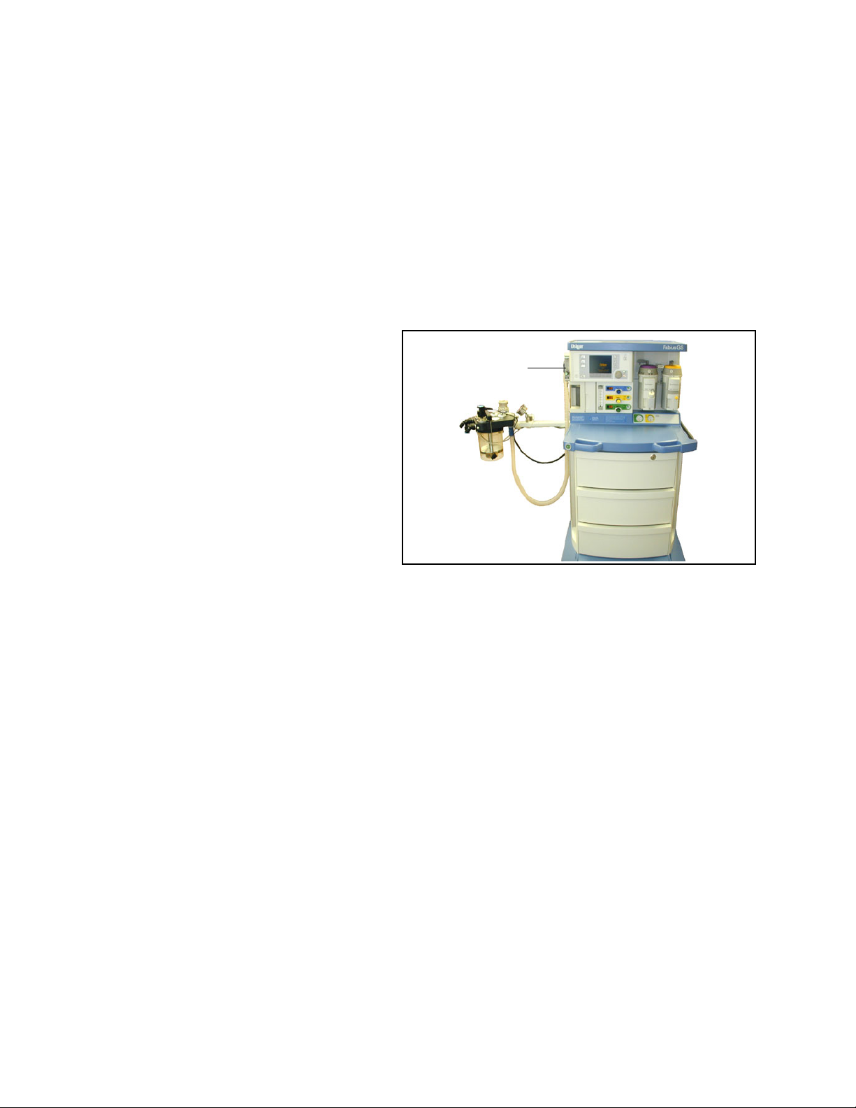
Typical Fabius GS Configuration
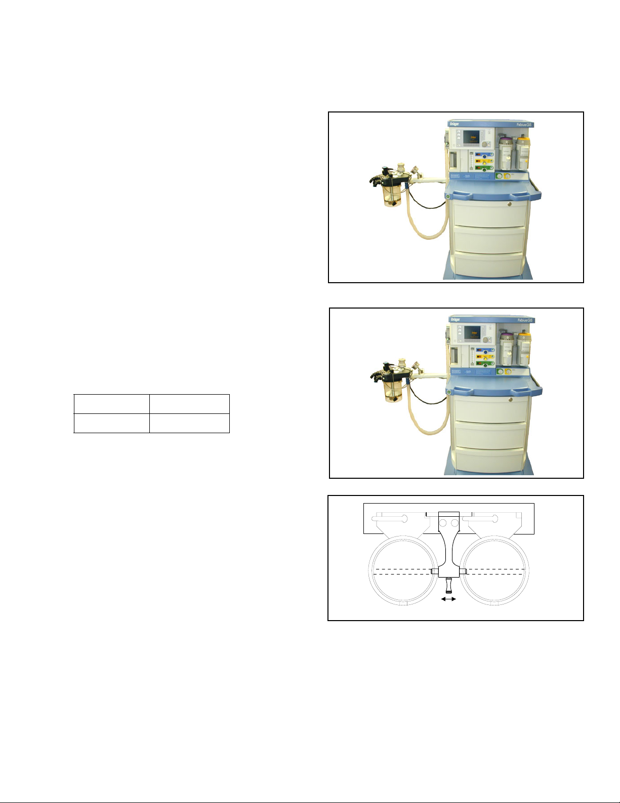
Figure 1. Fabius GS Anesthesia Machine The Fabius GS Inhalation Anesthesia Machine is a
modular system consisting of a basic gas-delivery
module with a variety of components and
configuration designs to meet the requirements of
various anesthesia delivery applications.
• 2-gas version (O2 and Air)
• 3-gas version (O2, N2O, and Air)
• pin index cylinder yokes and pressure gauges
Components
Figure 2. Dräger Vapor SystemVaporizers (Optional)
Rev: —
Part Number: 4117102-007
The Dräger Vapor® anesthetic agent vaporizers (1 in
Figure 2) are used to enrich the fresh gas with a
precisely metered quantity of vapor from the liquid
anesthetic agent being used, i.e. Isoflurane,
Halothane, Enflurane, or Sevoflurane.
When using a third-party Desflurane vaporizer:
220 V Mains Devapor*
110 V Mains D-Tec*
* Devapor and D-Tec are available through your local Desflurane
representative.
®
Interlock System
(Optional)
The Fabius GS is configured for two vaporizers. An
interlock system is used to ensure only one vaporizer
can be used at a time.
Note that the selector lever (1 in Figure 3) is shown in
the center position. This ensures that both vaporizers
are in the locked position. Also, this is the
recommended position for the selector lever when
moving the Fabius GS.
Moving the selector lever away from the desired
vaporizer allows that vaporizer to be utilized and the
other to be locked out of use.
1 1
Figure 3. Dräger Vapor Interlock SystemDräger Vapor
OP00520
1
Fabius GS Operator’s Manual 15
Page 22
RETURN TO THIS MANUAL'S TABLE OF CONTENTS
RETURN TO CD-ROM TABLE OF CONTENTS
Chapter 2 - Configurations and Components Components
Selectatec
™*
(Optional)
The interlock system for the Selectatec is built into
the vaporizers. When a vaporizer is selected for use,
the interlocking index pins will protrude from the
sides of the vaporizer thereby not allowing the
neighboring vaporizer to be opened. For more
specific information on the Selectatec, refer to the
Selectatec Vaporizer’s instruction manual.
*Selectatec™ is a registered trademark of Datex-Ohmeda.
For the delivery of a metered flow of pure oxygen (for
example, delivery of oxygen through a nasal
cannula), an optional auxiliary oxygen flowmeter
(1 in Figure 4) can be mounted on the left side of the
flowmeter bank. This flowmeter can be used when
the machine is turned off. A zero stop prevents
damage to the flow control valve seat.
Figure 4. Auxiliary Oxygen FlowmeterAuxiliary Oxygen Flowmeter (Optional)
1
16 Fabius GS Operator’s Manual
Part Number: 4117102-007
Rev: —
Page 23

RETURN TO THIS MANUAL'S TABLE OF CONTENTS
RETURN TO CD-ROM TABLE OF CONTENTS
Chapter 3 - Operating Concept Contents
Operating Concept
Contents
Overview ................................................................................................................. 19
Standard Function Controls ..................................................................................... 19
Home Key ............................................................................................................. 19
Mains Power Applied LED .................................................................................... 19
Selecting and Confirming ..................................................................................... 19
Tabletop Light Key ................................................................................................ 19
Cross-Functional Controls and Displays ................................................................. 20
Key LED Indicators ............................................................................................... 20
Rev: —
Setup Key ............................................................................................................. 20
Status Bar ............................................................................................................. 21
Monitoring ................................................................................................................ 22
Monitoring Controls .............................................................................................. 22
Monitoring Windows ............................................................................................. 23
Selecting/Setting Monitoring Functions ................................................................ 24
Ventilation ................................................................................................................ 26
Ventilation Controls ............................................................................................... 26
Ventilator Compliance Compensation .................................................................. 26
Ventilation Screens ............................................................................................... 27
Changing Ventilation Modes ................................................................................. 31
Selecting/Setting Ventilation Parameters ............................................................. 35
Fresh Gas Control ................................................................................................... 37
Fresh Gas Flow Monitoring Resolutions ................................................................. 38
Standard Resolution ............................................................................................. 38
High Resolution .................................................................................................... 38
Part Number: 4117102-007
Fabius GS Operator’s Manual 17
APL Valve ................................................................................................................ 39
Page 24

RETURN TO THIS MANUAL'S TABLE OF CONTENTS
RETURN TO CD-ROM TABLE OF CONTENTS
Page 25
RETURN TO THIS MANUAL'S TABLE OF CONTENTS
RETURN TO CD-ROM TABLE OF CONTENTS
Overview Chapter 3 - Operating Concept
Overview
This chapter provides an overview of the user
interface, which enables you to set and view
monitoring, ventilation, and status information using
the respective screens, windows, keys, soft keys,
and the rotary knob. See “Monitoring” on page 67 for
more information.
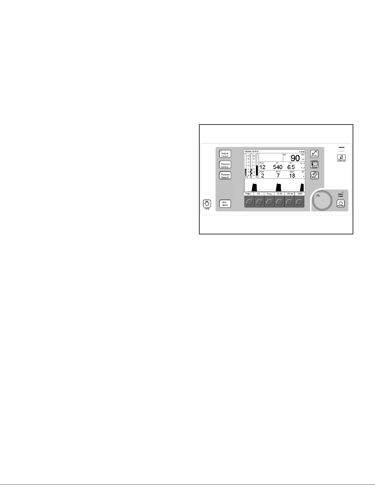
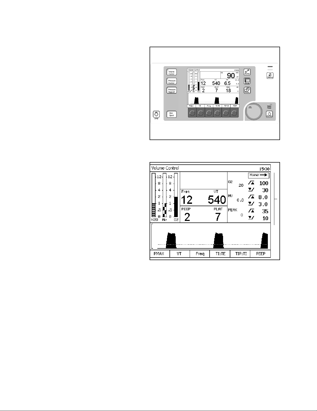
Figure 5. Ventilation Monitor Screen and System ControlsStandard Function Controls
Home Key
The Home key (1 in Figure 5) displays the main
screen (the screen in Figure 5) from anywhere in the
system.
Rev: —
Mains Power Applied LED
The Mains Power Applied LED (2 in Figure 5), when
illuminated, indicates that the machine is connected
to a Mains power source.
Selecting and Confirming
The rotary knob (3 in Figure 5) is used to select and
confirm functions by:
• Turning (Select)
Turning the rotary knob
• moves the cursor over the system
operating parameters or
• changes the value of a parameter that has
been confirmed for adjustment.
Note: This function is indicated in the examples
and instructions of this manual by
“select.”
• Pressing (Confirm)
Pressing the rotary knob either
1
4
2
3
• confirms the system operating parameter
to be adjusted or
• confirms the change to the selected
Part Number: 4117102-007
operating parameter.
Note: This function is indicated in the examples
and instructions of this manual by
“confirm.”
Tabletop Light Key
The Tabletop Light key (4 in Figure 5) turns on the
tabletop light.
Fabius GS Operator’s Manual 19
Page 26
RETURN TO THIS MANUAL'S TABLE OF CONTENTS
RETURN TO CD-ROM TABLE OF CONTENTS
Chapter 3 - Operating Concept Cross-Functional Controls and Displays
Figure 6. Ventilation Monitor Screen and System ControlsCross-Functional Controls and
Displays
Cross-functional controls and displays are used for
both monitoring and ventilation functions.
Key LED Indicators
LED indicators (1 in Figure 6) within keys (Volume
Control, Pressure Control, Pressure Support, Man/
Spont, Alarm Silence, and Standby) illuminate when
that mode or function is selected and operating.
The Setup key is 2 in Figure 6.
1
2
3
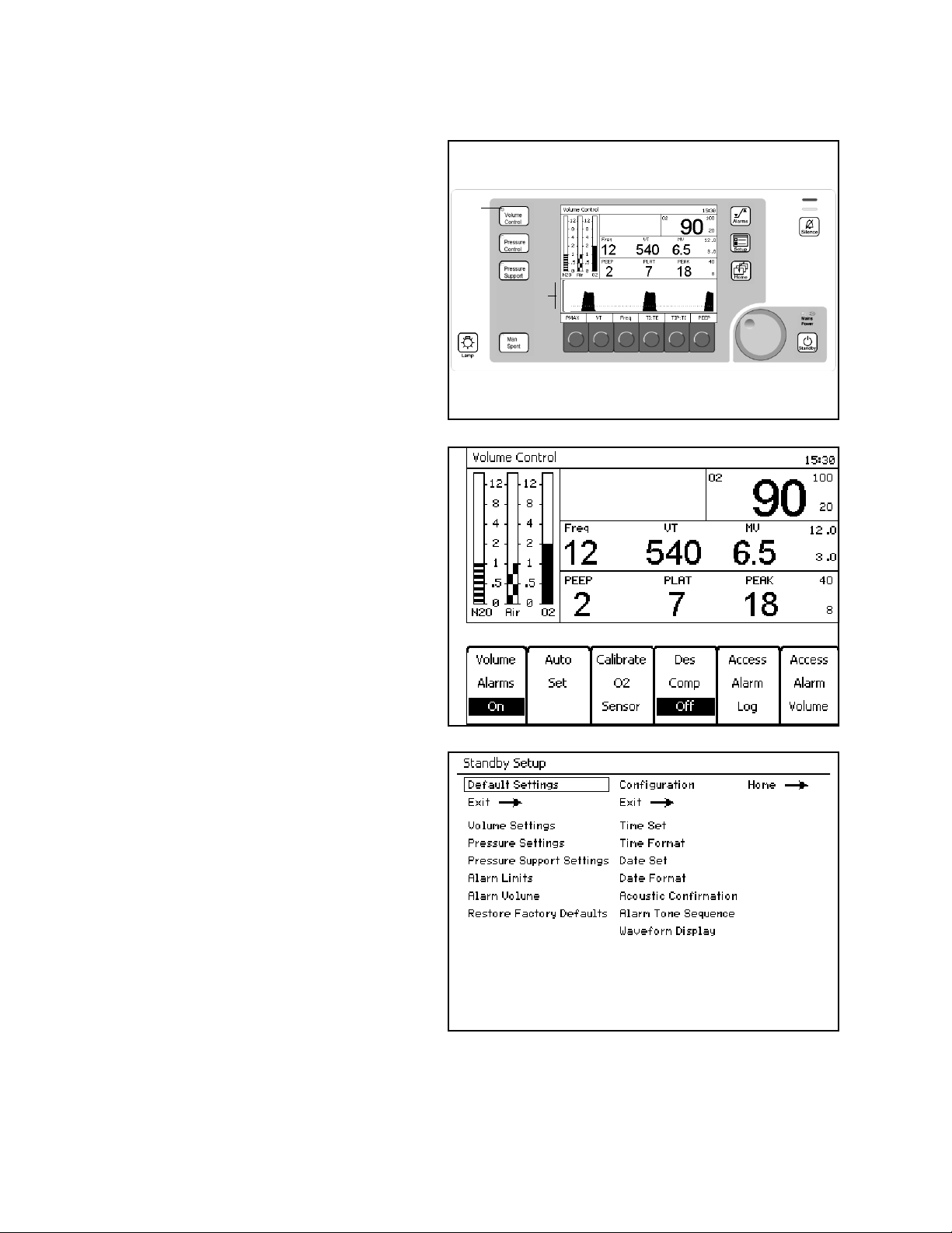
Figure 7. Setup WindowSetup Key
Pressed During A Ventilation Mode
The Setup window (1 in Figure 7) replaces the
Waveform area (3 in Figure 6).
The Setup window enables you to
• perform ventilation functions and
• view and change monitoring settings.
Note: The Volume Alarms On/Off soft key label
does not appear in ManSpont mode because
it is selectable on the ManSpont screen
(Figure 24 on page 30).
The Standby Setup screen (Figure 8) appears. The
Standby Setup screen enables you to define site
defaults and configuration.
1
Figure 8. Standby Setup ScreenPressed During Standby Mode
Part Number: 4117102-007
Rev: —
20 Fabius GS Operator’s Manual
Page 27
RETURN TO THIS MANUAL'S TABLE OF CONTENTS
RETURN TO CD-ROM TABLE OF CONTENTS
Cross-Functional Controls and Displays Chapter 3 - Operating Concept
Figure 9. Status BarStatus Bar
The following numbers in parenthesis refer to
Figure 9.
Mode Display (1)
Displays the active ventilator mode.
Alarm Silence Status (2)
Displays the time remaining for alarm silence when
the Silence Alarms key is pressed.
Battery Power Level (3)
Displays the status of the reserve power.
Time (4)
Displays the time.
1234
Rev: —
Part Number: 4117102-007
Fabius GS Operator’s Manual 21
Page 28
RETURN TO THIS MANUAL'S TABLE OF CONTENTS
RETURN TO CD-ROM TABLE OF CONTENTS
Chapter 3 - Operating Concept Monitoring
Figure 10. Ventilation Monitor Screen and System ControlsMonitoring
Monitoring Controls
LED Indicators
LED lamps (1 in Figure 10) in the upper right corner
of the control panel indicate the degree of urgency of
currently active alarms.
• Warning — Red Blinking
• Caution — Yellow Blinking
• Advisory — Yellow Continuous
Silence Alarms Key
The Silence Alarms key (2 in Figure 10) silences all
active alarm tones for 2 minutes. It resets the silence
time for two minutes each time the key is pressed.
The Alarm Limit key (3 in Figure 10) displays the
Alarm Limits window (1 in Figure 11), which appears
in the same location on all mode screens.
Setup Key
The Setup key (4 in Figure 10) is a cross-functional
control. See “Setup Key” on page 20.
1
3
2
4
Figure 11. Alarm Limit Configure WindowAlarm Limit Key
1
22 Fabius GS Operator’s Manual
Part Number: 4117102-007
Rev: —
Page 29
RETURN TO THIS MANUAL'S TABLE OF CONTENTS
RETURN TO CD-ROM TABLE OF CONTENTS
Monitoring Chapter 3 - Operating Concept
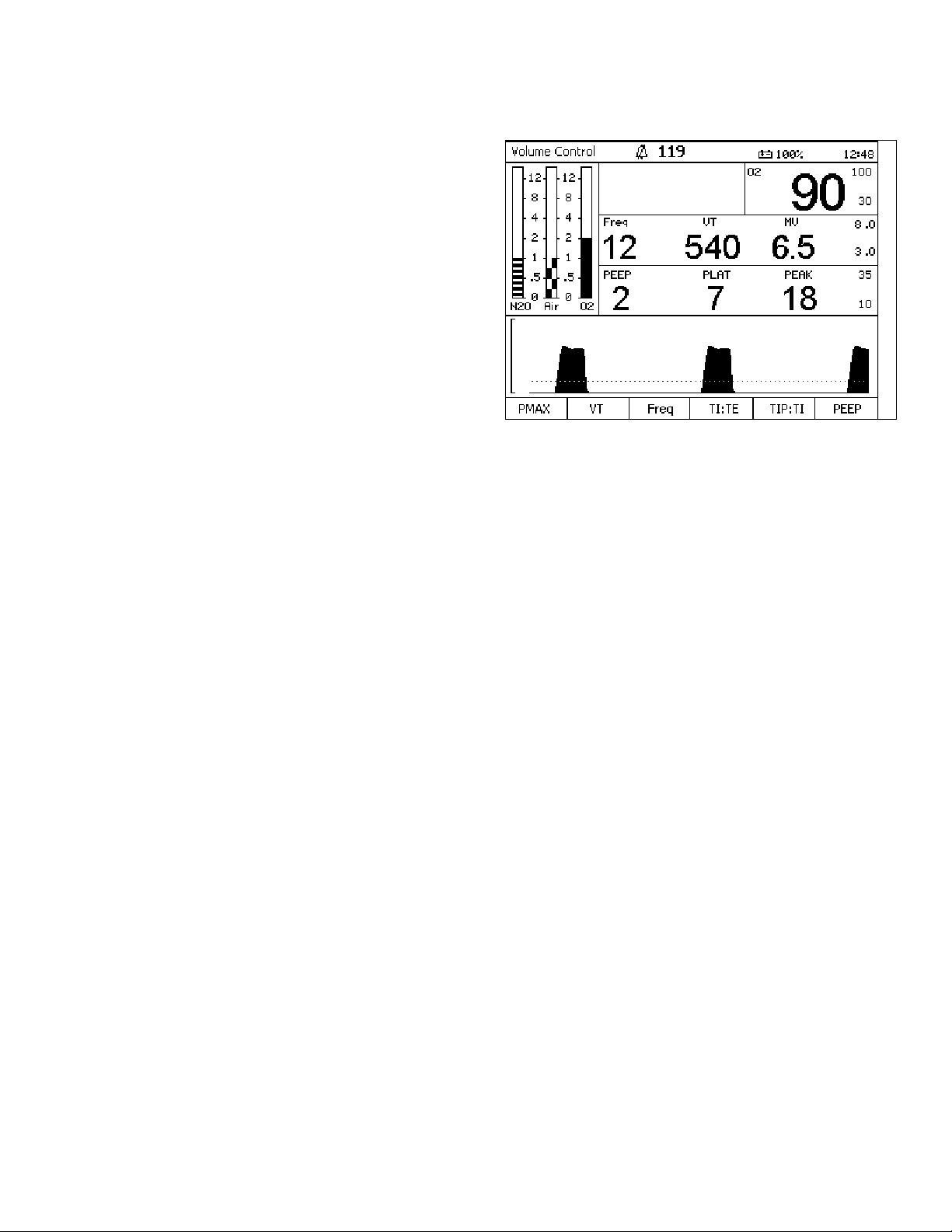
Figure 12. Monitor ScreenMonitoring Windows
The following numbers in boldface refer to
Figure 12.
Alarm Window
The Alarm window (1) displays up to four of the
highest priority alarms.
1
2
3
Oxygen Monitor Window
The Oxygen Monitor window (2) displays the
inspiratory oxygen concentration in units of percent
(%). It also displays the oxygen alarm limits in the farright section of this window.
Respiratory Volume Monitor Window
The Respiratory Volume Monitor window (3) displays
the patient's frequency (breaths per minute) or
respiratory rate, tidal volume, minute volume, the
minute volume high alarm limit, and the minute
volume low alarm limit.
Breathing Pressure Monitor Window
The Breathing Pressure Monitor window (4) displays
the patient's positive end expiratory pressure
(PEEP), mean airway pressure (MEAN) or plateau
airway pressure (PLAT), and peak airway pressure
(PEAK).
Breathing Pressure Trace Window
The Breathing Pressure Trace window (5) displays a
trace, or waveform, of the patient's breathing
pressure.
4
5
Rev: —
Part Number: 4117102-007
Fabius GS Operator’s Manual 23
Page 30
RETURN TO THIS MANUAL'S TABLE OF CONTENTS
RETURN TO CD-ROM TABLE OF CONTENTS
Chapter 3 - Operating Concept Monitoring
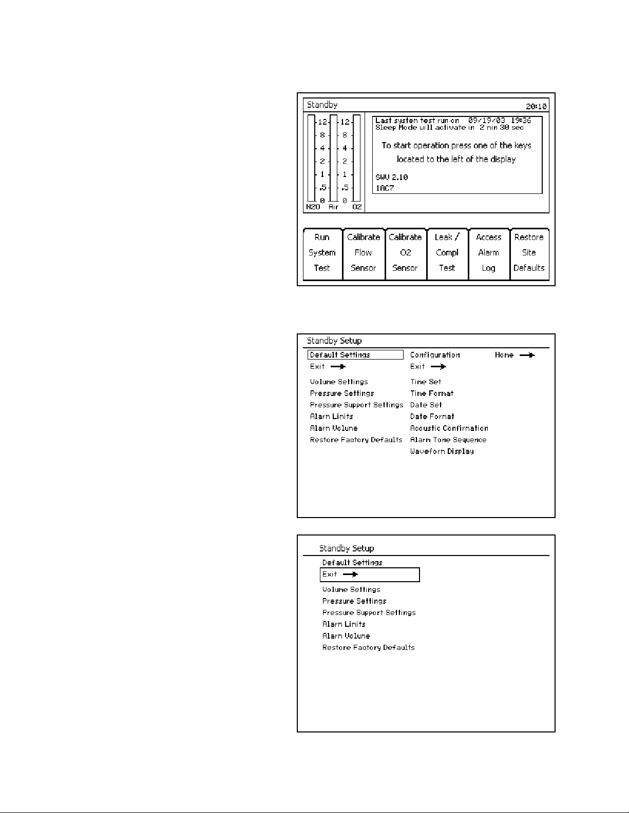
Figure 13. Standby ScreenSelecting/Setting Monitoring Functions
The following example describes changing alarm
limits on the Standby Setup Screen.
Example
1. Press the Setup key while the Standby Screen
(Figure 13) is active. The Standby Setup screen
(Figure 14) replaces the Standby Screen.
2. The rotary knob enables you to select the
“Default Settings” or “Configuration” label.
Select and confirm the “Default Settings” label.
The Default Settings column is selected
(Figure 15).
Note: Selecting and confirming the return arrow
(1 in Figure 14) will deactivate the Standby
Setup screen and activate the Standby
screen (Figure 13).
Figure 14. Standby Setup ScreenNote: Selecting and confirming the return arrow
(1 in Figure 15) will deselect the Default
Settings column and reselect the Default
Settings label as in Figure 14.
1
Figure 15. Standby Setup Screen Default Settings Selected
1
24 Fabius GS Operator’s Manual
Part Number: 4117102-007
Rev: —
Page 31

RETURN TO THIS MANUAL'S TABLE OF CONTENTS
RETURN TO CD-ROM TABLE OF CONTENTS
Monitoring Chapter 3 - Operating Concept
Figure 16. Standby Setup Screen Default Alarm Limits3. Select and confirm the “Alarm Limits” label.
The Default Alarm Limits window appears
(1 in Figure 16).
1
Rev: —
4. Select the alarm limit value that needs to change
(Figure 17).
5. Confirm the alarm limit value and select a new
value for the alarm limit (ex., in Figure 18, the
value was changed from 30 to 25).
6. Confirm the new value for the alarm limit.
The new alarm limit value is saved and the cursor
moves over the return arrow.
Figure 17. Standby Setup Screen Default Alarm Limits
Select
Figure 18. Standby Setup Screen Default Alarm Limits
Confirm
Part Number: 4117102-007
Fabius GS Operator’s Manual 25
Page 32

RETURN TO THIS MANUAL'S TABLE OF CONTENTS
RETURN TO CD-ROM TABLE OF CONTENTS
Chapter 3 - Operating Concept Ventilation
Figure 19. Ventilation Monitor Screen and System ControlsVentilation
Note: Pressure Control and Pressure Support
ventilation modes, described in this manual,
are optional.
1
Ventilation Controls
The following numbers in boldface refer to Figure 19.
Ventilation Mode Keys
Ventilation modes are selected by pressing one of
the ventilation mode keys (1, 2, 3, 4) and are
confirmed by pressing the rotary knob. If the
selection is not confirmed, the ventilation mode will
not change.
Setup Key
The Setup key (5) is a cross-functional control. See
“Setup Key” on page 20.
2
3
4
7
5
6
Standby Key
The Standby key (6) switches the ventilator to
standby mode.
Monitoring and alarms are turned off and the
ventilator stops.
Soft Keys
Soft keys (7) select ventilation parameters and
functions.
Ventilator Compliance Compensation
Ventilator compliance compensation is continuously
applied during Volume Control so that the tidal
volume delivered to the patient corresponds to the Vt
setting. Ventilator compliance is determined during
the leak and compliance test performed from the
Standby mode. To have compliance compensation
work accurately, it is important that the patient hoses
used during the leak/compliance test match the type
of hoses used during the procedure.
Note: When the ventilator settings for Volume
Control cause the ventilator to operate at its
limits of performance, it is not possible for
the Fabius GS to apply compliance
compensation. If the ventilator's performance
limit is reached, it is not possible to
increment the Vt setting via the Volume
Control Settings window.
Part Number: 4117102-007
Rev: —
26 Fabius GS Operator’s Manual
Page 33

RETURN TO THIS MANUAL'S TABLE OF CONTENTS
RETURN TO CD-ROM TABLE OF CONTENTS
Ventilation Chapter 3 - Operating Concept
Figure 20. Ventilation Monitor Screen and System ControlsVentilation Screens
Soft Key Labels
The following numbers in boldface refer to Figure 20.
Each soft key (1) is associated with a ventilation
parameter (2) that is associated with a specific
ventilation mode (3).
Figure 21. Volume Control Ventilation ScreenVolume Control Mode
The following soft key labels appear from left to right
along the bottom of the Volume Control screen.
See Figure 21.
3
2
1
Rev: —
Part Number: 4117102-007
• P
MAX (maximum ventilation pressure).
The range for P
15 to 70 cmH
MAX is
O.
2
The factory default value is
40 cmH
O.
2
• VT (tidal volume).
The range for VT is 20 mL to 1400 mL.
The factory default value is 600 mL.
• Freq (ventilation frequency).
The range for Frequency is 4 bpm to 60 bpm.
The factory default value is 12 bpm.
• T
I:TE (time ratio between inspiration time and
expiration time phases).
The range for T
I:TE is 4:1 to 1:4.
The factory default value is 1:2.
• T
IP:TI (relative inspiratory pause).
The range for T
IP:TI is 0% to 50%.
The factory default value is 10%.
• PEEP (positive end expiratory pressure).
The range for PEEP is
0 to 20 cmH
2
O.
The factory default value is
0 cmH
O.
2
Fabius GS Operator’s Manual 27
Page 34

RETURN TO THIS MANUAL'S TABLE OF CONTENTS
RETURN TO CD-ROM TABLE OF CONTENTS
Chapter 3 - Operating Concept Ventilation
Figure 22. Pressure Control Ventilation ScreenPressure Control Mode
The following soft key labels appear from left to right
along the bottom of the Pressure Control screen.
See Figure 22.
• PINSP (inspiratory pressure setting).
The range for PINSP is
5 to 60 cmH
The factory default value is 15.
• Freq (ventilation frequency).
The range for Frequency is 4 bpm to 60 bpm.
The factory default value is 12 bpm.
• TI:TE (time ratio between inspiration and
expiration phases).
The range for TI:TE is 4:1 to 1:4.
The factory default value is 1:2.
• Insp Flow (maximum rate at which the piston
travels upward to create the target pressure).
The range for Insp Flow is
10 L/min to 75 L/min.
The factory default value is 30 L/min.
2
O.
• PEEP (positive end expiratory pressure).
The range for Peep is
0 to 20 cmH
2
O.
The factory default value is
0 cmH
O.
2
Pressure Support Mode
Pressure Support ventilation is intended to reduce
the work of breathing and is indicated for use only in
patients who are breathing spontaneously. Patients
who are not making spontaneous breathing efforts
are not candidates for Pressure Support ventilation.
Caution: Pressure Support ventilation is
triggered by the patient's
spontaneous effort to breathe. Most
anesthetic agents will cause patients
to have reduced ventilatory
responses to carbon dioxide and to
hypoxemia. Therefore, patient
triggered modes of ventilation may
not produce adequate ventilation.
Additionally, the use of
neuromuscular blocking agents will
interfere with patient triggering.
Part Number: 4117102-007
Rev: —
Apnea Ventilation is a feature within Pressure
Support ventilation. To enable Apnea Ventilation,
adjust the Freq Min setting to a value other than
“OFF.” If the detected patient spontaneous breathing
rate falls below the set value, the ventilator
automatically delivers a Pressure Support breath.
28 Fabius GS Operator’s Manual
Page 35

RETURN TO THIS MANUAL'S TABLE OF CONTENTS
RETURN TO CD-ROM TABLE OF CONTENTS
Ventilation Chapter 3 - Operating Concept
When delivering Apnea Ventilation, the Fabius GS
uses the Pressure Support settings for PSUP, Insp
Flow, and PEEP.
If two consecutive Apnea Ventilation breaths occur,
the Caution message APNEA VENTILATION !!
appears in the Alarm window. The alarm is cleared
when a spontaneous breath is detected.
Figure 23. Pressure Support Ventilation ScreenThe following soft key labels appear from left to right
along the bottom of the Pressure Support screen.
See Figure 23.
• PSUP (inspiratory pressure setting).
The range for PSUP is
3 to 20 cmH
The factory default value is 10.
• Freq Min (minimum ventilation frequency
setting for Apnea Ventilation)
The range for Freq Min. is
3 to 20 bpm and “OFF.”
The factory default value is 3.
2O.
Rev: —
Part Number: 4117102-007
• Trigger (Trigger Level - patient inspiratory flow
threshold for Pressure Support).
The range for Trigger is
2 to 15 L/min.
The factory default value is 2.
• Insp Flow (maximum rate at which the piston
travels upward to create the target pressure).
The range for Insp Flow is
10 L/min to 85 L/min.
The factory default value is 30 L/min.
• PEEP (positive end expiratory pressure).
The range for Peep is
0 to 20 cmH
2O.
The factory default value is
0 cmH
2O.
Fabius GS Operator’s Manual 29
Page 36

RETURN TO THIS MANUAL'S TABLE OF CONTENTS
RETURN TO CD-ROM TABLE OF CONTENTS
Chapter 3 - Operating Concept Ventilation
Figure 24. ManSpont Ventilation ScreenManSpont Mode
The “Apnea Pressure” and “Volume Alarms” labels
appear to the left of their ON/OFF label on the bottom
of the ManSpont screen. See Figure 24. Pressing the
ON/OFF soft key turns the applicable alarm(s) “ON”
or “OFF.”
Figure 25. Standby ScreenStandby Mode
The following soft key labels appear from left to right
along the bottom of the Standby screen.
See Figure 25.
• Run System Test
• Calibrate Flow Sensor
• Calibrate O2 Sensor
• Leak / Compl Test
• Access Alarm Log
• Restore Site Defaults
See “Standby Screen” on page 95 for details.
The Flow Meter Monitor window is a graphical
display of the flow rates of O
, Air, and N2O (L/min)
2
(1 in Figure 26).
Note: On some non-U.S. units of the Fabius GS,
the O2 and N2O virtual flow tubes have
changed positions.
Figure 26. Flow Meter Monitor WindowFlow Meter Monitor Window
Part Number: 4117102-007
1
Rev: —
30 Fabius GS Operator’s Manual
Page 37

RETURN TO THIS MANUAL'S TABLE OF CONTENTS
RETURN TO CD-ROM TABLE OF CONTENTS
Ventilation Chapter 3 - Operating Concept
Figure 27. Ventilator Mode Change Confirmation Changing Ventilation Modes
Volume Control and Pressure Control
The following example describes changing
• from the present ventilation mode “Volume”
(1 in Figure 27)
• to the desired ventilation mode “Pressure”
(2 in Figure 27) with the desired ventilation
settings (3 in Figure 27).
1. Press the Pressure Control key.
The LED associated with this key starts blinking
(
4 in Figure 27). It remains blinking until the
selected mode of operation is confirmed.
A message appears (
5 in Figure 27) that
provides instructions to confirm the mode
change.
4
5
6
1
2
3
Rev: —
The Waveform window is replaced by the
Ventilator Settings window (
6 in Figure 27)
(Volume and Pressure modes only).
2. If the ventilation settings are correct, confirm the
mode change.
3. If the ventilation settings are not correct, for each
parameter that needs to change, press the
corresponding soft key, select the correct value,
and confirm the change.
4. When the parameter changes are completed,
confirm the ventilation mode change.
After the mode change is confirmed, the
Pressure Control key LED switches from blinking
to constantly on, the ventilator switches to the
selected operating mode, and the waveform is
restored after a short delay.
Part Number: 4117102-007
Fabius GS Operator’s Manual 31
Page 38

RETURN TO THIS MANUAL'S TABLE OF CONTENTS
RETURN TO CD-ROM TABLE OF CONTENTS
Chapter 3 - Operating Concept Ventilation
Figure 28. Ventilator Mode Change SettingsVentilator Setting Selection
Selected ventilator settings for the new mode of
operation are automatically derived from the settings
and performance of the last confirmed automatic
ventilation mode. Settings affected in the new mode
will be highlighted (1 in Figure 28).
The settings for Freq., TI : TE, and PEEP are taken
directly from the settings used in the former mode as
applicable.
When changing from Volume Control to Pressure
Control, Pinsp is set to the Plateau pressure
developed in Volume Control.
When changing from Volume Control or Pressure
Support to Pressure Control, the suggested value for
Insp. Flow is either the last used value or the site
default value.
When changing from Pressure Control to Volume
Control, VT is set by dividing the last minute volume
by the respiratory rate.
1
When changing from Pressure Control to Volume
Control, the suggested value for TIP : TI is either the
last used value or the site default value.
When changing from Pressure Control to Volume
Control, PMAX is set 10 cmH2O higher than the
plateau pressure developed during Pressure Control.
When changing from Volume Control or Pressure
Control to Pressure Support, the suggested value for
Insp. Flow is either the last used value or the site
default value.
When changing from Volume Control or Pressure
Control to Pressure Support, the suggested value for
PSUP is either the last used value or the site default
value.
When changing from Volume Control or Pressure
Control to Pressure Support, the suggested value for
Trigger is either the last used value or the site
default value.
Part Number: 4117102-007
Rev: —
32 Fabius GS Operator’s Manual
Page 39

RETURN TO THIS MANUAL'S TABLE OF CONTENTS
RETURN TO CD-ROM TABLE OF CONTENTS
Ventilation Chapter 3 - Operating Concept
Figure 29. Ventilator Mode Change to Man SpontManSpont
ManSpont (Manual/Spontaneous) is a non-automatic
mode of ventilation. However, the ventilation monitor
and alarms are still operational. In ManSpont mode,
the ventilator piston is moved to its top-most position
to minimize system compliance. Manual ventilation
(with APL valve pressure limit) can be delivered with
the APL valve switch in the MAN position.
Spontaneous ventilation (APL valve wide-open) can
occur with the APL valve in the SPONT position.
The following examples describe changing
1
3
4
Rev: —
• from the present ventilation mode “Volume”
(1 in Figure 29)
• to the desired ventilation mode “ManSpont”
(1 in Figure 30).
1. Press the ManSpont key.
The LED associated with this key starts blinking
(
2 in Figure 29). It remains blinking until the
selected mode of operation is confirmed.
The Waveform window is replaced by the
ManSpont window (
A message appears (
provides instructions to confirm the mode
change.
2. Confirm the mode change. The ManSpont
screen is activated (Figure 30).
After the mode change is confirmed, the
ManSpont key LED switches from blinking to
constantly on and the waveform is restored after
a short delay.
3. Rotate the APL valve knob fully counterclockwise
to release pressure for spontaneous ventilation.
4. Set the appropriate fresh gas flow.
3 in Figure 29).
4 in Figure 29) that
2
Figure 30. ManSpont Ventilation ScreenSpontaneous Breathing
Note: The ManSpont screen enables you to
turn the Apnea Pressure alarm and
Volume alarms ON or OFF.
Part Number: 4117102-007
Fabius GS Operator’s Manual 33
Page 40

RETURN TO THIS MANUAL'S TABLE OF CONTENTS
RETURN TO CD-ROM TABLE OF CONTENTS
Chapter 3 - Operating Concept Ventilation
Figure 31. Ventilator Mode Change to Man SpontManual Ventilation
Note: In ManSpont mode, the apnea volume timer
countdown for caution alarms changes from
15 seconds to 30 seconds, and for warning
alarms from 30 seconds to 60 seconds.
1. Press the ManSpont key.
The LED associated with this key starts blinking
(
1 in Figure 31). It remains blinking until the
selected mode of operation is confirmed.
The Waveform window is replaced by the
ManSpont window (
A message appears (
provides instructions to confirm the mode
change.
screen is activated (Figure 32).
After the mode change is confirmed, the
ManSpont key LED switches from blinking to
constantly on and the waveform is restored after
a short delay.
2 in Figure 31).
3 in Figure 31) that
2
1
Figure 32. ManSpont Ventilation Screen2. Confirm the mode change. The ManSpont
3
Note: The ManSpont screen enables you to
turn the Apnea Pressure alarm and
Volume alarms ON or OFF.
3. Adjust the APL valve knob to set the appropriate
value for the maximum ventilation pressure (see
“APL Valve” on page 39).
4. Press the O
the bag.
5. Set the fresh gas flow.
6. Start manual ventilation.
2 flush button, as required, to inflate
Part Number: 4117102-007
Rev: —
34 Fabius GS Operator’s Manual
Page 41

RETURN TO THIS MANUAL'S TABLE OF CONTENTS
RETURN TO CD-ROM TABLE OF CONTENTS
Ventilation Chapter 3 - Operating Concept
Figure 33. Volume Ventilator Settings WindowSelecting/Setting Ventilation Parameters
1. In Volume Control mode, press the Volume
Control key. The Volume Control Ventilation
Settings window (
Waveform window.
In Pressure Control mode, press the Pressure
Control key. The Pressure Control Ventilation
Settings Window (
Waveform window.
In Pressure Support mode, press the Pressure
Support key. The Pressure Support Ventilation
Settings Window (
Waveform window.
1 in Figure 33) replaces the
1 in Figure 34) replaces the
1 in Figure 35) replaces the
1
Figure 34. Pressure Control Ventilator Settings Window
Rev: —
Part Number: 4117102-007
1
Figure 35. Pressure Support Ventilator Settings Window
1
Fabius GS Operator’s Manual 35
Page 42

RETURN TO THIS MANUAL'S TABLE OF CONTENTS
RETURN TO CD-ROM TABLE OF CONTENTS
Chapter 3 - Operating Concept Ventilation
Figure 36. Volume Control Ventilator Label SelectedThe following example continues in Volume Control
mode.
2. Press the VT (tidal volume) soft key.
The Ventilator Settings window appears with the
VT parameter label highlighted (1 in Figure 36).
3. Select a new VT parameter setting.
4. Confirm the new VT parameter setting.
Note: Once the Ventilator Settings window is
activated, it will return to the Waveform
window if 15 seconds pass and neither the
rotary knob nor a soft key is pressed.
If the Home key is pressed, the Ventilator
Settings window will return to the Waveform
window.
In either case, the ventilation parameter will
remain as it was before it was activated in
the Ventilator Settings window.
1
36 Fabius GS Operator’s Manual
Part Number: 4117102-007
Rev: —
Page 43

RETURN TO THIS MANUAL'S TABLE OF CONTENTS
RETURN TO CD-ROM TABLE OF CONTENTS
Fresh Gas Control Chapter 3 - Operating Concept
Fresh Gas Control
The following numbers in boldface refer to Figure 37. Flow is increased when the flow control knobs (N2O (1),
AIR (2), O
The total flow meter (4) displays the flow measurement of all of the applied gases combined.
(3)) are turned counterclockwise.
2
Note: The total flow meter is calibrated for a 50/50 mixture of N
O and O2. The accuracy of the flow meter may
2
degrade with other gas mixtures. (See the Technical Data section for specifications.)
The total flow meter serves two purposes. The total flow meter provides a reference of the total fresh gas applied
to the breathing circuit. (Flow rate measurements for each individual gas; N
O, Air, and O2; are provided by their
2
respective electronic flow indicator.)
Should a fault develop in the electronic flow sensing, digital display, or power circuitry, the total flow meter is still
functional. The measurement will indicate the total flow rate prior to the fault condition.
To adjust the fresh gas ratios while under the fault condition, shut off all flows (O
each gas flow individually. For example, start with 2 L/min O
If 1 L/min of N
plus 1 L/min N
The electronic fresh gas flow indicators (N
O is needed, open the N2O flow control knob until the total flow meter reads 3 L/min - 2 L/min O2
2
O.
2
O (5), AIR (6), O2 (7)) display the flow measurement of each gas.
2
. The total flow meter will read 2 L/min.
2
may be left on), and then restore
2
Note: The electronic fresh gas flow meters are altitude corrected.
The central supply pressure indicators (N
gas entering the Fabius GS from the facility’s pipeline.
The cylinder gauges (O
(11), Air (12)) display the pressure measurement of each gas entering the Fabius GS
2
from cylinders.
The O2 Low Supply Pressure Alarm LED (13) flashes when the O2 supply is below the factory set minimum
pressure, nominally 20 psi (1.4 bar).
Figure 37. Flowmeter and Pressure Gauge Assembly
O (8), AIR (9), O2 (10)) display the pressure measurement of each
2
Rev: —
Part Number: 4117102-007
4
TOTAL
FLOW
±15% FS
5
6
7
L/min
L/min
L/min
13
1
2
3
Pipeline
N O
2
Pipeline
AIR
Pipeline
O
2
8
9
10
11 12
Cylinder
Pressure
O
2
Air
Fabius GS Operator’s Manual 37
Page 44

RETURN TO THIS MANUAL'S TABLE OF CONTENTS
RETURN TO CD-ROM TABLE OF CONTENTS
Chapter 3 - Operating Concept Fresh Gas Flow Monitoring Resolutions
Figure 38. Standard Resolution Fresh Gas Flow MonitoringFresh Gas Flow Monitoring
Resolutions
The Fabius GS can be configured by your Local
Authorized Service Organization to display fresh gas
flow rates either in a standard resolution mode or in a
high resolution mode.
Standard Resolution
If standard resolution is configured (Figure 38), the
numeric displays (LEDs) for the fresh gas flow rates
support 100 ml/min. increments (format xx.x l/min.)
and the flow meters on the monitor screen indicate a
range of 0 to 12 l/min.
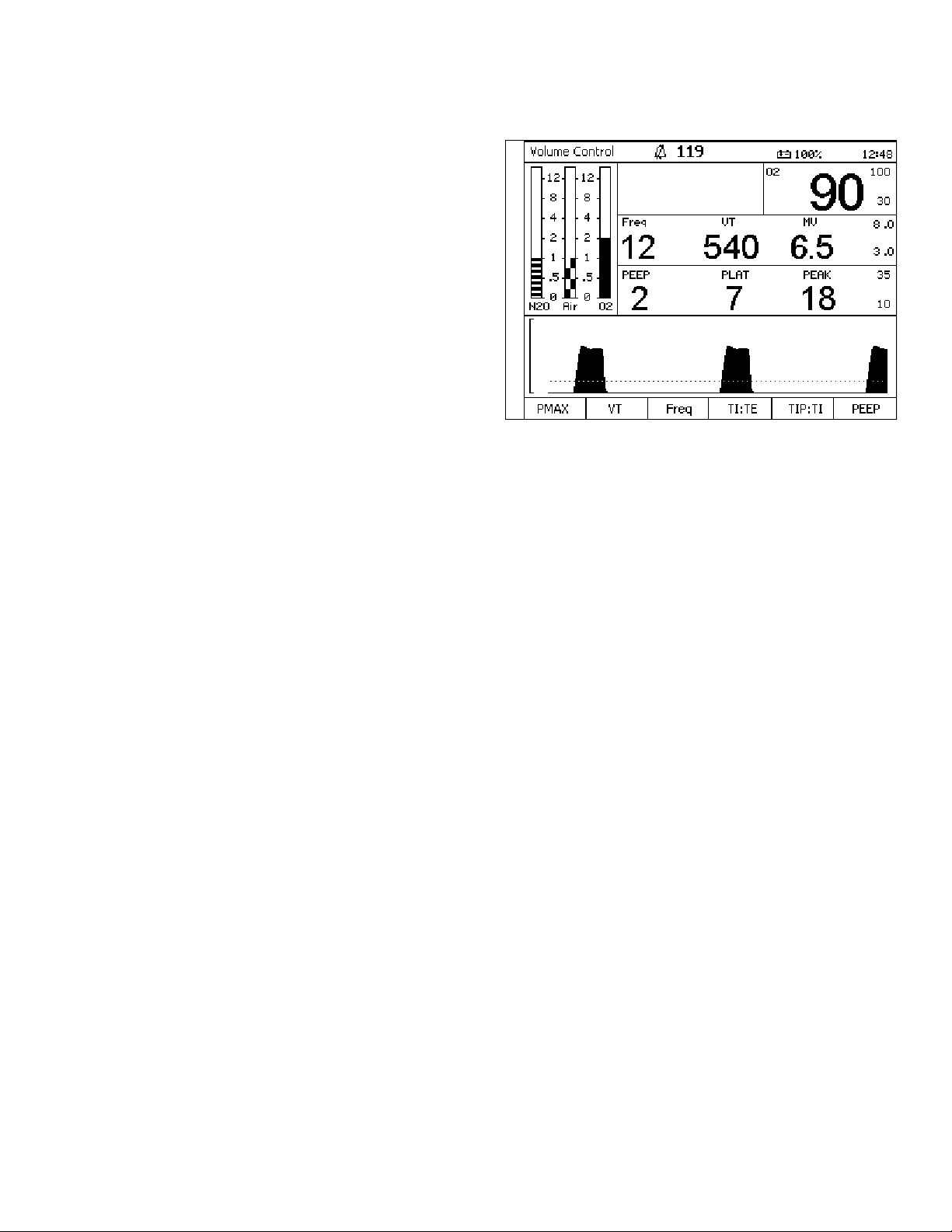
Figure 39. High Resolution Fresh Gas Flow MonitoringHigh Resolution
If high resolution is configured (Figure 39), the
numeric displays (LEDs) for the fresh gas flow rates
support 10 ml/min. increments (format x.xx l/min.)
and the flow meters on the monitor screen indicate a
range of 0 to 10 l/min. with an emphasis on
resolution at the lower end of the scale.
High-resolution data is displayed when all individual
gas flows are below 9.99 l/min.
Switching to standard resolution occurs when the
highest flow rate is greater than 9.99 l/min.
Switching to high resolution occurs when the highest
flow rate drops below 9.00 l/min.
Part Number: 4117102-007
Rev: —
38 Fabius GS Operator’s Manual
Page 45

RETURN TO THIS MANUAL'S TABLE OF CONTENTS
RETURN TO CD-ROM TABLE OF CONTENTS
APL Valve Chapter 3 - Operating Concept
Figure 40. APL VavleAPL Valve
The following numbers in boldface refer to Figure 40.
The APL valve (1) has two functions. It limits the
maximum pressure during manual ventilation. It also
exhausts excess gas into the scavenger system
during manual and spontaneous ventilation.
The APL valve is connected to the patient airway
through the ventilator. It functions only when the
ventilator is in ManSpont mode or ventilator override
condition.
The APL valve has a labeled knob (2) for selecting
between spontaneous and manual modes of
ventilation and for indicating approximate pressure
settings.
When the APL valve knob is rotated fully
counterclockwise, pressure is released for
spontaneous ventilation. Spontaneous ventilation
automatically eliminates both resistance to patient
exhalation and the need to readjust back pressure.
2
1
Rev: —
Part Number: 4117102-007
In manual mode, the APL valve knob can be rotated
to change the pressure threshold at which gas will
flow through the valve and into the scavenging
system. Clockwise rotation of the APL valve knob
increases the pressure threshold, and
counterclockwise rotation of the APL valve knob
decreases the pressure threshold. Lifting the top of
the APL valve knob will temporarily relieve pressure.
Note: The APL valve is automatically excluded
from the breathing circuit whenever an
automatic ventilator mode is selected.
Fabius GS Operator’s Manual 39
Page 46

RETURN TO THIS MANUAL'S TABLE OF CONTENTS
RETURN TO CD-ROM TABLE OF CONTENTS
Page 47

RETURN TO THIS MANUAL'S TABLE OF CONTENTS
RETURN TO CD-ROM TABLE OF CONTENTS
Chapter 4 - Preparation Contents
Preparation
Contents
Activating the Battery .............................................................................................. 43
Gas Supply .............................................................................................................. 43
Medical Gas Pipeline Supply of O2, N2O, and AIR ................................................ 43
Cylinders with Pin-index Mounting .......................................................................... 44
Electrical Supply ...................................................................................................... 45
Attaching Manual (Ambu) Ventilation Bag ............................................................... 45
Preparing the Ventilator ........................................................................................... 46
Ventilator Safety Features ....................................................................................... 46
Rev: —
Attaching the CO2 Absorber onto the Compact Breathing System ......................... 46
Attaching the Inspiratory Valve ................................................................................ 47
Attaching the Expiratory Valve ................................................................................. 47
Attaching the Adjustable Pressure Limiting (APL) Valve ......................................... 47
Inserting the Flow Sensor ........................................................................................ 48
Attaching the Waste Gas Outlet Port ....................................................................... 48
Connecting the Compact Breathing System ............................................................ 48
Connecting the Breathing Hoses ............................................................................. 49
Inserting A New O2 Sensor Capsule ....................................................................... 49
Connecting the O2 Sensor ...................................................................................... 50
Connecting the Pressure Sensor ............................................................................ 50
Connecting the Breathing Pressure Gauge ............................................................. 51
Connecting the APL Bypass and Peep/PMAX Hoses ............................................. 51
Connecting the Flow Sensor ................................................................................... 52
Installing Anesthetic Gas Scavenging Hose to the Compact Breathing System ..... 52
Scavenger System for Fabius GS ........................................................................... 53
Part Number: 4117102-007
Fabius GS Operator’s Manual 41
Daily and Preuse Checkout Form ........................................................................... 53
Page 48

RETURN TO THIS MANUAL'S TABLE OF CONTENTS
RETURN TO CD-ROM TABLE OF CONTENTS
Page 49

RETURN TO THIS MANUAL'S TABLE OF CONTENTS
RETURN TO CD-ROM TABLE OF CONTENTS
Activating the Battery Chapter 4 - Preparation
Note: Complete the Periodic Manufacturer's
Service procedure (SP00225) after you set
up the Fabius GS anaesthesia machine.
Figure 41. Battery FuseActivating the Battery
The Fabius GS anesthesia machine is shipped with
the battery fuse disconnected in order to prevent
discharge during shipment and storage prior to
installation.
1. Remove the battery fuse from the top drawer of
the Fabius GS.
2. Remove the battery fuse from its packaging.
3. Insert the battery fuse into the battery fuse holder
(1 in Figure 41) (turn the fuse 1/4-turn clockwise
until it is snug).
Figure 42. 3-Gas Supply ConnectionsGas Supply
OXYGEN
SENSOR
BREATHING
PRESSURE
VOLUME
SENSOR
1
Rev: —
Part Number: 4117102-007
Note: Medical gases must be dry and free from
dust and oil.
The central gas supply gas connections are shown in
Figure 42.
Medical Gas Pipeline Supply of O2,
2O, and AIR
N
Warning: Carefully check hoses each time you
connect a machine to a wall or ceiling
outlet to ensure that both ends of the
hose are indexed for the same gas.
Pipeline delivery hoses used between
wall outlets and anesthesia machines
have caused accidents when, during
assembly, an oxygen fitting was placed
on one end of the hose and a nitrous
oxide fitting on the other end.
The following numbers in boldface refer to Figure 42.
1. Connect the N
the Fabius GS and to the wall terminal unit (4) of
the medical gas pipeline system.
2. Connect the AIR hose (2) to the connector on the
Fabius GS and to the wall terminal unit (4) of the
medical gas pipeline system.
2O hose (1) to the connector on
PIPELINE
1
PIPELINE
4
PIPELINE
2
3
3. Connect the O2 hose (3) to the connector on the
Fabius GS and to the wall terminal unit (4) of the
medical gas pipeline system.
Fabius GS Operator’s Manual 43
Page 50

RETURN TO THIS MANUAL'S TABLE OF CONTENTS
RETURN TO CD-ROM TABLE OF CONTENTS
Chapter 4 - Preparation Cylinders with Pin-index Mounting
Cylinders with Pin-index Mounting
Warning: When attaching a cylinder, ensure that
only one washer is installed between the
cylinder and the yoke gas inlet. The use
of multiple washers will inhibit the pinindex safety system. Be sure to verify the
presence of the index pins each time a
cylinder is installed. Never attempt to
override the pin-index safety system.
Caution: Do not oil or grease the O2 cylinder
valves and O
is a risk of explosion.
If cylinder valves are leaky or difficult to
open or close, they must be repaired in
accordance with the manufacturer’s
specifications.
2 pressure regulator. There
Even if the gas supply is connected to a
medical gas pipeline, the cylinders
should remain on the device in reserve.
To connect a gas cylinder (1) to its yoke:
1. Remove the old washer (2) and install a new
washer on the seat of the yoke gas inlet
connection.
2. Verify that the two index pins (3) below the gas
inlet (4) are present.
3. Insert the head (5) of the gas cylinder into the
yoke from below. Ensure that the gas outlet and
indexing holes on the cylinder head align with the
gas inlet and index pins of the
yoke assembly (6).
4. Engage the indexing holes with the index pins.
5. Turn the yoke handle (7) clockwise against the
cylinder head, so that the point of the yoke
handle bolt is aligned with the indent on the back
of the cylinder head.
6. Verify that the washer is in place, the index pins
are engaged, and the cylinder hangs vertically.
7. Tighten the yoke firmly.
Figure 43. Pin Index Cylinder MountingThe following numbers in boldface refer to Figure 43.
7
10
9
6
3
4
8
2
5
Part Number: 4117102-007
1
Rev: —
When required, the cylinder valve (8) is opened
using the cylinder wrench (9) that is provided.
8. When a cylinder is removed, place the
yoke plug (10) in the yoke assembly and tighten.
44 Fabius GS Operator’s Manual
Page 51

RETURN TO THIS MANUAL'S TABLE OF CONTENTS
RETURN TO CD-ROM TABLE OF CONTENTS
Electrical Supply Chapter 4 - Preparation
Table 1. Recommended Cylinder Gas PressuresCylinders attached to the hanger yokes must contain
gas at the recommended pressures outlined in
Table 1. (Indicated pressures are of E-size cylinders
at 70° F, or 21° C.) Cylinders measuring less than the
minimum recommended pressure (PSI - MIN) should
be replaced with new, full cylinders.
Fabius GS can be operated at mains voltages from
100 V to 240 V.
Push power plug into supply mains socket.
Switch on the machine. The system power switch
(1 in Figure 44) is on the rear of the machine.
GAS
Air 1900/131 1000/69
Nitrous Oxide 745/51 600/42
Oxygen 1900/131 1000/69
Figure 44. Power SwitchElectrical Supply
PSI/bar - FULL
(typical full load)
OXYGEN
SENSOR
BREATHING
PRESSURE
VOLUME
SENSOR
PSI/bar - MIN
Rev: —
Part Number: 4117102-007
1
Figure 45. Manual (Ambu) Ventilation BagAttaching Manual (Ambu)
Ventilation Bag
Hang the fully prepared and tested bag on the rail at
the right (1).
1
Fabius GS Operator’s Manual 45
Page 52

RETURN TO THIS MANUAL'S TABLE OF CONTENTS
RETURN TO CD-ROM TABLE OF CONTENTS
Chapter 4 - Preparation Preparing the Ventilator
Figure 46. Ventilator AssemblyPreparing the Ventilator
Use only disinfected/sterilized components.
The following numbers in boldface refer to Figure 46.
1. Swing out the ventilator door (1).
2. Unlatch the three clasps (2) to remove the
cover (3).
3. Insert the diaphragm (4).
4. Fit the cover (3) and lock the three clasps.
5. Connect the ventilator chamber pressure sensor
line (5) to the ventilator chamber pressure sensor
line port (6).
6. Swing the ventilator unit (1) back into position.
Ventilator Safety Features
B
A
3
2
1
6
5
4
• High pressure safety relief valve (A)
• Negative pressure safety relief valve (B)
• Ventilator chamber pressure sensor
the Compact Breathing System
1. Remove the absorber canister (see “Replacing
CO2 Absorbent” on page 60 for more
information).
2. Fill the absorber with fresh CO
fill line.
Dräger Medical, Inc. recommends the use of
Drägersorb 800 Plus.
3. Ensure that no CO
have been deposited between the gaskets and
the sealing surfaces. Such dust and particles can
cause leaks in the system.
4. Tighten the absorber by turning it to the right into
the compact breathing system.
2 absorbent dust/particles
2 absorbent to the
Figure 47. CO2 AbsorberAttaching the CO2 Absorber onto
Part Number: 4117102-007
Rev: —
46 Fabius GS Operator’s Manual
Page 53

RETURN TO THIS MANUAL'S TABLE OF CONTENTS
RETURN TO CD-ROM TABLE OF CONTENTS
Attaching the Inspiratory Valve Chapter 4 - Preparation
Figure 48. Inspiratory/Expiratory ValvesAttaching the Inspiratory Valve
The following numbers in boldface refer to Figure 48.
1. Place the valve disc (3) in the valve seat.
2. Place the gasket (4) on top of the valve disc.
3. Fit the inspection cap (with port) (5).
4. Tighten the retaining nut (6) securely.
Attaching the Expiratory Valve
The following numbers in boldface refer to Figure 48.
1. Place the valve disc (7) in the valve seat.
2. Place the gasket (8) on top of the valve disc.
3. Fit the inspection cap (9).
4. Tighten the retaining nut (10) securely.
10
9
8
7
6
5
4
3
Rev: —
Part Number: 4117102-007
Figure 49. APL ValveAttaching the Adjustable Pressure
Limiting (APL) Valve
Tighten the pressure-limiting valve (9 in Figure 49)
securely into place with the retaining nut.
9
OP50001
Fabius GS Operator’s Manual 47
Page 54

RETURN TO THIS MANUAL'S TABLE OF CONTENTS
RETURN TO CD-ROM TABLE OF CONTENTS
Chapter 4 - Preparation Inserting the Flow Sensor
Figure 50. Flow Sensor AssemblyInserting the Flow Sensor
The following numbers in boldface refer to Figure 50.
1. Unscrew and remove the expiration port (1).
2. Insert the flow sensor (2).
3. Reinstall the expiration port (1).
1
Attaching the Waste Gas Outlet
Port
3
2
Screw the waste gas port into the compact
breathing system from underneath
(3 in Figure 50).
Figure 51. Compact Breathing System InstallationConnecting the Compact Breathing
OP50002
System
The following numbers in boldface refer to Figure 51
and Figure 52.
Caution: The sealing rings on the threaded and
conical connectors (5 and 6) must be
undamaged and clean.
Caution: Only hand-tighten the threaded
connectors. Do not use tools.
1. Pull and hold plunger (1) out to its full extension
on the compact breathing system.
2. Fit the compact breathing system onto the
compact breathing system mount (2).
3. Release the plunger (1) and rotate the compact
breathing system until the plunger locks into
position.
4. Screw the fresh gas hose from the Fabius GS (3)
to the compact breathing system (4).
5. Screw the ventilation hose to the ventilator (5)
and attach it to the conical connector ventilator
port on the compact breathing system (6).
1
2
OP50019
Figure 52. Hose Connections for Compact Breathing
System
Part Number: 4117102-007
OP50020
5
4
6
Rev: —
3
48 Fabius GS Operator’s Manual
Page 55

RETURN TO THIS MANUAL'S TABLE OF CONTENTS
RETURN TO CD-ROM TABLE OF CONTENTS
Connecting the Breathing Hoses Chapter 4 - Preparation
Figure 53. Breathing Hose Handling CautionConnecting the Breathing Hoses
Note: Take care not to damage the breathing
hoses.
When connecting and disconnecting, always
hold the breathing hoses by the end sleeve,
not by the spiral reinforcement (Figure 53).
Otherwise, the spiral reinforcement may be
torn loose.
Breathing hoses with a damaged spiral
reinforcement can kink or become occluded.
Before each use, check the breathing hoses
for damage.
The following numbers in boldface refer to Figure 54.
Figure 54. Installing Breathing Hoses1. Push patient breathing hoses (1) onto both the
inspiratory and expiratory connectors or onto the
microbial filters.
2. Connect both patient breathing hoses to the
Y-piece (2).
3. Connect the bag (3) to the elbow port on the
compact breathing system.
2
1
3
Rev: —
Part Number: 4117102-007
OP50003
Figure 55. O2 Sensor Capsule AssemblyInserting A New O2 Sensor Capsule
Inserting a new O2 sensor capsule:
The following numbers in boldface refer to Figure 55.
1. Unscrew the cap (1) from the sensor housing.
2. Remove the new sensor capsule from its
packaging, or use a disinfected sensor capsule.
3. Insert the capsule (2) in the housing, with the
ring-shaped conductors against the contacts in
2
the housing.
4. Screw the cap (1) on firmly by hand.
1
Fabius GS Operator’s Manual 49
Page 56

RETURN TO THIS MANUAL'S TABLE OF CONTENTS
RETURN TO CD-ROM TABLE OF CONTENTS
Chapter 4 - Preparation Connecting the O2 Sensor
Figure 56. Connecting the O2 Sensor CapsuleConnecting the O2 Sensor
The following numbers in boldface refer to Figure 56.
Push the O
2 sensor into the port opening of the
inspiratory port dome (1), and plug the connector into
the connector panel.
OP50021
Figure 57. Pressure Sensor ConnectionsConnecting the Pressure Sensor
OXYGEN
SENSOR
BREATHING
PRESSURE
VOLUME
SENSOR
2
1
The following numbers in boldface refer to Figure 57.
Press the pressure measuring line hose onto the
hose barb (1) until it engages.
Caution: Do not squeeze the pressure measuring
line hose when pressing it onto the hose
barb.
Connect the pressure measuring line hose to the
bacterial filter (2) and plug it firmly onto the port on
the connector panel.
OP50025
OXYGEN
SENSOR
BREATHING
PRESSURE
VOLUME
SENSOR
2
Part Number: 4117102-007
Rev: —
1
50 Fabius GS Operator’s Manual
Page 57

RETURN TO THIS MANUAL'S TABLE OF CONTENTS
RETURN TO CD-ROM TABLE OF CONTENTS
Connecting the Breathing Pressure Gauge Chapter 4 - Preparation
Figure 58. Breathing Pressure GaugeConnecting the Breathing Pressure
Gauge
1. Connect the pressure gauge (1) to the compact
breathing system mount (2) and secure with the
retaining screw (3) and lockwasher (4).
Push the pressure measuring line hose onto the
hose barb (5), the breathing pressure gauge port (6),
and onto the port on the connector panel (7).
OP50024
5
7
1
6
Rev: —
Peep/P
MAX Hoses
The following numbers in boldface refer to Figure 59.
1. Plug the control hose to the connection port on
the PEEP/P
MAX valve (1) and to the connection
port marked “PEEP” on the connection panel (2).
2. Plug the control hose to the connection port on
the APL Bypass valve (3) and to the connection
port marked “APL” on the connection panel (4).
Note: The control hoses are connected together
near the end of each hose. The APL bypass
hose is larger than the PEEP/P
MAX hose.
4
2
3
Figure 59. APL Bypass and Peep Hose ConnectionsConnecting the APL Bypass and
OXYGEN
SENSOR
BREATHING
PRESSURE
VOLUME
SENSOR
2
4
1
3
Part Number: 4117102-007
OP50023
Fabius GS Operator’s Manual 51
Page 58

RETURN TO THIS MANUAL'S TABLE OF CONTENTS
RETURN TO CD-ROM TABLE OF CONTENTS
Chapter 4 - Preparation Connecting the Flow Sensor
Figure 60. Connecting the Flow SensorConnecting the Flow Sensor
Push the cable onto the connection port on the flow
sensor (1).
OXYGEN
SEN SO R
BREATHING
PRESSURE
VO L UM E
SEN SO R
Scavenging Hose to the Compact
Breathing System
Connect the transfer hose to the waste gas port of
the Compact Breathing System and to the anesthetic
gas scavenging line or an anesthetic agent filter.
A second transfer hose is required for the Semi-open
compact breathing system.
1
OP50026
Figure 61. Installing the Scavenger Transfer HoseInstalling Anesthetic Gas
Part Number: 4117102-007
OP50004
52 Fabius GS Operator’s Manual
Rev: —
Page 59

AGS
1
2
3
4
RETURN TO THIS MANUAL'S TABLE OF CONTENTS
RETURN TO CD-ROM TABLE OF CONTENTS
Scavenger System for Fabius GS Chapter 4 - Preparation
Figure 62. AGS ScavengerScavenger System for Fabius GS
Caution: Do not use anesthetic gas scavenging
system in combination with
extracorporeal oxygenator.
The following numbers in boldface refer to Figure 62.
Output connection (1) from the scavenger system to
the hospital waste gas removal system.
Connection to scavenger system (2) from Fabius GS
breathing system.
Flow indicator (3). During use, the flow indicator must
be between the upper and lower marks on the tube.
Flow adjustment valve (4).
Note: Activate hospital vacuum system before
using scavenger system.
For more detailed information on the scavenger
system, refer to the separate specific Instructions for
Use.
Rev: —
Part Number: 4117102-007
For detailed information regarding mounting the
scavenger system to the Fabius GS anesthesia
workstation, refer to specific instructions provided
with the scavenger kit.
Additional Equipment
Prepare additional equipment as specified in the
specific Instructions for Use.
Caution: If monitors and other equipment are
placed on top of Fabius GS, the risk of
tipping over the unit is increased,
especially when rolling over thresholds
etc.
Remove all monitors and other equipment from the
top of the Fabius GS before moving the unit.
Daily and Preuse Checkout Form
Complete the “Daily and Preuse Checkout Form” in
Appendix A.
Fabius GS Operator’s Manual 53
Page 60

RETURN TO THIS MANUAL'S TABLE OF CONTENTS
RETURN TO CD-ROM TABLE OF CONTENTS
Page 61

RETURN TO THIS MANUAL'S TABLE OF CONTENTS
RETURN TO CD-ROM TABLE OF CONTENTS
Chapter 5 - Operation and Shut-down Contents
Operation and Shut-down
Contents
Operation ................................................................................................................. 57
Power-Up Screen ................................................................................................. 57
Power-Up Standby Screen ................................................................................... 58
Ventilation Monitor Screen .................................................................................... 58
Setting the Vapor .................................................................................................. 58
O2 Flush ............................................................................................................... 59
Minimum Flow of Anesthesia ................................................................................ 59
Nitrogen Wash-out (When Required) ................................................................... 59
Rev: —
Replacing CO2 Absorbent .................................................................................... 60
Power Failure Backup .......................................................................................... 61
Ventilator Fail State ............................................................................................... 62
Overriding the Ventilator ....................................................................................... 63
Preparation for Transport or Storage ....................................................................... 64
Switch Off the Anesthetic Agent Vaporizer ........................................................... 64
Switching Off the Ventilator .................................................................................. 65
Remove the O2 Sensor ........................................................................................ 65
Switch Off System Power ..................................................................................... 65
Disconnect the Central Gas Supply ...................................................................... 66
Part Number: 4117102-007
Fabius GS Operator’s Manual 55
Page 62

RETURN TO THIS MANUAL'S TABLE OF CONTENTS
RETURN TO CD-ROM TABLE OF CONTENTS
Page 63

RETURN TO THIS MANUAL'S TABLE OF CONTENTS
RETURN TO CD-ROM TABLE OF CONTENTS
Operation Chapter 5 - Operation and Shut-down
Operation
Figure 63. Power-Up ScreenPower-Up Screen
When the SYSTEM POWER switch is turned to the
ON position, the Fabius GS performs extensive self-
tests on its internal hardware. As these diagnostics
are performed, each test and its result appear on the
screen. The result, Pass or Fail, indicates the status
of the tested component. See Figure 63.
Self-Diagnostic Conclusions
At the end of the self-diagnostics, one of three
possible conclusions to the self-tests is posted on the
screen (Figure 63).
FUNCTIONAL
Every component of the monitoring system is in
satisfactory operational order. After a brief delay, the
Standby screen appears.
Rev: —
CONDITIONALLY FUNCTIONAL
A noncritical fault was detected. The Fabius GS may
be used, but call your local Authorized Service
Organization or DrägerService (see “Daily and
Preuse Checkout Form” for DrägerService contact
information).
Press the rotary knob to continue operation.
NON-FUNCTIONAL
A serious fault was detected and operation of the
monitor and ventilator is inhibited. Do not use the
machine. Immediately call your local Authorized
Service Organization or DrägerService to correct the
problem.
Part Number: 4117102-007
Fabius GS Operator’s Manual 57
Page 64

RETURN TO THIS MANUAL'S TABLE OF CONTENTS
RETURN TO CD-ROM TABLE OF CONTENTS
Chapter 5 - Operation and Shut-down Operation
Figure 64. Power-Up Standby ScreenPower-Up Standby Screen
Following a successful power-up, the Standby screen
appears (Figure 64) and provides instructions on
starting the operation of the Fabius GS.
Figure 65. Ventilation Monitor Screen and System ControlsVentilation Monitor Screen
When the Fabius GS is in use, monitoring
information is displayed on the Ventilation Monitor
screen.
See “Operating Concept” on page 17 for an
explanation of the Ventilation Monitor screen controls
and windows.
Setting the Vapor
1. Ensure that the vaporizer is properly seated.
2. Lock the unused Vapor by sliding the lever (1) as
far as it will go in the direction of the unused
Vapor (in this example, the left hand Vapor is
locked).
3. On the Vapor to be used, press and hold down
the 0 button (2) and turn the handwheel (3)
counter-clockwise to the desired anesthetic
agent concentration.
4. Regularly check the filling level on the sight
glass. When reaching the minimum mark, fill the
Vapor with anesthetic agent.
Figure 66. Setting the VaporThe following numbers in boldface refer to Figure 66.
Part Number: 4117102-007
1
3
2
Rev: —
5. Please refer to the specific Instructions for Use
for Dräger Vapor.
58 Fabius GS Operator’s Manual
Page 65

RETURN TO THIS MANUAL'S TABLE OF CONTENTS
RETURN TO CD-ROM TABLE OF CONTENTS
Operation Chapter 5 - Operation and Shut-down
Figure 67. O2 Flush ButtonO2 Flush
1. Press the O2 Flush button (1 in Figure 67).
Additional O
2 flows into the compact breathing
system. The flow control elements and the
anesthetic agent vaporizer (Vapor) are
1
bypassed.
Note: In Man. Spont. mode, pressure may rise
rapidly up to the setting of the APL valve.
Minimum Flow of Anesthesia
When long-term flow of anesthesia is below
0.5 L/min, increased humidity in the ventilator hose is
a natural occurrence. Disconnect the ventilator hose
from the compact breathing system and clean before
and after long term procedures. Use water traps in
the expiratory hose. Empty water traps if their water
level exceeds the maximum water level limit.
Rev: —
Part Number: 4117102-007
Nitrogen Wash-out (When Required)
During anesthesia induction, air containing about
79% nitrogen (N
system (and in the patient's lungs). If the unit will be
used for a low-flow anesthesia case, press the O
Flush to remove this N2.
2) remains in the compact breathing
2
Fabius GS Operator’s Manual 59
Page 66

RETURN TO THIS MANUAL'S TABLE OF CONTENTS
RETURN TO CD-ROM TABLE OF CONTENTS
Chapter 5 - Operation and Shut-down Operation
Figure 68. Replacing the Absorber CanisterReplacing CO2 Absorbent
The CO2 absorbent in the compact breathing system
should be replaced when two-thirds of the CO
absorbent has changed color. Draeger Medical
recommends the use of Drägersorb 800 Plus. The
color change indicates that the CO
no longer absorb CO
2 (Drägersorb 800 Plus changes
2 absorbent can
from white to violet).
2
Do not flush CO
gas because the CO
2 absorbent for long periods with dry
2 absorbent will dry out.
When the moisture content falls below a specified
minimum level, the following undesirable reactions
can occur, regardless of the type of CO
2 absorbent
and the anesthetic agent used, e.g. Halothane,
Enflurane, Isoflurane, Sevoflurane or Desflurane:
• reduced CO
2 absorption,
• formation of CO,
• absorption and/or decomposition of the
inhalation anesthetic agent,
• increased heat generation in the absorber,
leading to higher breathing gas temperatures.
These reactions can result in danger to the patient in
the form of CO intoxication, insufficient depth of
anesthesia and airway burns.
Note: Please refer to the specific Instructions for
Use for “Drägersorb 800 Plus”.
Draeger Medical recommends that absorbent be
changed, regardless of color, if the anesthesia
machine has been idle for 48 hours or more. Further,
Draeger Medical recommends that it be changed at
the beginning of the work week.
Part Number: 4117102-007
Warning: Absorbent is caustic and is a strong
irritant to the eyes, skin, and respiratory
tract. When replacing the absorbent,
take care not to spill its caustic contents.
1. Empty the expired CO
absorber into an appropriate refuse container.
2. Fill the absorber with fresh CO
3. Ensure that no CO
have been deposited between the gaskets and
sealing surfaces. Such dust and particles can
cause leaks in the system.
Dräger recommends the use of Drägersorb 800 Plus.
60 Fabius GS Operator’s Manual
2 absorbent from the
2 absorbent.
2 absorbent dust/particles
Rev: —
Page 67

Operation Chapter 5 - Operation and Shut-down
Power Failure Backup
When AC power is interrupted from the Fabius GS, the
internal battery backup will provide full operation of the
ventilator and internal monitors for up to two hours after
the power interruption. The battery depletion rate
depends upon ventilator settings and the condition of
the battery (age and level of charge), but under no
circumstances should a fully charged battery provide
less than 45 minutes of full functionality.
The transition to battery-powered operation will not
interrupt any machine functions. At the transition, and
as the battery is discharged, the following information
will be displayed:
• The battery symbol (r) appears in the status
bar and the Mains Power LED turns off.
• The “POWER FAIL!” Advisory alarm message is
displayed in the alarm window.
• When the battery is discharged to 20% of its
reserve power, the “BATTERY LOW!” Advisory
alarm message is displayed in the alarm window.
• When the battery is discharged to 10% of its
reserve power, the “BATTERY LOW!!” Caution
alarm message replaces the Advisory alarm
message in the alarm window.
• When the battery is almost fully discharged, the
ventilator will stop and the Ventilator Fail Warning
alarm message (VENTILATOR FAIL!!!) is
displayed in the alarm window.
If manual ventilation is not provided, the Apnea
Pressure Warning (APNEA PRESSURE!!!),
Apnea Flow Warning (APNEA FLOW!!!), and
Minute Volume Low Caution (MINUTE VOLUME
LOW!!) alarm messages are displayed in the
alarm window.
• The internal monitors continue to operate until
Rev: —
the battery is completely discharged and all
electronics are shut down.
RETURN TO THIS MANUAL'S TABLE OF CONTENTS
RETURN TO CD-ROM TABLE OF CONTENTS
Warning: When the “BATTERY LOW!!” Caution
alarm message is first displayed, the
ventilator will continue to operate for up to
an additional 10 minutes. Then, automatic
ventilation is not available until AC power is
Part Number: 4117102-007
restored.
Caution: Never allow the battery to completely
discharge. If the battery does discharge
completely, recharge immediately.
When the battery is completely discharged, all
pneumatic functions of the Fabius GS continue to be
available (APL valve, breathing pressure gauge,
cylinder and pipeline gauges, fresh gas and agent
delivery, S-ORC, and total flowmeter). Manual or
spontaneous ventilation can be maintained.
Fabius GS Operator’s Manual 61
Page 68

RETURN TO THIS MANUAL'S TABLE OF CONTENTS
RETURN TO CD-ROM TABLE OF CONTENTS
Chapter 5 - Operation and Shut-down Operation
Ventilator Fail State
If the Fabius GS does not recover from a
VENTILATOR FAIL condition,
1. Switch to ManSpont mode by pressing the
ManSpont key and confirming the mode change
by pressing the rotary knob.
2. Set the APL valve to MAN position.
3. Adjust the APL pressure limit for the desired
inspiratory plateau pressure.
4. Press the O2 flush button on the Fabius GS as
required to sufficiently inflate the breathing bag.
5. Manually ventilate the patient by squeezing the
breathing bag.
Note: In the ventilator fail situation, the
ventilator piston assembly position may
not be locked. As a result, airway
pressure may initially push the piston
back to its limit stop, increasing the
volume of the breathing bag. It may be
necessary to press the O2 flush button
again to reinflate the breathing bag.
62 Fabius GS Operator’s Manual
Part Number: 4117102-007
Rev: —
Page 69

RETURN TO THIS MANUAL'S TABLE OF CONTENTS
RETURN TO CD-ROM TABLE OF CONTENTS
Operation Chapter 5 - Operation and Shut-down
Overriding the Ventilator
In the unlikely event of a fault in which the ventilator
does not recover, and the user cannot switch to
manual ventilation mode through the use of the
ManSpont key and rotary knob, manual ventilation is
still possible.
1. Locate the system power switch on the rear
panel.
Figure 69. Toggle Power Switch to Off Label2. Toggle the system power switch to “off” (Figure
69) and then
Figure 70. Toggle Power Switch to On Label3. Toggle the system power switch back to “on”
(Figure 70).
The ventilator now performs as in ManSpont
mode.
Rev: —
Part Number: 4117102-007
4. Set the APL valve to MAN position.
5. Adjust the APL pressure limit for the desired
inspiratory plateau pressure.
6. Press the O2 flush button on the Fabius GS as
required to sufficiently inflate the breathing bag.
7. Manually ventilate the patient by squeezing the
breathing bag.
Note: After toggling the main power switch, the
Fabius GS will perform its diagnostic
tests. During the diagnostic tests,
manual ventilation is possible. If the
diagnostic tests result in
“FUNCTIONAL”, the Fabius GS will
automatically switch to ManSpont mode
if fresh gas flow is detected. Fabius GS
respiratory monitoring is available. If the
diagnostic tests result in NONFUNCTIONAL, Manual ventilation is still
possible but Fabius GS respiratory
monitoring is not available.
Note: In ventilator override situation the
ventilator piston assembly position may
not be locked, as in ManSpont mode. As
a result, airway pressure may initially
push the piston back to its limit stop,
increasing the volume of the breathing
bag. It may be necessary to press the
O2 flush button again to reinflate the
breathing bag.
8. Contact your local Authorized Service
Organization before using the ventilator.
Fabius GS Operator’s Manual 63
Page 70

RETURN TO THIS MANUAL'S TABLE OF CONTENTS
RETURN TO CD-ROM TABLE OF CONTENTS
Chapter 5 - Operation and Shut-down Preparation for Transport or Storage
Preparation for Transport or
Storage
Warning: When moving the anesthesia machine,
remove all monitors and equipment from
the top shelf, remove the absorber
system, and use only the machine
handles to push or pull the unit. The
anesthesia machine should only be
moved by people who are physically
capable of handling its weight. Draeger
Medical recommends that two people
move the anesthesia machine to aid in
maneuverability. Exercise special care
so that the machine does not tip when
moving up or down inclines, around
corners, and across thresholds (for
example, in door frames and elevators).
Do not attempt to pull the machine over
any hoses, cords, or other obstacles on
the floor.
Vaporizer
(Dräger Vapor)
Turn the handwheel (1 in Figure 71) to 0 until the
button engages.
Figure 71. Closing the VaporizerSwitch Off the Anesthetic Agent
1
Part Number: 4117102-007
Rev: —
64 Fabius GS Operator’s Manual
Page 71

RETURN TO THIS MANUAL'S TABLE OF CONTENTS
RETURN TO CD-ROM TABLE OF CONTENTS
Preparation for Transport or Storage Chapter 5 - Operation and Shut-down
Figure 72. Turning off the VentilatorSwitching Off the Ventilator
The following numbers in boldface refer to Figure 72.
1. Switch the anesthesia ventilator to standby by
pressing the Standby button (1).
2. Confirm by pressing the rotary knob (2). Fabius
GS is now in standby mode.
Remove the O2 Sensor
Remove the O2 sensor from the inspiratory valve and
leave exposed to air. This precaution prolongs the
service life of the O
Switch off the unit using the switch at the back (1)
and disconnect the power plug.
2 sensor.
2
1
Figure 73. Control Unit On/Off SwitchSwitch Off System Power
OXYGEN
SENSOR
BREATHING
PRESSURE
VOLUME
SENSOR
1
Rev: —
Part Number: 4117102-007
Fabius GS Operator’s Manual 65
Page 72

RETURN TO THIS MANUAL'S TABLE OF CONTENTS
RETURN TO CD-ROM TABLE OF CONTENTS
Chapter 5 - Operation and Shut-down Preparation for Transport or Storage
Figure 74. Central Gas SupplyDisconnect the Central Gas Supply
1. Remove all plug-in couplings from the wall
terminal units.
2. Close gas cylinders.
3. Press the O2 Flush to depressurize the entire
system.
PIPELINE
PIPELINE
PIPELINE
66 Fabius GS Operator’s Manual
Part Number: 4117102-007
Rev: —
Page 73

RETURN TO THIS MANUAL'S TABLE OF CONTENTS
RETURN TO CD-ROM TABLE OF CONTENTS
Chapter 6 - Monitoring Contents
Monitoring
Contents
Overview ................................................................................................................. 69
Alarms ..................................................................................................................... 69
Alarm Limits Key ................................................................................................... 69
Alarm Tones .......................................................................................................... 69
Alarm Text Display Convention ............................................................................. 69
Oxygen Monitoring .................................................................................................. 70
Oxygen Monitoring Overview ............................................................................... 70
Oxygen Monitor Window ...................................................................................... 70
Rev: —
Oxygen Monitor Controls ...................................................................................... 71
Setting Oxygen Alarm Limits ................................................................................ 71
Calibrating the Oxygen Sensor ............................................................................. 72
Oxygen Alarm Messages ..................................................................................... 74
Oxygen Monitoring Problem Resolution ............................................................... 75
Respiratory Volume Monitoring ............................................................................... 76
Respiratory Volume Monitoring Overview ............................................................ 76
Respiratory Volume Monitor Display .................................................................... 77
Respiratory Volume Monitor Controls ................................................................... 78
Setting the Minute Volume Alarm Limits ............................................................... 78
Respiratory Volume Alarm Messages .................................................................. 79
Respiratory Volume Monitoring Problem Resolution ............................................ 81
Breathing Pressure Monitoring ................................................................................ 82
Breathing Pressure Monitoring Displays .............................................................. 82
Breathing Pressure Monitor Controls ................................................................... 83
Setting the Pressure and Threshold Alarm Limits ................................................ 83
Part Number: 4117102-007
Fabius GS Operator’s Manual 67
Breathing Pressure Alarm Messages ................................................................... 84
Problem Resolution .............................................................................................. 86
Page 74

RETURN TO THIS MANUAL'S TABLE OF CONTENTS
RETURN TO CD-ROM TABLE OF CONTENTS
Page 75

RETURN TO THIS MANUAL'S TABLE OF CONTENTS
RETURN TO CD-ROM TABLE OF CONTENTS
Overview Chapter 6 - Monitoring
Overview
This chapter describes functions that are specific to
oxygen monitoring, respiratory volume monitoring,
and breathing pressure monitoring. For information
on general monitoring functions, see “Operating
Concept” on page 17.
Alarms
Setting Alarm Limits
The Alarm Limits key enables you to set alarm limits
for the present procedure.
To set the default alarm limits that take effect at
power-up, see “Setting Alarm Limit Defaults” on
page 102.
Figure 75. Ventilation Monitor Screen and System ControlsAlarm Limits Key
The Alarm Limits key is shown at 1 in Figure 75.
Displays the Alarm Limits window (1 in Figure 76).
2
1
Rev: —
Part Number: 4117102-007
Use the select and confirm process outlined in
“Selecting/Setting Monitoring Functions” on page 24
to change the alarm limits on the Alarm Limits
window.
Alarm LED Indicators
The Alarm LED indicators are shown at 2 in
Figure 75. See “LED Indicators” on page 22 for
details.
The alarm tones provide an audible alert to the
message displays. Each message is assigned a tone
or sequence of tones to indicate its degree of
urgency.
• Warning (continuous)
• Caution (every 30 seconds)
• Advisory (single signal or no tone for selected
advisories only)
Alarm Text Display Convention
Figure 76. Alarm Limit Configure Menu WindowAlarm Tones
1
• Warnings are followed by three exclamation
marks (!!!).
• Cautions are followed by two exclamation
marks (!!).
• Advisories are followed by one exclamation
mark (!).
Fabius GS Operator’s Manual 69
Page 76

RETURN TO THIS MANUAL'S TABLE OF CONTENTS
RETURN TO CD-ROM TABLE OF CONTENTS
Chapter 6 - Monitoring Oxygen Monitoring
Oxygen Monitoring
Oxygen Monitoring Overview
Inspiratory oxygen concentration is measured with a
dual galvanic cell sensor, which is attached to the
inspiratory valve dome. The sensor contains two
independent electrochemical cells, or sensor halves.
When the sensor is exposed to oxygen, an
electrochemical reaction occurs within each cell. The
oxygen monitor measures the current produced in
each cell, computes an average for the two cells, and
translates the average into an oxygen concentration
measurement.
Caution: Never remove an oxygen sensor from its
housing, except to replace it. If a sensor
is removed from its housing, you must
do the following before continuing
normal operations:
• Reinstall the sensor in the housing.
• Calibrate the sensor.
Note: When the machine is not in use, remove the
oxygen sensor assembly from the inspiratory
valve dome, and insert the valve dome plug
into the dome.
The following numbers in boldface refer to
Figure 77.
• 1 - the numerical value for inspiratory oxygen
concentration in units of percent (%) between
10% and 100%
• 2 - the high oxygen concentration alarm limit
• 3 - the low oxygen concentration alarm limit
Figure 77. Oxygen Monitor WindowOxygen Monitor Window
1
2
3
Part Number: 4117102-007
Rev: —
70 Fabius GS Operator’s Manual
Page 77

RETURN TO THIS MANUAL'S TABLE OF CONTENTS
RETURN TO CD-ROM TABLE OF CONTENTS
Oxygen Monitoring Chapter 6 - Monitoring
Figure 78. Monitor ControlsOxygen Monitor Controls
The following numbers in boldface refer to Figure 78.
You use the Alarm Limits key (
rotary knob (
limits and calibrate the oxygen sensor.
3) to set oxygen concentration alarm
1), Setup key (2), and
1
2
3
Setting Oxygen Alarm Limits
At power-up, the oxygen high and low alarm limits
are automatically set to their default settings (See
“Default Settings” on page 99 for more information).
You can adjust these limits within specified ranges.
Rev: —
Part Number: 4117102-007
Oxygen Alarm Limits
Oxygen High Limit
The Oxygen High Alarm Limit range is from 19% to
100%. The Oxygen High Limit can not be set less
than or equal to the Oxygen Low Limit. The factory
default for Oxygen High Limit is 100%.
Oxygen Low Limit
The Oxygen Low Alarm Limit range is from 18% to
99%. The Oxygen Low Alarm Limit can not be set
equal to or greater than the Oxygen High Limit.
The factory default value for Oxygen Low Limit is
20%.
Procedure
See “Alarms” on page 69 to change the high or low
alarm limit.
Fabius GS Operator’s Manual 71
Page 78

RETURN TO THIS MANUAL'S TABLE OF CONTENTS
RETURN TO CD-ROM TABLE OF CONTENTS
Chapter 6 - Monitoring Oxygen Monitoring
Figure 79. Ventilation Monitor Screen and System ControlsCalibrating the Oxygen Sensor
To calibrate the oxygen sensor correctly, make sure it
is exposed only to room air during the entire
calibration period. The oxygen sensor should be
calibrated as part of the daily preoperative setup of
the anesthesia equipment.
1. Press the Setup key (1 in Figure 79).
Figure 80. Setup WindowThe Setup screen appears (Figure 80).
2. Press the soft key under the Calibrate O2 Sensor
soft key label (1 in Figure 80).
1
replaces the Setup screen soft key labels window
(Figure 81).
knob is pressed, the present O
value is replaced by
2
“CAL” (1 in Figure 82).
Upon successful completion of the calibration, the O
concentration measurement is restored.
If, at the end of the calibration period, the
O2 SENSOR FAIL! Advisory message appears in the
Alarm window, the calibration was not successful.
An unsuccessful calibration can be caused by
several conditions as described in Ta b le 2 o n
page 73.
1
Figure 81. Calibrate O2 Sensor Instruction ScreenThe Calibrate O2 Sensor Instruction window
Figure 82. Calibrate O2 Sensor in Progress BarAfter the instructions are followed and the rotary
Part Number: 4117102-007
1
2
Rev: —
72 Fabius GS Operator’s Manual
Page 79

RETURN TO THIS MANUAL'S TABLE OF CONTENTS
RETURN TO CD-ROM TABLE OF CONTENTS
Oxygen Monitoring Chapter 6 - Monitoring
Table 2. Unsuccessful Calibration - Causes and Solutions
Cause Solution
Rev: —
Part Number: 4117102-007
Sensor was exposed to an excessively lean or
excessively rich oxygen calibration mixture.
Sensor was exposed to a constantly changing
calibration mixture.
Sensor did not receive the proper waiting period. If the sensor capsule was removed from the sensor assembly, a waiting
Sensor is exhausted. If the oxygen sensor has decayed beyond its useful service life (see the
Sensor is disconnected. When the sensor is disconnected or if there is no cell in the housing, the
If the oxygen sensor is improperly calibrated, it can
cause inaccurate measurements. When a calibration
gas mixture is excessively rich or lean in oxygen, the
Fabius GS will not complete an attempted
calibration; however, if the calibration gas is rich or
lean but is within certain limits, the Fabius GS will
Make sure that the sensor is exposed to room air for the entire
calibration period.
Make sure that the sensor is exposed to room air for the entire
calibration period.
period equal to the time that the capsule spent outside the sensor
assembly is necessary prior to calibration. New sensors require a 15minute waiting period.
“Specifications” section of the manual), replace the exhausted sensor
with a new sensor and allow the proper waiting period.
display area is blank, and the message O2 SENSOR FAIL! appears in
the Alarm window. If this happens, ensure that the sensor is correctly
assembled and recalibrate the oxygen sensor.
Figure 83. Measurement Error Due to Incorrect CalibrationConsequences
100
90
80
70
1
complete the calibration. As a result, when displaying
sensor measurements, the Fabius GS displays an
oxygen percentage either higher or lower than the
actual oxygen percentage. Therefore, make sure that
the sensor is exposed only to room air during the
60
A
50
40
entire calibration period.
Figure 83 illustrates the relationship between the
calibration mixture and the accuracy of oxygen
measurement.
A = Displayed O
B = Actual O
Percentage
2
Percentage
2
1 = At calibration, sensor exposed to < 21% O2.
Thus, displayed % O2 will be higher than actual
30
20
10
0
2
3
B
O2.
2 = Correct calibration of room air (21% O2) for
entire calibration period. Displayed % O2 =
actual % O2.
100908070605040302010
3 = At calibration, sensor exposed to > 21% O2.
Thus, displayed % O2 will be lower than actual
% O2.
Fabius GS Operator’s Manual 73
Page 80

RETURN TO THIS MANUAL'S TABLE OF CONTENTS
RETURN TO CD-ROM TABLE OF CONTENTS
Chapter 6 - Monitoring Oxygen Monitoring
Oxygen Alarm Messages
The following list contains all warning, caution, and
advisory alarms associated with oxygen monitoring.
INSP O2 LOW (Warning)
The Warning message INSP O2 LOW!!! appears in
the Alarm window and an alarm sounds if the
measured inspiratory oxygen concentration falls
below the low alarm limit.
O2 SUPPLY LOW (Warning)
The Warning message O2 SUPPLY LOW!!! appears
in the Alarm window and an alarm sounds if the
oxygen supply drops too low to properly pressurize
the fresh gas circuit (below about 20 psi (1.4 bar)).
The red LED indicator in the O
the O
supply is restored.
2
area will flash until
2
Under normal operating conditions, the O2 supply
channel is pressurized sufficiently to prevent this
alarm from occurring. If the O2 supply pressure fails
and O2 is not being used by the Fabius GS, the
circuit will remain pressurized and the O2 SUPPLY
LOW alarm will not annunciate immediately. If
pressure is reduced in this circuit by the use of O2,
O2 flush, etc., the alarm will annunciate when the
internal supply pressure drops below 20 psi (1.4 bar),
nominal.
INSP O2 HIGH (Caution)
If the measured inspiratory oxygen concentration
exceeds the high alarm limit, the Caution message
INSP O2 HIGH!! appears in the Alarm window, and
an intermittent audible alarm sounds.
O2 SENSOR FAIL (Advisory)
The Advisory message O2 SENSOR FAIL! appears
in the Alarm window when any of the following
instances occur:
Part Number: 4117102-007
• O2 sensor has not been correctly calibrated.
• O2 sensor replaced and/or not calibrated.
• O2 sensor used up.
• O2 sensor disconnected.
• Faulty sensor cable.
O2 SENSOR CAL DUE (Advisory)
More than 18 hours have passed since the last
sensor calibration.
74 Fabius GS Operator’s Manual
Rev: —
Page 81

RETURN TO THIS MANUAL'S TABLE OF CONTENTS
RETURN TO CD-ROM TABLE OF CONTENTS
Oxygen Monitoring Chapter 6 - Monitoring
Oxygen Monitoring Problem Resolution
Table 3. Oxygen Monitoring Problem Resolution
PROBLEM POSSIBLE CAUSE REMEDY
Alarm Message O2 SENSOR FAIL!
appears in Alarm window.
Pressing the Calibrate O2 Sensor
soft key does not initiate calibration.
Pressing Calibrate O2 Sensor soft
key initiates calibration, but Oxygen
Monitor window is blank at end of
calibration period.
Sensor needs calibration
(Display area remains blank when a
reading is expected.)
Hardware malfunction. Contact your local Authorized Service
Faulty sensor housing and cable. Replace housing/cable assembly.
Sensor cord is disconnected. Insert sensor cord connector into the
Sensor is disconnected. Insert sensor cord connector into the
Sensor cord is damaged. Replace housing/cord assembly.
Sensor is exposed to incorrect oxygen
concentration.
Sensor exposed to constantly changing
calibration mixture.
Sensor capsule was removed from
housing for a prolonged period.
New capsule not given proper waiting
period.
Perform proper calibration. Remove
sensor assembly from breathing circuit.
Make sure sensor is exposed to room air
only. Calibrate the sensor.
Organization or DrägerService.
interface panel.
interface panel.
Expose sensor to room air for 21%
calibration.
Allow a waiting period equal to duration
of capsule removal.
Allow 15 minute waiting period.
Rev: —
Part Number: 4117102-007
Exhausted or faulty sensor capsule. Replace sensor capsule.
Fabius GS Operator’s Manual 75
Page 82

RETURN TO THIS MANUAL'S TABLE OF CONTENTS
RETURN TO CD-ROM TABLE OF CONTENTS
Chapter 6 - Monitoring Respiratory Volume Monitoring
Respiratory Volume Monitoring
Respiratory Volume Monitoring
Overview
Respiratory volume is measured using thermal
anemometry. The flow sensor output is converted
into meaningful readings for minute volume, tidal
volume, and respiratory rate displays.
Caution: Although the Fabius GS is designed to
minimize the effects of ambient radiofrequency interference, the functioning of
the respiratory volume monitor may be
adversely affected by the operation of
electrosurgical equipment or short wave
or microwave diathermy equipment in
the vicinity.
Note: Sudden, irregular expiratory flow may
cause erratic tidal volume and
respiratory rate displays. To avoid such
erroneous measurements, defer reading
the display until a full minute has elapsed
after the irregular flow has stopped.
Part Number: 4117102-007
76 Fabius GS Operator’s Manual
Rev: —
Page 83

RETURN TO THIS MANUAL'S TABLE OF CONTENTS
RETURN TO CD-ROM TABLE OF CONTENTS
Respiratory Volume Monitoring Chapter 6 - Monitoring
Figure 84. Monitor DisplayRespiratory Volume Monitor Display
Information about the patient's respiratory volume is
presented in the Respiratory Volume Monitor window
in the middle of the monitor display as shown in
Figure 84. From left to right, measured values are
shown for breathing frequency (
and minute volume (
type, is the minute volume high alarm limit (4) and
the minute volume low alarm limit (
The following numbers in boldface refer to
Figure 84.
3). At the extreme right, in small
1), tidal volume (2),
5).
123
4
5
Rev: —
•Frequency (Freq) (
Shows the number of breaths during the
previous minute of respiration.
Readings appear after two breaths.
The numeric data is displayed in units of
Breaths Per Minute (bpm).
The display range is from 2 bpm to 99 bpm.
• Tidal Volume Measurement (VT) (
Displays the expired volume for each breath.
If the monitor does not detect a valid breath
within 30 seconds in an automatic ventilation
mode or within 60 seconds in ManSpont mode,
the display area goes blank.
The numeric data is displayed in units of
milliliters (mL).
The display range is from 0 mL to 1500 mL.
• Minute Volume Measurement (MV) (
Continuously displays the volume of exhaled
gas accumulated during the previous minute of
respiration.
The numeric data is displayed in units of
liters/minute (L/min).
The display range is from
0.1 L/min to 99.0 L/min.
1)
2)
3)
• Minute Volume Alarm High Limit (
Indicates the volume above which an alarm
condition occurs.
The numeric data is displayed in units of
Part Number: 4117102-007
liters/minute (L/min).
• Minute Volume Alarm Low Limit (
Indicates the volume below which an alarm
condition occurs.
The numeric data is displayed in units of
liters/minute (L/min).
Fabius GS Operator’s Manual 77
4)
5)
Page 84

RETURN TO THIS MANUAL'S TABLE OF CONTENTS
RETURN TO CD-ROM TABLE OF CONTENTS
Chapter 6 - Monitoring Respiratory Volume Monitoring
Figure 85. Respiratory Volume Monitor ControlsRespiratory Volume Monitor Controls
The following numbers in boldface refer to
Figure 85.
1
You can use the Alarm Limits key (
key (2), and the rotary knob (
low respiratory volume alarm limits.
While the ventilator is on, apnea volume alarms are
generated at 15 seconds (Caution) and 30 seconds
(Warning) if the respiratory volume monitor does not
sense a valid breath. While the ventilator is off and
the system is in ManSpont mode, these alarms are
generated at 30 seconds (Caution) and 60 seconds
(Warning).
The Fabius GS's volume alarms are automatically
enabled when the ventilator is switched from Standby
to a ventilation mode.
1), the Standby
3) to set the high and
Setting the Minute Volume Alarm Limits
If the minute volume falls below the minute volume
low alarm limit or above the minute volume high limit,
an alarm condition occurs.
Minute Volume High Limit
The Minute Volume High Limit range is from
0.1 L/min. to 20.0 L/min.
Factory default value: 12.0 L/min.
3
2
Minute Volume Low Limit
The Minute Volume Low Limit range is from
0.0 L/min. to 19.9 L/min.
Factory default value: 3.0 L/min.
Procedure
See “Alarms” on page 69 to change the low alarm
limit.
Part Number: 4117102-007
Rev: —
78 Fabius GS Operator’s Manual
Page 85

RETURN TO THIS MANUAL'S TABLE OF CONTENTS
RETURN TO CD-ROM TABLE OF CONTENTS
Respiratory Volume Monitoring Chapter 6 - Monitoring
Respiratory Volume Alarm Messages
The following list contains all warning, caution, and
advisory alarms associated with respiratory volume
monitoring.
APNEA FLOW (Warning/Caution)
The Fabius GS continuously monitors the expiratory
flow in the patient breathing system. By processing
the expiratory flow pattern, the monitor can
determine whether a valid breath has occurred. A
valid breath has a tidal volume of 20 mL or greater.
When the system is in Pressure Control Mode,
Volume Control Mode, or Pressure Support Mode
with Apnea Ventilation OFF:
• If 15 seconds pass and a valid breath is not
detected, the Caution message APNEA
FLOW!! appears in the Alarm window, and an
intermittent audible alarm sounds.
• If an additional 15 seconds pass (30 seconds
total) and a valid breath is not detected, the
Caution message APNEA FLOW!! is upgraded
to a Warning in the Alarm window, and a
continuously repeating audible alarm sounds.
During apneic conditions, the respiratory volume
measurements disappear after 30 seconds. When a
valid breath is detected, alarm annunciation ceases
and a tidal volume measurement appears in the
display window.
Rev: —
Part Number: 4117102-007
When the system is in ManSpont Mode or
Pressure Support Mode with Apnea Ventilation
ON:
• The Caution condition does not occur until 30
seconds have elapsed without a valid breath.
• The Warning condition does not occur until 60
seconds have elapsed without a valid breath.
During apneic conditions, the respiratory volume
measurements disappear after 60 seconds. When a
valid breath is detected, alarm annunciation ceases
and a tidal volume measurement appears in the
display window.
APNEA VENTILATION (Caution)
If two consecutive Apnea Ventilation breaths occur,
the Caution message APNEA VENTILATION !!
appears in the Alarm window.
EXP PORT LEAKAGE (Caution)
Expiratory volume during inspiration is greater than
15 mL.
Fabius GS Operator’s Manual 79
Page 86

RETURN TO THIS MANUAL'S TABLE OF CONTENTS
RETURN TO CD-ROM TABLE OF CONTENTS
Chapter 6 - Monitoring Respiratory Volume Monitoring
MINUTE VOLUME HIGH (Caution)
Whenever the Fabius GS measures a minute volume
higher than the high minute volume alarm limit, the
Caution message MINUTE VOLUME HIGH!!
appears in the Alarm window, and an intermittent
audible alarm sounds.
MINUTE VOLUME LOW (Caution)
Whenever the Fabius GS measures a minute volume
less than the low minute volume alarm limit, the
Caution message MINUTE VOLUME LOW!! appears
in the Alarm window, and an intermittent audible
alarm sounds.
FLOW SENSOR CAL DUE (Advisory)
The FLOW SENSOR CAL DUE! advisory message
appears in the Alarm window if it has been longer
than 18 hours since the flow sensor has been
calibrated.
FLOW SENSOR FAIL (Advisory)
The FLOW SENSOR FAIL! advisory message
appears in the Alarm window if the sensor cable is
not properly connected to the interface panel, if there
is an internal sensor fault.
VOLUME ALARMS OFF (Advisory)
Volume alarms disabled by the operator when in
ManSpont mode.
Part Number: 4117102-007
Rev: —
80 Fabius GS Operator’s Manual
Page 87

RETURN TO THIS MANUAL'S TABLE OF CONTENTS
RETURN TO CD-ROM TABLE OF CONTENTS
Respiratory Volume Monitoring Chapter 6 - Monitoring
Respiratory Volume Monitoring Problem Resolution
Table 4. Respiratory Volume Monitoring Problem Resolution
PROBLEM POSSIBLE CAUSE REMEDY
Blank display area Two breaths have not elapsed (for
minute volume and respiratory rate)
since respiration began.
Apnea condition Correct apnea condition. Ensure sensor
Blank display area, FLOW SENSOR
FAIL! alarm message in Alarm
window
Inaccurate data displayed
Sensor cable is disconnected. Reconnect sensor cable to sensor at
Sensor fault Replace sensor assembly.
Flow sensor signal drift Calibrate the sensor.
Desflurane compensation setting not
consistent with actual agent delivered
External agent analyzer providing
inaccurate data through the
communications port.
Wait for two breaths to read display.
is properly connected to the expiratory
valve.
breathing system.
Activate or deactivate “Des Comp” as
appropriate.
Check agent analyzer. Check
communications cable. Disconnect
analyzer from the Fabius GS and set
“Des Comp” appropriately.
Rev: —
Part Number: 4117102-007
Fabius GS Operator’s Manual 81
Page 88

RETURN TO THIS MANUAL'S TABLE OF CONTENTS
RETURN TO CD-ROM TABLE OF CONTENTS
Chapter 6 - Monitoring Breathing Pressure Monitoring
Figure 86. Breathing Pressure Monitoring DisplaysBreathing Pressure Monitoring
Breathing Pressure Monitoring Displays
Information about the patient's breathing pressure is
presented in the Breathing Pressure Monitor Window
(1 in Figure 86) and in the Breathing Pressure Trace
Window (2 in Figure 86).
The Breathing Pressure Monitor window contains
breathing pressure measurements expressed in units
of cmH
O as well as the pressure high and pressure
2
threshold alarm limits. The measurement units are
selected via the Configuration screen (see
“Configuration” on page 105).
Note: The Fabius GS can be configured by your
Local Authorized Service Organization to
display mean pressure (MEAN) instead of
plateau pressure (PLAT).
Figure 87.
• 1 - PEEP (Positive End Expiratory Pressure)
The breathing pressure at the end of
exhalation. The numeric data display range is
from 0 to 30.
• 2 - PLAT (Plateau) Breathing Pressure
The breathing pressure at the end of
inspiration. The numeric data display range is
from 0 to 80.
2 - MEAN Breathing Pressure
The average of all the instantaneous pressure
values recorded during each breath. The
numeric data display range is from 0 to 50.
1
2
Figure 87. Breathing Pressure Monitor DataThe following numbers in boldface refer to
4
123
8
6
5
7
Part Number: 4117102-007
• 3 - PEAK Breathing Pressure
The highest instantaneous pressure value for
each breath. The numeric data display range is
from 0 to 80.
• 4 - Pressure High Alarm Limit
• 5 - Pressure Threshold Alarm Limit
• 6 - Breathing Pressure Trace Window
This large window displays a breathing
pressure trace, or waveform.
• 7 - Breathing Pressure Threshold Limit Line
• 8 - Breathing Pressure Minimum and
Maximum Trace Scale Limits Indicator
82 Fabius GS Operator’s Manual
Rev: —
Page 89

RETURN TO THIS MANUAL'S TABLE OF CONTENTS
RETURN TO CD-ROM TABLE OF CONTENTS
Breathing Pressure Monitoring Chapter 6 - Monitoring
Figure 88. Breathing Pressure Monitor ControlsBreathing Pressure Monitor Controls
The following numbers in boldface refer to Figure 88.
The Alarm Limits key (
1) and the rotary knob (2)
1
enable you to set breathing pressure alarm limits.
2
Setting the Pressure and Threshold
Alarm Limits
At power-up and when you press the Restore Default
Settings key on the Standby screen, the breathing
pressure high and pressure threshold alarm limits are
automatically set to their default settings. You can
adjust these limits within specified ranges.
Rev: —
Part Number: 4117102-007
Pressure Threshold Alarm Limit
The Pressure Threshold Limit range is from
5 to 30 cmH
Factory default value: 8 cmH
2
O.
O.
2
The pressure threshold alarm limit defines the level
below which an apneic alarm condition exists. When
the patient's breathing pressure falls below the
threshold limit for 15 seconds, a message appears in
the Alarm window and an audible alarm sounds.
Note: The pressure threshold alarm limit should be
as close as possible to the sensed peak
pressure without exceeding it, approximately
6 cmH
Procedure
See “Alarms” on page 69 to change the pressure
high alarm limit.
O below the peak pressure.
2
Fabius GS Operator’s Manual 83
Page 90

RETURN TO THIS MANUAL'S TABLE OF CONTENTS
RETURN TO CD-ROM TABLE OF CONTENTS
Chapter 6 - Monitoring Breathing Pressure Monitoring
Breathing Pressure Alarm Messages
The following list contains all warning, caution and
advisory alarms associated with breathing pressure
monitoring.
PRES APNEA ALARM OFF
The apnea pressure alarm is disabled.
APNEA PRESSURE (Warning/Caution)
When the system is in Pressure Control Mode,
Volume Control Mode, or Pressure Support Mode
with Apnea Ventilation OFF:
• If the measured breathing pressure does not
cross the pressure threshold alarm limit for
more than 15 seconds, the Caution message
APNEA PRESSURE!! appears in the Alarm
window and an intermittent audible alarm
sounds.
• If the breathing pressure does not cross the
pressure threshold for an additional 15
seconds (30 seconds total), the Caution
message APNEA PRESSURE!! is upgraded to
a Warning in the Alarm window (APNEA
PRESSURE!!!), and a continuously repeating
audible alarm sounds.
When the system is in ManSpont Mode or
Pressure Support Mode with Apnea Ventilation
ON:
• The Caution condition does not occur until 30
seconds have elapsed without a valid breath.
• The Warning condition does not occur until 60
seconds have elapsed without a valid breath.
During apneic conditions, the respiratory pressure
measurements disappear after 60 seconds. When a
valid breath is detected, alarm annunciation ceases
and a tidal volume measurement appears in the
display window.
Note: When the system is in ManSpont Mode, the
APNEA PRESSURE alarm defaults to OFF.
CONTINUOUS PRESSURE (Warning)
If the measured breathing pressure remains above
the pressure threshold alarm limit for more than 15
seconds, the breathing pressure display area is
cleared, the Warning message CONTINUOUS
PRESSURE!!! appears in the Alarm window, and a
continuous audible alarm sounds.
When the measured breathing pressure drops below
the pressure threshold alarm limit, alarm
annunciation ceases.
Part Number: 4117102-007
Rev: —
84 Fabius GS Operator’s Manual
Page 91

RETURN TO THIS MANUAL'S TABLE OF CONTENTS
RETURN TO CD-ROM TABLE OF CONTENTS
Breathing Pressure Monitoring Chapter 6 - Monitoring
AIRWAY PRESSURE HIGH (Warning)
If the measured breathing pressure exceeds the high
pressure limit, the Warning message AIRWAY
PRESSURE HIGH!!! appears in the Alarm window
and a continuously repeating audible alarm sounds.
This alarm condition is cleared when the measured
breathing pressure drops below the high pressure
alarm limit. However, the alarm message is extended
for 10 seconds to allow for a momentary high
pressure condition.
PRESSURE NEGATIVE (Warning)
If the measured breathing pressure falls below
-5 cmH
the Warning message PRESSURE NEGATIVE!!!
appears in the Alarm window and a continuously
repeating audible alarm sounds.
O or mean pressure falls below -2 cmH2O,
2
Rev: —
This alarm condition is cleared when the sensed
pressure rises above -5 cmH
pressure of -2 cmH
O. However, the alarm message
2
O or above a mean
2
is extended for 10 seconds to allow the recognition of
a momentary subatmospheric pressure condition.
EXP PRESSURE HIGH (Caution)
During Volume or Pressure Ventilation (Caution)
Any time that the monitor measures a PEEP of
4cmH
O over the PEEP setting, the Caution
2
message EXP PRESSURE HIGH!! appears in the
Alarm window and an intermittent audible alarm
sounds.
PEEP HIGH (Advisory)
During ManSpont Mode (Advisory)
Alarm annunciation occurs when the measured
PEEP is greater than 4 cmH
O.
2
INSP PRES NOT REACH (Advisory)
Any time that PINSP pressure is not reached in
Pressure mode, the Advisory message INSP PRES
NOT REACH! appears in the Alarm window.
PRESSURE SENSOR FAIL (Advisory)
Part Number: 4117102-007
If the Fabius GS detects a faulty sensor, the Advisory
message PRESSURE SENSOR FAIL! appears in the
Alarm window. If this happens, call your local
Authorized Service Organization or DrägerService
(see “Daily and Preuse Checkout Form” for
DrägerService contact information).
Fabius GS Operator’s Manual 85
Page 92

RETURN TO THIS MANUAL'S TABLE OF CONTENTS
RETURN TO CD-ROM TABLE OF CONTENTS
Chapter 6 - Monitoring Breathing Pressure Monitoring
PRESSURE LIMITING (Advisory)
Any time that the monitor detects pressure greater
than or equal to the P
PRESSURE LIMITING! appears in the Alarm
window. This advisory can only occur when the
ventilator is in Volume Control mode.
PRES THRESHOLD LOW (Advisory)
The Advisory message PRES THRESHOLD LOW
appears in the Alarm window any time the sensed
peak pressure exceeds the threshold pressure alarm
limit by more than 6 cmH
alarm limit settings of 5–20 cmH
8 cmH
21–29 cmH
O at threshold pressure alarm limit settings of
2
O. Setting the threshold pressure alarm
2
limit at 30 cmH
LOW advisory.
MAX setting, Advisory message
O at threshold pressure
2
O, or by more than
2
O disables the PRES THRESHOLD
2
Problem Resolution
Table 5. Breathing Pressure Monitoring Problem Resolution
PROBLEM POSSIBLE CAUSE REMEDY
No pressure readout in
display area during
ventilation
Erratic readings Condensation accumulation
Pilot line not connected. Make sure pilot line is
properly connected.
Pilot line blocked or kinked. Make sure that lumen of pilot
line is free of obstructions.
Drain and reconnect pilot
in pilot line.
line.
Part Number: 4117102-007
86 Fabius GS Operator’s Manual
Rev: —
Page 93

RETURN TO THIS MANUAL'S TABLE OF CONTENTS
RETURN TO CD-ROM TABLE OF CONTENTS
Chapter 7 - Setup Window (Used During Operation) Contents
Setup Window (Used During Operation)
Contents
Overview ................................................................................................................. 89
Setup Window Access ............................................................................................. 89
Volume Alarms On/Off ............................................................................................. 90
Auto Set ................................................................................................................... 90
Calibrate O2 Sensor ................................................................................................ 90
Activate Desflurane Compensation ......................................................................... 91
Access Alarm Log ................................................................................................... 92
Access Alarm Volume ............................................................................................. 92
Rev: —
Window Deactivation ............................................................................................... 92
Part Number: 4117102-007
Fabius GS Operator’s Manual 87
Page 94

RETURN TO THIS MANUAL'S TABLE OF CONTENTS
RETURN TO CD-ROM TABLE OF CONTENTS
Page 95

RETURN TO THIS MANUAL'S TABLE OF CONTENTS
RETURN TO CD-ROM TABLE OF CONTENTS
Overview Chapter 7 - Setup Window (Used During Operation)
Overview
This chapter describes the monitoring and ventilation
functions available in the Setup window, which can
be used in Volume Control, Pressure Control, and
ManSpont mode.
The Setup window enables you to
• perform ventilation functions and
• view and change monitoring settings for
the current operation.
Note: To set default monitoring settings to be
used at the power-up of each operation,
see “Standby Setup Screen” on page 99.
Figure 89. Ventilation Monitor Screen and System ControlsSetup Window Access
Press the Setup key (1 in Figure 89) while the
ventilator is in Volume Control, Pressure Control,
Pressure Support, or ManSpont ventilation mode.
Rev: —
Part Number: 4117102-007
The Setup window (1 in Figure 90) replaces the
Waveform area and the soft key labels
(2 and 3 in Figure 89).
window:
• Volume Alarms On/Off
• Auto Set
• Calibrate O2 Sensor
• Des Comp On/Off
• Access Alarm Log
• Access Alarm Volume
1
2
3
Figure 90. Setup WindowThe following soft key labels appear in the Setup
1
Fabius GS Operator’s Manual 89
Page 96

RETURN TO THIS MANUAL'S TABLE OF CONTENTS
RETURN TO CD-ROM TABLE OF CONTENTS
Chapter 7 - Setup Window (Used During Operation) Volume Alarms On/Off
Figure 91. Setup WindowVolume Alarms On/Off
Press the Volume Alarms On soft key
(1 in Figure 91).
“Volume Alarms On” changes to “Volume Alarms
Off,” and volume alarms are disabled.
Note: The Volume Alarms On/Off soft key label
does not appear in ManSpont mode because
it is selectable on the ManSpont screen.
Auto Set
Press the Auto Set soft key (2 in Figure 91).
123
The breathing pressure threshold is set to 4 cmH
2
below the current Peak pressure data value.
Note: The threshold setting may not be less than
5 cmH
O or greater than 30 cmH2O.
2
Note: In the absence of a current Peak pressure
data value, pressing the softkey will have no
effect.
1. Press the Calibrate O2 Sensor soft key
(3 in Figure 91).
The Calibrate O
(Figure 92) replaces the Setup window.
The present O
(1 in Figure 93).
Upon completion of the calibration, the O
concentration measurement appears.
If the O
sensor can not be calibrated, replace the O2
2
capsule in the O
New O2 Sensor Capsule” on page 49.
Sensor Instruction window
2
value is replaced by “CAL”
2
2
sensor housing (see “Inserting A
2
O
Figure 92. Calibrate O
Figure 93. Calibrate O2 Sensor in Progress Bar2. Follow the instructions and press the rotary knob.
Sensor Instruction ScreenCalibrate O2 Sensor
2
1
Part Number: 4117102-007
If the O
sensor still can not be calibrated, call your
2
local Authorized Service Organization or
DrägerService (see “Daily and Preuse Checkout
Form” for DrägerService contact information).
90 Fabius GS Operator’s Manual
Rev: —
Page 97

RETURN TO THIS MANUAL'S TABLE OF CONTENTS
RETURN TO CD-ROM TABLE OF CONTENTS
Activate Desflurane Compensation Chapter 7 - Setup Window (Used During Operation)
Figure 94. Setup Desflurane Compensation OffActivate Desflurane Compensation
Press the Des Comp Off soft key (1 in Figure 94).
When the Des Comp Off soft key is pressed, its soft
key label changes from “Des Comp Off” to
“Des Comp On” (1 in Figure 95). “Des on” appears at
the top of the Setup window (2 in Figure 95).
Desflurane compensation is Activated.
The Desflurane compensation state will not change
when you restore site defaults or run system
diagnostics.
Note: Desflurane has characteristics that affect
the sensitivity of the Fabius GS flow
sensor. To help assure that the volume
measurements from the monitor are
accurate, activate Desflurane
compensation when Desflurane is used
in the breathing circuit. The Fabius GS
will automatically compensate for the
change in flow measurement
characteristics caused by the use of
Desflurane.
Figure 95. Setup Desflurane Compensation OnCaution: Ensure that Desflurane compensation is
only activated whenever Desflurane is
used. Failure to activate when
Desflurane is used will affect measured
volume accuracy. Activating when
Desflurane is not used will affect
measured volume accuracy.
1
2
Rev: —
Part Number: 4117102-007
Caution: The Fabius GS will automatically
compensate for Desflurane when agent
concentration data is available through
communication with an external agent
analyzer. Inaccurate data from the
analyzer may affect measured volume
accuracy.
Note: If Desflurane concentration data is
communicated to the Fabius GS by an
external agent analyzer, the Fabius GS
will automatically perform the
corresponding flow compensation. In this
case, the communicated data always
overrides the functionality of the
Desflurane compensation softkey.
1
Fabius GS Operator’s Manual 91
Page 98

RETURN TO THIS MANUAL'S TABLE OF CONTENTS
RETURN TO CD-ROM TABLE OF CONTENTS
Chapter 7 - Setup Window (Used During Operation) Access Alarm Log
Figure 96. Setup Alarm LogAccess Alarm Log
Press the Access Alarm Log soft key.
The alarm log (Figure 96) replaces the Setup
window.
Turn the rotary knob to scroll down the list of alarm
messages.
Note: If “Clear Alarm Log” is selected and
confirmed, all alarm messages in the Alarm
Log are deleted.
Figure 97. Setup Alarm VolumeAccess Alarm Volume
1. Press the Access Alarm Volume soft key.
The Alarm Volume Setting window (Figure 97)
replaces the Setup window.
2. Select and confirm a new alarm volume value.
The new alarm volume value is saved and the
Access Alarm Volume Setting window
disappears.
Note: The value “1” is the minimum and the value
of “10” is the maximum.
Window Deactivation
Once the Setup window is activated, if no rotary knob
activity occurs within 15 seconds, the Setup window
is deactivated and the Waveform window is
activated. Another way to deactivate the Setup
window and activate the Waveform window is to
press the Home key.
Part Number: 4117102-007
Rev: —
92 Fabius GS Operator’s Manual
Page 99

RETURN TO THIS MANUAL'S TABLE OF CONTENTS
RETURN TO CD-ROM TABLE OF CONTENTS
Chapter 8 - Standby Mode Functions Contents
Standby Mode Functions
Contents
Overview ................................................................................................................. 95
Standby Screen ....................................................................................................... 95
Access .................................................................................................................. 95
Sleep Mode .......................................................................................................... 96
Run System Test .................................................................................................. 96
Calibrate Flow Sensor .......................................................................................... 96
Calibrate O2 Sensor ............................................................................................. 97
Leak / Compliance Test ........................................................................................ 97
Rev: —
Access Alarm Log ................................................................................................. 98
Restore Site Defaults ............................................................................................ 98
Standby Setup Screen ............................................................................................. 99
Default Settings .................................................................................................... 99
Configuration ...................................................................................................... 105
Part Number: 4117102-007
Fabius GS Operator’s Manual 93
Page 100

RETURN TO THIS MANUAL'S TABLE OF CONTENTS
RETURN TO CD-ROM TABLE OF CONTENTS
 Loading...