

Page 1
Technical Documentation
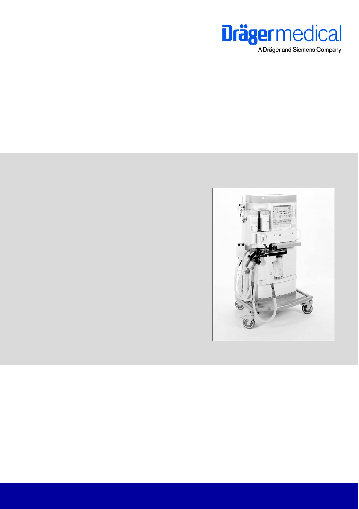
Primus
Anaesthetic Workstation
Revision 6.0
5132.300
9036004
Because you care
Page 2

Page 3

Contents
General
1 Symbols and Definitions 3
2 Notes 3
Function Description
1 General 7
1.1 Medical purpose ..................................................................................................................... 7
1.2 Product classification ............................................................................................................. 8
1.3 Protection classes .................................................................................................................. 8
1.4 Short description of Primus ...................................................................................................9
1.4.1 Ventilator .................................................................................................................. 9
1.4.2 Breathing system ...................................................................................................... 9
1.4.3 Mixer (fresh gas metering) .................................................................................... 10
1.4.4 Monitor control panel .............................................................................................. 11
1.4.5 Options ................................................................................................................... 12
1.5 Primus component structure ............................................................................................... 12
1.5.1 NEUTRAL POINT PCB .......................................................................................... 12
1.5.2 Graphical User Interface (GUI) ............................................................................... 13
1.5.3 Mixer ....................................................................................................................... 13
1.5.4 VGC (Ventilation and Gas Controller) .................................................................... 13
1.5.5 Power pack ............................................................................................................. 13
1.5.6 Cylinder pressure regulator .................................................................................... 13
2 NEUTRAL POINT PCB 15
All rights reserved. Copyright reserved.
K5132300IECIVZ.fm 02.06.06
I
Page 4

Contents
3 GUI 17
3.1 Monitor Control Panel (MoBi) ...............................................................................................17
3.1.1 MONITOR CONTROL PANEL PCB ....................................................................... 19
3.2 S-Box (interface box) ............................................................................................................20
3.2.1 BACKPLANE PCB ..................................................................................................21
3.2.2 SpO2 sampling function (option) .............................................................................22
4 Patient gas module 23
4.1 Version PGM2 ...................................................................................................................... 23
4.1.1 ILCA2 function ........................................................................................................26
4.1.2 PGM2 with Pato O2 sensor ....................................................................................28
4.1.3 PGM2 with Servomex O2 sensor ...........................................................................30
4.1.4 Pneumatics of the PGM2 ........................................................................................32
4.2 Version PGM ........................................................................................................................ 34
4.2.1 PGM pneumatic components ................................................................................. 37
4.3 Operating modes .................................................................................................................. 39
4.3.1 "Reduced Accuracy" mode (PGM only) .................................................................. 39
4.3.2 "ISO" mode (ISO accuracy) (PGM/PGM2) ............................................................. 39
4.3.3 "Full Accuracy" mode (PGM only) ..........................................................................39
4.3.4 "Standby" response of the Primus (PGM/PGM2) ................................................... 39
4.3.5 IRIA/ILCA2 calibration ...........................................................................................39
4.3.6 Auto-Wake-up function ..........................................................................................39
4.3.7 O2 sensor/Servomex ..............................................................................................39
4.4 PGM/PGM2 electronics ........................................................................................................40
4.4.1 MOPS PCB (PGM/PGM2) ......................................................................................40
4.4.2 AMO IRIA PCB (PGM) ............................................................................................40
4.4.3 AMO ILCA2 PCB (PGM2) .......................................................................................40
4.4.4 AMO O2 PUMP PCB (PGM) ..................................................................................40
4.4.5 AMO MFM PCB (PGM2) ........................................................................................40
4.4.6 AMO FLOW ILCA PCB (PGM/PGM2) .................................................................... 41
K5132300IECIVZ.fm 02.06.06
All rights reserved. Copyright reserved.
II
Page 5

Contents
5 Mixer 43
5.1 Operating modes .................................................................................................................. 46
5.1.1 10 VA mode ............................................................................................................ 46
5.1.2 'Normal' mode ........................................................................................................ 46
5.2 Layout ................................................................................................................................... 46
5.2.1 MIXER PCB ............................................................................................................ 46
5.2.2 PRIMUS CPU PCB (mixer) .................................................................................... 47
5.3 Gas inlet block (AIR, O2 and N2O) ...................................................................................... 48
5.3.1 Pneumatic components, gas inlet block ................................................................. 50
5.3.2 Pressure status LEDs ............................................................................................. 52
5.4 Mixer block ........................................................................................................................... 55
5.5 Pneumatic system ................................................................................................................ 56
5.5.1 VMIX valves ........................................................................................................... 57
5.5.2 PDMIX and RM ...................................................................................................... 57
5.5.3 PTANK (pressure sensor) ....................................................................................... 57
5.5.4 VTANK valve .......................................................................................................... 57
5.5.5 VMGS (fresh gas flow valve) .................................................................................. 57
5.5.6 PDMGSHI / PDMGSLO (differential pressure sensors) ......................................... 57
5.5.7 PSYS (pressure sensor) ......................................................................................... 57
5.5.8 VSWAK (A-cone valve) .......................................................................................... 58
5.5.9 VBAK (safety valve) ............................................................................................... 58
5.5.10 TEMPTANK / TEMPBLOCK (temperature sensors) ............................................... 58
5.5.11 VSFC (safety O2 adjuster) ..................................................................................... 58
5.5.12 VO2+ (flush button) ................................................................................................ 58
K5132300IECIVZ.fm 02.06.06
All rights reserved. Copyright reserved.
III
Page 6

Contents
6 VGC 59
6.1 VGC electronics ....................................................................................................................61
6.1.1 VGC POWER PCB .................................................................................................61
6.1.2 PRIMUS ANALOG PCB .........................................................................................61
6.2 Piston cylinder unit (PCU) ....................................................................................................62
6.3 VGC pneumatic block ...........................................................................................................64
6.4 VGC pneumatic system ........................................................................................................65
6.5 Interface plate .......................................................................................................................67
6.6 Breathing system ..................................................................................................................69
6.6.1 Compact breathing system pneumatic components ............................................... 72
6.7 Automatic ventilation ............................................................................................................73
6.7.1 Inspiration ...............................................................................................................73
6.7.2 Expiration ................................................................................................................75
6.8 Manual ventilation .................................................................................................................77
6.8.1 Inspiration ...............................................................................................................77
6.8.2 Expiration ................................................................................................................78
6.9 Spontaneous breathing .........................................................................................................79
6.9.1 Inspiration ...............................................................................................................79
6.9.2 Expiration ................................................................................................................80
7 Ventilation modes with software version 2.n or higher 81
7.1 “Volume Mode” .....................................................................................................................81
7.2 “Pressure Mode” ...................................................................................................................84
7.3 “Pressure Support Mode” .....................................................................................................87
7.4 “Man./Spont Mode” ...............................................................................................................88
7.5 Switching ventilation modes .................................................................................................89
7.6 HLM mode ............................................................................................................................89
IV
K5132300IECIVZ.fm 02.06.06
All rights reserved. Copyright reserved.
Page 7

Contents
8 Power pack 91
8.1 Power pack input .................................................................................................................. 91
8.2 Power switch ........................................................................................................................ 92
8.3 Output voltages and currents ............................................................................................... 92
8.4 Secondary connector ........................................................................................................... 93
8.5 UPS batteries ....................................................................................................................... 93
8.6 Power pack CAN communication ......................................................................................... 94
8.7 Power failure warning ........................................................................................................... 94
9 Operating modes 95
9.1 Cold start .............................................................................................................................. 95
9.2 Standby mode ...................................................................................................................... 95
9.3 Shutdown ............................................................................................................................. 95
9.4 Safety mode ......................................................................................................................... 95
9.4.1 Safety O2 flow ........................................................................................................ 95
9.5 Alarm system ........................................................................................................................ 96
10 Cylinder pressure reducer 97
11 Vaporizer 101
12 Bronchial aspirator 103
12.1 Intended use ....................................................................................................................... 103
12.2 Device types ....................................................................................................................... 103
12.2.1 Variants ................................................................................................................. 103
12.3 Bronchial aspirator with ejector .......................................................................................... 103
12.3.1 Pneumatics (ejector) ............................................................................................ 104
12.4 Bronchial aspirator with vacuum ........................................................................................ 105
12.4.1 Pneumatics (vacuum) ........................................................................................... 106
13 Block diagrams and pneumatic components layout 109
13.1 Introduction ......................................................................................................................... 109
All rights reserved. Copyright reserved.
K5132300IECIVZ.fm 02.06.06
V
Page 8

Contents
Maintenance Procedures
1 Safety precautions 123
2 Rear panel 125
2.1 Rear panel removal ............................................................................................................125
2.2 Rear panel fitting .................................................................................................................125
2.2.1 Rear panel final check ..........................................................................................125
3 Replacing bronchial suction device bacterial filter 127
4 Replacing filter mat on PGM fan 129
5 Replacing bacterial filter and Nafion tube in PGM 131
5.1 Removing the PGM ............................................................................................................131
5.1.1 Removing the PGM housing ................................................................................. 131
5.2 Replacing the bacterial filter ...............................................................................................133
5.3 Replacing the Nafion tube ................................................................................................. 133
5.4 Fitting the PGM housing (new) ...........................................................................................134
6 Cleaning or replacing filter mat in housing cover 137
6.1 Filter mat removal ...............................................................................................................137
6.1.1 Filter mat fitting .....................................................................................................138
7 Replacing filter mat in power pack 139
8 Replacing UPS batteries 141
8.1 Power pack removal ...........................................................................................................141
8.2 Removing UPS batteries ....................................................................................................142
8.3 Fitting UPS batteries ...........................................................................................................144
8.4 Fitting the power pack .........................................................................................................146
VI
K5132300IECIVZ.fm 02.06.06
All rights reserved. Copyright reserved.
Page 9

Contents
9 Cleaning or replacing large and small filter mats in VGC 147
9.1 Removal of large filter mat ................................................................................................. 147
9.1.1 Fitting of large filter mat ........................................................................................ 149
9.2 Removal of small filter mat ................................................................................................. 149
9.2.1 Fitting of small filter mat ....................................................................................... 150
10 Replacing bag upper roller diaphragm 151
11 Replacing the lower rolling seal (VGC) 153
11.1 Removing the VGC ............................................................................................................ 153
11.2 Removing the piston-cylinder unit ...................................................................................... 158
11.2.1 Removing/Fitting the lower rolling seal ................................................................. 162
11.3 Mounting piston-cylinder unit .............................................................................................. 168
12 Replacing pressure regulators PRPN2O, PRPAIR, PRPO2 173
12.1 Removing gas inlet block pressure regulators ................................................................... 173
12.2 Fitting pressure regulators .................................................................................................. 174
13 Replacing CPU PRIMUS PCB lithium battery 179
13.1 Removing mixer ................................................................................................................. 179
13.2 Removing mixer cover ........................................................................................................ 182
13.3 Replacing the lithium battery .............................................................................................. 183
13.4 Fitting mixer cover .............................................................................................................. 184
13.5 Mixer fitting ......................................................................................................................... 184
14 Replacing PEEP diaphragm and MAN/SPONT diaphragm 185
15 Pressure regulator major overhaul 189
15.1 Safety precautions .............................................................................................................. 189
15.2 Required spare parts .......................................................................................................... 190
15.3 Service Equipment Required .............................................................................................. 191
15.4 Removing the pressure regulator ....................................................................................... 192
15.5 Replacing the “Major Overhaul” spare parts set ................................................................. 194
All rights reserved. Copyright reserved.
K5132300IECIVZ.fm 02.06.06
VII
Page 10

Contents
Schematics and Diagrams
1 Primus pneumatic components diagram 203
2 Schematics and Diagrams 209
Annex
Parts catalog
Test List
Technical Information
VIII
K5132300IECIVZ.fm 02.06.06
All rights reserved. Copyright reserved.
Page 11

General
1
Page 12

2
Page 13

Primus General
1 Symbols and Defini-
tions
WARNING
A WARNING statement provides important information about a potentially hazardous situation which, if not avoided, could result in death
or serious injury.
CAUTION
A CAUTION statement provides important information about a potentially
hazardous situation which, if not avoided, may result in minor or moderate
injury to the user or patient or in damage to the equipment or other property.
NOTE
A NOTE provides additional information intended to avoid inconvenience
during operation.
Definitions according to German standard DIN 31051:
Inspection = examination of actual condition
Maintenance = measures to maintain specified condition
Repair = measures to restore specified condition
Servicing = inspection, maintenance, and repair
2Notes
This Technical Documentation conforms to the IEC 60601-1 standard.
Read each step in every procedure thoroughly before beginning any test.
Always use the proper tools and specified test equipment. If you deviate from
the instructions and/or recommendations in this Technical Documentation,
the equipment may operate improperly or unsafely, or the equipment could
be damaged.
It is our recommendation to use only Dräger parts and supplies.
The maintenance procedures described in this Technical Documentation may
be performed by qualified service personnel only. These maintenance procedures do not replace inspections and servicing by the manufacturer.
The information in this Technical Documentation is confidential and may not
be disclosed to third parties without the prior written consent of the manufacturer.
This Technical Documentation is for the purpose of information only. Product
descriptions found in this Technical Documentation are in no way a substitute
for reading and studying the Instructions for Use/Operating Manual enclosed
with the product at the time of delivery.
All rights reserved. Copyright reserved.
Version 3.0_ Released_Printed on_02.06.06_General_Technical_Documentation.fm
5132.300
3
Page 14

General Primus
Know-how contained in this Technical Documentation is subject to ongoing
change through research and development and Dräger Medical reserves the
right to make changes to this Technical Documentation without notice.
NOTE
Unless otherwise stated, reference is made to laws, regulations or standards (as amended) applicable in the Federal Republic of Germany for
equipment used or serviced in Germany. Users or technicians in all other
countries must verify compliance with local laws or applicable international
standards.
Version 3.0_ Released_Printed on_02.06.06_General_Technical_Documentation.fm
All rights reserved. Copyright reserved.
4
5132.300
Page 15

Function Description
5
Page 16

6
Page 17

Primus Function Description
1 General
1.1 Medical purpose
Primus is an anaesthetic workstation for automatic and manual ventilation
and spontaneous breathing, usable for adults, children and infants.
Application:
– Inhalation anesthesia in rebreathing systems.
– Inhalation anesthesia in virtually closed systems for low-flow and mini-
mum-flow applications.
– Inhalation anesthesia in non-rebreathing systems with separate fresh gas
output for connection of “Bain” or “Magill” system, for example, with a
fresh gas flow of 0.2 L/min to 18 L/min.
Changed ventilation modes (software 2.n or higher):
– Volume-controlled ventilation “Vol u m e Mode”. Switchable functions:
• Synchronization.
• Pressure support (optional).
– Pressure-controlled ventilation “Pressure Mode” Switchable functions:
• Synchronization.
• Pressure support (optional).
– Manual ventilation “MAN”.
– Spontaneous breathing “SPONT”.
– Pressure-assisted ventilation “Pressure Support” (optional).
Ventilation modes (up to software d1.06):
– Volume-controlled ventilation “IPPV, SIMV”.
– Pressure-controlled ventilation “PCV”
– Manual ventilation “MAN”.
– Spontaneous breathing “SPONT”.
Displayed values:
– Peak pressure “Ppeak”, mean pressure “Pmean”, plateau pressure
“Pplat, PEEP”.
– Expiratory minute volume “MV”, tidal volume “VT”, respiratory frequency
“f”.
– Inspiratory and expiratory concentrations of O2, N2O, anesthetic gas and
CO2.
– System compliance and leakage minute volume.
– Functional oxygen saturation “SpO2” and pulse rate (optional).
All rights reserved. Copyright reserved.
Version 2.0_ Released_Printed on_02.06.06_F5132300T01_Allgemeines.fm
5132.300
7
Page 18

Function Description Primus
Curve diagrams:
– Airway pressure “Paw”.
– Inspiratory and expiratory flow “V”.
– Inspiratory and expiratory concentrations of O2, CO2 and anesthetic gas.
– Plethysmogram (optional).
– P/V loops and flow/V loops (optional in software 2.n or higher).
Bargraph:
– Display of inspiratory tidal volume, expiratory tidal volume and leakage
tidal volume.
– Volumeter.
– Econometer (optional in software 2.n or higher).
Time trends of measured values (trends) are additionally available.
Monitoring:
– By programmable alarm limits which can be adjusted automatically to the
respective ventilation situation.
Monitored parameters:
– Airway pressure “Paw”.
– Expiratory minute volume “AMV”.
– Apnea (deactivated in heart-lung machine mode (HLM mode)).
– Inspiratory and expiratory anesthetic gas concentrations.
– Detection of anesthetic gas mixtures.
– Inspiratory O2 and N2O concentrations (breathing-phase independent
measurement in HLM mode).
– Inspiratory and expiratory CO2 concentrations (breathing-phase indepen-
dent measurement in HLM mode).
– Optional: Oxygen saturation (alarms deactivated in HLM mode), pulse
rate.
1.2 Product classification
– Class II b, according to rules 2, 9 and 11 of the Medical Products Direc-
tive.
1.3 Protection classes – Protection class I, type B according to EN 60601-1.
– With optional SpO2: Protection class I, type BF.
Version 2.0_ Released_Printed on_02.06.06_F5132300T01_Allgemeines.fm
All rights reserved. Copyright reserved.
8
5132.300
Page 19

Primus Function Description
1.4 Short description of
Primus
1.4.1 Ventilator
The following sections provide an overview of the Primus components.
Figure 1 Ventilator with breathing system
The electronically controlled and driven ventilator has the following features:
– Tidal volumes of 20 mL (10 mL with software 2.n or higher) to 1400 mL at
frequencies of 3/min to 80/min.
– Peak flow of up to 150 L/min.
– Ventilation modes such as IPPV, PCB, SIMV (plus adjustable trigger, plus
adjustable PEEP) and MAN/SPONT (up to software 1.n).
– Ventilation modes such as volume mode, pressure mode, pressure sup-
port (optional) and MAN/SPONT with switchable synchronization and
pressure assistance (optional).
1.4.2 Breathing system The breathing system comprises the following components:
– Integrated absorber, either reusable or disposable.
– Electronic interfaces for inspiratory and expiratory flow measurement.
– Direct patient section heating is integrated into the valve plate of the
breathing system.
– Pneumatic interface to ventilator.
– Fresh gas isolation and minimized compliance.
All rights reserved. Copyright reserved.
Version 2.0_ Released_Printed on_02.06.06_F5132300T01_Allgemeines.fm
5132.300
9
Page 20
Function Description Primus
1.4.3 Mixer (fresh gas metering)
The electronic mixer offers the following features:
– Gas metering for O2, N2O and AIR.
– Metering range from 200 mL/min to 18 L/min.
– Alarm monitoring for the pressure values of the central supply (CS) and
the cylinder supply. LEDs on the front panel indicate the pressure status.
– ORC function for low-flow and minimum-flow applications.
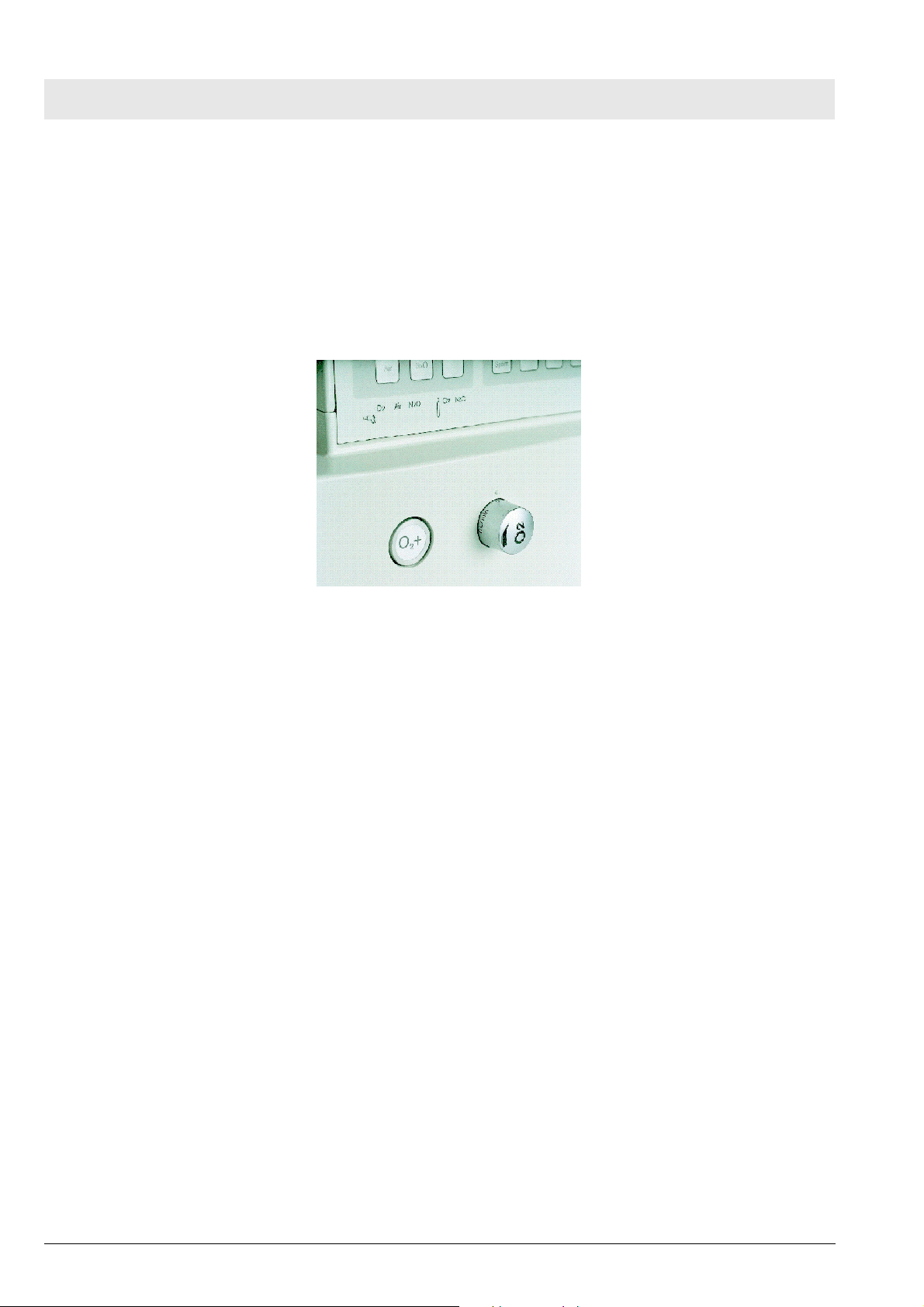
– O2 flush and mechanical safety O2 adjuster (see Figure 2).
Figure 2 O2 flush (O2+), mechanical safety O2 adjuster
– Double Vapor plug-in system with interlock.
– Optional external A-cone as fresh gas outlet.
10
5132.300
Version 2.0_ Released_Printed on_02.06.06_F5132300T01_Allgemeines.fm
All rights reserved. Copyright reserved.
Page 21

Primus Function Description
1.4.4 Monitor control panel
Figure 3 Monitor control panel
The parameters for fresh-gas flow control, ventilation, and gas monitoring are
displayed on a 12-inch color screen.
The following parameters are monitored:
– Airway pressure.
– Inspiratory and expiratory flow.
– Circle system leakage.
– Inspiratory and expiratory O2 concentration.
– CO2 measurement and anesthetic gas measurement.
– Anesthetic gas detection.
– Quantitative measurement of mixed-gas values and MAC calculation
(age-relevant).
A data view, a trend view (graphical) and a log view can be selected.
As from software release 2.n the following settings are possible:
– Free configuration of 3 real-time curves and different numerical values.
– Body-weight-relevant ventilator presettings (Vt and frequency) and age-
relevant calculation of minimum alveolar concentration (MAC ) according
to “Mapleson” as well as age-relevant scaling of volumeter and influence
on ventilation monitoring.
All rights reserved. Copyright reserved.
Version 2.0_ Released_Printed on_02.06.06_F5132300T01_Allgemeines.fm
5132.300
11
Page 22
Function Description Primus
The safety concept incorporates the following tests:
– Automatic self-test with mixer test, ventilator test and test of the breathing
system.
– Test and automatic calibration of all sensors.
1.4.5 Options Primus is prepared for future upgrading with the following options:
– Integrated SpO2 measurement.
– Consumption-free O2 measurement (with software 2.n or higher).
– PAW preview – display of expected airway pressure curve when chang-
ing parameters.
– P/V and flow/V loops (with software 2.n or higher).
– Econometer function (with software 2.n or higher).
– Additional ventilation modes (e.g. autoflow, CPAP).
– Additional languages available for display texts.
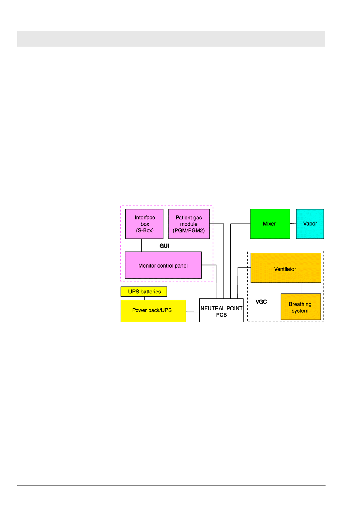
1.5 Primus component
structure
Figure 4 Primus component structure
In the “Block diagrams” section, you will find a detailed block diagram of the
Primus.
1.5.1 NEUTRAL POINT PCB The NEUTRAL POINT PCB connects the components of the Primus to the
power supply, additional signal wires and the CAN bus.
More details are given in the following section on the NEUTRAL POINT PCB.
12
5132.300
Version 2.0_ Released_Printed on_02.06.06_F5132300T01_Allgemeines.fm
All rights reserved. Copyright reserved.
Page 23

Primus Function Description
1.5.2 Graphical User Interface
(GUI)
The GUI has the following components:
– On the Monitor Control Panel (MoBi) the ventilation mode is displayed.
Limit and target values are specified and the ventilation and anesthesia
parameters are displayed.
– S-Box (Interface box). PC interfaces and optional measuring functions
such as SpO2 and BIS
TM
.
– Patient Gas Module (PGM) for measurement of O2, CO2 and anesthetic
gas.
For more details refer to the section headed GUI.
1.5.3 Mixer The mixer comprises the following function units:
– Electronically controlled and monitored mixer.
– Vapor plug-in system for one or two conventional vaporizer types.
– External fresh gas outlet, A-cone (optional).
– Pressure monitoring for CS and compressed gas cylinders.
More details are given in the following section on the mixer.
1.5.4 VGC (Ventilation and
Gas Controller)
The VGC comprises the following function units:
– Electronically controlled and driven ventilator.
– Integrated breathing system for “low flow” and “minimum flow” applica-
tions.
For more details refer to the section headed VGC.
1.5.5 Power pack The power pack comprises:
– Switched-mode power supply unit.
– Uninterruptible power supply (UPS) with one battery pack consisting of
two 12 V lead-gel batteries.
– Battery charging management.
For more details refer to the section headed Power pack.
1.5.6 Cylinder pressure regulator
The cylinder pressure regulators reduce the pressure of the optional compressed gas cylinders.
For more details refer to the section headed Cylinder pressure regulators.
The function description relating to the NEUTRAL POINT PCB follows.
All rights reserved. Copyright reserved.
Version 2.0_ Released_Printed on_02.06.06_F5132300T01_Allgemeines.fm
5132.300
13
Page 24

Function Description Primus
14
5132.300
Version 2.0_ Released_Printed on_02.06.06_F5132300T01_Allgemeines.fm
All rights reserved. Copyright reserved.
Page 25

Primus Function Description
2 NEUTRAL POINT
PCB
The NEUTRAL POINT PCB is the central signal and voltage distributor.
Figure 5 Location of the Neutral Point PCB
All rights reserved. Copyright reserved.
Version 2.0_ Released_Printed on_02.06.06_F5132300T02_LP_Sternpunkt.fm
5132.300
15
Page 26

Function Description Primus
Figure 6 Component mounting diagram, NEUTRAL POINT PCB, for leg-
end see Table 1
Table 1 Legend to Figure 6
Item Connector
1 Monitor Control Panel (MoBi).
2 Monitor Control Panel (MoBi).
3 Ventilation and Gas Controller (VGC).
4Mixer B.
5Mixer A.
6 Safety O2 flow valve (microswitch).
7 Power switch (main switch).
8 Halogen lamp
9 Jack plug (production tests).
10 PGM.
11 Power pack A.
12 Power pack B.
13 Not assigned.
The function description relating to the GUI follows.
16
5132.300
Version 2.0_ Released_Printed on_02.06.06_F5132300T02_LP_Sternpunkt.fm
All rights reserved. Copyright reserved.
Page 27
Primus Function Description
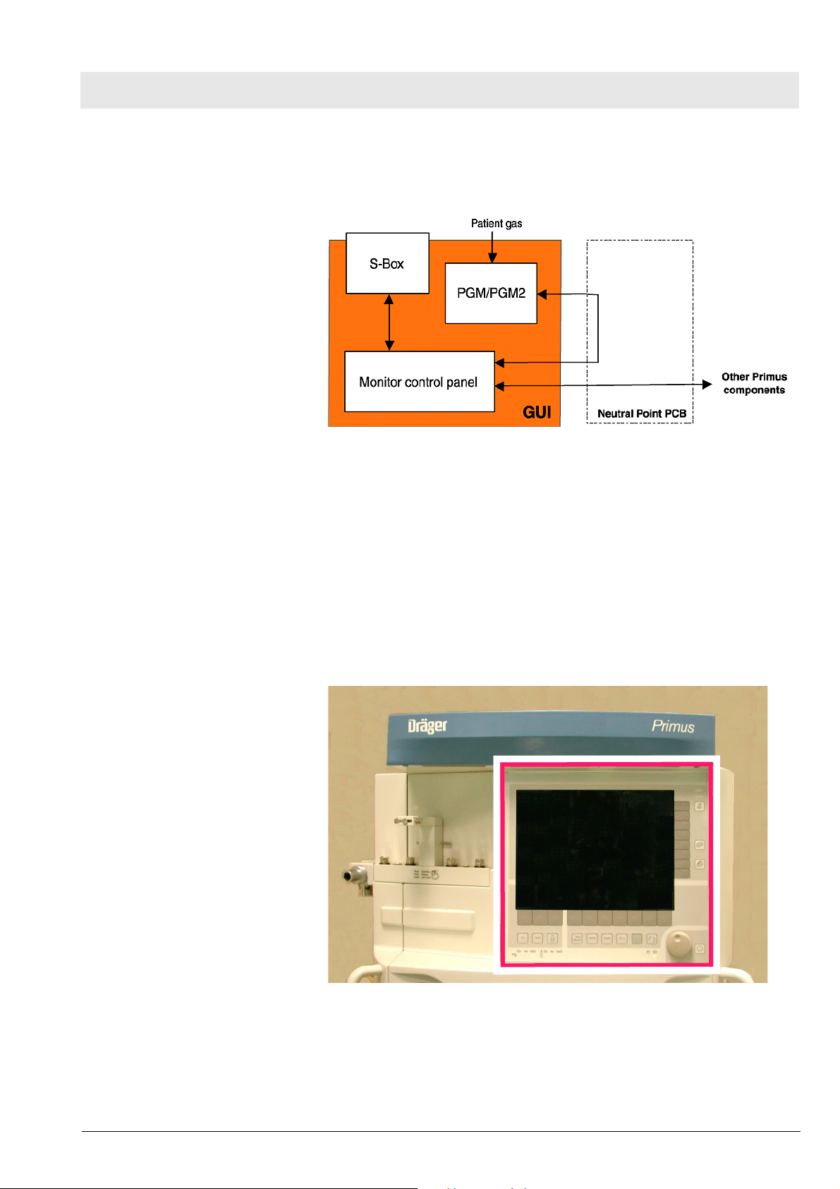
3GUI The following section describes the user interface (“GUI = Graphical User
Interface”).
Figure 7 GUI block diagram
3.1 Monitor Control
Panel (MoBi)
In the “Block diagrams” section, in the block diagram of the Primus, you will
find a block diagram of the GUI.
The GUI has the following components:
– MoBi (monitor control panel).
– S-Box (Interface Box).
– Patient Gas Module (PGM). The function description relating to the
Patienten Gas Module (PGM) follows.
Version 5.0_ Released_Printed on_02.06.06_F5132300T03_GUI.fm
All rights reserved. Copyright reserved.
5132.300
Figure 8 Position of Monitor Control Panel (MoBi)
In the “Block diagrams” section, you will find a block diagram of the MoBi.
17
Page 28
Function Description Primus
The user and Primus communicate via the MoBi. The MoBi display presents
system and patient information. It is here that the user sets the parameters
and ventilation modes.
The Patient Gas Module (PGM) is connected to the GUI.
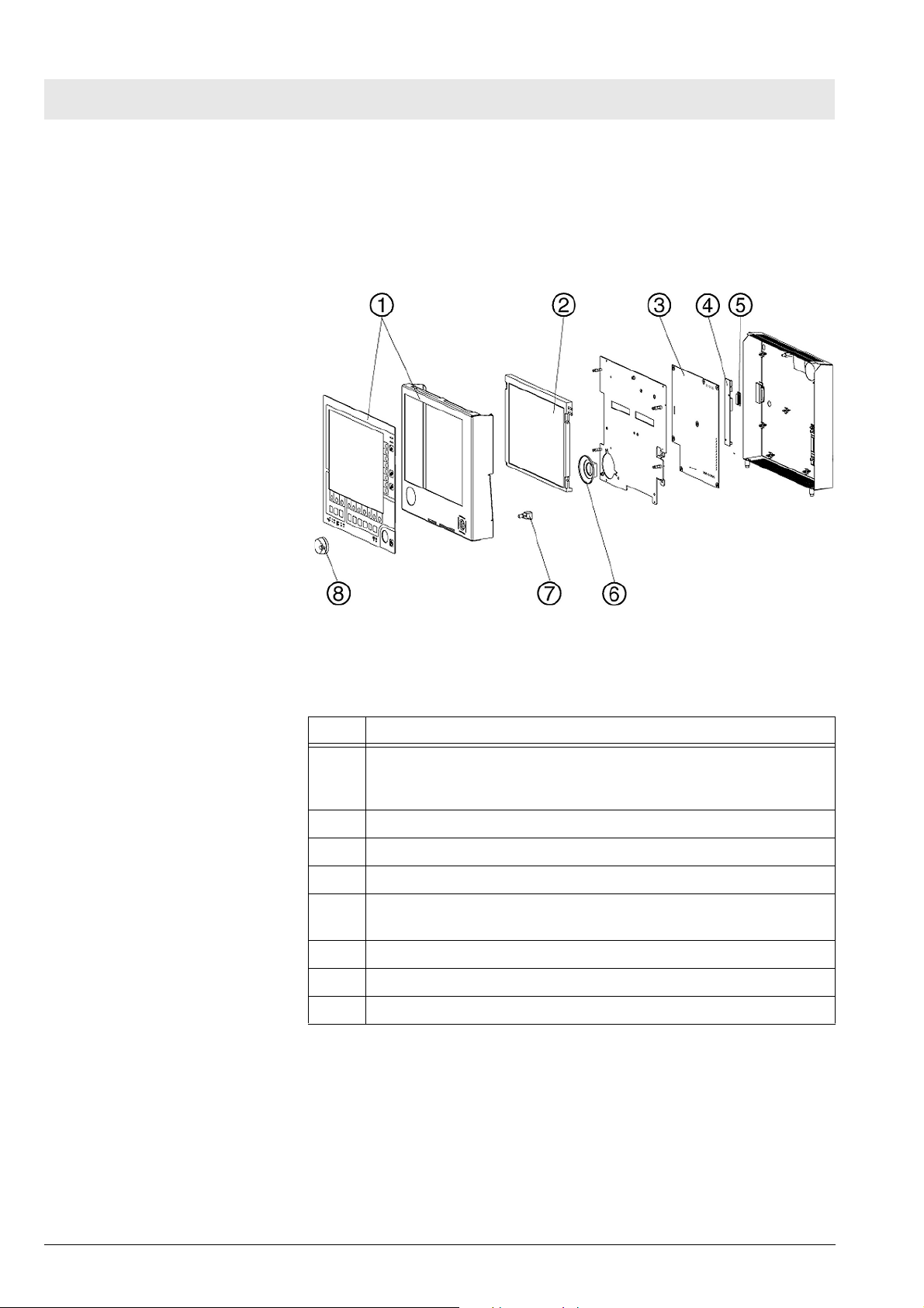
Figure 9 Exploded view of MoBi, for legend see Ta b le 2
Table 2 Legend to Figure 9
Item Components
1 Front panel with membrane keypad. Includes keypad membrane
covering with design imprint, keys, LEDs (e.g. for CS gases), the
carrier plate and the shielding, anti-glare glass screen.
2 12 inch color display (TFT, resolution: 800 x 600).
3 MONITOR CONTROL PANEL PCB (motherboard).
4 Backlight converter (display backlighting).
5 LCD800 PCB (adapter PCB for connection of different makes of
display).
6 Loudspeaker.
7 Rotary transducer.
8 Control knob (central operator control element).
18
5132.300
Version 5.0_ Released_Printed on_02.06.06_F5132300T03_GUI.fm
All rights reserved. Copyright reserved.
Page 29

Primus Function Description
3.1.1 MONITOR CONTROL
PANEL PCB
The following software is installed on the PCB:
– GUI software.
– Monitoring and evaluation software for the PGM.
– Software for Medibus connections and SpO2.
A 2-processor system is in operation on the PCB. It comprises a Display
Master (DiMa) and a Communication Master (CoMa).
The powerful DiMa processor incorporates the following components:
– Motorola processor (MPC823) with 48 MHz clock frequency and 32-bit
address and data buses.
– Flash-PROM (program memory).
– RAM (data memory).
– CAN controller.
– RS232 interface for in-house development purposes.
– Serial communication channel for Ethernet.
The LCD controller is a programmable logic device (“PLD”). A “DRAM” serves
as the video memory.
The CoMa processor system primarily controls communication with the
other Primus components.
The CoMa incorporates the following components:
– Motorola processor (M68332) with 16.7 MHz clock frequency, internal 32-
bit bus and external 16-bit data bus.
– Flash-PROM (program memory).
– RAM (data memory).
– RS232 interface for communication with the SPO2, PGM and Medibus 1 -
3 modules.
– Real-time clock (RTC).
– Keyboard and rotary knob scan, LED actuation and sound output.
– CAN interface.
Both processor systems communicate by way of a Dual-Port RAM (DPR).
This memory device is battery-buffered. The buffering is provided primarily by
the UPS batteries of the Primus. If they fail, the lithium battery on the MONITOR CONTROL PANEL PCB ensures data is retained.
The operating voltage is provided by an unstabilized voltage of 20 V to 30 V
(Vcc). DC converters on the MONITOR CONTROL PANEL PCB generate all
other voltages on the PCB.
The MoBi is interconnected over the CAN bus with the other components of
the Primus (power pack, mixer and VGC).
Version 5.0_ Released_Printed on_02.06.06_F5132300T03_GUI.fm
All rights reserved. Copyright reserved.
5132.300
19
Page 30

Function Description Primus
3.2 S-Box (interface
box)
Figure 10 Position of S-Box
In the “Block diagrams” section, you will find a block diagram of the S-Box.
20
Figure 11 Layout of the S-Box, for legend see Tab l e 3
5132.300
Version 5.0_ Released_Printed on_02.06.06_F5132300T03_GUI.fm
All rights reserved. Copyright reserved.
Page 31

Primus Function Description
Table 3 Legend to Figure 11
Item Components
1 Drawer unit components fully mounted.
2 BACKPLANE PCB.
3 SpO2 ADAPTER PCB (SpO2 PCB not shown).
Figure 12 S-Box, block diagram
The S-Box as standard includes the BACKPLANE PCB and thus the externally available Medibus ports (COM 1-3), IV-System (Ethernet for TIVA) and
a CAN port (SABUS exclusively for debug purposes).
The S-Box is prepared for the SpO2 option.
3.2.1 BACKPLANE PCB The BACKPLANE PCB is the base component for additional modules and
the insulated interfaces to external devices.
In the “Block diagrams” section, you will find a block diagram of the BACK-
PLANE PCB
The BACKPLANE PCB has the following functions:
– Electrical isolation and level conversion of the 3 Medibus ports (RS232).
– Connects the MoBi with the CAN (SABUS) and Ethernet (TCP/IP) con-
nectors.
– Connects the optional hardware (SPO2, IV-System) with the MoBi (as
from SW 1.n).
Version 5.0_ Released_Printed on_02.06.06_F5132300T03_GUI.fm
All rights reserved. Copyright reserved.
5132.300
21
Page 32

Function Description Primus
3.2.2 SpO2 sampling function
(option)
The SpO2 sampling function has the following tasks:
– Non-invasive measurement of functional oxygen saturation in the arterial
blood. The upper and lower alarm limits are monitored on the MONITOR
CONTROL PANEL PCB by the CoMa processor.
– Measurement of pulse rate.
– Monitoring of the pulse rate with upper and lower alarm limits.
The SpO2 sensor essentially comprises two LEDs (light-emitting diodes)
which alternatingly emit infrared light with typical wavelengths of 920 nm and
660 nm respectively. An opposing photodetector measures the radiant intensity. The sensor is placed on a part of the body on which arterial blood vessels can be X-rayed, such as the fingers, toes or bridge of the nose.
The new SpO2 sensor “DS-100A” incorporates a memory chip. The Nellcor
module used in the Primus now detects only this SpO2 sensor. The new sensor is identifiable by the fact that all nine pins are present on the connector.
The SpO2 sensor is connected without a pre-amplifier to the module. The
module communicates through a serial port with the MONITOR CONTROL
PANEL PCB. On the BACKPLANE PCB the module is electrically isolated
with 1.5 kV.
The function description relating to the Patienten Gas Module (PGM) follows.
22
5132.300
Version 5.0_ Released_Printed on_02.06.06_F5132300T03_GUI.fm
All rights reserved. Copyright reserved.
Page 33

Primus Function Description
4 Patient gas module The PGM (patient gas module) or PGM2 is an integral part of the GUI func-
tional unit (see function description GUI.
There are two versions of the patient gas module:
–PGM.
–PGM2.
In the “Block diagrams” section, you will find the block diagrams of the
PGM/PGM2 electronics
Differences between PGM2 and PGM:
PGM PGM2
Anesthetic gas measurement.
O2 sampling. Electrochemical O2 cell. Servomex sensor or
O2 measurement
electronics.
Pump flow. 150 mL 200 mL
Flush flow. 200 mL 250 mL
IRIA. ILCA2.
Pato sensor.
AMO O2 PUMP PCB AMO MFM PCB.
4.1 Version PGM2 The following illustration shows the location of the PGM2 (rear panel of unit is
open).
Version 5.0_ Released_Printed on_02.06.06_F5132300T03_PGM.fm
All rights reserved. Copyright reserved.
5132.300
Figure 13 Location of the PGM2
23
Page 34

Function Description Primus
Figure 14 Exploded view of PGM2, for legend see Tabl e 4
Table 4 Legend to Figure 22
Item Component
1 ILCA2 sensor head.
2 Solenoid valve V1.
3 Pump (200 mL).
4 Insulating foil.
5 MOPS PCB (central processor).
6 PCBs mounting frame.
7 AMO ILCA2 PCB (anesthetic gas analysis).
8 AMO Flow ILCA PCB (flow measurement, pump control, and valve
control).
9 AMO MFM PCB (O2 analysis).
10 “Servomex” O2 sensor or “Pato” O2 sensor.
11 Filter mat.
Version 5.0_ Released_Printed on_02.06.06_F5132300T03_PGM.fm
All rights reserved. Copyright reserved.
24
5132.300
Page 35

Primus Function Description
Item Component
12 Bacterial filter.
13 Holder for WaterLock (water trap).
14 WaterLock.
15 Fan.
16 Solenoid valve V2.
17 Adapter board (connection board).
The PGM2 automatically detects and measures the anesthetic gas in use Halothane, Enflurane, Isoflurane, Desflurane or Sevoflurane. It also detects
and measures mixtures of two of the above anesthetic gases. If it encounters
a mixture of more than two anesthestic gases, the warning “AGas mixture” is
delivered.
CO2, O2 and the anesthetic gas mixture are presented as a real-time curve.
Some of the parameters measured by the PGM2 (etCO2, inCO2 etN2O,
inN2O, etO2 and inO2) are presented on the GUI as digital values.
One component of the PGM2 is the water trap. The water trap is accessible
from the front panel. For position see following diagram.
Version 5.0_ Released_Printed on_02.06.06_F5132300T03_PGM.fm
All rights reserved. Copyright reserved.
5132.300
Figure 15 Position of water trap
25
Page 36

Function Description Primus
4.1.1 ILCA2 function ILCA2 is a gas measuring module for the analgesic N2O, the anesthetic
gases Halothane, Enflurane, Isoflurane, Desflurane and Sevoflurane, and for
measurement of mixtures. ILCA2 conforms to the measurement accuracy
specified by ISO standards.
The ILCA2 module is capable of automatically detecting the above mentioned
gases.
ILCA2 module design
The ILCA2 module principally comprises the following components:
– Sensor head with double-optics, pressure sensor, and electronics.
– Diaphragm pump.
– Pneumatic low pass.
– Solenoid valve for zero calibration.
– Module rack with 3 PCBs.
In the “Block diagrams” section, you will find a block diagram of the ILCA2
module.
Sensor head
The sensor head houses 2 PCBs with the following functions:
– Pre-amplifier PCB for the two multi-channel detectors.
– Base PCB with emitter activation, temperature regulation, absolute pres-
sure measurement and a serial EEPROM holding the serial number, setting and calibration data for operation of the sensor head.
The module rack of the ILCA2 module contains 4 additional PCBs with the
following functions:
– AMO FLOW ILCA PCB - Control of the diaphragm pump and the zero
calibration solenoid. A serial EEPROM stores the necessary data such as
the serial number, hardware/software revision, control parameters etc.
– AMO ILCA2 PCB - Here the necessary supply voltages are generated
and the data transfer from the ILCA2 sensor to the MOPS PCB is implemented.
– AMO MFM PCB - This circuit board amplifies the signal from the Ser-
vomex sensor.
– MOPS PCB - Primarily delivers the data for further processing via an RS
232 interface.
Measurement principle
26
The measurement principle of the ILCA2 module is based on the absorption
of infrared light by the various media (see Figure 16). The sensor head consists of a double measuring head with one emitter each which emits a broad
spectrum of infrared light. The light beam passes through a cuvette, through
which the gas being measured is also drawn by means of a diaphragm pump.
Downstream of the cuvette the light beam hits a multi-channel detector with
IR filters. The filters are dimensioned so that only the light in the absorption
wavelength of the measured gases is transmitted. If a gas is present light is
absorbed. The higher the partial pressure of the gas, the greater the absorption of the light and the smaller the sensor signal.
5132.300
Version 5.0_ Released_Printed on_02.06.06_F5132300T03_PGM.fm
All rights reserved. Copyright reserved.
Page 37

Primus Function Description
Figure 16 Principle of multi-channel detector with IR filters
Table 5 Legend to Figure 16
Item Meaning
1 Infrared light.
2 Beam splitter.
3 Sensor chip.
4 Infrared filter.
5 Sensor window.
Version 5.0_ Released_Printed on_02.06.06_F5132300T03_PGM.fm
All rights reserved. Copyright reserved.
5132.300
27
Page 38

Function Description Primus
4.1.2 PGM2 with Pato
O2 sensor
The oxygen analyser measures the patient's O2 concentration at the Y-piece.
Measurement principle
The oxygen sensor uses the effect that oxygen molecules are attracted very
much more strongly to a magnetic field (paramagnetism) than the molecules
of other gases, which in some cases are repelled by the magnetic field (diamagnetism).
Layout
The Pato houses a cuvette containing a sensor system, the cuvette is located
between two electromagnets.
Figure 17 Pato system structure
Table 6 Legend to Figure 17
Item Component
1 Magnetic system
2 Sensor system
3 Cuvette
4 Magnetic system
This sensor system comprises the gas path (cuvette) and the sensor inside
the measurement compartment.
The measurement compartment is designed as a bulge in the gas path.
The sensor consists of a heating element and thermoelement assembly.
Version 5.0_ Released_Printed on_02.06.06_F5132300T03_PGM.fm
All rights reserved. Copyright reserved.
28
5132.300
Page 39

Primus Function Description
Figure 18 Pato sensor system
Table 7 Legend to Figure 18
Item Name
1 Measurement compartment
2 Heating element and thermoelement assembly
3 Gas path
4 Sensor element
Function
The electromagnets generate an alternating field.
The sampling gas flows through the cuvette and the gas path in the sensor
system.
The heating element heats up the sampling gas to operating temperature, the
thermoelement measures the temperature.
The outer alternating magnetic field influences the mobility of the oxygen contained in the sampling gas.
The changing mobility alters the heat transfer in the sampling gas which
results in the thermoelement measuring a changing temperature.
Version 5.0_ Released_Printed on_02.06.06_F5132300T03_PGM.fm
All rights reserved. Copyright reserved.
5132.300
The exent of the heat transfer variation depends on the oxygen concentration
in the sampling gas.
The ILCA2 module converts the temperature change in an oxygen concentration value which is then displayed on the connected patient monitor.
29
Page 40

Function Description Primus
4.1.3 PGM2 with Servomex
O2 sensor
The Servomex sensor uses the fact that oxygen molecules have a stronger
paramagnetic characteristic (attracted to a magnetic field) than the molecules
of other gases that are sometimes even diamagnetic (repulsed by a magnetic
field).
The following position numbers refer to Figure 19.
The permanent magnets (7 and 12) in the sensor create a symmetric magnet
field (11). The magnet field contains two nitrogen-filled quartz spheres (9)
arranged in the form of dumbbells. The dumbbell is suspended rotating from
a taut platinum band. A reel of platinum wire is wound around the dumbbell
as a feedback coil (10).
When oxygen flows through the measuring cell (1 and 6), the magnetic field
(11) changes based on the paramagnetic effect of the oxygen dependent on
its concentration. This rotates the quartz spheres (9) of the dumbbells out of
the magnetic field.
A mirror attached to the pivot of the dumbbell (8) reflects a light beam (5) onto
a photocell pair (4). The photocells are connected to an amplifier (3) of which
the output signal supplies the feedback coil (10) of the dumbbell. The dumbbell is rotated back by the current in the feedback coil (10) until the light beam
(5) is illuminating both photocells (4) equally by means of the mirror (8). Then
the system is at equilibrium. The current flowing through the feedback coil
(10) is proportional to the paramagnetism of the oxygen and thus a measure
of the oxgen concentration, which is displayed on the display instrument (2).
30
5132.300
Version 5.0_ Released_Printed on_02.06.06_F5132300T03_PGM.fm
All rights reserved. Copyright reserved.
Page 41

Primus Function Description
Version 5.0_ Released_Printed on_02.06.06_F5132300T03_PGM.fm
All rights reserved. Copyright reserved.
5132.300
Figure 19 Schematic representation of the Servomex sensor
31
Page 42

Function Description Primus
4.1.4 Pneumatics of the PGM2 In the “Block diagrams” section, you will find a schematic of the PGM2 pneu-
matic components.
Figure 20 Schematic of PGM2 pneumatic components, see legend Ta bl e
10
Table 8 Legend to Figure 24
Item Meaning
1 Sampling gas.
2 Goretex membrane (flow 20 mL).
3 Goretex membrane (flow 180 mL).
4 Water trap.
5 Teflon tube.
6 Nafion tube.
7 ILCA2 solenoid valve (pneutronics).
8 Room air (calibration).
9 Filter.
10 ILCA2 (anesthetic gas analysis).
11 O2 sensor.
12 Solenoid valve (pneutronics).
13 Filter.
14 OLC pump 200 mL (DC diaphragm pump).
32
15 Gas outlet.
C1 Volume.
R1 Restrictor.
R2
P Differential pressure sensor.
The item numbers and abbreviations occurring in this section relate to Figure
24.
5132.300
Version 5.0_ Released_Printed on_02.06.06_F5132300T03_PGM.fm
All rights reserved. Copyright reserved.
Page 43

Primus Function Description
The sample gas (1) enters the water trap (4). In the water trap are two Goretex membranes (1, 2). The moisture in the sample gas cannot pass through
the Goretex membranes. This prevents water from reaching the ILCA2 (flow
approx. 180 mL/min). Consequently no water can penetrate the bypass
branch (flow approx. 20 mL/min) either. An approximately 10 cm long Teflon
tube (5) serves as a resistor, and meters the flow in the bypass branch.
If the water in the water tank reaches to the level of the membranes, they are
closed off by the water. An error message is displayed on-screen. A filling
level detector is therefore no longer necessary.
The sample gas flows through the Nafion tube (6) and is additionally dried.
The sample gas then passes on to the ILCA2 solenoid valve (7). Depending
on the valve switching state, either the sample gas (1) or, during calibration,
the room air (8) reaches the ILCA2. The sample gas is fed through the
cuvette (10) of the ILCA2 and passes on to the “Servomex” O2 sensor (11).
When the Primus is in leak test mode, and the PGM2 in standby, the pump
(14) is shut off. Whenever the pump is off, the solenoid valve (12) interrupts
the gas flow to the system. This does not increase the leakage value.
The following low-pass filter comprises the restrictor (R1) and the
volume (C1).
R1 is dimensioned as follows:
– R1 is small enough for the pump not to be placed under unnecessary
strain.
– R1 is large enough so that the pump pressure surges occurring in the
ILCA2 cuvette do not impair the signal ratio and noise ratio in gas sampling.
– The pressure drop at R1 is measured. The measured value is used for
pump control.
The pneumatic low-pass components are integrated into the module housing
of the electronics. The low-pass minimizes the pressure surges generated by
the pump. Downstream of the pneumatic low-pass filter the sample gas
passes to the pump.
The flow through the pump (14) in measuring mode is approx. 200 mL/min
(flush flow approx. 250 mL/min). The supply voltage of the pump is in the
range from 2.5 VDC to 7.5 VDC at a current of up to 150 mA.
Dimensioning of R2:
In a calibration, the switching of the ILCA2 solenoid valve (7) is tested with
the pressure sensor (in the sensor head). In this case the pressure drop via
R2 and the filter (9) must be significantly less than the minimum pressure
drop through the water trap and the sample gas tube. In the event of an error,
an error log entry is generated.
Version 5.0_ Released_Printed on_02.06.06_F5132300T03_PGM.fm
All rights reserved. Copyright reserved.
5132.300
In substitution for a flowmeter, the pressure is measured with a differential
pressure sensor (P) upstream and downstream of the low pass.
The AMO FLOW ILCA PCB controls the pump with the pressure signal as the
input variable.
33
Page 44

Function Description Primus
In order to ensure an adequate measurement accuracy, an automatic zero
calibration is performed periodically. For this, room air is drawn in by the diaphragm pump through the ILCA2 solenoid (zero calibration valve) and
passed through the sensors. The zero calibration valve is controlled by the
AMO Flow ILCA PCB.
Further measures to safeguard measurement accuracy:
– Heating of the cuvette so the intensity of the light beam is not affected by
condensation. As the temperature also influences the measurement
result, the cuvette temperature is kept constant by means of a control
loop.
– The pressure in the cuvette likewise influences the result. So the pres-
sure is measured and entered as a correction variable into the system.
4.2 Version PGM The following diagram shows the position of the PGM with the rear panel
open.
34
Figure 21 Position of the Patient Gas Module (PGM)
5132.300
Version 5.0_ Released_Printed on_02.06.06_F5132300T03_PGM.fm
All rights reserved. Copyright reserved.
Page 45

Primus Function Description
Figure 22 Exploded view of the PGM, legend Table 9
Table 9 Legend to Figure 22
Item Components
1 Connection board.
2 IRIA cuvette.
3 IRIA = “Infrared Rapidly Identifying Analyzer”. Sensor head of
anesthetic gas analyzer.
4 Bacterial filter.
5 Fan.
6 Water trap.
7 Filter mat.
8 O2 cell (fast O2 analysis).
9 MOPS PCB (electronics).
10 AMO IRIA PCB (anesthetic gas analysis).
11 AMO O2 PUMP PCB (O2 analysis).
Version 5.0_ Released_Printed on_02.06.06_F5132300T03_PGM.fm
All rights reserved. Copyright reserved.
5132.300
12 Pump.
13 ILCA solenoid valve (room air/sampling gas).
35
Page 46

Function Description Primus
Item Components
14 AMO FLOW ILCA PCB (actuation and monitoring of valve, pump
and flow values).
15 ILCA component carrier (for items 9 - 14).
16 ILCA solenoid valve (leakage).
17 Board (Teflon plate).
The PGM automatically detects and measures the anesthetic gas in use Halothane, Enflurane, Isoflurane, Desflurane or Sevoflurane. It also detects
and measures mixtures of two of the above anesthetic gases. If it encounters
a mixture of more than two anesthestic gases, the warning “AGas mixture” is
delivered.
CO2, O2 and the anesthetic gas mixture are presented as a real-time curve.
Some of the parameters measured by the PGM (etCO2, inCO2 etN2O,
inN2O, etO2 and inO2) are presented on the GUI as digital values.
One component of the PGM is the water trap. The water trap is accessible
from the front panel. For position see following diagram.
36
Figure 23 Location of the water trap
5132.300
Version 5.0_ Released_Printed on_02.06.06_F5132300T03_PGM.fm
All rights reserved. Copyright reserved.
Page 47

Primus Function Description
4.2.1 PGM pneumatic components
In the “Block diagrams” section, you will find a schematic of the PGM pneu-
matic components.
Figure 24 Schematic of PGM pneumatic components, legend Table 10
Table 10 Legend to Figure 24
Item Meaning
1 Sampling gas.
2 Goretex membrane (flow 15 mL).
3 Goretex membrane (flow 135 mL).
4 Water trap.
5 Teflon tube.
6 Nafion tube.
7 ILCA solenoid valve (pneutronics).
8 Room air (calibration).
9 Filter.
10 Electrochemical O2 cell (fast O2 analysis).
11 Solenoid valve (pneutronics).
12 Filter.
13 Pump (DC diaphragm pump).
14 Gas outlet.
C1 Volume.
R1 Restrictor.
Version 5.0_ Released_Printed on_02.06.06_F5132300T03_PGM.fm
All rights reserved. Copyright reserved.
5132.300
R2
P Differential pressure sensor.
The item numbers and abbreviations occurring in this section relate to Figure
24.
37
Page 48

Function Description Primus
The sample gas (1) enters the water trap (4). In the water trap are two Goretex membranes (1, 2). The moisture in the sample gas cannot pass through
the Goretex membranes. This prevents water reaching the IRIA (flow
135 mL/min). Consequently no water can penetrate the bypass branch (flow
approx. 15 mL/min) either. An approximately 9 cm long Teflon tube (5) serves
as a resistor, and meters the flow in the bypass branch.
If the water in the water tank reaches to the level of the membranes, they are
closed off by the water. An error message is displayed on-screen. A filling
level detector is therefore no longer necessary.
The sample gas flows through the Nafion tube (6) and is additionally dried.
The sample gas then passes on to the ILCA solenoid valve (7). Depending on
the valve switching state, either the sample gas (1) or, during calibration, the
room air (8) reaches the IRIA. The sample gas is fed through the IRIA cuvette
and passes on to the O2 sensor (10).
When the Primus is in Leak Test mode, and the PGM in Standby, the pump
(13) is shut off. Whenever the pump is off, the solenoid valve (11) interrupts
the gas flow to the system. This does not increase the leakage value.
The following low-pass filter comprises the restrictor (R1) and the
volume (C1).
R1 is dimensioned as follows:
– R1 is small enough for the pump not to be placed under unnecessary
strain.
– R1 is large enough so that the pump pressure surges occurring in the
IRIA cuvette do not impair the signal ratio and noise ratio in gas sampling.
– The pressure drop at R1 is measured. The measured value is used for
pump control.
The pneumatic low-pass components are integrated into the module housing
of the electronics. The low-pass minimizes the pressure surges generated by
the pump. Downstream of the pneumatic low-pass filter the sample gas
passes to the pump.
The flow through the pump (13) in measuring mode is approx. 150 mL/min
(flush flow approx. 200 mL/min). The supply voltage of the pump is in the
range from 2.5 VDC to 7.5 VDC at a current of up to 150 mA.
Dimensioning of R2:
In a calibration, the switching of the valve is tested with the pressure sensor
in the IRIA. In this case the pressure drop via R2 and the filter (9) must be
significantly less than the minimum pressure drop through the water trap and
the sample gas tube. In the event of an error, an error log entry is generated.
38
5132.300
Version 5.0_ Released_Printed on_02.06.06_F5132300T03_PGM.fm
All rights reserved. Copyright reserved.
Page 49

Primus Function Description
4.3 Operating modes
4.3.1 "Reduced Accuracy"
mode (PGM only)
The sampling bank of the PGM/PGM2 is in so-called “Reduced Accuracy”
mode after approx. 5 minutes. During that time, the measured values are outside the specified accuracy. During that time, a calibration of the O-point is
carried out every 2 minutes.
4.3.2 "ISO" mode (ISO accuracy) (PGM/PGM2)
4.3.3 "Full Accuracy" mode
(PGM only)
Following “Reduced Accuracy” mode the sampling bank has ISO accuracy.
After a maximum of 30 minutes the switch is made to “Full Accuracy” mode.
After power-up, the IRIA takes around 30 minutes to reach its operating temperature for maximum accuracy. During this time, a calibration of the O-point
is carried out every 2 hours.
4.3.4 "Standby" response of
the Primus (PGM/PGM2)
The filter wheel in the IRIA (PGM only) and the sampling gas pump are
switched off after approximately 30 minutes. After 90 minutes the emitter and
the heater are shut off. This is done to extend service life and reduce noise.
4.3.5 IRIA/ILCA2 calibration The IRIA/ILCA2 is calibrated automatically. The user cannot initiate manual
calibration. Nor is calibration possible during the ventilator leak test. This prevents a possible increase in volume resulting from intake of ambient air.
4.3.6 Auto-Wake-up function If the Primus is switched to a ventilation mode following a cold-start, the alarm
monitoring is initially disabled. This applies to all the parameters of the CO2
sampling bank except the alarm CO2/AGENT INOP. Alarm monitoring is activated when a respiration phase is detected.
4.3.7 O2 sensor/Servomex The electrochemical O2 sensor and the Servomex sensors are calibrated
during the cold start. In operation, the electrochemical O2 sensor is calibrated
automatically every 8 hours. The Servomex sensor is calibrated every 2
hours. During calibration, the ILCA/ILCA2 solenoid valve is switched to room
air.
When the zero point of the IRIA/ILCA2 is calibrated the plausibility of the
electrochemical O2 sensor signal is also checked. The Servomex sensor is
calibrated with 21% O2.
If non-linearity occurs, the user is offered a 100% O2 calibration. In 100% O2
calibration the user is responsible for connecting 100% O2 to the sampling
line.
Version 5.0_ Released_Printed on_02.06.06_F5132300T03_PGM.fm
All rights reserved. Copyright reserved.
5132.300
39
Page 50

Function Description Primus
4.4 PGM/PGM2 electronics
4.4.1 MOPS PCB (PGM/PGM2) In the “Block diagrams” section, you will find a block diagram of the MOPS
PCB
“MOPS” stands for “Modular Platform for Sensors”. It is a modular concept by
which suitable sensor components (pneumatic and mechanical components)
can be operated together by way of a processor board.
The resultant arrangements are supported by a software program with a uniform communications interface. In this way, the user is provided with a uniform view of the parameters on offer, irrespective of the components
deployed.
The software is automatically configured for the connected components when
the system starts up.
With this concept, different gas sampling modules (for example “ILCA2” and
“IRIA”) can be configured for specific customer needs using standard components.
The MOPS PCB calculates the values of the patient parameters and controls
the sensor head signals.
4.4.2 AMO IRIA PCB (PGM) “AMO” stands for “Adapter MOPS”. The PCB has the following tasks:
– Convert digital target values from the MOPS PCB into analog voltages for
the IRIA emitter.
– Generate the IRIA supply voltage.
– Data transfer from the IRIA sensor to the MOPS PCB (data evaluation).
4.4.3 AMO ILCA2 PCB (PGM2) “AMO” stands for “Adapter MOPS”. The PCB has the following tasks:
– Convert digital target values from the MOPS PCB into analog voltages for
the ILCA2 emitter.
– Generate the ILCA2 supply voltage.
– Data transfer from the ILCA2 sensor to the MOPS PCB (data evaluation).
4.4.4 AMO O2 PUMP PCB
(PGM)
4.4.5 AMO MFM PCB (PGM2) The PCB has the following task:
The PCB has the following task:
– Transfer the O2 sensor data to the MOPS PCB (data evaluation).
– Transfer the O2 sensor data (Servomex) to the MOPS PCB (data evalua-
tion).
40
5132.300
Version 5.0_ Released_Printed on_02.06.06_F5132300T03_PGM.fm
All rights reserved. Copyright reserved.
Page 51

Primus Function Description
4.4.6 AMO FLOW ILCA PCB
(PGM/PGM2)
The AMO FLOW ILCA PCB controls the pump and the valves of the
PGM/PGM2. The PCB is controlled and powered by the MOPS PCB. The
actual regulation of the pump flow is handled by the software of the controller
on the MOPS PCB.
The AMO FLOW ILCA PCB holds the following components:
– A DC/DC converter generates the pump voltage (2.5 - 7.5 V/DC). The
output voltage of the DC/DC converter is controlled with a digital potentiometer on the PCB. The digital potentiometer is regulated by the MOPS
PCB.
– The output stage to operate the valve.
– Service LEDs for the pump voltage, the valves and the supply voltage
– The temperature-compensated differential pressure sensor for flow mea-
surement. The sensor offset is corrected with a digital potentiometer.
– The analog electronics for evaluation of the pump voltage, pump current,
valve current and differential pressure.
The flow is measured by way of the differential pressure of restrictor R1 plus
the upstream (sintered-metal) filter. The measuring range is 0 mbar to 350
mbar.
The AMO FLOW ILCA PCB is connected directly to a 60-pin connector on the
MOPS PCB and is detected automatically by the MOPS PCB.
The function description relating to the mixer follows.
Version 5.0_ Released_Printed on_02.06.06_F5132300T03_PGM.fm
All rights reserved. Copyright reserved.
5132.300
41
Page 52

Function Description Primus
42
5132.300
Version 5.0_ Released_Printed on_02.06.06_F5132300T03_PGM.fm
All rights reserved. Copyright reserved.
Page 53

Primus Function Description
5 Mixer This section describes the mixer for the AIR, N2O and O2 gases. The newly
generated fresh gas is fed through the vaporizer to the VGC.
Figure 25 Mixer position, with rear panel open
All rights reserved. Copyright reserved.
Version 1.1_ Released_Printed on_02.06.06_F5132300T04_Mischer.fm
5132.300
43
Page 54

Function Description Primus
Figure 26 Mixer without hood, for legend see Tab l e 11
Table 11 Legend to Figure 26
Item Components
1 PRIMUS CPU PCB
2 Gas inlet block
3 Mixer block
4 A-cone valve
5 Fresh gas tank
6 MIXER PCB
44
5132.300
Version 1.1_ Released_Printed on_02.06.06_F5132300T04_Mischer.fm
All rights reserved. Copyright reserved.
Page 55

Primus Function Description
Figure 27 Block diagram of fresh gas metering, legend Table 12
Table 12 Legend to Figure 27
Item Component
1 Monitor Control Panel (MCP)
2 CAN bus
3 Mixer electronics (PRIMUS CPU PCB/MIXER PCB)
4 Fresh gas outlet
5 Fresh gas flow valve
6 Fresh gas tank
7 Gas inlet valves
8 Pressure regulator
The item numbers and abbreviations occurring in this section relate to Figure
27 .
On the MCP (1) the user selects the carrier gas AIR or N2O as well as the
fresh gas flow and the O2 concentration.
A CAN bus (2) transfers the setup parameters to the mixer electronics (3).
The mixer electronics generate the actuation signals for the gas inlet
valves (7).
At the inlet of the fresh gas tank (6) the flow (V) is measured. With the measured flow value the switching times for the gas inlet valves (7) are calculated. The selected gas concentration is set in the fresh gas tank. The
pressure in the tank (6) and at the fresh gas outlet (4) is measured and monitored.
All rights reserved. Copyright reserved.
Version 1.1_ Released_Printed on_02.06.06_F5132300T04_Mischer.fm
5132.300
45
Page 56

Function Description Primus
The fresh gas flow valve (5) delivers the selected fresh gas flow. The flowmeter at the fresh gas outlet (4) regulates the fresh gas flow valve.
5.1 Operating modes The operating mode is regardless of whether the Primus is powered from the
mains via its power plug or is powered up in battery mode.
5.1.1 10 VA mode Internal leakage may mean that the O2 concentration in the Primus is above
21% when operation is begun. “10 VA” mode prevents dangerous operating
states from occurring.
When the power plug is connected to the mains power but the power switch
is not yet switched on, the following safety rule applies:
– A supply voltage of only 10 VA is fed into the interior of the mixer (10 VA
is the product of the no-load voltage and short-circuit current of the supply
voltage “24 V PLUG-IN”. Only the DC/DC converters (-15 V, +15 V) for
the pressure sensor amplifiers are supplied).
– The pressure sensors for the gases from the central supply (CS) system
and the cylinder supply are read and the compressed gas supply status is
indicated by LEDs on the front panel (see 5.3.2 Pressure status LEDs).
When the Primus is switched on at the power switch (mains or battery powered) the following safety rule applies:
– Before other modules receive operating voltage, the fan in the mixer is
switched on for at least 10 seconds. Only then is “Normal” mode activated.
5.1.2 'Normal' mode In this mode the mixer CPU PCB controls normal mixing. All DC/DC convert-
ers (+5 V, +24 V, -15 V, +15 V) are supplied with “24 V SWITCH”.
5.2 Layout
5.2.1 MIXER PCB In the “Block diagrams” section you will find a block diagram of the MIXER
PCB.
The MIXER PCB holds the following components:
– DC/DC converters (+5 V, + 15 V, - 15 V, +24 V) with voltage monitoring
– Amplifiers of the pressure and temperature sensors
– Valve power switch and monitoring circuits
– Fan actuation and monitoring
– Logic device for the safety O2 adjuster
A cable harness connects the mixer with the NEUTRAL POINT PCB and with
the other unit components. By way of the cable harness the mixer receives
the unstabilized 18 V to 30 V supply voltage and the 12 V fan power from the
power pack as well as the CAN bus.
46
The mixer fan is switched on 10 seconds before the other components and is
powered directly by the power pack (see 5.1.1 10 VA mode).
When the fan wheel rotates a proportional square signal is generated
(approx. 90 Hz). This square signal is monitored by the PRIMUS CPU PCB.
5132.300
Version 1.1_ Released_Printed on_02.06.06_F5132300T04_Mischer.fm
All rights reserved. Copyright reserved.
Page 57

Primus Function Description
The valves on the mixer block are actuated by the Master CPU (PRIMUS
CPU PCB). Power drivers on the MIXER PCB operate the valves. When one
of the valves is actuated, the current flows through a shunt. The voltage drop
at the shunt is evaluated by a comparator circuit and monitored by the supervisor processor on the PRIMUS CPU PCB. An exception to this is the fresh
gas flow valve “VMGS”. The proportional valve cannot be monitored by this
procedure.
For safety shut-off of all valves, the supply voltage can be cut to all valves.
5.2.2 PRIMUS CPU PCB
(mixer)
In the “Block diagrams” section you will find a block diagram of the PRIMUS
CPU PCB.
The PRIMUS CPU PCB is based on a 2-processor system with Master and
Supervisor. Both 16-bit processor systems are identical in structure. The
peripherals are controlled by way of an interface.
Each processor has the following components:
–Quartz
– undervoltage detector
– External watchdog
– Flash-PROM
–RAM
– EEPROM (system configuration)
A Dual-Port RAM is placed between the two processor systems for data
exchange. A logic circuit prevents both processors writing to a memory cell
simultaneously.
Each processor system has an isolated serial port and a CAN bus.
Configuration options for the serial port by jumper:
– Independent serial ports, RS232 level, isolation on jack plug.
– Independent serial ports, TTL level, no isolation, output to connector strip.
7-segment displays are provided for visual indication of operating states of
the Master and the Supervisor.
All rights reserved. Copyright reserved.
Version 1.1_ Released_Printed on_02.06.06_F5132300T04_Mischer.fm
5132.300
47
Page 58

Function Description Primus
5.3 Gas inlet block (AIR,
O2 and N2O)
In the “Block diagrams” section you will find a detailed layout of the pneumatic
components of the Primus.
On the underside of the gas inlet block are the ISO ports for the CS gases
(Figure 28/1) e.g. Nist or DISS and the compressed gas cylinder ports for
N2O and O2 (Figure 28/2).
Figure 28 CS/compressed gas cylinder ports
Optional outlets for a bronchial suction device with AIR (Figure 29/1) and for a
O2 flowmeter (Figure 29/2) are prepared.
Figure 29 Optional outlets AIR (1) and O2 (2)
48
The following specifications apply to the CS and the compressed gas cylinders:
– The pressure values of the CS gases must be between 270 kPa and
690 kPa (19 psi to 80 psi).
5132.300
Version 1.1_ Released_Printed on_02.06.06_F5132300T04_Mischer.fm
All rights reserved. Copyright reserved.
Page 59

Primus Function Description
– If the CS pressure falls below 270 kPa, the user must open the O2 or
N2O compressed gas cylinder, as appropriate. If the cylinder pressure is
too low, the user is warned on the MCP display. The maximum cylinder
pressure is 19000 kPa.
Figure 30 Detail, gas inlet block, for legend see Table 13
Table 13 Legend to Figure 30
Item Component
1 Pressure regulators (N2O, AIR, O2) regulate the input pressure to
the mixer to 2.3 r0.1 bar
2 Sintered-metal filter
3 ISO port (e.g. NIST for O2 cylinder supply)
4 Optional gas outlet (plug-in connection for AIR)
5 Non-return valve
6 Non-return valve for N2O gas inlet
7 CS sensor N2O
8 CS sensor AIR
9 CS sensor O2
All rights reserved. Copyright reserved.
Version 1.1_ Released_Printed on_02.06.06_F5132300T04_Mischer.fm
5132.300
49
Page 60

Function Description Primus
5.3.1 Pneumatic components,
gas inlet block
50
Figure 31 Pneumatic components diagram, gas inlet block, for legend see
Table 14
Table 14 Legend to Figure 31
Abb./Item Component
PPO2 Relative pressure sensors with integral amplifier for CS
PPAIR
pressure measurement
PPN2O
PCO2 High-pressure sensor cylinder pressure O2
PCN2O High-pressure sensor cylinder pressure N2O
PRPO2 Pressure regulator, O2 line
PRPAIR Pressure regulator, AIR line
PRPN2O Pressure regulator, N2O line
PRCO2 Pressure regulator, O2 compressed gas cylinder
5132.300
Version 1.1_ Released_Printed on_02.06.06_F5132300T04_Mischer.fm
All rights reserved. Copyright reserved.
Page 61

Primus Function Description
Abb./Item Component
PRCN2O Pressure regulator, N2O compressed gas cylinder
1 Gas inlet block (complete)
2 HP ISO port O2 (NIST or DISS)
3 CS ISO port O2 (NIST or DISS)
4 Sintered-metal filter in CS ISO port
5 Non-return valve, CS inlet O2
6 ISO outlet O2 (optional)
7 ISO outlet AIR (optional)
8 To flush button and safety O2 adjuster
9 To the CS flow metering inlet valves
The item numbers and abbreviations occurring in this section relate to Figure
31 .
For the following description the O2 gas path was chosen.
The CS gas (3) passes through the ISO port to the gas inlet block.
By way of the sintered-metal filter (4) the gas passes to the pressure sensor
“PPO2”. The relative pressure sensor delivers a signal proportional to the
pressure.
The sintered-metal filter (4) prevents the non-return valve (5) from being contaminated by particles.
If the CS fails, no CS pressure is indicated. The non-return valve (5) prevents
O2 from escaping out of the compressed gas cylinder (2) into the CS system.
The pressure regulator PRPO2 generates a constant input pressure for the
mixer (2.3 bar r0.1 bar). The O2 pressure regulator additionally supplies (8)
the flush button “VO2+” and the safety O2 adjuster “VSFC”.
An optional compressed gas supply for an external bronchial suction device
(7) or an external O2 flowmeter (6) is provided for.
All rights reserved. Copyright reserved.
Version 1.1_ Released_Printed on_02.06.06_F5132300T04_Mischer.fm
5132.300
51
Page 62

Function Description Primus
5.3.2 Pressure status LEDs The mixer measures and monitors the pressure of the CS and the com-
pressed gas cylinders. Depending on the measured values, LEDs on the
MCP indicate the pressure status.
Figure 32 Position of LEDs (front panel)
The CS pressure and the cylinder pressure is indicated by five LEDs on the
front of the MCP. The sixth LED is intended for an optional AIR compressed
gas cylinder.
The LEDs are lit either green or red or are unlit, depending on operating status. The LEDs are made to change colour by reversing the polarity of the supply voltage.
If the mixer is in “10 VA” mode, the LEDs are either green or unlit.
The initial condition for Table 15 is:
– Primus is off, but power is connected.
Table 15 LED status, Primus off
Gas supply Pressure value LED status
O2-CS p < 2.7 bar Off
p 2.7 bar Green
AIR-CS p < 2.7 bar Off
52
p 2.7 bar Green
N2O-CS p < 2.7 bar Off
p 2.7 bar Green
5132.300
Version 1.1_ Released_Printed on_02.06.06_F5132300T04_Mischer.fm
All rights reserved. Copyright reserved.
Page 63

Primus Function Description
Gas supply Pressure value LED status
O2 cylinder p < 20 bar Off
p 20 bar Green
Pressure sensor not connected Off
AIR cylinder p < 20 bar Off
p 20 bar Green
Pressure sensor not connected Off
N2O cylinder p < 10 bar Off
p 10 bar Green
Pressure sensor not connected Off
The initial condition for Table 16 is:
– Primus is on. The mixer is in normal mode.
Table 16 LED status, Primus in normal mode
Gas supply Pressure value LED status
O2-CS p < 2.7 bar Off
p 2.7 bar Green
Pressure sensor error Flashing green
AIR-CS p < 2.7 bar Off
p 2.7 bar Green
Error Flashing
N2O-CS p < 2.7 bar Off
p 2.7 bar Green
Pressure sensor error Flashing green
O2 cylinder p < 20 bar and CS O2 pressure
Off
is 2.7 bar
p 20 bar Green
p < 20 bar and the CS O2 pressure is < 2.7 bar
Flashing red at 1.4
to 2.8 Hz
Pressure sensor not connected Off
AIR cylinder p < 10 bar and the CS N2O
pressure is < 2.7 bar
Flashing red at 1.4
to 2.8 Hz
p 10 bar Green
Pressure sensor not connected Off
p < 10 bar and CS N2O pres-
Off
sure is 2.7 bar
All rights reserved. Copyright reserved.
Version 1.1_ Released_Printed on_02.06.06_F5132300T04_Mischer.fm
5132.300
53
Page 64

Function Description Primus
Gas supply Pressure value LED status
N2O cylinder p < 10 bar and CS N2O pres-
sure is 2.7 bar
p 10 bar Green
p < 10 bar and CS N2O pressure is < 2.7 bar
Pressure sensor not connected Off
Off
Flashing red at 1.4
to 2.8 Hz
54
5132.300
Version 1.1_ Released_Printed on_02.06.06_F5132300T04_Mischer.fm
All rights reserved. Copyright reserved.
Page 65

Primus Function Description
5.4 Mixer block
Figure 33 Mixer block, for legend see Table 17
Table 17 Legend to Figure 33
Item Component Short name
1 Differential pressure sensors with piezo mea-
2PDMGSLO
suring bridge
3 Absolute pressure sensors with integral ampli-
4PTANK
fier
PDMGSHI
PSYS
5 Tank vent valve VTANK
6 Temperature sensors TANKTEMP,
MGSTEMP
7 Connection for tank volume TANK
8 Gas inlet valves VMIXO2
9 VMIXAIR
10 VMIXN2O
11 Pressure inlets (N2O, AIR, O2) to the gas inlet
valves
12 O2 inlet to safety O2 adjuster and flush button
13 Differential pressure sensor with piezo measur-
PDMIX
ing bridge
14 Fresh gas flow valve (proportional valve) VMGS
15 A-cone valve VSWAK
All rights reserved. Copyright reserved.
Version 1.1_ Released_Printed on_02.06.06_F5132300T04_Mischer.fm
5132.300
55
Page 66

Function Description Primus
5.5 Pneumatic system
Figure 34 Pneumatic components diagram, mixer, for legend see Table 18
Table 18 Legend to Figure 34
Item Component/Meaning
1 Gas inlet block
2 A-cone valve (optional)
3 Mixer, flow metering
4 Vaporizer
I To compact breathing system
II To A-cone valve/compact breathing system switching valve (MV3)
for airway pressure measurement
III To A-cone outlet
In the “Block diagrams” section you will find a detailed layout of the pneumatic
components of the Primus.
The abbreviations occurring in the following sections relate to Figure 34 and
Figure 33.
56
5132.300
Version 1.1_ Released_Printed on_02.06.06_F5132300T04_Mischer.fm
All rights reserved. Copyright reserved.
Page 67

Primus Function Description
5.5.1 VMIX valves The “VMIX” valves mix the desired gas concentration. By way of the “VMIX”
valves the CS gas (N2O, AIR, O2) passes to the differential pressure sensor
“PDMIX”, to the pressure sensor “PTANK” and to the flowmeter section “RM”.
The “VMIX” valves fill “TANK”. The pressure range in 'TANK“ is between 1 bar
and 1.5 bar. The pressure difference of 0.5 bar and the “TANK” volume of
0.5 L produce a usable “TANK” volume of 0.25 L (0.5 bar x 0.5 L = 0.25 L).
At a fresh gas flow setting of 18 L/min, the “VMIX” valves are opened
72 times a minute. The following equation illustrates the TANK filling process
(72 /min x 0.25 L = 18 L/min).
5.5.2 PDMIX and RM With the differential pressure sensor “PDMIX” and the flowmeter “RM” the
gas flow and volume of the gas flowing into the TANK are measured
(flow x time = volume). If a constant usable 'TANK' volume of 0.25 L is used
then any given gas concentration can be mixed.
The differential pressure sensor “PDMIX” and the absolute pressure sensor
“PTANK” form a single functional unit. The output signal of the pressure sensor “PTANK” is used for the bridge supply voltage for “PDMIX”. The output
voltage of “PDMIX” is evaluated on the PRIMUS CPU PCB (mixer).
5.5.3 PTANK (pressure sensor)
The pressure sensor “PTANK” has the following tasks:
– Tank pressure monitoring
– Compensation for effect of ambient pressure fluctuations on flow meter-
ing with “PDMIX”.
– Monitoring of flowmeter “RM” by means of the proportional pressure rise
in “TANK”.
The pressure sensor “PTANK” has a resolution of 2 mbar and a maximum
measuring range of 2.558 bar absolute. The pressure sensor “PTANK” also
has a second amplification branch to the AD converter of the PRIMUS CPU
PCB (mixer). To be able to measure higher pressures for service purposes,
the resolution is 4 mbar per digit. The maximum measured value is 4.092 bar
absolute.
5.5.4 VTANK valve The tank vent valve “VTANK” opens when:
– O2 and AIR are missing.
5.5.5 VMGS (fresh gas flow
valve)
The fresh gas flow valve is a proportional valve. It delivers a fresh gas flow of
0.2 L/min to 18 L/min. The flowmeter at the fresh gas outlet regulates the
valve.
5.5.6 PDMGSHI / PDMGSLO
(differential pressure
The differential pressure sensors each have a press-dependent resistance
measuring bridge.
sensors)
The differential pressure sensors measure the flow through the flowmeter
section “RMGS”. With the measured value the PRIMUS CPU (mixer) PCB
regulates the fresh gas flow valve “VMGS”.
5.5.7 PSYS (pressure sensor) The pressure sensor “PSYS” compensates for the effect of ambient pressure
fluctuations on the flow metering of “PDMGSHI” and “PDMGSLO”.
The pressure sensor “PSYS” has a resolution of 1 mbar.
All rights reserved. Copyright reserved.
Version 1.1_ Released_Printed on_02.06.06_F5132300T04_Mischer.fm
5132.300
57
Page 68

Function Description Primus
5.5.8 VSWAK (A-cone valve) The A-cone valve actuated by the MIXER PCB has a bistable switching
response.
The valve is switched with a time-limited voltage pulse. The polarity of the
voltage pulse determines the switching direction.
The valve position is detected by a proximity sensor in the valve and monitored by the PRIMUS CPU (mixer) PCB.
5.5.9 VBAK (safety valve) A mechanical safety valve for the A-cone valve. Opening pressure 80 mbar at
18 L/min +15%.
5.5.10 TEMPTANK / TEMPBLOCK (temperature
sensors)
The volume of the gases “N2O, AIR, O2” is dependent on the temperature.
Consequently, the measured values of the temperature sensors “NTC” are
incorporated into the mixing process. The temperature sensors (“TEMPTANK”, “TEMPBLOCK”) used for temperature compensation generate voltages proportional to the temperature. The PRIMUS CPU (mixer) PCB
compares and monitors the sensor voltages.
5.5.11 VSFC (safety O2
adjuster)
The safety O2 adjuster is located outside the mixer unit. With the manual
safety O2 adjuster the user can set an additional O2 flow of 3 to
12 L/min r30%.
When the overall system power-up test is running the flow adjuster must be
closed. The operating status is registered by a microswitch in the safety O2
adjuster. The microswitch is plugged into the NEUTRAL POINT PCB. The
signal is transmitted via the cable harness to the mixer.
5.5.12 VO2+ (flush button) Mechanical flush button. Output min. 35 L/min.
The function description relating to the VGC follows.
58
5132.300
Version 1.1_ Released_Printed on_02.06.06_F5132300T04_Mischer.fm
All rights reserved. Copyright reserved.
Page 69

Primus Function Description
6VGC This section describes the VGC (Ventilation and Gas Controller). The VGC
consists of the ventilator and the compact breathing system.
Figure 35 VGC position
The patient is ventilated by the VGC according to the ventilation mode and
parameters set on the MCP.
The VGC also measures the airway pressure and the inspiratory and expiratory flow (two flow sensors).
A cable harness connects the VGC with the NEUTRAL POINT PCB. From
there, the VGC is connected to other Primus components.
By way of the cable harness the VGC receives the following voltages and signals:
– The unstabilized supply voltage of 18 V to 30 V.
– The 12 V for the VGC fan (there immediately).
– The 12 V for the pneutronics valves (there after approx. 10 seconds).
–CAN bus.
Version 4.0_ Released_Printed on_02.06.06_F5132300T05_VGC.fm
All rights reserved. Copyright reserved.
5132.300
59
Page 70

Function Description Primus
60
Figure 36 Exploded view of VGC, legend Table 19
Table 19 Legend to Figure 36
Item Component
1 MV4 “Pneutronics”
2 MV2, calibration and venting
3 Electrical connections for inspiratory and expiratory flow sensor
4 Piston-cylinder unit.
5VGCPOWERPCB.
6 CPU PRIMUS PCB.
7 Electronics fan.
8 PRIMUS ANALOG PCB (VGC).
5132.300
Version 4.0_ Released_Printed on_02.06.06_F5132300T05_VGC.fm
All rights reserved. Copyright reserved.
Page 71

Primus Function Description
Item Component
9 Bacterial filter.
10 Non-return valve RV3.
11 VGC pneumatic block.
12 Interface plate.
13 Interface plate fan.
14 Light barrier.
15 Breathing system heater contacts.
6.1 VGC electronics In the “Block diagrams” section, you will find a block diagram of the VGC
electronics.
The supply voltages required for the VGC to function (5 V, 15 V, +24 V) are
generated by the VGC itself.
The interface plate holds the connecting pneumatic tubes and the plug-in flow
sensor connectors.
The interface plate is the carrier for all other VGC components, and includes
the breathing system lock. The complete interface unit is inserted from above
into the VGC housing.
6.1.1 VGC POWER PCB The following functional units are provided on the PCB:
– 5 V voltage regulator (Imax 2 A).
– Driver for the DC motor (M2) of the piston cylinder unit (PCU).
–Valve control.
– Breathing system heater control. Temperature monitoring with 2 indepen-
dent NTCs in the heater mat.
– Control for the DC pump (M1). Output voltage 8 to 18 V.
– Monitoring of the PCB supply voltages.
6.1.2 PRIMUS ANALOG PCB The following functional units are provided on the PCB:
– +15 V voltage regulator (Imax 300 mA). 15 V is only connected if 5 V is
present.
– -15 V voltage regulator (Imax ca. 100 mA).
– PEEP valve control (0 to 430 mA).
– Pressure measurement with two airway pressure sensors and a vacuum
sensor.
– 12-bit A/D converter for the airway pressure sensors and the flow sen-
sors.
– Incremental encoder evaluation. Evaluation of direction of rotation, rota-
tion angle and velocity of the PCU motor (M2).
– Light barriers. One light barrier each for the end position of the PCU and
for detection of a fully inserted ventilator drawer unit.
Version 4.0_ Released_Printed on_02.06.06_F5132300T05_VGC.fm
All rights reserved. Copyright reserved.
5132.300
61
Page 72

Function Description Primus
6.2 Piston cylinder unit
(PCU)
Figure 37 Piston cylinder unit layout, for legend see Table 20
Table 20 Legend to Figure 37
Item Component
1 Breathing volume dependent on piston position.
2 Cylinder.
3 Rolling seal (loose).
4Piston.
5 Diaphragm (fixed).
6 Piston motor.
7 Perforated disk for incremental encoder.
8 incremental encoder.
9 Rubber buffer.
10 Light barrier.
11 Spindle nut.
12 Spindle.
Version 4.0_ Released_Printed on_02.06.06_F5132300T05_VGC.fm
All rights reserved. Copyright reserved.
62
5132.300
Page 73

Primus Function Description
The items cited in the following text relate to Figure 37.
The ventilator unit consists of a piston cylinder unit and two diaphragms. The
vacuum for the rolling seal (3) comes from the pneumatic system of the VGC
and is generated in the space between the cylinder (2) and the rolling
seal (3).
The spindle (12) is permanently fixed to the piston. The spindle nut (11) is
permanently fixed to the hollow shaft axle of the piston motor. When the
motor shaft, and thus the spindle nut, rotates the spindle is moved vertically.
This sends a corresponding volume through to the compact breathing system
and consequently to the patient. Also, the motor is permanently fixed with
rubber buffers (9) to the drive housing.
When the spindle nut rotates once, a volume displacement of 38.5 mL is produced. So to achieve a volume change of 1400 mL, around 37 revolutions
are required.
The piston motor (6) is powered by direct voltage and operated by way of the
PCBs of the VGC. The actuator requires the signal from the incremental
encoder (8). The incremental encoder has a resolution of 1024 pulses per
motor revolution.
When the VGC is switched on, the counter of the incremental encoder must
be set. To do so, the piston is lowered until it reaches the light barrier (10).
This position is then recorded as the reference position.
Only when the vacuum is applied to the rolling seal is the piston motor activated. An exception is possible, however. If the roller diaphragm is not
inserted, a vacuum may be created. The roller diaphragm can only be
inserted without difficulty when the piston is at its bottom end position, however. If the control detects this state, it will slowly move the piston to the bottom end position in “Standby” mode. With software version 2.n or higher, the
piston motor (6) is additionally switched on as an active brake as soon as the
light barrier (10) is touched. This is to avoid that the spindle (12) gets stuck in
the bottom end position.
Version 4.0_ Released_Printed on_02.06.06_F5132300T05_VGC.fm
All rights reserved. Copyright reserved.
5132.300
63
Page 74

Function Description Primus
6.3 VGC pneumatic
block
Figure 38 Exploded view of VGC pneumatic system, legend Table 21
Table 21 Legend to Figure 38
Item Components
1 PEEP valve “MV1”.
2 Restrictor “R2”.
3 Pump motor “M2” with vacuum pump “VP”.
4 Vacuum valve “Vu”.
5 Bacterial filter “BF”.
6 Volume “V” (2 containers).
7 Solenoid valve “MV3”“Pneutronics”.
The components of the pneumatic block are detailed in the following section.
64
5132.300
Version 4.0_ Released_Printed on_02.06.06_F5132300T05_VGC.fm
All rights reserved. Copyright reserved.
Page 75

Primus Function Description
6.4 VGC pneumatic system
In the “Block diagrams” section, you will find a detailed schematic of the Pri-
mus pneumatic components.
Figure 39 VGC pneumatic system and breathing system, for legend see
Table 22
Table 22 Legend to Figure 39
Item Component/Meaning
5 VGC ventilator unit.
6 Breathing system.
I Fresh gas inlet.
II From A-cone valve (if fitted).
E Ejector.
BF Bacterial filter.
M2 Vacuum pump motor.
MV1 PEEP/Pmax valve.
MV2 Calibration and vent valve.
MV3 Breathing system/A-cone outlet switching valve.
MV4 PEEP valve/control valve.
Version 4.0_ Released_Printed on_02.06.06_F5132300T05_VGC.fm
All rights reserved. Copyright reserved.
5132.300
65
Page 76

Function Description Primus
Item Component/Meaning
PAWe Expiratory airway pressure sensor.
Pu Vacuum sensor.
R1 Restrictor to smooth pressure peaks.
R2 Restrictor to reduce vacuum (when pump “VP” is off).
RV3 KZE vacuum non-return valve.
V Volume.
VP Vacuum pump.
The position numbers mentioned in this section refer to Figure 39.
The vacuum sensor “Pu” is connected to the intake side of the vacuum pump
“VP”. In operation, the vacuum sensor “Pu” measures the vacuum for the
roller diaphragm of the KZE. Another port is connected during operation to
the switching valve “V2”“AUTO-MAN/SPONT”. When the vacuum pump is
running, the software checks the pressure value at the vacuum sensor “Pu”.
The drive motor is only activated if the vacuum pump is able to build up a vacuum of between 120 mbar and 250 mbar (hPA).
The vacuum pump “VP” draws the air in through the bacterial filter “BF”. The
following valve “Vu” is preset to approx. 200 mbar. The air is pumped in two
consecutive volumes “V”.
To smooth pressure peaks, the outlet of the volumes is designed as a fine
hole “R1”. From there, the gas flows through the PEEP valve “MV1”. If the
PEEP valve is not actuated, the integral ejector “E” generates a low-level vacuum in its control line. This smoothes the zero of the PEEP characteristic.
So that the vacuum is reduced when the vacuum pump is shut off, the vacuum valve is bridged by a restrictor “R2”.
When the user switches the ventilation mode from automatic ventilation to
“MAN/SPONT”, the vacuum pump is switched off. The vacuum is reduced
with “R2”. The non-return valve “RV3” prevents the vacuum in the diaphragm
volume from being reduced too. This considerably reduces the switching time
from automatic ventilation to “MAN/SPONT”. At the same time, “RV3” also
prevents a reduction of the vacuum in the diaphragm volume in
“MAN/SPONT” mode. The vacuum can then be built up faster when the user
switches to an automatic ventilation mode.
With valve “MV2” the system is calibrated and vented.
66
5132.300
Version 4.0_ Released_Printed on_02.06.06_F5132300T05_VGC.fm
All rights reserved. Copyright reserved.
Page 77

Primus Function Description
6.5 Interface plate
Figure 40 Layout of interface plate measuring points, for legend see Table
23
Table 23 Legend to Figure 40 and Figure 41
Item Connection/Meaning
1 Pressure sensor “Pz”.
2 Fresh gas outlet.
3 Anesthetic gas scavenging system AGSS.
4 ILCA suction device (optional).
5 PEEP valve “V1”.
6 APL bypass valve “V2”.
7 “PAWe” / “MV2”.
8 ILCA sampling gas return line (optional).
9 Expiratory flow sensor (electric).
10 IRIA sampling gas return line.
11 Inspiratory flow sensor (electrical).
Version 4.0_ Released_Printed on_02.06.06_F5132300T05_VGC.fm
All rights reserved. Copyright reserved.
5132.300
12 A-cone airway pressure.
13 IRIA sampling gas return line.
14 Fresh gas.
67
Page 78

Function Description Primus
Item Connection/Meaning
15 Piston of piston cylinder unit.
The following diagram Figure 41 permits allocation of the measuring
points/connections on the interface plate to the pneumatic components diagram.
68
Figure 41 Allocation of measuring points/connections, for legend see Table
23
5132.300
Version 4.0_ Released_Printed on_02.06.06_F5132300T05_VGC.fm
All rights reserved. Copyright reserved.
Page 79

Primus Function Description
6.6 Breathing system There can be two different types of breathing systems. The difference lies in
the design of the APL valve (adjustable pressure-limiting valve, see Figure
42).
Figure 42 APL valves, new type (1) and old type (2)
The new type (Figure 42/2) has a toggle mechanism for toggling between
MAN and SPONT mode. The new type (Figure 42/1) uses a locking function.
This results in different types of breathing system covers (see breathing system cover Figure 43/1). The valve plate (Figure 43/5) and the breathing system block (Figure 43/6) remain unchanged.
Version 4.0_ Released_Printed on_02.06.06_F5132300T05_VGC.fm
All rights reserved. Copyright reserved.
5132.300
69
Page 80

Function Description Primus
70
Figure 43 Overview of the breathing system, see legend Table 24
Table 24 Legend to Figure 43
Item Component
1 Breathing system cover with fixing screws.
2 Valve “RV1”.
3 Breathing system heater contacts.
4 Valve “RV2” (new design).
5 Valve plate.
6 Breathing system block.
5132.300
Version 4.0_ Released_Printed on_02.06.06_F5132300T05_VGC.fm
All rights reserved. Copyright reserved.
Page 81

Primus Function Description
Item Component
7 Fixing screws.
8 Absorber canister.
9 Absorber element.
10 Expiratory flow sensor “Flowe”.
11 Connection for manual breathing bag “Bag”.
12 Expiratory socket.
13 Inspiratory socket with downstream inspiratory flow sensor “Flowi”.
14 APL bypass valve “V2”.
15 Valve “V1”, PEEP diaphragm.
16 Expiratory valve “Ve”.
17 Inspiratory valve “Vi”.
18 “APL” valve, new type.
19 “APL” valve, old type.
The compact breathing system permits the following ventilation modes:
– Manual ventilation.
– Spontaneous breathing.
– Automatic, pressure-limited ventilation modes (IPPV, SIMV and PCB) or
“Volume Mode” and “Pressure Mode” with optional synchronization and
pressure support.
– (Optional) pressure-assisted ventilation “Pressure Support” for spontane-
ously breathing patients.
The switch of the APL valve can be set to MAN or SPONT.
In the “MAN” position, the breathing system is closed to atmosphere. The
APL valve opening pressure can be adjusted from 5 to 70 hPa (mbar). This
switch setting is the default for manual ventilation.
In the “SPONT” position the APL valve is open to atmosphere. This switch
setting is the default for spontaneous breathing.
The pressure limitation “Pmax” can also be adjusted between 20 hPa (mbar)
and 70 hPa (mbar) on the GUI during automatic ventilation.
The following section permits allocation of the components to the pneumatic
components diagram.
Version 4.0_ Released_Printed on_02.06.06_F5132300T05_VGC.fm
All rights reserved. Copyright reserved.
5132.300
71
Page 82

Function Description Primus
6.6.1 Compact breathing system pneumatic components
In the “Block diagrams” section, you will find a detailed schematic of the Pri-
mus pneumatic components.
Figure 44 Breathing system and VGC pneumatic components, for legend
see Table 25
Table 25 Legend to Figure 44
Item / Abbrevia-
Component
tion
6 Breathing system pneumatic components.
A Absorber
V2 APL bypass valve.
APL APL valve.
Ve Expiratory valve.
PAWe Expiratory pressure sensor.
FLOWe Expiratory flow sensor.
FG Fresh-gas port.
RV1 Fresh-gas decoupling valve.
BAG Breathing bag.
Vi Inspiratory valve.
Version 4.0_ Released_Printed on_02.06.06_F5132300T05_VGC.fm
All rights reserved. Copyright reserved.
72
5132.300
Page 83

Primus Function Description
6.7 Automatic ventilation
6.7.1 Inspiration
Item / Abbrevia-
tion
Pz Inspiratory pressure sensor.
FLOWi Inspiratory flow sensor.
Piston cylinder unit Piston cylinder unit.
AGSS Anesthetic gas scavenging system.
V1 PEEP valve.
RV2 AGSS non-return valve.
A prerequisite for automatic ventilation (IPPV/PCV or “Volume Mode” and
“Pressure Mode”) is that the patient is supplied with a sufficient amount of
fresh gas.
The APL bypass valve “V2” is actuated by the VGC and is open. The setting
of the APL valve has no effect in automatic ventilation. The pressure limit
(Pmax) is adjustable on the GUI.
Component
Version 4.0_ Released_Printed on_02.06.06_F5132300T05_VGC.fm
All rights reserved. Copyright reserved.
5132.300
Figure 45 Block diagram of mandatory inspiration
73
Page 84

Function Description Primus
The abbreviations occurring in the following text relate to Figure 45 .
Mandatory inspiration process:
– The fresh gas isolation valve “RV1” is closed.
– The PEEP valve “V1” is closed during inspiration. Depending on the pre-
set maximum pressure “Pmax”, an appropriate control pressure is applied
to the PEEP valve.
– The piston of the PCU rises according to the preset parameters (F, VT,
I:E...). The mixed gas (expiratory gas and fresh gas) flows through the
inspiratory valve “Vi”, the flow sensor “Flowi”, the inspiratory patient tube,
and through the Y-piece into the patient’s lung.
– The inspiratory pressure is measured.
– For inspiratory compliance only the volume between “RV1”, “Vi” and “V1”
is active.
– The manual breathing bag serves as a mixed gas reservoir.
If the ventilation pressure exceeds the maximum pressure (Pmax) set on the
GUI, the PEEP “V1” opens. The gas from the patient's lung flows either into
the manual breathing bag or through the open APL bypass valve “V2”.
Depending on the non-return valve opening pressure “RV2”, the mixed gas
flows into the anesthetic gas scavenging system AGSS.
Advantage of this method:
– The fresh gas isolation valve “RV1” minimizes the inspiratory compliance
(without absorber and manual breathing bag).
74
5132.300
Version 4.0_ Released_Printed on_02.06.06_F5132300T05_VGC.fm
All rights reserved. Copyright reserved.
Page 85

Primus Function Description
6.7.2 Expiration
Figure 46 Block diagram of mandatory expiration
The abbreviations mentioned in this chapter refer to Figure 46.
Mandatory expiration process:
– The PEEP valve “V1” opens.
– The motor of the PCU is activated such that the piston follows the physio-
logical expiration curve. This means the patient is able to exhale at an
optimum flow rate.
– The downward movement of the piston opens “RV1”.
– “Vi” is closed, and prevents breathing back into the inspiratory branch.
– The expiratory flow flows through the expiratory flow sensor “Flowe”, the
PEEP control valve “V1”, the expiratory valve “Ve” and the absorber and
back into the piston chamber of the piston cylinder unit.
– The patient gas is additionally enriched with fresh gas.
– Surplus mixed gas flows into the manual breathing bag or through the
APL bypass valve “V2” and the non-return valve “RV2” into the anesthetic
gas scavenging system AGSS.
Version 4.0_ Released_Printed on_02.06.06_F5132300T05_VGC.fm
All rights reserved. Copyright reserved.
5132.300
75
Page 86

Function Description Primus
Advantages of flow-optimized piston guidance:
– The gas loss through the AGSS valve is minimized, because no non-
physiological overpressure is created in the expiratory phase.
– The fresh gas consumption via the absorber is high as long as the fresh
gas flow is lower than the minute tidal volume “AMV”.
– No non-physiological overpressure in the expiration phase. Consequently
there is also no intake of the diaphragm by “V1” (PEEP valve in breathing
system).
76
5132.300
Version 4.0_ Released_Printed on_02.06.06_F5132300T05_VGC.fm
All rights reserved. Copyright reserved.
Page 87

Primus Function Description
6.8 Manual ventilation During manual ventilation of the patient, the switch of the APL valve is set to
the MAN position.
Only the warnings/alarms for the lower O2 alarm, for the upper airway pressure (Paw) and for CO2 are enabled.
The piston of the VGC is in the upper end position in order to reduce the dead
space volume of the ventilator.
The APL bypass valve “V2” is not actuated and is closed.
6.8.1 Inspiration
Version 4.0_ Released_Printed on_02.06.06_F5132300T05_VGC.fm
All rights reserved. Copyright reserved.
5132.300
Figure 47 Block diagram of manual inspiration
The expiratory valve “Ve” is closed during the inspiratory phase.
Manual inspiration process:
– When the manual breathing bag is compressed, the mixed gas (expira-
tory gas and fresh gas) flows through the absorber, the fresh gas isolation
valve “RV1”, the inspiratory valve “Vi” and the flow sensor “Flowi” and
then into the patient’s lung.
– The pressure sensor “PAWe” measures the airway pressure.
– The APL valve limits the ventilation pressure.
– The surplus mixed gas flows via the APL valve and the non-return valve
“RV2” into the anesthetic gas scavenging system AGSS.
77
Page 88

Function Description Primus
6.8.2 Expiration
Figure 48 Block diagram of manual expiration
The inspiratory valve “Vi” is closed, and prevents expiratory gas from flowing
back into the inspiratory branch.
Manual expiration process:
– When the pressure is relieved from the manual breathing bag, the expira-
tory gas flows through the expiratory flow sensor “Flowe”, the PEEP control valve “V1” and the expiratory valve “Ve” and then into the manual
breathing bag.
– At the same time, fresh gas flows continuously during inspiration and
expiration into the manual breathing bag.
78
5132.300
Version 4.0_ Released_Printed on_02.06.06_F5132300T05_VGC.fm
All rights reserved. Copyright reserved.
Page 89

Primus Function Description
6.9 Spontaneous
breathing
6.9.1 Inspiration
During spontaneous breathing of the patient, the switch of the APL valve is
set to the SPONT position. No gas pressure builds up in the compact breathing system. Only the warnings/alarms for the lower O2 alarm, for the upper
airway pressure (Paw) and for CO2 are enabled. The piston of the KZE is
moved to the upper end position in order to reduce the dead space volume of
the ventilator. The APL bypass valve “V2” is not actuated.
Version 4.0_ Released_Printed on_02.06.06_F5132300T05_VGC.fm
All rights reserved. Copyright reserved.
5132.300
Figure 49 Block diagram of spontaneous inspiration
The expiratory valve “Ve” is closed during the inspiratory phase, and so prevents inhalation of expiratory gas with CO2.
Inspiration process:
– The patient inhales independently. During inhalation, the gas flows out of
the manual breathing bag through the absorber and is additionally
enriched with fresh gas. The enriched mixed gas passes through the
fresh gas isolation valve “RV1”, the inspiratory valve “Vi” and the inspiratory flow sensor “Flowi” and then enters the patient’s lung.
79
Page 90

Function Description Primus
6.9.2 Expiration
Figure 50 Block diagram of spontaneous expiration
During expiration, the inspiratory valve “Vi” remains closed thus preventing
the expiratory gas from flowing back into the inspiratory branch.
Spontaneous expiration process:
– During exhalation, the expiratory gas flows out of the patient’s lung
through the expiratory flow sensor “Flowe”, the PEEP control valve “V1”
and the expiratory valve “Ve” into the manual breathing bag and the
absorber.
– At the same time, fresh gas flows into the breathing bag.
– If the pressure in the manual breathing bag is greater than the opening
pressure of “RV2”, the surplus gas mixture flows into the anesthetic gas
scavenging system AGSS.
80
5132.300
Version 4.0_ Released_Printed on_02.06.06_F5132300T05_VGC.fm
All rights reserved. Copyright reserved.
Page 91

Primus Function Description
7 Ventilation modes
with software version 2.n or higher
7.1 “Volume Mode”
As of Primus software version 2.n, the ventilation modes terms for synchronization and pressure support of spontaneously breathing patients will be
changed into the four following terms:
–“Volume Mode”.
–“Pressure Mode”.
–“Pressure Support Mode” (optional).
–“Man./Spont Mode”.
Ventilation mode Intended use
Volume-controlled ventilation mode
with fixed mandatory tidal volume
“VT” and frequency “Freq.”, including
switchable synchronization and
adjustable pressure support for spontaneous breaths (optional “Pressure
Support”).
Anesthesia in relaxed or partially
relaxed patients with healthy lungs
and in patients with cranio-cerebral
trauma. The goal is to maintain a
constant volume or a constant “et
CO2”.
Figure 51 Volume-controlled ventilation with constant inspiratory flow
All rights reserved. Copyright reserved.
Version 4.0_ Released_Printed on_02.06.06_F5132300T05_VGC.fm
5132.300
81
Page 92

Function Description Primus
The following parameters determine the breathing cycle (see Figure 51):
– Frequency “1/freq”.
– Inspiratory time “Tinsp”.
– Inspiratory flow level.
– Inspiratory pause time “TIP:Tinsp”.
– Tidal volume “VT”.
Figure 52 Synchronization of volume-controlled ventilation and spontaneous breathing
Synchronization is activated as soon as a trigger sensitivity value is entered.
The message “sync” is displayed in the ventilation mode status field on the
screen.
The flow trigger sensitivity controls the synchronization. The maximum time
delay between the controlled ventilation breaths is adjusted by means of the
frequency. To keep the frequency constant in the event of a premature triggering, the time is equalized in the next ventilation cycle.
A ventilation breath triggered by the patient is indicated by a continuous line
(Figure 52/1) in the pressure curve and in the flow curve (trigger indicator).
The active flow trigger window (Figure 52/2) corresponds to the last 25% of
the relevant expiratory time.
82
5132.300
Version 4.0_ Released_Printed on_02.06.06_F5132300T05_VGC.fm
All rights reserved. Copyright reserved.
Page 93

Primus Function Description
Figure 53 Synchronization of volume-controlled ventilation and “Pressure Support” of spontaneous breathing
Pressure support is activated if, during volume-controlled ventilation, a value
is entered for the level of the pressure support “'pps”.
The message “PressSupp” is displayed in the ventilation mode status field on
the screen.
The flow trigger sensitivity and the “'pps” level control the synchronization or
the pressure support. The maximum time delay between the controlled ventilation breaths is adjusted by means of the frequency. To keep the frequency
constant in the event of a premature triggering, the time is equalized in the
next cycle.
If, at the time of pressure support activation, the patient was being ventilated
without synchronization, automatic activation of the synchronization is initiated with the last trigger setting used.
If pressure support is deactivated with “OFF”, the synchronization is maintained with the set value.
If the trigger is deactivated with “OFF”, then the pressure support will be
deactivated automatically.
Version 4.0_ Released_Printed on_02.06.06_F5132300T05_VGC.fm
All rights reserved. Copyright reserved.
5132.300
83
Page 94

Function Description Primus
7.2 “Pressure Mode”
Ventilation mode Intended use
Pressure-controlled ventilation with
decelerating flow (PCB), with synchronization of mandatory breaths
(SIMV-PC) and with pressure support
of spontaneous breathing (“Pressure
Support”).
Anesthesia in patients suffering from
a lung disease (inhomogeneous
lung), neonates, children mask ventilation, pulmonary fistulae, laryngeal masks, inversed ratio
ventilation, in relaxed or partially
relaxed patients.
Figure 54 Pressure-controlled ventilation with decelerating flow
Pressure-controlled ventilation with fixed pressure limit “Pinsp” and frequency
“1/freq”. Synchronization and adjustable pressure support of spontaneous
breaths (optional) are switchable.
A continuous flow is applied to the patient during the inspiratory time “Tinsp”.
The curve's rate of rise can be preset with the slope increase time “TSlope”.
The maximum time delay between the controlled ventilation breaths is
adjusted by means of the frequency. To keep the frequency constant in the
event of a premature triggering, the time is equalized in the next cycle.
Changes to the lung compliance and the ventilation parameters affect the
tidal volume.
84
5132.300
Version 4.0_ Released_Printed on_02.06.06_F5132300T05_VGC.fm
All rights reserved. Copyright reserved.
Page 95

Primus Function Description
Figure 55 Synchronization of pressure-controlled ventilation and spontaneous breathing
Synchronization is activated as soon as a trigger value is entered.
The message “sync” is displayed in the ventilation mode status field on the
screen.
The flow trigger sensitivity controls the synchronization.
A breath triggered by the patient is indicated by a continuous line (Figure
55/1) in the pressure curve and in the flow curve (trigger indicator). The active
flow trigger window (Figure 55/2) corresponds to the last 25% of the relevant
expiratory time.
Version 4.0_ Released_Printed on_02.06.06_F5132300T05_VGC.fm
All rights reserved. Copyright reserved.
5132.300
85
Page 96

Function Description Primus
Figure 56 Synchronization of pressure-controlled ventilation and “Pressure Support” of spontaneous breathing
Activation of pressure support during pressure-controlled ventilation is initiated by entering a value for the pressure support level “'pps”. The message
“PressSupp” is displayed in the ventilation mode status field on the screen.
The flow trigger sensitivity and the “'pps” level control the synchronization or
the pressure support.
If, at the time of pressure support activation, the patient was being ventilated
without synchronization, automatic activation of the synchronization is initiated with the last “trigger” setting used.
If pressure support is deactivated with “OFF”, the synchronization is maintained with the set value.
If the trigger is deactivated with “OFF”, then the pressure support will be
deactivated automatically.
86
5132.300
Version 4.0_ Released_Printed on_02.06.06_F5132300T05_VGC.fm
All rights reserved. Copyright reserved.
Page 97

Primus Function Description
7.3 “Pressure Support
Mode
”
The ventilation mode “Pressure Support Mode” is an optional feature that
must be activated.
Ventilation mode Intended use
Pressure support for spontaneous brathing. This
option can be used in all mechanical ventilation
modes. At the same time, this option is an independent ventilation mode.
The patient's spontaneous breathing effort is supported by the following factors:
– The flow trigger sensitivity controls the syn-
chronization.
– The adjusted pressure setting is a measure of
the pressure support.
The curve's rate of rise can be preset with the
slope increase time “Tslope”.
In addition, an apnea ventilation can be set via
the minimum frequency “Freqmin”.
Anesthesia in spontaneously breathing
patients with laryngeal
masks during surgeries
without muscle relaxants.
If the patient does not breathe spontaneously, the
ventilator is activated automatically dependent on
the set minimum frequency “Freqmin”. The subsequent ventilation breath is not a mandatory
ventilation breath. The patient can always stop
the mandatory ventilation breath by his/her own
breathing activity.
Version 4.0_ Released_Printed on_02.06.06_F5132300T05_VGC.fm
All rights reserved. Copyright reserved.
5132.300
87
Page 98

Function Description Primus
Figure 57 Spontaneous breathing support
The flow trigger sensitivity and the “'pps” level control the synchronization or
the pressure support of the spontaneous breathing effort. The curve's rate of
rise can be preset with the slope increase time “Tslope”.
In addition, an apnea ventilation can be set via the minimum frequency
“1/freqmin”. “1/freqmin” controls the automatic triggering of the ventilator
when the patient is not breathing spontaneously. It is not a mandatory ventilation breath from the ventilator. The patient can always stop the breath triggered by the ventilator by his/her breathing activity. This breath is not
provided with a trigger indicator.
7.4 “Man./Spont Mode”
Manual ventilation or assisted ventilation and spontaneous breathing.
Ventilation mode Intended use
Anesthesia induction/recovery and
in emergency situations.
88
5132.300
Version 4.0_ Released_Printed on_02.06.06_F5132300T05_VGC.fm
All rights reserved. Copyright reserved.
Page 99

Primus Function Description
7.5 Switching ventilation modes
When switching to another ventilation mode, the presettings of the previous
mode's parameters are transferred or usefully derived.
Identical parameters in both ventilation modes (Freq., TINSP, PEEP, 'pps,
trigger) are transferred directly.
Switching ventila-
tion modes
Volume-controlled to
pressure-controlled.
Pressure-controlled to
volume-controlled.
Automatic ventilation
modes to “Pressure
Support” (optional).
The measured parameter “Pplat” is applied as new
parameter “Pinsp”.
The new tidal volume “VT” is transferred from the
measured minute volume “MV” and the set frequency “Freq.”. Only the mechanically applied
minute volume is used in this case.
Pressure-supported breaths by the patients are not
taken into consideration.
The set PEEP, “'pps” and trigger are transferred.
If “'pps” and/or trigger were set to “OFF”, the most
recently used values are transferred to pressure
support, otherwise the configured default settings.
Transfer of settings
Pressure support
(optional) to automatic
ventilation modes.
The set PEEP, “'pps” and the trigger are transferred.
The other parameters correspond to the most
recently used settings, otherwise to the configured
default settings.
7.6 HLM mode The HLM mode (“HLM” = heart-lung machine) enables an alarm-free patient
monitoring during extracorporeal oxygenization of the patient by means of a
heart-lung machine.
The following conditions apply in the HLM mode:
– All gas concentrations are measured independent of the breathing phase.
– The CO2 apnea alarm, the pressure apnea alarm, and the SpO2 monitor-
ing alarms are deactivated.
The HLM mode remains active when switching from one ventilation mode to
another. Switching to standby mode will deactivate the HLM mode.
The function description relating to the Power pack follows.
Version 4.0_ Released_Printed on_02.06.06_F5132300T05_VGC.fm
All rights reserved. Copyright reserved.
5132.300
89
Page 100

Function Description Primus
90
5132.300
Version 4.0_ Released_Printed on_02.06.06_F5132300T05_VGC.fm
All rights reserved. Copyright reserved.
 Loading...