

Page 1

RETURN TO SERVICE PROCEDURE TABLE OF CONTENTS
KIT,MINO2FLOWELIMINATION
CONVERSIONPROCEDURE:2GASMACHINES
RETURN TO CD-ROM TABLE OF CONTENTS
WARNING: DONOTinstalltheMinimumO
FlowEliminationonmachineshavingalowflow
2
oxygenratiocontroller(ORC)P/N4113229.
NOTE: Thefollowingprocedureappliesto2gasmachines.SkiptoPage5for3and4gas
machines.
1. TurntheSystemPowerswitchto
STANDBYandremoveACpower
fromthemachine.
8. Cutanytiestrapssecuringthe
flexibletubing,andremovethe
tubingalongwiththeassociatedtee
fitting.
2. Close all cylinder valves and
disconnectallpipelinesupplies.
9. Removethehosebarbfittingfrom
therightsideofthe4-wayfitting,
3. Removethebackcoverofthe
flowmeterhousing.
andinstallawasher(P/N4102165)
andplug(P/N4103801)asshownin
thelowerviewofFigure1.
4. Removethebackcoverofthevapor
box to gain access to the
ORM/ORMC.
10. Connecta35in.lengthofflexible
tubing(P/NML08003)andpress-on
hoseclamptothehosebarbatthe
5. Removethepress-onhoseclamp
O
restrictorhousing.
2
anddisconnecttheflexibletubing
fromtherightside(viewedfrom
therear)oftherestrictorhousing4wayfitting.SeeFigure1,upper
view. (Earlier machines are
configuredwitha3-wayfitting.)
11. Connecttheotherendofthetubing
tothehosebarbattheO
porton
2
theORMorORMC.Installagreen
O
label(PN4109871)ateachend
2
ofthetubing.
6. Removethepress-onhoseclamp
anddisconnecttheflexibletubing
fromthehosebarbattheO
restrictorhousing.
7. Removethepress-onhoseclamp
anddisconnecttheflexibletubing
fromtheO
portattheORMor
2
ORMC.SeeFigure2.
12. Restorepowertothemachineand
re-connectthepipelinesupplies(or
2
openthecylindervalves).
NOTE: Forlatermachineswithout
the O
O ratio alarm
2/N2
lamp,skiptoStep15.
1
Page 2
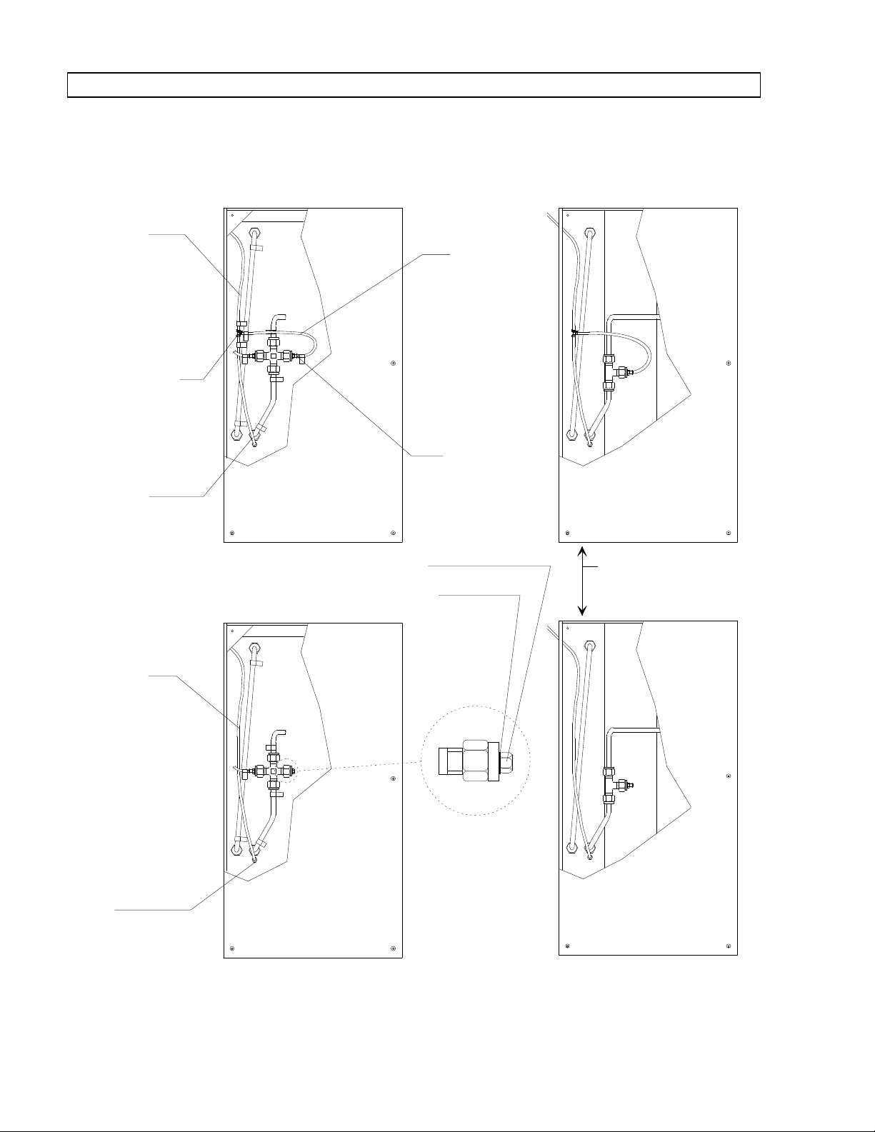
REAR VIEW OF FLOWMETER HOUSING
TEE FITTING
(REMOVE)
TUBING
FROM O2
RESTRICTOR
(REMOVE)
TUBING
FROM
ORMC TO O2
RESTRICTOR
(INSTALL)
PLUG (INSTALL)
WASHER (INSTALL)
O2
RESTRICTOR
CONNECTION
TUBING
(REMOVE)
HOSE BARB
FITTING
(REMOVE)
EARLIER MACHINES
CONFIGURED WITH
3-WAY FITTING
SP89001
TUBING
FROM
ORMC
(REMOVE)
RETURN TO SERVICE PROCEDURE TABLE OF CONTENTS
RETURN TO CD-ROM TABLE OF CONTENTSRETURN TO CD-ROM TABLE OF CONTENTS
CONVERSION PROCEDURE: 2 GAS MACHINES (continued)
Figure 1: TUBING REMOVAL/INSTALLATION (MIN. O2FLOW ELIMINATION)
2
Page 3
SP89002
VAPOR BOX TOP VIEW
OXYGEN RATIO
MONITOR CONTROLLER
O2
CONNECTION
MPL SWITCH
ADJUSTMENT
(TURN CLOCKWISE TO
DECREASE SETPOINT)
RETURN TO SERVICE PROCEDURE TABLE OF CONTENTS
RETURN TO CD-ROM TABLE OF CONTENTSRETURN TO CD-ROM TABLE OF CONTENTS
CONVERSION PROCEDURE: 2 GAS MACHINES (continued)
Figure 2: ORMC O2CONNECTION AND MPL SWITCH LOCATION
3
Page 4

LABEL
FRONT VIEW OF MACHINE
7/8"
1/8"
SP89003
RETURN TO SERVICE PROCEDURE TABLE OF CONTENTS
RETURN TO CD-ROM TABLE OF CONTENTSRETURN TO CD-ROM TABLE OF CONTENTS
CONVERSION PROCEDURE: 2 GAS MACHINES (continued)
13. Open the N
several turns. Slowly open the O
flow control valve and observe the
O
O ratio alarm lamp.
2/N2
The alarm lamp should be lighted
when the N
ml/min.
Slowly close the O
valve; the alarm lamp should be off
when the N
ml/min.
O flow control valve
2
O flow is above 800
2
flow control
2
O flow is below 700
2
14. If necessary, adjusttheMPL switch
2
on the ORM or ORMC (see Figure
2) until the alarm lamp responds as
noted in Step 13.
15. Reinstall the vapor box back cover,
and reinstall the flowmeter housing
back cover.
16. Install the Minimum Flow
Elimination label on the front of
the machine at the top right of the
flowmeter housing - positioned as
shown in Figure 3.
17. Perform a complete PMS on the
machine.
Figure 3: MIN. O2FLOW ELIMINATION - LABEL LOCATION
4
Page 5

RETURN TO SERVICE PROCEDURE TABLE OF CONTENTS
RETURN TO CD-ROM TABLE OF CONTENTSRETURN TO CD-ROM TABLE OF CONTENTS
CONVERSION PROCEDURE: 3 AND 4 GAS MACHINES
1. Turn the System Power switch to
STANDBY and remove AC power
from the machine.
2. Close all cylinder valves and
disconnect all pipeline supplies.
3. Remove the back cover of the
flowmeter housing.
4. Remove the back cover of the vapor
box to gain access to the
ORM/ORMC.
5. Remove the press-on hose clamp
and disconnect the flexible tubing
from the side hose barb on the
minimum flow cut-off valve.
Refer to Figure 1 for machines with
Air.
Refer to Figure 2 for machines
without Air. (Earlier machines may
be configured as shown in the
alternate view.)
8. Cut any tie straps securing the
flexible tubing, and remove the
tubing along with the associated tee
fitting.
9. Remove the hose barb fitting from
the minimum flow cut-off valve,
and install a washer (P/N 4102165)
and plug (P/N 4103801) as shown in
the lower view of Figure 1 and
Figure 2.
10. Connect a 35 in. length of flexible
tubing (P/N ML08003) and press-on
hose clamp to the hose barb at the
O
restrictor housing.
2
11. Connect the other end of the tubing
to the hose barb at the O
port on
2
the ORM or ORMC. Install a green
O
label (PN 4109871) at each end
2
of the tubing.
12. Restore power to the machine and
re-connect the pipeline supplies (or
open the cylinder valves).
6. Remove the press-on hose clamp
and disconnect the flexible tubing
from the hose barb at the O
restrictor housing.
7. Remove the press-on hose clamp
and disconnect the flexible tubing
from the O
port at the ORM or
2
ORMC. See Figure 3.
NOTE: For later machines without
the O
2
lamp, skip to Step 15.
13. Open the N
several turns. Slowly open the O
O ratio alarm
2/N2
O flow control valve
2
2
flow control valve and observe the
O
O ratio alarm lamp.
2/N2
5
Page 6

CONVERSION PROCEDURE: 3 AND 4 GAS MACHINES (continued)
REAR VIEW OF FLOWMETER HOUSING
TUBING FROM
ORMC (REMOVE)
TEE FITTING
(REMOVE)
TUBING FROM
O2 RESTRICTOR
(REMOVE)
TUBING FROM
ORMC TO O2
RESTRICTOR
(INSTALL)
PLUG
(INSTALL)
WASHER
(INSTALL)
O2 RESTRICTOR
CONNECTION
TUBING (REMOVE)
HOSE BARB
FITTING (REMOVE)
MINIMUM FLOW
CUTOFF VALVE
SP90002
RETURN TO SERVICE PROCEDURE TABLE OF CONTENTS
RETURN TO CD-ROM TABLE OF CONTENTSRETURN TO CD-ROM TABLE OF CONTENTS
Figure 1: TUBING REMOVAL/INSTALLATION,3&4GASMACHINES WITH AIR
(MIN. O
FLOW ELIMINATION)
2
6
Page 7

RETURN TO SERVICE PROCEDURE TABLE OF CONTENTS
RETURN TO CD-ROM TABLE OF CONTENTSRETURN TO CD-ROM TABLE OF CONTENTS
CONVERSION PROCEDURE 3 AND 4 GAS MACHINES (continued)
REAR VIEW OF FLOWMET ER HOU SING
MINIMUM FLOW
CUTOFF VALVE
TUBING FROM
ORMC (REMOVE)
TEE FITTIN G
(REMOVE)
TUBING (REMOVE)
HOSE BARB
FITTING (REMOVE)
TUBING FROM
O2 RESTRI CT OR
(REMOVE)
TUBING FROM
ORMC T O O2
RESTRICT OR
(INSTALL)
PLUG
(INSTALL)
EARLIER MACHINE
CONFI GURA T I ON
WASHER
(INSTALL)
O2 REST RI CT OR
CONNECTION
SP90001
Figure 2: TUBING REMOVAL/INSTALLATION,3&4GASMACHINES WITHOUT AIR
(MIN. O
FLOW ELIMINATION)
2
7
Page 8

SP89002
VAPOR BOX TOP VIEW
OXYGEN RATIO
MONITOR CONTROLLER
O2
CONNECTION
MPL SWITCH
ADJUSTMENT
(TURN CLOCKWISE TO
DECREASE SETPOINT)
RETURN TO SERVICE PROCEDURE TABLE OF CONTENTS
RETURN TO CD-ROM TABLE OF CONTENTSRETURN TO CD-ROM TABLE OF CONTENTS
CONVERSION PROCEDURE: 3 AND 4 GAS MACHINES (continued)
Figure 3: ORMC O2CONNECTION AND MPL SWITCH LOCATION
8
Page 9

LABEL
FRONT VIEW OF MACHINE
7/8"
1/8"
SP89003
RETURN TO SERVICE PROCEDURE TABLE OF CONTENTS
RETURN TO CD-ROM TABLE OF CONTENTSRETURN TO CD-ROM TABLE OF CONTENTS
CONVERSION PROCEDURE: 3 AND 4 GAS MACHINES (continued)
The alarm lamp should be lighted
when the N
O flow is above 800
2
ml/min.
Slowly close the O
flow control
2
valve; the alarm lamp should be off
when the N
O flow is below 700
2
ml/min.
14. If necessary, adjust the MPL switch
on the ORM or ORMC (see Figure
3) until the alarm lamp responds as
noted in Step 13.
15. Reinstall the vapor box back cover,
and reinstall the flowmeter housing
back cover.
16. Install the Minimum O
2
Flow
Elimination label on the front of
the machine at the top right of the
flowmeter housing - positioned as
shown in Figure 4.
17. Perform a complete PMS on the
machine.
Figure 4: MIN. O2FLOW ELIMINATION - LABEL LOCATION
9
Page 10

NORTH
RETURN TO SERVICE PROCEDURE TABLE OF CONTENTS
RETURN TO CD-ROM TABLE OF CONTENTSRETURN TO CD-ROM TABLE OF CONTENTS
AMERICAN
DRÄGER
Technical Service Department
3122 Commerce Drive
Telford, PA 18969
(215) 721-5402
(800) 543-5047
(215) 723-5935 Fax
Quality Service for Life
SM
Part Number: SP00089
Rev: B
Date: July 10, 1996
© 1996 N.A.D., Inc.
 Loading...