

Page 1

Installation and Operation Manual
RTU-292
RADIO / TELEPHONE
INTERFACE UNIT
Designed and Manufactured by:
JPS Communications, Inc.
5800 Departure Drive
Raleigh, NC 27616
e-mail: jps@jps.com
JPS P/N 5970-600200 Revision 1.62 July, 2005
1 JPS Communications, Inc.
Page 2

RTU-292 Operations Manual
JPS Communications, Inc. warrants its manufactured equipment to
be free from defects in materials and workmanship, and to conform
to published specifications for a period of 18 months from the date
of shipment from the factory or 12 months from installation,
whichever occurs first.
JPS warrants its service work performed in connection with this
warranty to be free from defects in materials and workmanship for
a period of 90 days from the date the work is performed.
If a defect occurs within the warranty period, the buyer shall notify
JPS immediately. JPS will repair or replace the equipment at its
option, upon return of the equipment; shipping prepaid, to the JPS
facility in Raleigh, North Carolina, USA
This warranty does not apply to damage caused by accidents,
abuse or improper installation.
Warranty
NO OTHER WARRANTY, EXPRESSED OR IMPLIED,
INCLUDING BUT NOT LIMITED TO THE IMPLIED
WARRANTIES OF MERCHANTABILITY AND FITNESS
FOR A PARTICULAR PURPOSE, SHALL APPLY.
NOTICE
JPS Communications, Inc. reserves the right to make changes to
the equipment and specifications without prior notice.
PROPRIETARY STATEMENT
The information contained in this manual is the property of JPS
Communications, Inc. and is intended for the purchaser’s use only.
It may not be reproduced without the express written consent of
JPS Communications.
Phone: (919) 790-1011
Fax: (919) 790-1456
e-mail: jps@jps.com
5800 Departure Drive
Raleigh, NC 27616
JPS Communications, Inc.
2
Page 3

RTU-292 Operations Manual
Table of Contents
1 GENERAL INFORMATION ...................................................................................................................... 1-1
1.1 SCOPE ....................................................................................................................................................1-1
1.2 DESCRIPTION....................................................................................................................................... 1-1
1.2.1 GENERAL...................................................................................................................................... 1-1
1.3 ASSEMBLIES ........................................................................................................................................ 1-2
1.3.1 MAIN BOARD ............................................................................................................................... 1-2
1.3.2 FRONT PANEL SWITCH ASSEMBLIES .................................................................................... 1-3
1.3.3 OPTIONS INTERFACE BOARD.................................................................................................. 1-3
1.3.4 OPTIONS........................................................................................................................................ 1-5
2 INSTALLATION.......................................................................................................................................... 2-1
2.1 GENERAL.............................................................................................................................................. 2-1
2.2 UNPACKING AND INSPECTION ....................................................................................................... 2-1
2.3 RESHIPMENT OF EQUIPMENT..........................................................................................................2-1
2.4 INSTALLATION OVERVIEW ............................................................................................................. 2-2
2.5 INSTALLATION CONSIDERATIONS ................................................................................................ 2-2
2.5.1 FCC PART 68 REGULATIONS ....................................................................................................2-2
2.6 POWER REQUIREMENTS ................................................................................................................... 2-4
2.7 INPUT POWER SELECTION ...............................................................................................................2-4
2.7.1 LINE VOLTAGE SELECTION ..................................................................................................... 2-4
2.7.2 DC INPUT POWER SELECTION................................................................................................. 2-4
2.8 CONFIGURING THE RTU-292 ............................................................................................................ 2-5
2.8.1 PROGRAMMING MODE SETUP PARAMETERS ..................................................................... 2-5
2.8.2 SETTING TELEPHONE SEND AND RECEIVE LEVELS..........................................................2-5
2.8.3 VOX HANGTIME.......................................................................................................................... 2-7
2.8.4 VOX SENSITIVITY....................................................................................................................... 2-7
2.8.5 BALANCED/UNBALANCED RADIO INTERFACE..................................................................2-7
2.8.6 RX LINE INPUT IMPEDANCE .................................................................................................... 2-8
2.8.7 DIAL MODE .................................................................................................................................. 2-8
2.8.8 TELEPHONE RING VOLUME.....................................................................................................2-8
2.8.9 FULL/HALF DUPLEX RADIO.....................................................................................................2-8
2.8.10 SERIAL PORT BAUD RATE........................................................................................................ 2-9
2.8.11 RADIO CONTROL MODE............................................................................................................2-9
2.8.12 PASSWORD PROTECTION ....................................................................................................... 2-10
2.8.13 VOICE PROMPTS ....................................................................................................................... 2-10
2.8.14 LOCAL PHONE / LOCAL PHONE RING-THROUGH ............................................................. 2-10
2.8.15 TRANSMIT LEVEL SET-UP MODE..........................................................................................2-11
2.8.16 MISCELLANEOUS JUMPERS...................................................................................................2-11
2.9 INTERCONNECT INFORMATION ...................................................................................................2-11
2.9.1 TELEPHONE CONNECTION..................................................................................................... 2-12
2.9.2 RADIO CONNECTION ............................................................................................................... 2-12
2.9.3 HANDSET CONNECTOR........................................................................................................... 2-13
2.9.4 TERMINAL BLOCK.................................................................................................................... 2-14
2.9.5 RS-232 CONNECTION................................................................................................................ 2-15
2.10 AUDIO LEVEL SETUP AND ADJUSTMENTS ................................................................................ 2-15
2.10.1 SETTING THE TRANSMIT LEVEL...........................................................................................2-15
2.10.2 SETTING THE RECEIVE LEVEL.............................................................................................. 2-16
2.11 INSTALLATION CHECKLIST........................................................................................................... 2-24
2.12 OPTIONS INSTALLATION AND CONFIGURATION..................................................................... 2-24
3 OPERATION ................................................................................................................................................3-1
JPS Communications, Inc.
3
Page 4

RTU-292 Operations Manual
3.1 GENERAL ..............................................................................................................................................3-1
3.2 FRONT PANEL CONTROLS, INDICATORS AND CONNECTORS.................................................3-1
3.2.1 MAIN POWER SWITCH ...............................................................................................................3-1
3.2.2 HEADPHONE JACK......................................................................................................................3-1
3.2.3 HANDSET JACK ...........................................................................................................................3-1
3.2.4 HANDSET ......................................................................................................................................3-1
3.2.5 SPEAKER .......................................................................................................................................3-1
3.2.6 KEYPAD.........................................................................................................................................3-2
3.2.7 SPEAKER VOLUME CONTROL..................................................................................................3-2
3.2.8 PHONES VOLUME CONTROL....................................................................................................3-2
3.2.9 TEL LINE BUTTONS ....................................................................................................................3-2
3.2.10 HANDSET BUTTONS...................................................................................................................3-2
3.2.11 SPEAKER BUTTONS....................................................................................................................3-3
3.2.12 TEL VOX........................................................................................................................................3-3
3.2.13 AUTO ANS BUTTON....................................................................................................................3-3
3.2.14 AUDIBLE RING BUTTON............................................................................................................3-3
3.2.15 KEY PUSHBUTTON .....................................................................................................................3-3
3.2.16 PEAK LED......................................................................................................................................3-3
3.3 REAR PANEL CONNECTORS .............................................................................................................3-4
3.3.1 P1 RADIO CONNECTOR..............................................................................................................3-4
3.3.2 J1 TEL LINE...................................................................................................................................3-4
3.3.3 TERMINAL BLOCK......................................................................................................................3-4
3.3.4 J2 LOCAL PHONE CONNECTOR................................................................................................3-4
3.3.5 P2 RS-232 CONNECTOR .............................................................................................................3-4
3.3.6 DC INPUT TERMINAL BLOCK...................................................................................................3-4
3.3.7 P1 AC POWER CONNECTOR .....................................................................................................3-4
3.4 OPERATION ..........................................................................................................................................3-5
3.4.1 OPERATION OVERVIEW ............................................................................................................3-5
3.4.2 USE OF THE RTU-292 SPEAKER TO MONITOR AUDIO ........................................................3-5
3.4.3 PLACING A TELEPHONE CALL.................................................................................................3-5
3.4.4 RECEIVING A TELEPHONE CALL ............................................................................................3-6
3.4.5 PUTTING A TELEPHONE CALL ON HOLD..............................................................................3-6
3.4.6 USING THE HANDSET WITH THE RADIO...............................................................................3-6
3.4.7 CONNECTING THE RADIO TO THE TELEPHONE LINE........................................................3-6
3.4.8 MANUAL PHONE PATCH PROCEDURE...................................................................................3-7
3.4.9 TRANSMITTER KEYING, HALF DUPLEX SYSTEM ...............................................................3-8
3.4.10 TRANSMITTER KEYING, FULL DUPLEX SYSTEM................................................................3-9
3.5 REMOTE KEY .......................................................................................................................................3-9
3.6 SELF TEST .............................................................................................................................................3-9
3.7 AUTOMATED OPERATION ................................................................................................................3-9
3.7.1 TONE PROMPTS ...........................................................................................................................3-9
3.7.2 VOICE PROMPTS........................................................................................................................3-10
3.7.3 CALLING THE RTU-292 VIA THE OUTSIDE LINE................................................................ 3-10
3.7.4 PLACING A CALL IN THE COMMAND MODE:.....................................................................3-12
3.7.5 TERMINATING A CALL:...........................................................................................................3-12
3.7.6 DTMF CONTROL COMMANDS................................................................................................3-13
3.7.7 RTU-292 PASSWORD PROTECTION .......................................................................................3-16
3.7.8 INACTIVITY DISCONNECT TIMER ........................................................................................3-16
3.7.9 CALLING TIMER ........................................................................................................................3-16
3.7.10 USING THE RTU-292 SPEED DIAL FEATURE .......................................................................3-17
3.7.11 OPTIONAL 4 WIRE OPERATION .............................................................................................3-18
3.8 FACTORY RESET ............................................................................................................................... 3-18
3.9 SPEED DIAL RESET ...........................................................................................................................3-18
4 RTU-292 THEORY OF OPERATION .....................................................................................................4-19
4.1 GENERAL ............................................................................................................................................4-19
JPS Communications, Inc.
4
Page 5

RTU-292 Operations Manual
4.2 FRONT PANEL BUTTONS AND INDICATORS.............................................................................. 4-19
4.3 MAIN BOARD ..................................................................................................................................... 4-19
4.3.1 AUDIO BUS ARRANGEMENT.................................................................................................. 4-19
4.3.2 TELEPHONE INTERFACE CIRCUITS...................................................................................... 4-20
4.3.3 RADIO INTERFACE CIRCUITS................................................................................................ 4-21
4.3.4 HANDSET/ SPEAKER INTERFACE.........................................................................................4-22
4.3.5 DSP MODULE ............................................................................................................................. 4-22
4.3.6 DSP SOFTWARE.........................................................................................................................4-22
4.3.7 POWER SUPPLY.........................................................................................................................4-24
4.3.8 CPU...............................................................................................................................................4-24
4.3.9 PROMPT TONE GENERATOR .................................................................................................. 4-25
4.4 OPTION INTERFACE BOARD .......................................................................................................... 4-25
4.5 VOICE PROMPT OPTION.................................................................................................................. 4-25
4.5.1 SPEECH PROCESSOR................................................................................................................ 4-25
4.5.2 CONTROL PROCESSOR ............................................................................................................ 4-25
4.5.3 VOICE PROMPT SOFTWARE ................................................................................................... 4-26
4.6 LOCAL PHONE OPTION ................................................................................................................... 4-26
4.6.1 INTERFACE CIRCUITRY .......................................................................................................... 4-26
4.6.2 DIAL/BUSY GENERATORS ......................................................................................................4-26
4.6.3 LOCAL TELEPHONE LINE INTERFACE.................................................................................4-26
5 REMOTE CONTROL PROTOCOL.......................................................................................................... 5-1
5.1 GENERAL.............................................................................................................................................. 5-1
5.2 RS-232 REMOTE CONTROL OVERVIEW......................................................................................... 5-1
5.3 COMMANDS SENT TO THE RTU-292 ............................................................................................... 5-1
5.3.1 NULL Command ............................................................................................................................ 5-3
5.3.2 Auto Answer Command.................................................................................................................. 5-3
5.3.3 Audible Ring Command.................................................................................................................. 5-3
5.3.4 Date Command................................................................................................................................ 5-4
5.3.5 Dial Command ................................................................................................................................ 5-4
5.3.6 Disconnect Command ..................................................................................................................... 5-5
5.3.7 DTMF Command............................................................................................................................ 5-5
5.3.8 Handset Phone Command ............................................................................................................... 5-6
5.3.9 Handset Radio Command................................................................................................................ 5-6
5.3.10 Speaker Phone Command ............................................................................................................... 5-7
5.3.11 Speaker Radio Command................................................................................................................ 5-7
5.3.12 Speed Dial Command......................................................................................................................5-8
5.3.13 Tel-Line Phone Command .............................................................................................................. 5-9
5.3.14 Tel-Line Radio Command............................................................................................................... 5-9
5.3.15 Time Command............................................................................................................................. 5-10
5.3.16 Software Version Command......................................................................................................... 5-10
5.4 STATUS RETURNED FROM THE RTU-292.................................................................................... 5-11
5.4.1 NULL Response............................................................................................................................ 5-12
5.4.2 Auto Answer Response ................................................................................................................. 5-12
5.4.3 Call Starting Response .................................................................................................................. 5-12
5.4.4 Dial Response................................................................................................................................ 5-13
5.4.5 Disconnect Response ....................................................................................................................5-13
5.4.6 DTMF Response ...........................................................................................................................5-13
5.4.7 Elapsed Time Response ................................................................................................................5-14
5.4.8 Handset Phone Response ..............................................................................................................5-14
5.4.9 Handset Radio Response............................................................................................................... 5-14
5.4.10 Speaker Phone Response............................................................................................................... 5-15
5.4.11 Speaker Radio Response............................................................................................................... 5-15
5.4.12 Speed Dial Response..................................................................................................................... 5-16
5.4.13 Tel-Line Phone Response.............................................................................................................. 5-16
5.4.14 Tel-Line Radio Response.............................................................................................................. 5-16
JPS Communications, Inc.
5
Page 6

RTU-292 Operations Manual
5.4.15 Time/Date Response......................................................................................................................5-17
5.4.16 Version Response ..........................................................................................................................5-17
5.5 CALL PROGRESS RESPONSES FROM THE RTU-292 ...................................................................5-18
5.6 RESPONSE ERROR CODES............................................................................................................... 5-18
6 MAINTENANCE AND REPAIR ..............................................................................................................6-19
6.1 GENERAL ............................................................................................................................................6-19
6.2 PREVENTIVE MAINTENANCE ........................................................................................................ 6-19
6.3 REPAIR OR REPLACEMENT ............................................................................................................6-19
6.3.1 GENERAL PRECAUTIONS AND NOTES.................................................................................6-19
6.4 ALIGNMENT .......................................................................................................................................6-19
6.5 PERFORMANCE TESTING................................................................................................................6-19
6.5.1 TEST EQUIPMENT REQUIRED ................................................................................................6-19
6.5.2 HYBRID BALANCE MEASUREMENT.....................................................................................6-20
6.5.3 VOX SENSITIVITY MEASUREMENT......................................................................................6-23
7 RTU-292 OPTIONS ......................................................................................................................................7-1
7.1 GENERAL ..............................................................................................................................................7-1
7.1.1 Special Software Versions...............................................................................................................7-1
7.2 VOICE PROMPT OPTION ....................................................................................................................7-2
7.2.1 INSTALLATION AND CONFIGURATION................................................................................. 7-2
7.2.2 OPERATION ..................................................................................................................................7-2
7.3 LOCAL PHONE OPTION......................................................................................................................7-4
7.3.1 LOCAL PHONE OPTION INSTALLATION AND CONFIGURATION.....................................7-4
7.3.2 LOCAL PHONE OPTION OPERATION ......................................................................................7-5
7.4 VMM-100 OPTION ................................................................................................................................7-6
7.4.1 VMM-100 Hardware.......................................................................................................................7-6
7.4.2 VMM-100 Software ........................................................................................................................7-7
7.4.3 VMM-100 INSTALLATION AND CONFIGURATION...............................................................7-7
7.5 DTMF ACCESS OPTION ....................................................................................................................7-11
7.5.1 Initiate Call Via Attention Signal .................................................................................................. 7-11
7.5.2 RTU-292 Response to Attention Signal ........................................................................................7-11
7.5.3 Radio Caller Provides Calling Directions......................................................................................7-11
7.5.4 RTU-292 Plays Back Phone Number & Prompts for Confirmation..............................................7-11
7.5.5 RTU-292 Places the Call ...............................................................................................................7-11
7.5.6 After the Call Begins .....................................................................................................................7-12
7.6 SQUELCH BREAK ACCESS OPTION...............................................................................................7-13
7.6.1 Initiate Call Via Attention Signal .................................................................................................. 7-13
7.6.2 RTU-292 Response to Attention Signal ........................................................................................7-13
7.6.3 RTU-292 Prompts for Confirmation .............................................................................................7-13
7.6.4 RTU-292 Places the Call ...............................................................................................................7-13
7.6.5 After the Call Begins .....................................................................................................................7-13
7.7 THE CALL LOGGING OPTION.........................................................................................................7-14
7.7.1 Checking The Time And Date....................................................................................................... 7-14
7.7.2 Setting The Time ...........................................................................................................................7-14
7.7.3 Setting The Date............................................................................................................................7-14
7.7.4 Call Logging..................................................................................................................................7-14
7.8 RADIO CONTROL OPTION...............................................................................................................7-15
7.8.1 CONTROLLING THE RADIO VIA THE RTU-292 FRONT PANEL KEYPAD.......................7-15
8 SCHEMATIC DIAGRAMS .........................................................................................................................8-1
8.1 GENERAL ..............................................................................................................................................8-1
9 INDEX............................................................................................................................................................9-1
JPS Communications, Inc.
6
Page 7

RTU-292 Operations Manual
List Of Figures
FIGURE 2-1 OUTLINE DIMENSIONS ................................................................................................................... 2-18
F
IGURE 2-2 CONTROL AND CONNECTOR LOCATIONS ....................................................................................... 2-19
F
IGURE 2-3 LOCATION OF INTERNAL OPTION SETTINGS .................................................................................. 2-20
FIGURE 2-4 INTERNAL OPTION SETTING DETAILS ............................................................................................ 2-21
FIGURE 2-5 AUDIO INTERFACE WIRING DIAGRAM ........................................................................................... 2-22
F
IGURE 2-6 INTERFACE DETAILS ......................................................................................................................2-23
FIGURE 6-1 HYBRID BALANCE TEST SET-UP....................................................................................................6-21
FIGURE 6-2 VOX SENSITIVITY TEST SET-UP ................................................................................................... 6-23
FIGURE 7-1 VOICE PROMPT OPTION INSTALLATION ........................................................................................... 7-3
IGURE 7-2 LOCAL PHONE OPTION INSTALLATION............................................................................................. 7-5
F
F
IGURE 7-3 VMM-100 OPTION INSTALLATION .................................................................................................. 7-8
FIGURE 8-1 FRONT PANEL SCHEMATIC............................................................................................................... 8-1
FIGURE 8-2 MAIN BOARD SCHEMATIC ............................................................................................................... 8-1
FIGURE 8-3 DSP MODULE ..................................................................................................................................8-1
FIGURE 8-4 OPTION INTERFACE BOARD ............................................................................................................. 8-1
FIGURE 8-5 VOICE PROMPT OPTION BOARD ....................................................................................................... 8-1
FIGURE 8-6 LOCAL PHONE OPTION BOARD ........................................................................................................ 8-1
FIGURE 8-7 VMM-100 OPTION BOARD .............................................................................................................. 8-1
JPS Communications, Inc.
7
Page 8

RTU-292 Operations Manual
List of Tables
TABLE 1-1 EQUIPMENT AND ACCESSORIES SUPPLIED ....................................................................................1-4
TABLE 1-2 OPTIONAL EQUIPMENT - NOT SUPPLIED ........................................................................................1-5
TABLE 1-3 RTU-292 SPECIFICATIONS.......................................................................................................1-6
TABLE 2-1 RTU-292 FACTORY DEFAULT SETTINGS.......................................................................................2-3
TABLE 2-2 RECOMMENDED PHONE LINE SETTINGS ........................................................................................2-6
TABLE 2-3 TELEPHONE SEND/RECEIVE LEVELS..............................................................................................2-6
TABLE 2-4 VOX HANGTIME ..............................................................................................................................2-7
TABLE 2-5 VOX SENSITIVITY ...........................................................................................................................2-7
TABLE 2-6 DIAL MODE ......................................................................................................................................2-8
TABLE 2-7 FULL/HALF DUPLEX.........................................................................................................................2-9
TABLE 2-8 BAUD RATE......................................................................................................................................2-9
TABLE 2-9 RADIO CONTROL MODE ...................................................................................................................2-9
TABLE 2-10 PASSWORD PROTECTION..............................................................................................................2-10
TABLE 2-11 VOICE PROMPTS ENABLE .............................................................................................................2-10
TABLE 2-12 LOCAL PHONE ENABLE .................................................................................................................2-11
TABLE 2-13 LOCAL PHONE RINGTHROUGH......................................................................................................2-11
TABLE 2-14 TX LEVEL SET-UP MODE..............................................................................................................2-11
TABLE 2-15 J1 - TEL LINE (RJ-11C).............................................................................................................2-12
TABLE 2-16 P1-RADIO (DB-9 MALE) ............................................................................................................2-13
TABLE 2-17 J7 - HANDSET (RJ12C JACK)...................................................................................................2-13
TABLE 2-18 TERMINAL BLOCK (6 POSITION)....................................................................................................2-14
TABLE 2-19 P2 – RS-232 CONNECTOR (DB-9 MALE) ...................................................................................2-15
TABLE 2-20 INSTALLATION CHECKLIST.............................................................................................................2-24
TABLE 3-1 STANDARD DTMF OPERATIONAL COMMANDS ............................................................................3-14
TABLE 3-2 PROGRAMMING MODE DTMF COMMANDS ..................................................................................3-15
TABLE 5-1 COMMAND SUMMARY...................................................................................................................... 5-2
TABLE 5-2 RESPONSE SUMMARY...................................................................................................................5-11
TABLE 5-3 CALL PROGRESS RESPONSES......................................................................................................5-18
TABLE 5-4 RESPONSE ERROR CODES...........................................................................................................5-18
TABLE 6-1 FAULT ANALYSIS ...........................................................................................................................6-24
TABLE 7-1 RTU-292 OPTIONS..........................................................................................................................7-1
TABLE 7-2 VOICE PROMPTS ENABLE ...............................................................................................................7-2
TABLE 7-3 LOCAL PHONE ENABLE ...................................................................................................................7-4
TABLE 7-4 LOCAL PHONE RINGTHROUGH........................................................................................................ 7-4
TABLE 7-5 LOCAL PHONE DTMF COMMANDS.................................................................................................7-5
TABLE 7-6 VMM-100 SPECIFICATIONS .....................................................................................................7-9
TABLE 7-7 VMM-100 I/O CONNECTOR INFORMATION (P9) ...............................................................7-10
TABLE 7-8 VMM-100 SWITCH FUNCTIONS....................................................................................................7-10
TABLE 7-9 DTMF RADIO CONTROL COMMANDS........................................................................................... 7-16
JPS Communications, Inc.
8
Page 9

RTU-292 Operations Manual
Glossary
Adaptation
COR
COS
CTCSS
DIP Switch
DTMF
DSP
EIA
Full Duplex
Half Duplex
Hangtime
Key
LED
LMR
Mute
PCB
PTT
RX
Simplex
SNR
Squelch
TX
VMR
VOX
The process whereby the RTU-292 DSP algorithms detect reflected signal information in a
connected line and tune the DSP hybrid for a broadband null with minimum reflection.
Carrier Operated Relay - A receiver signal that gives a positive indication that a carrier or signal
is being received and that the receiver is unsquelched. Same as COS.
Carrier Operated Squelch - See COR.
Continuous Tone Controlled Squelch System. A squelch system using EIA Standardized subaudible tones in the 67Hz to 250Hz frequency range. An FM squelch which opens only when
the proper sub-audible tone is present.
Dual In-Line Package Switch (Also “dipswitch”)- A multi-unit switch that fits into a standard
DIP integrated circuit footprint. It usually contains eight or ten individual switches.
Dual Tone Multi Frequency - The standard touch-tone telephone dialing method.
Digital Signal Processing (or Processor).
Electronic Industries Association.
A communications system that can operate in transmit mode and receive mode simultaneously,
with different frequencies for transmit and receive. See also Half Duplex and Simplex.
A communications system that uses different frequencies for transmit and receive operation, but
can not transmit and receive at the same time. See also Full Duplex and Simplex.
A system with hangtime will remain in the transmit mode for the duration of the set hangtime
beyond the time indicated by any keying inputs. The hangtime prevents transmitter unkey
during brief pauses in the transmission.
To key a transmitter means to cause it to transmit.
Light Emitting Diode.
Land Mobile Radio.
To quiet or inhibit audio.
Printed Circuit Board.
Push-to-Talk. An active PTT signal causes a transmitter to key.
Receiver or Receiving.
A communications system that uses the same frequencies for both transmit and receive
operation. A simplex system can obviously not transmit and receive simultaneously. See also
Full Duplex and Half Duplex.
Signal-to-Noise Ratio.
A means of detecting audio and causing some action when it is present, such as keying a
transmitter or unmuting an audio path.
Transmit or Transmitter.
Voice Modulation Recognition. A type of squelch, which is activated only by spoken words and
not by tones, noise, or other audio information.
Voice Operated Xmit (Transmit). A circuit or algorithm that causes a transmitter to key or some
other action when voice or other signal is present. This squelch type is activated by any audio
signal, and is not restricted to voice only.
JPS Communications, Inc.
9
Page 10

RTU-292 Operations Manual
This page intentionally left blank.
JPS Communications, Inc.
10
Page 11

RTU-292 Operations Manual
1 General Information
1.1 SCOPE
This instruction manual provides the information necessary to install, operate, repair and
maintain the RTU-292 Radio/Telephone Interface.
1.2 DESCRIPTION
1.2.1 GENERAL
The RTU-292 Radio/Telephone Interface Unit will provide a trouble-free automatic connection
between a radio system and telephone or other two-wire line. The unit is suited for use with
HF, VHF, UHF or satellite systems and is applicable to full or half-duplex modes. The RTU292 incorporates a full-featured telephone set and monitor speaker. Flexible switching allows
many operating scenarios.
The RTU-292 replaces the JPS Communications RTU-282. The RTU-292 contains all of the
features and capabilities of the RTU-282, along with some major improvements. The new DSP
used in the RTU-292 allows improved Call Progress Detection. Additional circuitry on the
Main Board provides the ability to detect line reversal when a telephone caller hangs up the
phone, allowing immediate call termination when used with phone systems that have Reverse
Battery Signaling. A new standard feature with the RTU-292 is RS-232 control of the unit. A
new optional feature is DTMF Access of the system via radio.
A front panel keypad allows DTMF or Pulse dialing and the built-in handset is pushbuttonselectable for communication with either the telephone or the radio. Since the telephone may
place and receive calls, the operator can quickly and easily establish a phone patch connection.
When used in the manual mode, the RTU-292 patches a telephone into a radio link by
essentially the same method as with a conventional phone patch; the quality of the patch,
however is greatly improved. First, a radio-to-radio link is established. Then, using the
telephone in the RTU-292, the operator places a phone call to the distant telephone that will be
patched into the radio link. Once the telephone-to-telephone link is made, the operator simply
pushes a front panel pushbutton. The RTU-292 adapts to the phone line, and the distant phone
becomes part of a telephone-to-radio-to-radio communications link. Once this link is
established, the operator may communicate with either party using the RTU-292’s handset, and
may monitor both sides of the conversation with the speaker.
The RTU-292 uses a unique adaptive hybrid implemented with a DSP (Digital Signal
Processor) to eliminate conventional VOX and hybrid adjustments for a quick and simple setup. The unit works by measuring the characteristics of the telephone line. A short burst of
white noise is placed on the telephone line. During this burst, the adaptive hybrid in the unit
measures the signal reflected from the phone line and adapts the RTU-292 to the impedance of
the phone line, minimizing the reflected signal. This achieves a broadband hybrid balance on
the reactive phone line. This is simply not possible with any type of conventional active or
passive hybrid. Not only is a deep, broadband null provided, but also the action is completely
JPS Communications, Inc.
1-1
Page 12

RTU-292 Operations Manual
automatic. The unit will continuously adapt to changing line conditions, making operation
insensitive to line impedance changes.
In the Automated Operations mode, the RTU-292 combines the unique features of its adaptive
DSP hybrid with fully unmanned auto-dial/auto-answer capability. In its standard
configuration, the unit uses tone prompts to signal the remote user of the operations that must
be performed to control the unmanned radio station. The addition of a Voice Prompt Option
supplies a large number of spoken prompts to simplify control. The Local Phone Option allows
a standard telephone set to be plugged into the rear panel of the RTU-292; this local phone may
then be used in place of the unit's keypad and handset.
Input and output levels are internally adjustable to accommodate all types of radio systems. A
set-up mode allows the adjustment of the RTU-292 receiver and transmitter signal levels
without any external test equipment.
The unit will interface all types of two-wire lines, such as normal dial-up lines, dedicated lines,
or twisted-pair field wire. Although the output impedance is fixed at 600 Ohms, the adaptive
hybrid in the unit will give excellent hybrid balance regardless of the impedance of the line
connected to the unit.
The unit operates from 115 or 230 VAC, 47 to 63 Hz, or from +12 or +24/+28 VDC nominal;
the +12VDC range extends from +11 to +15 VDC, while the +24/+28 VDC range extends from
+22 to +30 VDC. It is packaged in a rugged enclosure measuring 3.5"H x 19"W x 12"D. All
inputs and outputs, including those for power, are filtered or protected as appropriate to enable
the RTU-292 to meet the requirements of FCC Part 15 rules for a Class A Digital Device.
1.3 ASSEMBLIES
The standard RTU-292 contains five PC board assemblies; the main board (with plug-on
adaptive hybrid DSP board), three front panel switch PC board assemblies, and the Options
Interface Board, which is mounted in the Options Tray where other option boards may be
installed. Mounted on the front panel along with the switchboards are a speaker, control
potentiometers, phone jack and handset jack. The various I/O connectors and the DC power
input connector are accessible via the rear panel.
1.3.1 MAIN BOARD
The main board has six general sections of circuitry: the Telephone Interface section,
Handset/Speaker Interface section, Radio Interface section, DSP section, CPU section, and
Power Supply section. These are described briefly in the following paragraphs. Refer to the
RTU-292 block diagram along with the text. (The power supply and DSP sections are not
shown in the block diagram, refer to Section 4 for more details.)
1.3.1.1 Telephone Interface
The Telephone Interface Section has the amplifiers that drive and receive audio from the phone
line. This section also contains the DSP hybrid (which is detailed in Section 4 of this manual),
interfaced with the keypad. A tone ringer generates a warble audio tone when ring voltage is
received.
JPS Communications, Inc.
1-2
Page 13

RTU-292 Operations Manual
1.3.1.2 Handset/Speaker Interface
The Handset/Speaker Interface Section contains the speaker pre-amp and driver, the headphone
pre-amp and driver. Audio gates controlled by the front panel switches route the audio to the
speaker and handset microphone preamplifier and ALC (Automatic Level Control) circuit.
1.3.1.3 Radio Interface
The Radio Interface Section consists of operational amplifier circuits that handle the audio
interfaces between the RTU-292 and the radio. The amplifiers provide gain adjustability to
accommodate various input and output levels, and also provide impedance transformation and
output drive capability. Audio gates controlled by the front panel switches and the CPU route
the audio as desired by the operator.
1.3.1.4 DSP Module
The plug-in Digital Signal Processor (DSP) module is the heart of the unit, as the adaptive
hybrid is implemented with the DSP. From a hardware standpoint, the DSP section consists of
a DSP chip interfaced with dual analog interface ICs, static RAM for audio storage and delay,
and a program flash memory IC.
From a software standpoint, the following functions are implemented in software in the DSP
section: the adaptive hybrid, the VOX, an audio peak detector, the noise generator for
measuring the telephone line characteristics, an audio delay and the transmit setup tone
generator.
1.3.1.5 CPU Section
This section contains the microprocessor and program software that controls all operations of
the RTU-292. Various I/O devices read external inputs and the front panel controls. The
inputs are processed and audio gates, front panel LEDs, audio prompts, etc., are controlled
accordingly.
1.3.1.6 Power Supply Section
The power supply in the RTU-292 is a quiet and reliable passive regulator type. It furnishes
regulated voltages of +12V, -12V, +5V and -5V to the unit.
1.3.2 FRONT PANEL SWITCH ASSEMBLIES
There are three separate front panel switch assemblies that contain the pushbutton switches and
LED indicators for the RTU-292. Each of these assemblies contains a different complement of
components as required by its function. Signals from the switches are read by the CPU
circuitry on the main board. The processor then routes audio signals and lights the front panel
LEDs according to the pushbutton commands.
1.3.3 OPTIONS INTERFACE BOARD
This board, located on the Options Tray above the main board, contains the connectors used to
interface the main board to the various option boards that may be assembled to the Options
Tray.
JPS Communications, Inc.
1-3
Page 14

RTU-292 Operations Manual
Qty
Table 1-1 Equipment and Accessories Supplied
Qty Part Number Item
1 5970-600000 RTU-292 Standard
1 5970-600200 Operation & Maintenance Manual
1 5970-600150 Accessory Kit
Accessory Kit
Consists of:
Part Number Item
1 0150-200000 Handset, PTT, black
1 0313-037770 Cable, misc., power w/3-wire connector
1 0313-060000 Cord, coiled, black (for handset)
2 0360-009000 Connector, cable, DB-9 receptacle
2 0650-005100 Fuse, 3AG, 1/2A, slow blow
2 0650-010100 Fuse, 3AG, 1A, slow blow
2 0827-000001 HW, clamp, cable, for DB-9 connector
1 0827-102401 HW, Telephone Hanger; may be attached to front panel
9 0833-063205 HW, screw, flat head, 6-32 x 5/16”, 100 degrees,
5 0837-103200 HW, screw, truss head, #10-32x3/8, for mounting unit front
5 0848-100001 HW, washer, flat, nylon (#10 by ½” diameter by 1/16”
(holes provided)
(spares for top cover mounting)
panel to rack (includes one spare)
thick), for mounting unit front panel to rack (includes one
spare)
JPS Communications, Inc.
1-4
Page 15

RTU-292 Operations Manual
1.3.4 OPTIONS
RTU-292 options include the: The Voice Prompt Option, which gives verbal prompts to the
user as an aid in all aspects of unit operation; The Local Phone Option, which allows a DTMF
telephone set to be plugged into the unit, allowing control and access from the phone set; and
the VMM-100 module, used to add VMR (Voice Modulation Recognition) and DSP noise
reduction capability. Among the Software Options are the Squelch Break Access Option,
which allows a radio to contact the system via series of squelch breaks and the DTMF Access
Option, which allows a radio user to contact the system via a DTMF keypad. Other Software
Options include Call Logging and Remote Control of an URC-200 radio. Various spares kits
are also available. The STU-III option allows a STU-III phone to be connected to the RTU-
292. This allows an encrypted STU-III conversation to be decrypted at the RTU-292. The
decrypted signal is patched into the connected radio system.
Table 1-2 Optional Equipment - Not Supplied
Item JPS P/N Description
Depot Spares Kit 5970-691000 Spares for 3 to 5 RTU-292s
Spare PC Board Kit 5970-692000 Spare Boards for 1 unit
Spare Parts Kit 5970-693000 Spares for one RTU-292
Local Phone Option 5930-596000 Allows remote operation of the RTU-292 through the use of
a standard telephone set connected directly to the RTU-292
Local Phone port. (Telephone set and cable not supplied.)
DTMF Telephone Set 5930-599000 Telephone set for use with the Local Phone Option
Voice Prompt Option 5930-595000 Standard Version (English, female voice)
VMM-100 Option 5930-591100 Provides DSP Voice Modulation Recognition squelch and/or
DSP Noise Reduction to the radio RX input.
STU-III Option 5960-796000 Allows connection to a STU-III phone
Rack Slides Kit 5930-594000 1 set slides and hardware to rack-mount one RTU-292.
Software Options
Call Logging S/W Option 5970-791500 Provides record of calls via RS-232 interface.
Radio Control Option 5970-795000 Provides remote control of URC-200 radio via RS-232 int.
Squelch Break Access 5970-791300 Allows radio connection via series of squelch breaks
DTMF Access Option 5970-799000 Allows radio connection via DTMF keypad.
JPS Communications, Inc.
1-5
Page 16

RTU-292 Operations Manual
Table 1-3 RTU-292 SPECIFICATIONS
TELEPHONE LINE INTERFACE (J2, Male DB-9 Connector)
Output & Input Levels to Phone Line Nominally -12 dBm. (Adjustable -21 to 0 dBm in 3 dB steps).
Frequency Response +2 dB, 300 to 3200 Hz.
Output Impedance to Phone Line 600 Ohm .
VOX Sensitivity 16 +2 dB Below Phone Line Input Level Setting.
(-25 dBm @ -9 dBm Level Setting, for example)
VOX Hang Time 0.6 Second or 2.0 Seconds, (Internally Settable).
Hybrid Balance/Adaptation Speed
(into 600 Ohm)
Ultimate Hybrid Balance (into 600 Ohm) -50 dB typical over 300 to 3200 Hz BW; measured with a single
Hybrid Impedance Matching Capability 0 to 10k Ohm Complex Impedance.
Phone Line Connections RJ11C Connector (J1) and screw terminals on rear panel term
RADIO INTERFACE (J1, Male DB-9 Connector)
Input Impedance Balanced or Unbalanced 600 Ohm or Unbalanced 47K Ohm.
Input Level -40 to +10 dBm, Internally Adjustable.
Output Impedance 600 Ohm balanced.
Output Level -40 to +10 dBm, Internally Adjustable
Frequency Response 300 to 3200 Hz + 2 dB.
Key Relay Output Low Level Relay Contacts, 60VA max., Switching Speed: 5 msec.
TELEPHONE
Handset (RJ12C Jack) Electret microphone, dynamic receiver.
Dialing Modes DTMF, Pulse at 10 pps
Pulse Dial Make/Break Ratio 40/60.
Dialing Keypad 3x4, Standard Telephone Layout.
GENERAL
Microphone Interface ALC (Automatic Level Control) with 30 dB dynamic range.
Headphone Interface Drives high, medium, or low impedance headphones.
Phones Jack (monaural) Delivers NLT 10mW into 600-Ohm headphones.
Speaker Driver Power 4W min @ 10% Distortion.
Internal Speaker 3 inch square, 3.2 Ohms.
Indicators Peak Level, Keyed, and Indicator for each pushbutton.
Front Panel Controls Power Switch, Dialing Keypad, Speaker and Handset Volume
AC Input Power 115 or 230 VAC +/- 15%, 47-63 Hz, 20 VA typical, 50 VA max.
DC Input Power +11 to +15VDC or +22 to +30VDC, 1 A Maximum.
Size 3.5"H x 19"W x 10"D (8.9 x 48.3 x 25.4 cm)
Weight 12 lbs. (5.5 kg).
ENVIRONMENTAL
Operating Temperature -200 C to +550 C.
Storage Temperature -400 C to +850 C.
Humidity Up to 95% @ 550 C.
Shock MIL-STD-810D, method 516.3 procedure VI.
Vibration MIL STD 810D, method 514.3 Category I.
-30 dB over 300 to 3200 Hz BW within 1.25 Sec.; measured with
white noise source.
tone.
block.
Controls, Pushbuttons: Tel Line/Phone, Tel Line/Radio, Off,
Handset/Phone, Handset/Radio, Speaker/Phone, Speaker/Radio,
Tel VOX, Manual Key, Auto Answer, Audible Ring.
JPS Communications, Inc.
1-6
Page 17

RTU-292 Operations Manual
2 Installation
2.1 GENERAL
This section provides the instructions for unpacking, inspection, installation and set-up. Also
included are directions for reshipment of damaged parts or equipment.
2.2 UNPACKING AND INSPECTION
After unpacking the unit, retain the carton and packing materials until the contents have been
inspected and checked against the packing list. If there is a shortage or any evidence of
damage, do not attempt to use the equipment. Contact the carrier and file a shipment damage
claim. A full report of the damage should also be reported to the JPS Customer Service
Department. The following information should be included in the report:
1. Order Number
2. Equipment Model and Serial Numbers
3. Shipping Agency
4. Date(s) of Shipment
The JPS Customer Service Department can be reached by phone at (919) 790-1011, by fax at
(919) 790-1456. Upon receipt of this information, JPS will arrange for repair or replacement of
the equipment.
2.3 RESHIPMENT OF EQUIPMENT
If it is necessary to return the equipment to the manufacturer, a Returned Material
Authorization (RMA) number must first be obtained from JPS. This number must be noted on
the outside of the packing carton and on all accompanying documents. When packing the unit
for reshipment, it is best to use the original packaging for the unit; if this is not possible, special
attention should be given to providing adequate packing material around connectors and other
protrusions, such as front panel controls. Rigid cardboard should be placed at the corners of the
unit to protect against corner damage during shipment. Failure to protect the corners of the
front panel causes the most common type of shipping damage experienced on returned
equipment.
Shipment should be made prepaid consigned to:
JPS Communications, Inc.
Customer Service Department
5720M Capital Blvd.
Raleigh, North Carolina 27616
USA
Plainly mark with indelible ink all mailing documents as follows:
U.S. GOODS RETURNED FOR REPAIR
JPS Communications, Inc.
2-1
Page 18

RTU-292 Operations Manual
Mark all sides of the package:
FRAGILE - ELECTRONIC EQUIPMENT
Inspect the package prior to shipment to be sure it is properly marked and securely wrapped.
2.4 INSTALLATION OVERVIEW
Follow these four steps to properly install the RTU-292:
1. Provide mechanical mounting for the unit. (Rack slides or shelves are required for 19" rack
mounting)
2. Provide the proper primary power for the unit.
3. Interconnect the unit with the radio and system as appropriate.
4. Check Section 2.8 to ensure that the unit is adjusted and configured as desired.
The RTU-292 is then ready to begin normal operation.
2.5 INSTALLATION CONSIDERATIONS
Careful attention to the following installation suggestions should result in the best unit/system
performance. Figure 2.1 provides overall unit dimensions.
The RTU-292 must be installed in a structure that provides both protection from the weather
and assurance of ambient temperatures between -20 and +55 degrees C. Since the unit is
neither splashproof nor corrosion resistant, it must be protected from exposure to salt spray.
When the unit is mounted in a cabinet with other heat-generating equipment, the use of a rack
blower is suggested to keep the cabinet interior temperature rise to a minimum.
NOTE
Before actually installing the unit, read Section 2.8 to determine if any internal
configuration options must be changed that would necessitate removal of the unit’s
top cover.
The RTU-292 Radio/Telephone Interface is designed to be mounted in a standard EIA 19" wide
rack by means of chassis slides (may be ordered from JPS) or on an L-bracket shelf. The unit
weighs too much to be installed in a rack supported only by the front panel ears. Screws are
provided in the accessory kit for securing the unit to the rack via the front panel.
Included in the Accessory Kit is a handset hanger; this hanger may be assembled to the unit’s
front panel. Use the screws located below the logo and unit name. The hanger may also be
assembled to the side of an equipment rack or elsewhere as desired.
2.5.1 FCC PART 68 REGULATIONS
The RTU-292 has been designed to comply with FCC Part 68 regulations regarding equipment
connected to telephone lines, but is not officially certified. If tested compliance to FCC Part 68
is required, external equipment can be installed between the RTU-292 and the telephone line to
provide compliance.
JPS Communications, Inc.
2-2
Page 19

RTU-292 Operations Manual
Table 2-1 RTU-292 Factory Default Settings
This table describes the settings of all RTU-292 internal adjustments and switch positions as set
when the unit is shipped.
Feature / Function Adjustment Default Setting
Telephone Send and Receive Levels SW2-1, 2,3 -9 dBm
Dial Mode SW1-4 DTMF
VOX Sensitivity SW2-4, 5 Medium
VOX Hangtime SW2-6 Long (2 second hangtime)
Full/Half Duplex SW2-8 Half Duplex
RX Audio Interface JP1, JP2 600 Ohms, Balanced
TX Audio Interface JP3 600 Ohms, Balanced
Internal Audio Potentiometers
Serial Port Baud Rate SW1-1, 2 9600 Baud
Spare SW1-3 Off
Password Protection SW1-5 Disabled
Voice Prompts Enable SW1-6 Enabled if Option Installed
Local Phone Enable SW1-7 Enabled if Option Installed
Local Phone Ring Through SW1-8 Enabled if Option Installed
DC Input Power Selection
(+12 or +24/28 VDC)
R156, Ring Volume Midrange
R116, RX Lvl Adj 0 dBm input
R133, TX Lvl Adj 0 dBm output
Internal Switch S6 +24/+28 VDC (nominal)
(+22 to +30 VDC)
JPS Communications, Inc.
2-3
Page 20

RTU-292 Operations Manual
2.6 POWER REQUIREMENTS
The RTU-292 is designed to operate from 115V or 230V, 47 to 63 Hz, single phase AC power
source. The unit will meet all of its specifications over a voltage range of +15% from nominal.
Power consumption is 20 VA typical, 50 VA maximum.
Alternatively, the unit may be operated from a (nominal) +12, +24, or +28 VDC supply. At the
+12VDC setting, the unit will operate from +11 to +15VDC, and at the +24/+28 VDC setting,
the unit will operate from +22 to +30 VDC. Slide switch S6 on the Main Board selects either
+12 or +24/+28 VDC.
2.7 INPUT POWER SELECTION
2.7.1 LINE VOLTAGE SELECTION
CAUTION
To prevent damage to the unit, check the power line voltage selection before
applying power. Also be certain that the unit is connected to a grounded outlet.
As shipped from the factory, the RTU-292 is normally set for the correct line voltage in the
area where it will be installed, but the voltage selection should be checked before initial
operation. The number visible through the window in the line power module (located on the
rear panel) indicates the nominal line voltage range in the following manner:
100 or 120 position: nominal 115V operation
220 or 240 position: nominal 230V operation
(The number will be easier to see if the clear fuse cover is slid to the left with the line cord
removed.) To change the voltage selection, remove the line power cord and slide the clear
plastic fuse cover to the left, exposing the fuse. Pull the small handle marked “Fuse Pull”,
rotate the handle to the left and remove the fuse. With the “Fuse Pull” handle to the left, pull
the voltage selector card from its slot and replace it with the desired operating voltage
appearing at the top left side. Rotate the “Fuse Pull” handle back to the right and snap the fuse
back into the metal clips.
The fuse should be either:
115V operation: 1 A time-delay fuse
230V operation: 1/2 A time-delay fuse
To replace a blown fuse, follow the same general procedure, except that the voltage selector
card need not be removed.
2.7.2 DC INPUT POWER SELECTION
Internal slide switch S6 is used to configure the RTU-292 to accept DC power from a (nominal)
+12 or +24/+28 VDC source. The +12/+28 VDC position will work with +24 VDC (nominal
JPS Communications, Inc.
2-4
Page 21

RTU-292 Operations Manual
and +28 VDC (nominal) supplies. The unit will automatically switch over to the use of the DC
input when the AC source drops too low or is not available. Slide switch S6 on the Main Board
is used to select either +12 or +24/+28 VDC operation. S1 is located near the left front edge of
the Main Board; the +12V and +24/+28V switch positions are clearly marked on the board.
The RTU-292 is set in the factory to the +24/+28 VDC position.
2.8 CONFIGURING THE RTU-292
The RTU-292 factory default settings are listed in Table 2-1. The factory set-up will be correct
for most installations; explanations of each feature selection method or other adjustment are
provided for systems requiring different set-ups. If any setting must be changed, refer to Figure
2-3, “Internal Adjustments Locations”. Remove the top cover of the unit by removing the
Phillips-head screws around its edges.
NOTE:
Many of the RTU-292's operating parameters are set by internal eight-position
dipswitches SW1 and SW2. These switches are read by the RTU-292
microprocessor only when the unit power is turned on. To change any dipswitch
controlled parameter, turn off the RTU-292, change the switch setting(s), and then
turn the unit power back on.
2.8.1 PROGRAMMING MODE SETUP PARAMETERS
Some of the RTU-292 setup options are selected by entering DTMF commands by a connected
telephone or Local Phone Option telephone set. Since these parameters are set after a
connection is made, they are detailed in section 3. See Table 3-2, “Programming Mode DTMF
Commands”.
2.8.2 SETTING TELEPHONE SEND AND RECEIVE LEVELS
The levels of the audio signal that are sent into (Send) and received from (Receive) the
telephone line are adjustable via SW2 switches 1 through 3 on the RTU-292 Main Board. The
levels are adjustable from -21 dBm (600 Ohm) to 0 dBm in 3 dB steps. The dipswitches
simultaneously set the Send and Receive levels.
JPS Communications, Inc.
2-5
Page 22

RTU-292 Operations Manual
Table 2-2 Recommended Phone Line Settings
Type of System Send & Receive Levels
Dial-Up lines in a U.S. Domestic phone system -9 dBm
Dial-Up lines in most non-U.S. telephone systems -9 dBm
PBX Systems -12 dBm
Field Wire not connected to a telephone network -6 dBm
When using the RTU-292 in a domestic U.S. dial-up telephone network, the MAXIMUM level
allowed into a telephone line at the subscriber end is -9 dBm. Putting more level into the line
than this will NOT increase performance, but will result in distortion, crosstalk into other
circuits and the telephone company may disconnect the call. When operating into a PBX
system, the level should be set at -12 dBm. Higher levels than these may be only used into
field wire or dedicated or private lines, which are KNOWN to accommodate higher levels.
The send and receive levels are set by SW2-1, 2,3 as follows:
Factory default settings are indicated by an asterisk *
Table 2-3 Telephone Send/Receive Levels
SW2-1 SW2-2 SW2-3 Level
Off Off Off O dBm
On Off Off -3 dBm
Off On Off -6 dBm
On On Off -9 dBm *
Off Off On -12 dBm
On Off On -15 dBm
Off On On -18 dBm
On On On -21 dBm
JPS Communications, Inc.
2-6
Page 23

RTU-292 Operations Manual
2.8.3 VOX HANGTIME
The RTU-292 VOX circuitry holds the radio in the keyed state for a short time after the
telephone audio signal is no longer detected. This delay, called hangtime, ensures that the
VOX is not de-activated between syllables or during short pauses in speech. The standard
VOX hangtime duration is 2.0 seconds. Dipswitch SW2-6 allows the setting of 0.6 seconds
hangtime if required. The factory default setting, SW2-6 On, sets the VOX hangtime to the
longer 2.0 second setting, and SW2-6 Off sets it to 0.6 seconds.
Table 2-4 VOX Hangtime
SW2-6 Key Tone Detection
Off Short 0.6 seconds
On Long 2 seconds *
2.8.4 VOX SENSITIVITY
The RTU-292 VOX circuitry has four sensitivity levels; minimum, low, medium (factory
setting), and maximum. A higher setting will be more able to detect weak or noisy voice
signals, but will be more likely to false on ambient noise entering the telephone handset. A
lower setting will do the opposite. SW2-4 and SW2-5 control the unit’s VOX Sensitivity
levels:
Table 2-5 VOX Sensitivity
SW2-4 SW2-5 VOX Sensitivity
Off Off Min
On Off Low
Off On Med *
On On Max
2.8.5 BALANCED/UNBALANCED RADIO INTERFACE
Internal jumper fields JP1 and JP3 set the unit for either a Balanced or Unbalanced audio
interface to the radio or other four-wire device connected to the J2 RADIO Connector. Set the
jumper plug across JP1 pins 2&3 for balanced input and across pins 1&2 for an unbalanced
Receive Audio input. Similarly, set the jumper plug across JP3 pins 2&3 for balanced TX
Audio output and across pins 1&2 for an unbalanced output. The factory setting for both input
and output is balanced.
JPS Communications, Inc.
2-7
Page 24

RTU-292 Operations Manual
2.8.6 RX LINE INPUT IMPEDANCE
The factory setting for the Receive Line input impedance is 600 Ohms, but if a high input
impedance for bridging is needed, the impedance may be set to approximately 47k Ohm. To
set to high impedance, move the jumper plug at JP2 from pins 1&2 (low, 600 ohms) to pins
2&3 (high, 47k ohms).
2.8.7 DIAL MODE
The dialing mode of the RTU-292’s internal telephone is set by internal dipswitch SW1-4. The
dial mode choices are DTMF and 10pps Pulse. DTMF should always be used if the RTU-292
is interfaced with a touch-tone (DTMF) capable telephone line. Note that, even when set for
pulse dialing, the RTU-292 can still send DTMF tones onto the phone line to control automated
systems such as voice mail. After a call has been placed, the user may press either the star (*)
or pound (#) key. The RTU-292 will then produce DTMF tones in response to keypad presses
from either the front panel keypad or a connected local phone set. Once the current call is
terminated, the RTU-292 will revert to the pulse dialing mode.
Table 2-6 Dial Mode
SW1-4 Dial Mode Selection
Off DTMF *
On Pulse (10 pps)
2.8.8 TELEPHONE RING VOLUME
The telephone ringer volume may be set to a comfortable level with internal adjustment R156.
If the ambient noise level in the RTU-292’s location makes it necessary to change the ringer
volume, rotate R156 clockwise to increase the volume and counterclockwise to decrease it.
2.8.9 FULL/HALF DUPLEX RADIO
In full duplex operation, the RTU-292 will simultaneously send transmit audio to the radio and
take in its receive audio. In half duplex operation, the radio receive audio is muted while the
radio is keyed. This prevents a radio sidetone audio feedback loop in radios with sidetone
audio. This feedback loop hampers RTU-292 VOX operation. (Sidetone audio is transmit
audio that is internally routed back into the receive audio when the radio is keyed, allowing the
radio operator to hear his transmission.)
The Full/Half Duplex selection is set by dipswitch SW2-8. The factory setting is SW2-8 On,
for Half Duplex, preventing the feedback loop. To set to Full Duplex operation (receive audio
not muted during transmit), set SW2-8 to Off. For Simplex Systems, use the Half Duplex
setting.
JPS Communications, Inc.
2-8
Page 25
RTU-292 Operations Manual
Table 2-7 Full/Half Duplex
SW2-8 Full/Half Duplex
Off Full Duplex
On Half Duplex *
2.8.10 SERIAL PORT BAUD RATE
Internal dipswitches SW1-1 and SW1-2 on the Main board configure the RS-232 baud rate of
the unit's serial port as shown in the table below. The factory setting is 9600 Baud.
Table 2-8 Baud Rate
SW1-1 SW1-2 Baud Rate
Off Off 300
On Off 1200
Off On 4800
On On 9600 *
2.8.11 RADIO CONTROL MODE
Dipswitch SW1-3 enables the RTU-292 to be put into the Radio Control Mode via one of its
DTMF commands. In this mode the RTU-292 can be used to relay radio control commands via
its RS-232 port to a companion Motorola URC-200 radio. The factory default disables this
mode, with SW1-3 set to OFF. See also Tables 3-1 and 3-3.
Table 2-9 Radio Control Mode
SW1-3 Radio Control
Off Disabled *
On Enabled
JPS Communications, Inc.
2-9
Page 26
RTU-292 Operations Manual
2.8.12 PASSWORD PROTECTION
Dipswitch SW1-5 enables or disables the RTU-292's password protection feature. Password
protection prevents unauthorized access to the system from the PSTN line when the RTU-292
is in the Automated Operation Mode. (See section 3.7 for a full explanation of Automated
Mode Operation and the use of the Password Protection Feature). The factory setting is
disabled, SW1-5 Off. To enable the password protection feature, turn SW1-5 On. The factory
default password is “1 2 3 4”, but may be changed to any number up to 10 digits long. See
Table 3-2.
Table 2-10 Password Protection
SW1-5 Passwords
Off Disabled *
On Enabled
2.8.13 VOICE PROMPTS
Dipswitch SW1-6 enables or disables the use of Voice Prompts in the RTU-292. This feature
should be enabled only if the Voice Prompt Option is installed. See section 3.7 for an
explanation of the Voice Prompt feature operation, and section 7.2 for field installation. The
factory default setting: disabled if the Voice Prompt Option is not installed and enabled if it is.
Table 2-11 Voice Prompts Enable
SW1-6 Voice Prompts
Off Disabled
On Enabled
2.8.14 LOCAL PHONE / LOCAL PHONE RING-THROUGH
Dipswitch SW1-7 enables or disables the RTU-292 Local Phone Option. This feature should
be enabled only if the Local Phone Option is installed. The factory setting is: Disabled (SW1-7
Off) if the Local Phone Option is not installed and enabled (SW1-7 On) if it is. See section 3.7
for an explanation of Local Phone Option operation, and section 7.3 for field installation
instructions.
SW1-8 enables the Local Phone Ring-Through feature. This causes the local phone to ring
whenever a call is received by the RTU-292 via the PSTN input. When disabled, the local
phone may still be used to send and receive calls, but will not ring when a call is received. Set
SW1-8 to On to enable Local Phone Ring-Through, and Off to disable this feature. This switch
should always be set to Off (disabled) when the Local Phone Option is not installed. The
factory setting is On (enabled) when the Local Phone Option is installed and Off (disabled)
otherwise.
JPS Communications, Inc.
2-10
Page 27

RTU-292 Operations Manual
Table 2-12 Local Phone Enable
SW1-7 Local Phone
Off Disabled
On Enabled
Table 2-13 Local Phone Ringthrough
SW1-8 Ringthrough
Off Disabled *
On Enabled
2.8.15 TRANSMIT LEVEL SET-UP MODE
Dipswitch SW2-7 is used by the factory to enable a special set-up mode. See section 2.10 for
instructions. This switch must remain Off (Normal Mode) for standard operation.
Table 2-14 TX Level Set-up Mode
SW2-7 Set-up Mode
Off Disabled *
On Enabled
2.8.16 MISCELLANEOUS JUMPERS
The following jumpers are installed in the factory as required. This explanation is provided in
case they are accidentally removed and must be replaced.
Security Option Jumpers on J5. Unless a Security Option Interface Cable is plugged into J5 on
the Main Board, jumper plugs must be installed at J5 pins 4&5 and pins 7&8.
Option Jumpers on J10. If the Option tray is not installed, a jumper must be placed at pins
13&14 of J10. This jumper allows normal operation of the unit when the Options Tray and the
Options Interface Board are not installed.
2.9 INTERCONNECT INFORMATION
Interconnect cables should be shielded for best performance. Figure 2.6, Interface Details,
gives simplified interconnect information about the unit.
JPS Communications, Inc.
2-11
Page 28

RTU-292 Operations Manual
2.9.1 TELEPHONE CONNECTION
Connect the telephone line to the PHONE J1 RJ11C standard modular connector. The unit will
work with either an AC or DC telephone line. Telephone line polarity is not important. Note
that the phone connections are repeated at the terminal block on the rear panel for convenience.
Only one phone line may be connected; do not use J1 and the telephone connections on the
terminal block simultaneously.
Table 2-15 J1 - TEL LINE (RJ-11C)
Pin Function
1 Not used
2 No Connection
3 Telephone Line Connection A
4 Telephone Line Connection B
5 No Connection
6 Not Used
2.9.2 RADIO CONNECTION
Connect the radio system to the RADIO J2 connector. The TX output and RX input are
designed to interface with 600 Ohm line connections at the radio, but the RTU-292 audio
interface is extremely flexible and can accommodate a wide variety of sources and loads. By
making different connections, the inputs and outputs may be configured for balanced or
unbalanced lines. The balanced configuration is the factory default and should be used if
possible, because it is the most noise-immune. To change to the receive audio to unbalanced,
single-ended input, connect the receive audio to RXA only and change jumper JP1 on the Main
Board to UNBAL. To change to the transmit audio to unbalanced, single-ended output,
connect the transmit audio to TXA only and change jumper JP3 on the Main Board to UNBAL.
Figures 2-5 and 2-6 details the various audio interface options. P1 pin 4, the External Signal
input, is used as the Squelch Break input. Key Out A and Key Out B are normally floating, but
pull to ground whenever the RTU-292 wants to key the associated transmitter. The Remote
Key Input may be pulled low to force the RTU-292 to key the associated transmitter.
JPS Communications, Inc.
2-12
Page 29

RTU-292 Operations Manual
Table 2-16 P1-RADIO (DB-9 Male)
Pin Function
1 Balanced Receive Audio Input B
2 Chassis Ground
3 Transmit Audio Output A
4 External Signal Input
5 /Key Output A (Relay Closure to Ground)
6 Receive Audio Input A
7 Transmit Audio Output B
8 /Remote Key Input
9 /Key Output B (Relay Closure to Ground)
2.9.3 HANDSET CONNECTOR
The handset supplied with the RTU-292 is plugged into front panel jack J7.
Table 2-17 J7 - HANDSET (RJ12C Jack)
Pin Function
1 +5V Source
2 Ground
3 Ground
4 Earpiece Audio
5 Mic In
6 PTT Switch
JPS Communications, Inc.
2-13
Page 30
RTU-292 Operations Manual
2.9.4 TERMINAL BLOCK
The terminal block on the rear panel is supplied for convenience when interfacing the RTU-292
to a communications system. The terminal block connections are in parallel with the I/O
terminals of the same name found on different connectors. If the telephone line connections at
Pin 1 and 2 of the terminal block are used to connect to PSTN line, then the TEL LINE
connector, J1, should not be used.
Table 2-18 Terminal Block (6 Position)
Pin Function
1 Telephone Line Ring
2 Telephone Line Tip
3 /Key Out
4 /Key In
5 Ground
6 Spare (See Note Below)
NOTE
In the RTU-282, Pin 6 of the terminal block was the /Squelch In input (also called
“External Signal In” for use with the Squelch Break feature. In the RTU-292, this
input has been moved to a more appropriate location, pin 4 of the P1 Radio
Connector. When retrofitting an RTU-292 into an existing RTU-282 installation,
it’s possible to maintain the existing interface wiring, with the /Squelch line
connected to pin 6 of the Terminal Block. For this to work, an internal jumper
must be added from E1 to E11 on the main PCB. E1 is located just below J12, the
connector that interfaces the terminal block to the main PCB. E11 is at the back of
the PCB, beneath the terminal block connections.
JPS Communications, Inc.
2-14
Page 31

RTU-292 Operations Manual
2.9.5 RS-232 CONNECTION
Use P2 on the rear panel to connect to the RTU-292 RS-232 interface. RS-232 control is fully
explained in section 5.
Table 2-19 P2 – RS-232 Connector (DB-9 Male)
Pin Function
1 No Connection
2 RS-232 RX Input
3 RS-232 TX Output
4 Reserved- Do not connect
5 Ground
6 Reserved- Do not connect
7 No Connection
8 No Connection
9 No Connection
2.10 AUDIO LEVEL SETUP AND ADJUSTMENTS
For proper operation of the RTU-292, the radio transmit and receive levels must be properly
set. The radio receiver level into the RTU-292 is of particular importance, because excessive
level here can cause telephone line overloading, distortion, VOX falsing and poor hybrid
operation. It is also important that the output level to the transmitter be set so that excessive
compression does not occur in transmitters with a compressor.
2.10.1 SETTING THE TRANSMIT LEVEL
There are two ways (detailed below) to set the transmit level: First apply TX audio by one of
two methods: (A) Use a 1 kHz test tone supplied by the RTU-292 when in the Transmit Level
Set-Up Mode, or (B) simply speak into the telephone line to supply typical audio to the RTU-
292. Next, rotate the internal TX Level Adjust R133 so that the transmitter is just fully
modulated. Either method will set the correct transmit level in the majority of cases. The radio
may also have a TX audio level setting procedure in its installation manual. If so, use the
radio’s procedure in conjunction with the directions below.
2.10.1.1
(A) Set-Up Mode. Enter the Set-Up Mode by turning off the unit, setting dipswitch SW2-7 to
ON. Turn unit power back on. In this mode, the RTU-292 DSP module generates a test tone at
the same amplitude as voice peaks received on a telephone line, and applies this tone to the
RTU-292 transmitter output. While in the Set-Up Mode, key the transmitter by pushing the
KEY pushbutton or by other means. If using (B) Telephone Line Method; simply press the
TEL-LINE-RADIO button and speak into the phone.
JPS Communications, Inc.
2-15
Page 32

RTU-292 Operations Manual
2.10.1.2
Adjust TX Level Adjust so that the transmitter is just fully modulated. If the transmitter is AM
or SSB, use its output power meter (if available) to determine the amount of modulation. Do
this by advancing R133 clockwise just until the power meter stops rising. This will produce
maximum modulation without activating the radio’s compressor. When using an FM
transmitter, a deviation meter may be necessary to determine the amount of modulation.
NOTE
The RF Power meters on most SSB transmitters do not respond accurately to voice
peaks, so a low RF meter indication on actual voice from the RTU-292 may make
the transmitter appear
in an attempt to compensate for a low meter indication, level compression will
likely result, which will degrade system performance. If there is any doubt about
the amount of modulation being obtained, monitor the RF output with an
oscilloscope to observe the true conditions.
to be under modulated. If the TX Level Adjust is increased
NOTE
Avoid excessive level into the transmitter. While most modern transmitters have
modulation limiters which will not allow them to over-modulate, excessive level
into the transmitter will cause level compression of the signal which effectively
degrades the hybrid null provided by the RTU-292. This is particularly important
with a full duplex system, which may oscillate if too much level compression is
used. For best results, adjust the TX Level Adjust so that the transmitter is just
fully modulated by the test tone or actual phone line audio.
NOTE
If the Transmit Level Set-up Mode was used, be sure to take the unit out of this
mode after set-up is complete by turning off the main power, switching SW2-7
back to OFF, and turning the power back on.
2.10.2 SETTING THE RECEIVE LEVEL
The audio level into the RTU-292 from the radio receiver is set by the internal RX Level
adjustment potentiometer, R116. The PEAK LED responds to the receiver audio coming from
the radio and is provided as a guide to setting this level (there are two peak LEDs, CR24 on the
Main Board as well as the front panel PEAK LED). The TEL LINE/RADIO button must be
ON for the PEAK LED to function. The level is correctly set when the PEAK LED flashes
occasionally (once per second to once every few seconds) in response to voice peaks in the
incoming audio. If the indicator flashes continuously, the level is too high and must be
reduced.
To set the level, tune the receiver to a station with a strong signal that will provide maximum
audio into the RTU-292. Turn the RX Level Adjust control clockwise (to increase the level) or
counterclockwise (to decrease the level) as necessary until the PEAK indicator flashes
JPS Communications, Inc.
2-16
Page 33

RTU-292 Operations Manual
occasionally on voice peaks. Note that the PEAK indicator responds only to incoming radio
audio, not telephone audio.
The range of the RX Level Adjust control is about -40 dBm to +10 dBm. If the level from the
radio is outside this range, the correct level cannot be set using the RX Level Adjust control
alone, and it will be necessary to adjust the audio output at the radio itself until the correct level
is obtained.
NOTE
The proper operation and excellent performance of the RTU-292 will not be
obtained if the audio level from the receiver into the RTU-292 is not set correctly.
Excessive audio will overload the telephone line and equipment, causing distortion,
VOX falsing and poor hybrid operation. In addition, the telephone company may
cut off a call in progress, which contains audio high enough to bleed over into other
circuits.
JPS Communications, Inc.
2-17
Page 34

RTU-292 Operations Manual
Figure 2-1 Outline Dimensions
JPS Communications, Inc.
2-18
Page 35

RTU-292 Operations Manual
Figure 2-2 Control and Connector Locations
JPS Communications, Inc.
2-19
Page 36

RTU-292 Operations Manual
Figure 2-3 Location Of Internal Option Settings
JPS Communications, Inc.
2-20
Page 37
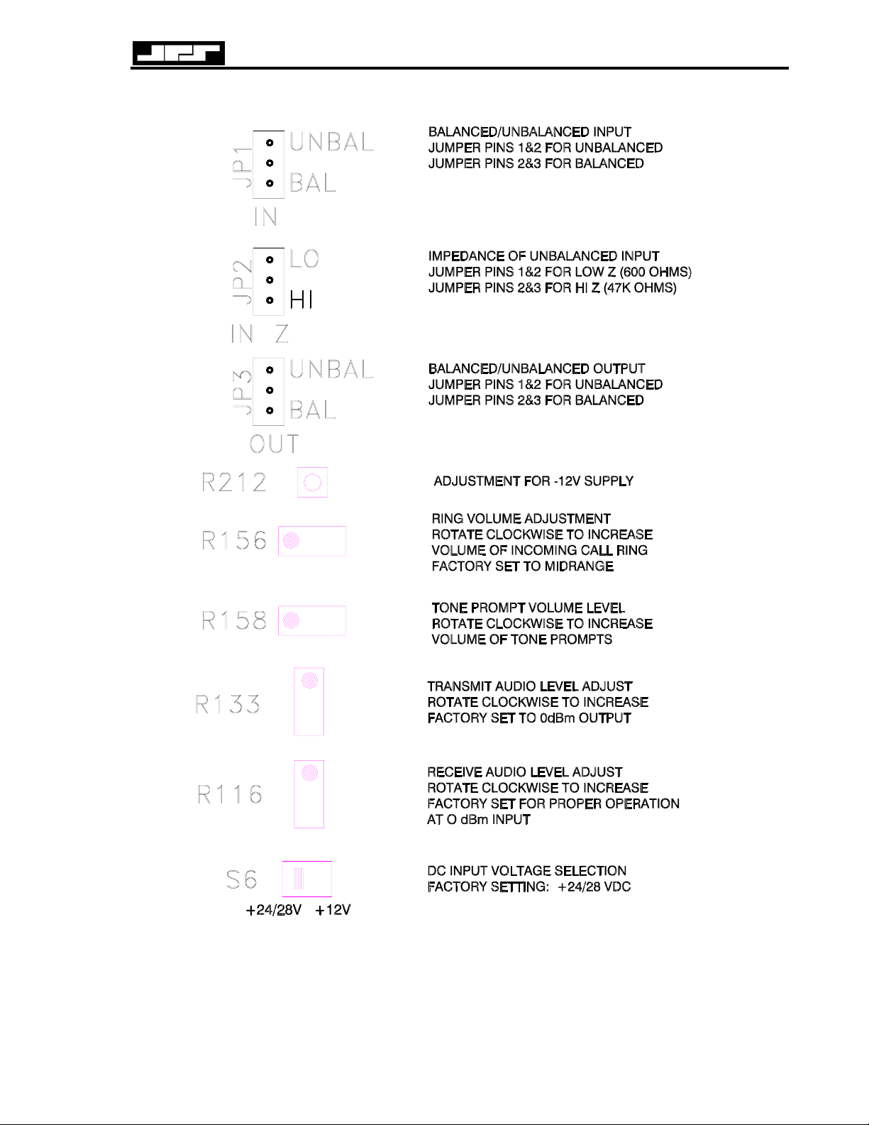
RTU-292 Operations Manual
Figure 2-4 Internal Option Setting Details
JPS Communications, Inc.
2-21
Page 38

RTU-292 Operations Manual
Figure 2-5 Audio Interface Wiring Diagram
JPS Communications, Inc.
2-22
Page 39

RTU-292 Operations Manual
Figure 2-6 Interface Details
JPS Communications, Inc.
2-23
Page 40

RTU-292 Operations Manual
2.11 INSTALLATION CHECKLIST
Table 2-20 Installation Checklist
Provide suitable Mounting and Cooling. See Section 2.5.
Check AC Line voltage selection. See Section 2.7.
DC Operation needed? See Section 2.7.
Make Interconnections. See Section 2.9 for External Interconnect Information.
Serial Remote Control needed? Set Serial Remote Baud Rate with SW1-1 and 2. See RS-
232 protocol in Section 5.
Set TX/RX Audio Levels if necessary. See Table 2-1 and Section 2.10.
Set Telephone Line Levels if necessary. See Table 2-1 and Section 2.8.
Are other Factory Default Settings correct for
this system?
See Table 2-1 and Table 3-2.
Make necessary changes as explained in sections 2.8, 2.10,
and 3.7
2.12 OPTIONS INSTALLATION AND CONFIGURATION
See section 7 for installation instructions for all field-installable options. Section 7 also
explains how to set-up any options that have configuration switches, jumpers, potentiometers,
etc. For any options not covered in section 7, refer to custom notes supplied with the RTU-292
or the option, or contact JPS for information.
End of Section 2
JPS Communications, Inc.
2-24
Page 41

RTU-292 Operations Manual
3 Operation
3.1 GENERAL
This section contains information and instructions required for proper operation of the RTU-
292.
3.2 FRONT PANEL CONTROLS, INDICATORS AND CONNECTORS
3.2.1 MAIN POWER SWITCH
The Main Power switch controls the external DC power to the unit. The switch is a locking
toggle type to prevent inadvertent operation.
3.2.2 HEADPHONE JACK
This front panel jack accepts a standard 1/4 inch diameter monaural phone plug. The output
will drive low, medium, or high impedance headphones. The phones audio level is adjustable
via the PHONES VOLUME control on the right side of the panel.
3.2.3 HANDSET JACK
This front panel jack is a standard 6-pin RJ12C jack that connects the handset to the unit.
3.2.4 HANDSET
The handset allows sending and monitoring audio to and from either the telephone line, the
radio, or both, depending on the HANDSET/PHONE and HANDSET/RADIO pushbutton
selections. The handset also has a PTT (Push-To-Talk) switch to key an associated radio. The
handset PTT switch is active only when any of the following functions are selected (associated
LEDs on): TEL LINE/RADIO, HANDSET/RADIO, or SPEAKER/RADIO. The PTT switch
need not be depressed when communicating with a second party via a PSTN line. The handset
earpiece audio level is controlled by the HANDSET volume control. A convenient hanger for
the handset may be attached to the left side of the front panel (mounting screws are installed in
the front panel, remove the nuts from these screws, throw the nuts away, and use the screws to
attach the hanger). This hanger, supplied in the RTU-292's accessory kit, may also be installed
elsewhere on the equipment rack.
3.2.5 SPEAKER
The speaker allows monitoring of telephone line and/or radio audio, depending on the
selections of the SPEAKER/PHONE and SPEAKER/RADIO monitor modes. In addition, the
speaker serves as the telephone ringer for incoming calls. The speaker volume (except for the
ring signal) is controlled by the SPEAKER volume control located on the right side of the front
panel. The ring signal may be enabled or disabled by the AUDIBLE RING pushbutton. The
ring volume is controlled by an internal potentiometer R156 (see section 2.8).
JPS Communications, Inc.
3-1
Page 42

RTU-292 Operations Manual
3.2.6 KEYPAD
The 12-key keypad is used for telephone dialing. It is active only when the TEL LINE/PHONE
path is selected. Dialing may be either via DTMF mode or pulse mode as determined by
internal dipswitch selection.
3.2.7 SPEAKER VOLUME CONTROL
This potentiometer controls the volume of audio (except telephone ringer volume) at the front
panel speaker. Rotate clockwise to raise audio from minimum to full. Telephone ringer
volume is controlled independently by an internal adjustment, R156 (see section 2.8).
3.2.8 PHONES VOLUME CONTROL
This potentiometer controls the signal level present at the front panel headphone jack and in the
handset earpiece. Rotate clockwise to increase the audio level.
3.2.9 TEL LINE BUTTONS
These three buttons, PHONE, RADIO and OFF, determine whether the internal telephone, the
radio, both, or neither (OFF) are connected to the telephone line.
Pushing the TEL LINE/PHONE button connects the RTU-292 internal telephone to the
telephone line and allows dialing using the keypad. Pushing this button will also answer an
incoming telephone call. The associated LED will be illuminated while the telephone line to
internal phone path is selected.
Pushing the TEL LINE/RADIO button connects the telephone line to the radio through the DSP
adaptive hybrid. The unit then starts its adaptation cycle by putting a burst of white noise onto
the telephone line. When the adaptation cycle is underway, the TEL LINE/RADIO LED will
flash. After successful completion of the adaptation cycle, this LED will be on continuously,
indicating that the unit is ready for operation.
The TEL LINE/OFF pushbutton will hang up any active TEL LINE/RADIO or TEL
LINE/PHONE connection.
3.2.10 HANDSET BUTTONS
These two buttons, PHONE and RADIO, allow the handset to be connected to the internal
telephone, the radio, or both simultaneously. Each button has an associated LED that is
illuminated when the path is active.
Pushing the HANDSET/PHONE button connects the handset to the telephone audio path ad
activates the handset microphone. Note that this will not take the telephone off-hook; the TEL
LINE/PHONE LED must also be on for the handset to be used to communicate over the
telephone line.
Pushing the HANDSET/RADIO button selects the handset to the radio audio path. When this
path is selected (HANDSET/RADIO LED is on) the handset PTT switch will key the radio
transmitter.
If both paths are simultaneously selected, the audio heard in the earpiece will be the radio
receive and telephone audio mixed together, and microphone input will be sent both to the
telephone line and to the radio transmitter.
JPS Communications, Inc.
3-2
Page 43

RTU-292 Operations Manual
3.2.11 SPEAKER BUTTONS
These two buttons, SPEAKER/PHONE and SPEAKER/RADIO, determine whether the
speaker monitors telephone receive audio, radio receive audio, or both. Note that if a radio-totelephone call is underway and both buttons are pressed, the full conversation is being
monitored. There is an LED alongside each button that is illuminated when the associated path
is selected.
3.2.12 TEL VOX
This button enables keying of the radio transmitter by the RTU-292 VOX (Voice Operated
Xmit) facility. When the VOX is selected (associated LED ON), the VOX is active, and the
key relay is energized when the VOX circuitry detects a signal from the telephone line. The
VOX PTT output has a “hang” time to keep it from dropping out during short pauses in speech.
The hang time duration is the length of time that the PTT signal will remain active following
the loss of detection of signal. (The hang time is internally adjustable; see section 2.8). If the
TEL LINE/RADIO LED continues to flash for more than ten seconds after the TEL
LINE/RADIO pushbutton has been pressed to make a connection, the unit has not adapted
properly and VOX operation will not be possible.
3.2.13 AUTO ANS BUTTON
This pushbutton may be used to manually enable (LED ON), or disable (LED OFF), the Auto
Answer feature. When enabled, the RTU-292 is in the Automated Operation Mode and the
unit will automatically answer the phone after 2 rings. See section 3.7 for a description of the
Automatic Operation capabilities of the RTU-292.
3.2.14 AUDIBLE RING BUTTON
This button determines if the ring from an incoming telephone call will be heard via the RTU292’s speaker. When the Audible Ring mode is enabled, the ring signal will be audible in the
speaker. The ring volume is independent of the SPEAKER VOLUME setting, and is set
internally by adjustment R156. Regardless of the position of the AUDIBLE RING button, the
LED indicator associated with the TEL LINE/PHONE button flashes on an incoming ring, so
that a visual indication of the ring signal (incoming call) is always provided.
3.2.15 KEY PUSHBUTTON
This pushbutton operates the key function of the RTU-292, sending a key command to the
associated transmitter. This button is functional at all times. The red KEYED LED next to the
KEY pushbutton is lit whenever a key command is sent to the transmitter from any source
within the RTU-292 (handset keyswitch, or TEL VOX, for example), not just from the KEY
pushbutton.
3.2.16 PEAK LED
This red LED flashes on audio peaks that are detected in the audio incoming from the receiver
to indicate the proper adjustment of the internal RX LEVEL control (R116). The input level is
correct when the PEAK LED flashes occasionally on incoming receiver speech peaks. If the
LED flashes continuously, the input level is too high and should be reduced (see paragraph
2.10). Note that this LED does not respond to telephone audio.
JPS Communications, Inc.
3-3
Page 44

RTU-292 Operations Manual
3.3 REAR PANEL CONNECTORS
Accessible at the RTU-292 rear panel are the radio connector, telephone line and local phone
connector, the signal terminal block, the DC power terminal block, an RS-232 connector, and
the AC power connector/voltage selector/fuse holder assembly. See section 2.9 for full pin-out
information.
3.3.1 P1 RADIO CONNECTOR
This male DB9 connector is the interface between a radio system and the RTU-292. It contains
transmit audio, receive audio, and keylines.
3.3.2 J1 TEL LINE
The RJ11C jack provides the telephone line connection to the RTU-292. The telephone line
connections are also available at the terminal block.
3.3.3 TERMINAL BLOCK
The terminal block is provided mainly as a convenience for the connection of the telephone line
to the unit if an RJ-11C plug is not available. This block also contains the key relay contacts to
the transmitter, remote key input signal, ground, and a spare External Signal Input.
3.3.4 J2 LOCAL PHONE CONNECTOR
This RJ-11C jack is used to connect a local phone to the unit. The Local Phone Option must be
installed for this port to be active.
3.3.5 P2 RS-232 CONNECTOR
This female DB-9 connector provides an interface between the RTU-292 and a radio or a
controlling terminal via standard RS-232 signal lines.
3.3.6 DC INPUT TERMINAL BLOCK
This two-position terminal strip has a pair of screw terminals, one for a ground wire and
another for the DC input of either +12 or +24/+28VDC (nominal). Internal slide switch S6 is
used to select between +12 and +24/+28 volt input. Refer to section 2.7.
3.3.7 P1 AC POWER CONNECTOR
This is a combination AC power connector, fuse holder and line voltage selector. It
incorporates a line filter to reduce the possibility of RF pickup by the power line from closeproximity transmitters. Section 2.7 has complete instructions for the line voltage selection and
fuse replacement.
JPS Communications, Inc.
3-4
Page 45

RTU-292 Operations Manual
3.4 OPERATION
3.4.1 OPERATION OVERVIEW
The RTU-292 is a flexible piece of equipment that contains a telephone and a radio/telephone
interface circuit with a unique adaptive hybrid. These circuits are arranged so that they can be
used together or independently in several different ways. The unit may be used to manually
create the telephone to radio connection, or an unmanned connection can be made in the
automated mode. Here are some examples of RTU-292 operating modes:
1. The telephone may be used to place and receive calls independently of the radio interface.
2. The speaker may be used to monitor radio traffic while the handset is used with the internal
telephone to place a telephone call.
3. The handset may be used to transmit/receive from the radio.
4. The radio may be connected to the phone line through the adaptive hybrid.
5. A phone call may be patched through to a radio link, or a radio link patched into a phone
line. This can be accomplished unattended using a pair of RTU-292s in the Automated
Mode.
The following paragraphs describe the RTU-292 operating modes in detail.
3.4.2 USE OF THE RTU-292 SPEAKER TO MONITOR AUDIO
1. To monitor radio receive audio, push the SPEAKER/RADIO button. The associated LED
will light.
2. To monitor telephone audio, push the SPEAKER/PHONE button. The associated LED will
light. Either the TEL LINE/PHONE or the TEL LINE/RADIO LED must be ON,
indicating that the telephone is off-hook, or there will be no audio present.
3. Note that radio receive audio and telephone audio may be simultaneously monitored.
3.4.3 PLACING A TELEPHONE CALL
1. Ensure that telephone audio will be available at the handset (HANDSET/PHONE LED is
ON).
2. Connect the RTU-292 to the outside phone line by pressing the TEL LINE/PHONE button;
listen for the dial tone.
3. When dial tone is heard, dial the desired number using the keypad. The handset will
function like an ordinary telephone handset.
4. If desired, the phone conversation may also be monitored via the front panel speaker by
depressing the SPEAKER/PHONE switch (SPEAKER/PHONE LED ON). Prevent
feedback by controlling speaker volume and keeping the handset a sufficient distance from
the speaker.
5. To hang up, press the TEL LINE/PHONE button, or the TEL-LINE OFF button, so that the
TEL LINE/PHONE LED goes out.
JPS Communications, Inc.
3-5
Page 46

RTU-292 Operations Manual
3.4.4 RECEIVING A TELEPHONE CALL
NOTE
The handset-to-telephone path may be left in the enabled condition
(HANDSET/PHONE LED ON) even when the unit is not connected to the
telephone line. Only one button (TEL LINE/PHONE) must then be pushed to
answer the telephone. The following scenario assumes that the
HANDSET/PHONE LED is already ON.
1. When the ring is heard (or the flashing TEL LINE/PHONE LED is observed) indicating an
incoming call, push the TEL LINE/PHONE button and speak into the handset. It isn't
necessary to press the handset PTT switch to use the telephone.
2. To hang up, press the TEL LINE/PHONE button again. The adjacent LED will turn off.
3.4.5 PUTTING A TELEPHONE CALL ON HOLD
Once a telephone call has been received or initiated and the TEL LINE/PHONE LED is
illuminated, pressing the HANDSET/PHONE button or the SPEAKER/PHONE button will put
the call on “hold”. (The call will not be cut off as long as the TEL LINE/PHONE button is not
pressed.)
For example, if the RTU-292 operator has made a telephone connection and wishes to contact a
radio party to continue setting up the patch, he may place the telephone call on “hold” and
speak with the radio party using the handset as described in 3.4.6.
3.4.6 USING THE HANDSET WITH THE RADIO
Pressing the HANDSET/RADIO button will connect the handset to the radio's audio lines
(associated LED will be on). The receive audio will be heard in the earpiece, and when the
radio is keyed (via the handset or front panel key switches) the handset mic audio will be
routed to the transmitter. The SPEAKER/RADIO pushbutton may also be used to monitor
radio receive audio via the RTU-292's front panel speaker.
3.4.7 CONNECTING THE RADIO TO THE TELEPHONE LINE
To patch the radio to the telephone line, push the TEL LINE/RADIO button to ON. This will
cause the adaptive hybrid to operate in the following manner:
3.4.7.1 Initial Adaptation
The two-wire to four-wire hybrid in the RTU-292 adapts to the phone line each time the TEL
LINE/RADIO button is engaged. To adapt, it measures the characteristics of the line by
placing a white noise source (built into the unit), on the line for a short time. While the noise
burst is connected, the amount of signal “reflected” from the phone line is measured and
adaptation begins. The adaptation algorithm adjusts the adaptive hybrid to minimize the
reflected signal, throughout the audio frequency spectrum, from the phone line. During the
adaptation process, the TEL LINE/RADIO LED will flash. When adaptation is complete, the
JPS Communications, Inc.
3-6
Page 47

RTU-292 Operations Manual
noise source is switched off, the LED is lit continuously, and the unit is ready for operation.
This adaptation procedure normally takes less than one second.
For adaptation to be successful, the far end of the phone line must be quiet (there must be no
signal coming into the RTU-292 from the phone line during adaptation). If there is incoming
audio, the unit may not be able to adapt, but will keep trying for up to ten seconds. For
example, the telephone user at the far end of the phone line should not talk during the
adaptation cycle. If the TEL LINE/RADIO LED does not stop flashing within the normal
second or two after the TEL LINE/RADIO button is pushed, wait a short time longer. If the
LED still continues to flash, chances are that there is excessive noise on the phone line, and it is
best to hang up and redial.
Because the adaptation algorithm is very robust, connection to an unquiet phone line is about
the only case where the RTU-292 will fail to adapt, as the hybrid has the ability to adapt to line
conditions from a short-circuit to an open-circuit, as well as the impedance presented by the
extremely complex distributed network of a telephone line.
3.4.7.2 CONTINUOUS ADAPTATION
Once the initial adaptation is complete and the unit begins operating, hybrid adaptation
proceeds continuously using receiver audio sent down the telephone line (the noise burst is not
needed again). This feature enables the RTU-292 to automatically adapt its hybrid balance to
changing line conditions.
3.4.8 MANUAL PHONE PATCH PROCEDURE
A telephone patch establishes a communications link between a distant radio, a local radio
(interfaced directly to the RTU-292 via the P1 Radio connector) and a distant telephone that is
connected to the unit via the telephone line. This distant telephone will be patched through the
local radio set to the distant radio set allowing communication directly between the distant
radio set and the distant telephone.
Begin with the RTU-292 installed and its power on:
3.4.8.1
The operator first establishes a link between the local radio set and the distant radio set using
the RTU-292’s handset with the radio, as described in paragraph 3.4.6. Alternatively, the
operator may have received a radio call from a distant radio party wishing to make a phone
patch.
Using the RTU-292’s internal telephone set, the operator now places a call to the distant
telephone.
Or
3.4.8.2
The operator begins the procedure by using the RTU-292’s internal telephone set to place a call
to the distant telephone party. Alternatively, The operator may have received a call from a
distant telephone party wishing to make a phone patch. He then places the telephone party on
hold while the distant radio party is contacted.
The operator then establishes a link between the local radio set and the distant radio set using
the RTU-292’s handset with the radio, as described in paragraph 3.4.6.
JPS Communications, Inc.
3-7
Page 48

RTU-292 Operations Manual
3.4.8.3
Once the telephone and radio party have both been contacted, the operator should advise the
telephone party that a phone patch is being set up. He may want to advise that a short noise
burst (not extremely loud) will be heard in the telephone receiver, and that the conversation can
proceed following the burst. The operator then pushes the TEL LINE/RADIO button to begin
adaptation, indicated by a flashing TEL LINE/RADIO LED.
3.4.8.4
After the RTU-292 automatically adapts itself to the phone line, and the TEL LINE/RADIO
LED will stop flashing and stay continuously illuminated. This indicates that a complete link
has been established between the distant radio set and the distant telephone, via the RTU-292
and the local radio set.
3.4.8.5
Progress of the call may be monitored via the speaker on the RTU-292 front using the
SPEAKER/PHONE and SPEAKER/RADIO buttons.
3.4.8.6
The call may also be monitored with the handset. The operator may speak and listen to either
the telephone party alone, the radio party alone, or both together, using the HANDSET
pushbuttons.
3.4.8.7
When the conversation is complete, the operator pushes the TEL LINE OFF button to
disconnect from the phone line. The TEL LINE/RADIO and TEL LINE/PHONE LEDs will
both turn off, indicating that the phone is back on-hook (disconnected).
3.4.9 TRANSMITTER KEYING, HALF DUPLEX SYSTEM
For a normal half-duplex radio link, it is usual for the VOX in the RTU-292 to key the
transmitter. The VOX responds to signals from the telephone line and operates the keying
circuits when voice is present. Once the VOX has tripped, it remains active for the selected
“hang time” following the loss of audio to prevent dropout on pauses between syllables. The
unit also incorporates a short delay of the transmitted audio, which allows the VOX to key the
transmitter a short time before the audio arrives, so that the RF output can be at full power to
avoid missing part of the first syllable.
The VOX in the RTU-292 is generated within the DSP and is extremely sensitive and reliable.
However, there are occasions when the audio level from the telephone line is too low to operate
the VOX reliably, or for some other reason it is desired to key the transmitter manually. To do
this, operate the front panel KEY pushbutton or the handset PTT button to key the transmitter.
The VOX switch can be left engaged, if desired, so that the operator can override the VOX at
any time, or the VOX may be disengaged, so all keying occurs manually.
JPS Communications, Inc.
3-8
Page 49

RTU-292 Operations Manual
3.4.10 TRANSMITTER KEYING, FULL DUPLEX SYSTEM
In a full duplex system, the transmitter can be held continuously keyed during a conversation,
because the system can receive and transmit at the same time. Thus, VOX is not required. In
this case, the transmitter may be keyed from the RTU-292 by pulling either of its external KEY
inputs low. The Full/Half Duplex dipswitch setting has no effect on transmitter keying.
3.5 REMOTE KEY
The RTU-292 contains a remote /Key signal that can be activated at any time. The unit will
key the transmitter any time this input is pulled low while the power is on.
3.6 SELF TEST
The RTU-292 self-test routine operates each time the unit is powered up. This routine tests the
non-volatile RAM for out-of-range parameters and various functions of the DSP module. The
unit also performs a "Walking LED" test, turning each of the front panel LEDs on in
succession, providing an indication of correct I/O operation. A successful self-test will be
indicated by the "Positive Acknowledge" tone prompt and, if the Voice Prompt Option is
enabled, the “RTU-292 Automatic Phone Patch” greeting prompt. Failure of the self test (or
failure of the DSP module at any time) is indicated by a long "Negative Acknowledge) tone and
a constantly blinking PEAK LED. The radio connect functions of the unit will not operate,
although the telephone may continue to operate.
3.7 AUTOMATED OPERATION
The RTU-292 can patch the telephone line to a radio system completely unattended when in the
Automated Operation Mode. To enter this mode, simply press the AUTO ANSWER
pushbutton. The unit will signal its present status and request remote operator responses
through the use of Tone Prompts and (if equipped) with actual voice messages called voice
prompts.
3.7.1 TONE PROMPTS
The RTU-292's tone prompt sequences and their meanings are:
3.7.1.1 Positive Acknowledge (ACK)
When the RTU-292 wants to signal an acknowledge it will play 1 short high-pitched tone
followed by 1 short low-pitched tone. The RTU-292 usually plays an ACK in response to a
user-initiated command. ACK means that the command was received and was legitimate
3.7.1.2 Negative Acknowledge (ERROR)
When the RTU-292 wants to signal a negative acknowledge or error it will play 1 long lowpitched tone. An ERROR is usually played as a response to incorrect user entry, or following
the receipt of an illegitimate command that could not be executed.
JPS Communications, Inc.
3-9
Page 50

RTU-292 Operations Manual
3.7.1.3 Waiting For Input (QUERY)
When the RTU-292 needs user input it will play 1 short low-pitched tone followed by 1 short
high pitched tone. A QUERY is played whenever the user needs to enter some data such as a
password or telephone number.
3.7.1.4 Radio Is Keyed (KEYED)
When the RTU-292 wants to signal that the user has keyed the radio it will play 1 short highpitched tone. The RTU-292 will play KEYED whenever the user has manually keyed the radio
by entering the correct telephone command.
3.7.1.5 Radio Is Unkeyed (UNKEYED)
When the RTU-292 wants to signal that the user has unkeyed the radio it will play 1 short lowpitched tone. The RTU-292 will play UNKEYED whenever the user has manually unkeyed the
radio by entering the UNKEY telephone command.
3.7.1.6 Disconnecting
(DISCONNECT)
When the RTU-292 wants to signal that it is dropping the radio communications link (and
hanging up the phone) it will play 3 short high-pitched tones. The RTU-292 may disconnect
for a number of reasons:
1. Any time the user enters a * (star) followed by a # (pound sign).
2. Whenever Busy Tones or Reorder tones are heard on the phone line. The DSP algorithms
are always searching for call progress activity on the phone line.
3. The unit will also disconnect if there is a lack of any activity on the phone line for a time
longer that that set by the Inactivity Timer (see Table 3-1). If the unit signals that it is
dropping the link due to a lack of activity, either party may prevent the disconnection by
speaking within five seconds.
4. Whenever “Line Reversal” (Reverse Battery Signaling) is detected on the phone line.
3.7.2 VOICE PROMPTS
If the RTU-292 is equipped with the Voice Prompt Option it will prompt the user for input and
signal its current status to the user status by playing pre-recorded messages, called voice
prompts. Tone prompts are played before each voice prompt. For example, if the RTU-292
wanted the user to enter the password it would play the QUERY tone sequence followed by the
voice prompt “
Enter Password”. The number of different tone prompts is limited because the
average user cannot be expected to remember more than a few. However, since voice prompts
are largely self-explanatory the RTU-292 has more than 30 different voice prompts. The
remainder of this section includes a description of the voice prompts that the unit provides at
appropriate times during unit operation. These prompts are only heard if the Voice Prompt
Option is installed.
3.7.3 CALLING THE RTU-292 VIA THE OUTSIDE LINE
If the RTU-292 is set for Automatic Answer (AUTO ANSWER LED lit) it will answer an
outside call after 2 rings. Once the unit answers the phone, the caller controls the unit by
sending commands via the keypad of a DTMF telephone. Rotary-style telephones cannot be
used to control the RTU-292.
JPS Communications, Inc.
3-10
Page 51

RTU-292 Operations Manual
The following paragraphs describe the sequence of operations used to automatically place a call
through the RTU-292 to a radio via the outside phone line. This description assumes that the
RTU-292 has a Voice Prompt Option installed. Units without a Voice Prompt Option will
function identically except for a lack of voice prompt messages. The tone prompts listed in
3.7.1 are provided by the RTU-292 whether or not the Voice Prompt Option is installed.
3.7.3.1 The Caller Dials The RTU-292
When a call is made over the telephone line by a distant telephone to the RTU-292, the unit
answers the phone and plays the greeting voice prompt: “RTU-292 Automatic Phone Patch”.
If password protection is enabled the unit plays the QUERY tones followed by the “
Password
” voice prompt. If password protection is not enabled the unit will move directly to
the adaptation process (3.7.3.3).
3.7.3.2 The Caller Enters The Password (if enabled)
The password is a sequence of numbers (0-9). The password may range from 1 digit up to 10
digits. When the RTU-292 is shipped from the factory it is given the default password “1 2 3
4”. The password may contain only numbers (no * or # characters). If the user enters an
incorrect password the RTU-292 will give him two additional tries. If the unit has the Voice
Prompt Option installed, voice prompts will guide the user in trying again to enter the correct
prompt. Otherwise, the “Query” prompt will be given. If the correct password is still not
entered after three tries, the unit will then play the DISCONNECT tones and immediately hang
up. When the unit receives the correct password, it moves on to the adaptation process. See
3.7.3.4 for instructions related to changing the existing password.
Enter
3.7.3.3 The RTU-292 Adapts To The Phone Line
The RTU-292 hardware has an Adaptive Hybrid that is controlled by a Digital Signal Processor
(DSP). The hybrid matches the RTU-292 to the telephone line and also allows the radio to be
keyed automatically by detecting the presence of the caller's voice on the telephone input. This
“Voice Operated Transmit” method of keying is called VOX. Note that the VOX will be
activated for any type of signal on the input, whether it is speech or any other energy above the
VOX sensitivity level.
Before the DSP can accurately detect the caller's voice the RTU-292 must first "adapt" to
current phone line conditions. During the adaptation process the DSP will momentarily emit
white noise on the phone line. This noise burst sounds like a loud hiss. It is important for
successful adaptation that the caller does not talk or enter any DTMF commands during the
adaptation process. It helps to keep the phone line as quiet as possible. The adaptation process
will normally take less than two seconds to complete, but under noisy line conditions the
process may take as long as 10 seconds. During the adaptation process, the DSP measures the
white noise that is reflected back from the phone line and matches the RTU-292 to minimize
the reflected signal. This process is completely automatic and requires no user adjustments.
After the DSP has adapted, the RTU-292 will play the ACK (acknowledge) tones and give the
“
Ready” voice prompt (if the Voice Prompt Option is installed). If the DSP cannot adapt, the
unit will play the ERROR tone and give a “
VOX Unavailable” voice prompt. If VOX is
unavailable the caller must give a “KEY” command before speaking, and then give an
“UNKEY” command turn off the transmitter and listen to the reply (see 3.7.3.4).
JPS Communications, Inc.
3-11
Page 52

RTU-292 Operations Manual
3.7.3.4 The RTU-292 Enters the COMMAND Mode
After the RTU-292 completes the adaptation sequence, it enters the Command Mode and waits
for the caller to respond with commands. In Command Mode the user may enter DTMF
commands by pressing a number on the telephone’s keypad. The unit stays in Command Mode
until the caller gives the * # sequence to hang up. If the caller gives an incorrect command the
unit plays the ERROR tone and gives the “
When the RTU-292 is used in the command mode, it is connected to a radio system that is
ready to respond to the basic RTU-292 commands. At a minimum, the radio must be turned on
and set to the appropriate frequencies, and the radio audio and PTT input lines must be
connected to the RTU-292. One of the dipswitches allows the RTU-292 to be put into the
Radio Control Mode via a DTMF command. This mode enables the RTU-292 to control a
companion Motorola URC-200 radio via its RS-232 serial port. See Tables 2-9, 3-1 and 3-3.
It is important to note that only the distant phone connected to the telephone line is
routed through the DSP and therefore it is the only phone that can use the RTU292's VOX function. The local phone and the unit's handset and keypad do not
have VOX capability. Operators using the local phone or the handset to
communicate via the radio must always disable the VOX function and manually
key and unkey the transmitter.
Invalid Entry” voice prompt.
NOTE
3.7.4 PLACING A CALL IN THE COMMAND MODE:
When a phone call is initiated by the RTU-292 to a distant phone on the outside line, and the
called party picks up the phone, the unit's DSP will immediately execute the adaptation process.
When it is successful, the RTU-292 responds with the “
could not adapt, the RTU-292 gives the “
VOX UNAVAILABLE" prompt, informing the recipient
READY” voice prompt. If the DSP
of the call that he must manually key and unkey the transmitter. All other operation procedures
are the same as when a call is initiated by the distant telephone to the RTU-292.
3.7.5 TERMINATING A CALL:
There are several different ways to terminate a call.
1. If the PSTN that the RTU-292 is connected to has “Reverse Battery Signaling” (sometimes
called “line reversal”), the call will be terminated whenever the telephone caller hangs up
the phone. Reverse Battery Signaling is used by most domestic US phone systems, but is
not widely used outside of the US. Reverse Battery Signaling momentarily inverts the tip
and ring lines to signal that a caller has gone back on-hook (hung-up).
2. The sequence * # will cause the system to disconnect. This sequence may be given at ANY
time, even when the system is prompting for input. If Reverse Battery Signaling is not
present, the * # termination sequence is always required at the distant phone, as the RTU292 will not be aware that the call has been terminated unless the unit receives Busy or
Reorder call progress tones. Otherwise the link will not be disconnected until the inactivity
timer expires (see table 3-1 for information about setting the inactivity timer duration). If
JPS Communications, Inc.
3-12
Page 53

RTU-292 Operations Manual
the unit signals that it is dropping the link due to a lack of activity, either party may prevent
the disconnection by speaking within five seconds.
3. Pressing the OFF button on the front panel of the RTU-292 will also cause the system to
disconnect.
4. When the local phone is used, its operator may use the * # sequence or may simply hang up
the phone.
3.7.6 DTMF CONTROL COMMANDS
Tables 3-1, 3-2, and 3-3 explain and list the RTU-292’s various DTMF command modes.
DTMF commands may be entered via a connected telephone, a telephone set when the Local
Phone Option is installed, or via the front panel keypad*. Additionally, the DTMF keypad on a
radio may be used to make connections (see DTMF Access Option, 3.7.11).
* Some restrictions apply when sending commands via the front panel keypad:
3.7.6.1 OPERATING THE RTU-292 FROM THE FRONT PANEL KEYPAD
The RTU-292 can be operated from its front panel to allow the unit to be programmed, and if
so equipped, control a Motorola URC-200 radio. When using the front panel, the operator uses
the handset and keypad.
To begin front panel operation the user must enter three "*" keypresses. The RTU-292 will
respond with an Acknowledge tone prompt and the voice prompt "READY". At this point all
front panel keypad entries are treated just as though the user were sending commands via the
telephone or local phone.
Front panel control operation will continue until one of the following conditions occurs:
• The user enters a "*#" sequence.
• There is no PTT activity or keypad activity for the duration of the activity timer.
While the operator is using the keypad to control the RTU-292, the unit will not be available
for:
• PSTN Auto Answering.
• Radio Squelch Break Access (S/W option).
• Radio DTMF Control (S/W option).
• Local Phone Control (H/W option).
JPS Communications, Inc.
3-13
Page 54

RTU-292 Operations Manual
Table 3-1 Standard DTMF Operational Commands
These commands may be entered by the RTU-292 front panel keypad, or by the keypad of a
connected telephone or by a telephone set wired to the Local Phone Option. See 3.7.6 for
special instructions regarding the use of the front panel keypad to send DTMF Commands.
DTMF Command Function
* # Terminate the call.
* 0 Manual Keying Toggle.
Press once to key; the next press will unkey, etc.
To prevent simultaneous use of VOX and Manual Keying, if VOX was
enabled when * 0 is first entered, it will be shut off.
* 1 VOX Toggle.
If VOX is on, * 1 will turn it off. If VOX is off, * 1 will turn it on.
* 2 VMR Toggle.
If VMR is on, * 2 will turn it off. If VMR is off, * 2 will turn it on.
VMM-100 Option must be installed
* 3 Noise Reduction Toggle.
If Noise Reduction is on, * 3 will turn it off. If it’s off, * 3 will turn it
on. VMM-100 Option must be installed.
* 4 Security Mode Toggle.
If Security Mode is on, * 4 will turn it off. If it’s off, * 4 will turn it on.
Security Device Option must be installed (not currently available).
* 5 Page the Operator (make a call to the RTU-292 operator at the front
panel keypad / handset).
* 6 Page the Local Phone Operator (this command can obviously made
only by a connected telephone and not by the Local Phone).
* 7 Reserved for future use.
* 8 Radio Control Mode. (Requires optional radio control S/W.)
Use this command to enter the Radio Control Mode (dipswitch SW1-3
must also be ON to enable this mode). This mode enables DTMF
control of a companion Motorola URC-200 radio. See Section 7.
If the RTU-292 is in the Radio Control Mode, * # will return it to
standard RS-232 control mode. See Table 7-6.
* 99 Enter the programming mode.
If passwords are enabled, the user will be prompted for the system
password and not allowed to enter the programming mode unless the
password is correctly entered. See Table 3-2.
JPS Communications, Inc.
3-14
Page 55

RTU-292 Operations Manual
Table 3-2 Programming Mode DTMF Commands
These commands may be entered by the RTU-292 front panel keypad*, or by the keypad of a
connected telephone or by a telephone set wired to the Local Phone Option. The unit must
be put into the programming mode by entering *99 before these commands can be executed.
*See 3.7.6 for special instructions regarding the use of the RTU-292 keypad.
DTMF Command Function
* 0 x Call Logging Enable/Disable. * 0 0 Disables Call Logging (factory
default is disabled). * 0 1 Enables Call Logging. See 3. 7.13.
* 1 x x x # Change the password to "xxx". Terminate entry with #.
Password may be up to 10 digits long. Factory default is 1 2 3 4.
* 2 x
* 3x
* 4xx Program Speed Dial Entry “xx”. See 3.7.10.
Program the inactivity disconnect timer based on value of "x".
See 3.7.8 for more information.
* 2 0 Disabled (not recommended see 3.7.8)
* 2 1 2 Minutes
* 2 2 5 Minutes (factory default)
* 2 3 10 Minutes
* 2 4 20 Minutes
* 2 5 30 Minutes
* 2 6 45 Minutes
* 2 7 60 Minutes
* 2 8 90 Minutes
* 2 9 120 Minutes
Program the Calling Timer based on the value of “x”.
The RTU-292 will attempt to place a call to a telephone until this timer
expires. See 3.7.8 for more complete information.
* 3 0 30 Seconds (factory default)
* 3 1 1 Minute
* 5 Review Speed Dial Entry “xx”.
* 6 x
* 7 & * 8 Reserved for future use.
* 9 Reserved for JPS Manufacturing
* # Leave Programming Mode
JPS Communications, Inc.
Select 2 wire or 4 wire operation based on the value of “x”. See 3.7.15
* 6 0 2 wire operation (factory default)
* 6 1 4 wire operation
* 6 # Query to learn current setting
3-15
Page 56

RTU-292 Operations Manual
3.7.7 RTU-292 PASSWORD PROTECTION
The password protection feature is enabled by a dipswitch setting (SW1-5, see Table 2-1).
When passwords are enabled, access to the system is denied unless a user enters the correct
password. The same password applies both to access via telephone and via a radio (if the
DTMF Radio Access feature is used). Users are given three tries to correctly enter the system
password before the RTU-292 terminates the call attempt and returns to its waiting state.
The system assists the user in entering the password by the use of Voice and Tone Prompts (if
the Voice Prompt Option is installed), or simply with Tone Prompts.
The factory default password is “1 2 3 4”, and this password can be changed to any DTMF or
numerical value up to 10 characters in length. To change the password, first enter the
programming mode by entering ‘* 9 9”. If passwords are currently enabled, it will be
necessary to enter the correct password to continue programming. From the programming
mode, enter “* 1 x x x #” where “x x x” is the new password, up to 10 characters long. Next
enter “* #” to leave the programming mode.
3.7.8 INACTIVITY DISCONNECT TIMER
The inactivity disconnect timer ensures that the system does not remain locked up on a
completed call if system users forget to or are unable to terminate a call by normal means. The
inactivity timer samples audio from both the radio and the telephone. If no activity is detected
for a time equal to the Inactivity Disconnect Timer setting, the RTU-292 will notify the users
by three short beeps that they have five seconds to respond or the call will be terminated. If
either the radio user or the PSTN caller initiates activity within 5 seconds of the warning beeps,
the timer is reset.
Inactivity Disconnect Timer lengths of 2 minutes to 120 minutes (or disabled) are available.
Enter “* 9 9” to enter the programming mode, then “* 2 x” to set the timer. The value of x sets
the timer length. See Table 3-2 for the list of timer durations. The value of x = 0 will disable
the timer so that the connection may be maintained indefinitely. Unless a permanent
connection is required, disabling the timer is not recommended. If the telephone caller does not
correctly terminate the call, the unit can become locked up in the connected state. Once the
desired timer length is set, enter “* #” to leave the programming mode.
3.7.9 CALLING TIMER
The Calling Timer determines how long the RTU-292 will attempt to place a telephone call.
Once the timer expires, the RTU-292 terminates the attempt. Note that if the unit detects a
busy signal or other feedback that indicates that the call cannot be placed, the attempt will be
immediately terminated.
Two Calling Timer lengths, either 30 seconds or 1 minute, are available. Enter “* 9 9” to enter
the programming mode, then “* 3 x” to set the timer. The value of x sets the Calling Timer
duration. “* 3 0” sets the Calling Timer to the factory default length of 30 seconds. “* 3 1”
sets the timer to 1 minute. Once the desired timer length is set, enter “* #” to leave the
programming mode.
JPS Communications, Inc.
3-16
Page 57

RTU-292 Operations Manual
3.7.10 USING THE RTU-292 SPEED DIAL FEATURE
The RTU-292 has the ability of storing 99 telephone numbers in non-volatile memory. These
numbers may be used when making a call using via UHF/VHF radio with a DTMF keypad. To
use the speed dial feature, simply enter the speed dial number instead of a telephone number.
Note: The Voice Prompt Option is recommended if the speed dial feature is used, but is not
required. Voice prompts are essential in assisting the user in programming, reviewing, and
using the speed dial feature.
3.7.10.1 Programming the Speed Dial Directory
These numbers are programmed by first putting the RTU-292 into the programming mode. To
enter this mode, enter the DTMF command “
“READY” prompt.
1. The user next enters the command “* 4” on the keypad of the RTU-292*, the Local Phone
telephone set or the keypad of a connected telephone.
*See 3.7.6 for special instructions if the front panel keypad is used.
2. The RTU-292 gives the prompt “
3. The user enters two digits for the speed dial location. A leading 0 is used for locations 1-9.
For example, when the user is programming speed dial location number 1, he must enter
“01”.
4. The RTU-292 gives the prompt “
5. The user enters the digits of the phone number. When complete the user enters a “#”
6. The user may review the contents of the speed dial directory by entering the command
“
* 5”.
7. When programming is complete, enter the “* #” sequence to take the RTU-292 out of
programming mode.
3.7.10.2 Using the Speed Dial Feature
Operation is the same as standard, except when queried for a phone number by the RTU-292,
the radio enters the speed dial location instead of the telephone number. For example to call
the number stored at speed dial location six, the user enters * 0 6 # (star zero six pound). All
single digit speed dial numbers must be proceeded by a zero as in example provided.
ENTER SPEED DIAL LOCATION”.
ENTER PHONE NUMBER”.
* 9 9”. The RTU-292 will respond with its
.
JPS Communications, Inc.
3-17
Page 58

RTU-292 Operations Manual
3.7.11 OPTIONAL 4 WIRE OPERATION
The unit can be set to operate with a four wire device instead of a standard 2 wire phone. The
additional I/O is handled by header J6 on the main PCB. The STU-III option makes use of this
capability. To put the RTU-292, first place the unit in programming mode with the *99
command. Then enter the * 6 1 DTMF command. To return to 2 wire operation, enter * 6 0.
To query the unit for its current setting, enter * 6 # (requires voice prompt option to hear
response from unit). See Table 3-2. When programming is complete, enter * # to exit the
programming mode.
3.8 FACTORY RESET
It’s possible to perform a Factory Reset that will return all user-programmable parameters
(other than the speed dial directory) to the initial factory default settings. This includes the
system password, the Inactivity Disconnect and Calling Timers, etc.
To perform a Factory Reset, hold the 0 (zero) key in on the front panel keypad while the main
power is turned on. After the unit has powered up, let go of the 0 key.
3.9 SPEED DIAL RESET
A Speed Dial Reset completely erases the information in the speed dial directory.
To perform a Speed Dial Reset, hold the 1 (one) key in on the front panel keypad while the
main power is turned on. After the unit has powered up, let go of the 1 key.
JPS Communications, Inc.
3-18
Page 59

RTU-292 Operations Manual
4 RTU-292 Theory Of Operation
4.1 GENERAL
This section gives enough detail of the theory of operation of the RTU-292 audio and power
supply sections to allow them to be troubleshot in the field. The same level of detail is not
supplied for the DSP module and the CPU portion as they are considered impractical to field
troubleshoot because of the specialized knowledge and test equipment required. If a fault is
suspected in these sections, factory repair is required.
4.2 FRONT PANEL BUTTONS AND INDICATORS
Figure 8-1 is a schematic of the RTU-292 front panel. The control pushbuttons and associated
LEDs are arranged in three separate PC board assemblies: the Tel Line Switch Assembly, the
Handset Switch Assembly, and the Speaker Switch Assembly. Signals from each of these
assemblies are combined into one ribbon cable that plugs into the Main Board at J3. Each
control pushbutton switches +5V onto its control line when ON and open circuit when OFF.
Pulldown resistors on each of the control inputs pull the line to ground when its button is OFF.
The buttons are read by the processor on the Main Board. The processor, not the pushbuttons,
controls the unit’s audio gates as well as the front panel LEDs.
4.3 MAIN BOARD
Main Board Circuitry is detailed in Figure 8-2.
4.3.1 AUDIO BUS ARRANGEMENT
The audio switching is bus oriented. Each major bus is named after the output signal that it
carries for distribution with the major buses as follows:
Signal
Name
Source Comment
TEL U8C-11 Telephone Receive Signal.
MIC U15B-7 Amplified/AGC’d Microphone Signal.
RXA U22D-6 Amplified Radio Receiver Signal.
RING U33A-2 Telephone Ringer Signal.
DTMF J13-32 DTMF Dialer Output.
The bus signals are each gain-leveled to a nominal 0 dBm (0.775V rms) average amplitude,
except for the hybrid in/out signals, which are usually at a –12 dBm (0.194V rms). The bus
signals are routed to various destinations through analog gates controlled by signals from the
CPU on the Main Board.
JPS Communications, Inc.
4-19
Page 60

RTU-292 Operations Manual
4.3.2 TELEPHONE INTERFACE CIRCUITS
4.3.2.1 Telephone Send Circuits
Amplifier U1B generates the Telephone Send signal (the audio which is sent down the phone
line from the RTU-292). U1B is configured as an inverting stage with its gain set by a
combination of input and feedback resistors selected by analog gates U4A through U4D. The
send level calibration assumes that there is a 0 dBm signal level at the input to U1B on U8B-
15. (If the setup is done properly, this is assured by the PEAK LED, which is set to flash at a
peak level equivalent to 0 dBm.) The calibration is such that when a 600 Ohm load is placed
on the telephone line terminals, the signal level at TP3 will be 3 dB lower than stated send
signal level. This 3 dB margin allows some headroom for peaks in the program material
without overdriving the phone line.
Resistor R1 establishes the output impedance of the telephone send amplifier, and (in parallel
with R11) determines also the terminating impedance for the phone line.
Zener diodes CR2 and CR3 protect the circuitry in the RTU-292 from high voltage spikes on
the phone line. 1:1 Audio transformer T1 couples the RTU-292 to the phone line. Capacitor
C1 compensates the leakage inductance of the transformer to produce a flat frequency response.
Capacitor C2 keeps the phone line DC current out of T1. Instead of using the secondary of T1
to sink the phone line DC holding current, an active constant current load is used which
consists of CR1, Q1 and Q2 and associated components.
The constant current load provides a means of sinking the DC holding current from the phone
line so that the RTU-292 will seize and hold the line. Bridge CR1 corrects the DC polarity so
that a positive voltage is always applied to the collector of Q1, eliminating the need to be
concerned about the polarity of the phone line. Transistors Q1 and Q2 are connected as a
constant current load and C3 insures that the load does not respond to audio frequencies, so that
the load appears as a very high AC impedance in parallel with the transformer secondary.
When the load is in operation, the DC voltage from TP1 to TP2 will be approximately 4V to
8V.
The phone line connections are made via J1 or the terminal block J12 to relay K1, which, when
the power is off or the unit is in Disconnect, disconnects the phone line from the internal
circuitry. Components L1, L2 and associated capacitors form Pi-Section filters to remove RF
from the normally unshielded phone lines. RV1 is a metal-oxide varistor that limits high
voltage transients that might appear on the telephone line.
4.3.2.2 Telephone Receive Circuits
Amplifier U2A is the telephone receive amplifier, which is arranged as a non inverting stage
and gets its input via R11 from transformer T1. U2B is gain adjustable via a combination of
input and feedback resistors selected by analog gates U6A - U6D. The gain distribution is set
so that, with a 600 Ohm load on the telephone line terminals, the PSTN level stated in the Input
Signal Level Table will produce a -12 dBm signal at U2B-7.
Note that the telephone send signal appears mixed with the telephone receive signal at U2A-1.
Furthermore, the amount of send signal mixed in depends on the telephone line impedance, and
is also frequency dependent. It is the job of the DSP hybrid to remove the telephone send signal
and pass only the telephone receive signal to the transmitter output circuits. The inputs to the
adaptive hybrid are A/D 2 (U1A-1) and A/D 1 (U2B-7). The DSP hybrid essentially subtracts
JPS Communications, Inc.
4-20
Page 61

RTU-292 Operations Manual
the signal at A/D 2 from that at A/D 1 and the difference appears on D/A 1, which is named
TEL after passing through gate U8C.
4.3.2.3 Ring Detector and Tone Ringer
Integrated circuit U7 is an optocoupler that senses the ring voltage on the telephone line. When
a ring voltage is detected, U7-5 goes low with the frequency and cadence of the ring voltage.
This signal is fed to the DSP module on J14-28, where the DSP strips off the ring frequency
and passes the a signal with the ring cadence alone on J14-7 to the ring tone generator circuit.
Circuits U31 and U32 form a tone ringer to provide the audible ring signal for the RTU-292’s
speaker. U32 is a 10 Hz oscillator which frequency-modulates oscillator U31 via R41.
Because of the modulation by U32, U31 switches between about 1000 Hz and 800 Hz at a 10
Hz rate, producing a “warble” tone. Normally, both oscillators are held reset by J14-7. When
ring voltage is detected, J14-7 goes high, allowing the oscillators to run.
4.3.3 RADIO INTERFACE CIRCUITS
4.3.3.1 Receiver Input Amplifier
The input from a receiver is connected to P1-1 and P1-6. Jumper JP1 selects whether the input
is balanced or unbalanced. In Balanced position, the signal is fed to the primary of transformer
T2. In unbalanced position, the signal is fed to U20A through R110 and R111, which provides
a unity gain, AC-coupled input of 47k impedance. R110 and C59 are in the circuit for RF
decoupling. The secondary of T2 is connected to amplifier U20A, configured as a high input
impedance unity gain amplifier. In balanced position, Jumper JP2 determines the input
impedance of the receiver input. In low impedance position, R112 is placed across the
secondary of T2 to make a 600 ohm termination. In high input impedance position, R112 is
removed from the circuit, leaving only the 47k Ohm resistor R113. The output of U20A is fed
to amplifier U20B, a gain adjustable amplifier which sets the receiver input signal level. The
output of U20B is nominally at the level of -10dBm, and the adjustment range of R116 allows 10 dBm to be produced at U20B-7 with input signals in the range of -40dBm to +10dBm.
4.3.3.2 Transmitter Audio Output
Gain-adjustable amplifier U21A provides the audio output to the transmitter. The adjustment
range of R133 is set so that with 0 dBm audio at U21B-7, the signal on the secondary of T3
(loaded with 600 Ohms) can be adjusted between +10dBm and -40 dBm. Amplifier U21A gets
its input signal from mixer amplifier U21B, which is fed by analog gates U22A, B, C and
U23A and U23B. These gates route prompt, DTMF, microphone and telephone input signals
to the transmitter output.
4.3.3.3 Keying Circuits
The key relay, K2, provides two isolated outputs. Signals /Key Out and KB are the normally
open contacts of both halves of K2. These signals are routed to P1-4 and P1-9 and are shorted
to ground when the key relay is energized.
Signals from /KEY IN and CPU KEY are summed in U24B and drive key relay driver Q4.
Transistor Q5 is driven by the VOX key output from the DSP. U24A ensures that the
microphone key switch will not function unless enabled by the CPU board with the MIC KEY
EN signal.
JPS Communications, Inc.
4-21
Page 62

RTU-292 Operations Manual
4.3.3.4 DTMF Detector
Circuit U25 is a DTMF detector/decoder dedicated to listening for DTMF signals from the
radio. Its input is connected to the leveled radio receive signal at U20B-7. The DTMF data is
read by the processor. A separate DTMF detector running in DSP software listens for DTMF
from the telephone line.
4.3.3.5 FSK Modem
Circuit U26 is a hardware FSK modem that listens for FSK signals from the radio at U20B-7,
and can send FSK signals to the radio from U26-17.
4.3.4 HANDSET/ SPEAKER INTERFACE
4.3.4.1 Microphone Circuit
The handset is connected to J7, with the mic signal appearing on J7-5. Resistors R50 and R51
provide bias current for the electret or carbon microphone element (electret is standard).
Components L3, C20 and L4, C23 provide filtering against conducted RF. Amplifier U13A is
the microphone preamplifier; its output U13A-1 drives the ALC circuit composed of U14A and
U13B. The ALC holds the output level at U13B-7 to about -9dBm over a 30 dB input range.
Amplifier U15B boosts the mic signal level to about 0dBm to drive the MIC bus. Resistor R64
feeds some of the mic signal into the handset earpiece as “sidetone”, so the earpiece doesn’t
sound dead.
4.3.4.2 Speaker and Headphone Circuits
The signals that drive the speaker are selected by analog gates U18A, U18B, and U18C; and
are mixed in amplifier U16A. The output on U16A-1 is fed to the top end of the speaker
volume potentiometer on the front panel. The wiper of the volume pot is fed to the speaker
driver U17 through R89. The ring signal from the tone ringer is mixed via R88 so that it
bypasses the volume pot. (Its amplitude is set separately by R156).
Headphones and handset signals are selected by analog gates U19A, U19B, and U19C; and
mixed in amplifier U16B. Output U16B-7 is applied to the top end of the headphones volume
pot on the front panel. The signal from the pot wiper is fed to amplifier U15A through R65.
The output of U15A drives the handset earpiece through R67 and the headphone jack through
R68.
4.3.5 DSP MODULE
The DSP hardware circuitry is detailed in Figure 8-3. The general purpose of the DSP
hardware is to convert analog signals to the digital domain, operate on and manipulate these
signals digitally using the DSP chip, then convert the result back to analog. In this way, it is
possible to implement functions such as the adaptive hybrid, which would be impossible or
impractical to implement using purely analog techniques. In addition to the DSP chip itself, the
module contains two analog interface chips, static RAM for audio storage and delay, and a
program flash memory chip.
4.3.6 DSP SOFTWARE
The DSP software is contained in a FLASH memory chip located on the DSP module. All of
the following functions are implemented in software by the DSP
JPS Communications, Inc.
4-22
Page 63

RTU-292 Operations Manual
4.3.6.1 Adaptive Hybrid
The adaptive hybrid is the central function of the RTU-292. Its purpose is to separate and
isolate the telephone receive signal by subtracting the telephone send signal from the mixed
telephone send and receive signals. If this subtraction is done perfectly, the telephone receive
signal is completely isolated. The digital adaptive hybrid in the RTU-292, while not achieving
perfection, comes close, and gives as much as 40 dB isolation when measured with a
broadband noise source. Comparable isolation for a conventional hybrid would likely be only
10 dB, measured in the same way.
The adaptive hybrid samples the telephone send signal at A/D 2, samples the mixed telephone
send and receive signals on A/D 1, and outputs the isolated telephone receive signal to the
transmitter output amplifier on D/A 1.
The hybrid function also contains a threshold detector that allows VOX operation when balance
has been achieved.
4.3.6.2 Noise Generator
A pseudo-random noise generator is implemented to speed hybrid adaptation. During the
adaptation cycle, the input receiver audio is switched off by gate U8C, and the noise generator
switched on at gate U8A. The wide bandwidth of the noise assures that the hybrid is adapted
over the full audio bandwidth.
4.3.6.3 Peak Detector
A peak detector monitors the receive audio bus and signals at A/D 2 to flash the PEAK LED on
audio peaks which exceed 0 dBm. This function aids in setting up the RTU-292 with the
proper audio levels.
4.3.6.4 VOX
A VOX (Voice Operated Xmit) function looks at the output of the adaptive hybrid and triggers
if the audio exceeds a preset level. Once triggered, it stays active for a short time to prevent
VOX drop out on pauses between syllables. This is called Hang Time, and is adjustable via
Option Switch SW2-6. The VOX sensitivity is adjustable via Option Switches SW2-4 and
SW2-5.
4.3.6.5 Audio Delay
The output of the adaptive hybrid is delayed before being output to the transmitter output
amplifier. The purpose of the delay is to insure that the transmitter is keyed a sufficient time
before the audio arrives so that the entire first speech syllable is transmitted.
4.3.6.6 DTMF Detector
A DTMF detector is implemented in DSP software that listens to the telephone line signal after
the hybrid.
4.3.6.7 DTMF Generator
A DTMF generator is implemented in DSP software that outputs DTMF digits to the telephone
line for dialing. The output is from J13-32 DTMF, which is routed to gate U9D so it may be
mixed with the signal to be sent to the telephone line in U1A.
JPS Communications, Inc.
4-23
Page 64

RTU-292 Operations Manual
4.3.7 POWER SUPPLY
The power supply is detailed in page 8 of 9, Figure 8-2. It supplies regulated DC voltages of
+5V, +12V, -5V, and -12V from both AC and DC inputs.
4.3.7.1 AC Power Supply
The AC power supply is a conventional passive regulator supply with a small PC mounted line
transformer, T4 which has dual primaries for 115 or 230 VAC operation, and has dual 15 VAC
secondaries which are wired in parallel. T4 and bridge CR36 along with capacitors C120 and
C121 are configured as a positive full wave circuit supplying unregulated +BUS voltage (about
20VDC) to the +12V and two +5V regulators. One +5V regulator, U72, feeds the RTU-292
standard circuits. The other regulator, U71, feeds only the assemblies on the option tray. The
positive regulators are standard three-terminal types, using a finned heatsink for cooling.
The negative voltage is supplied by switching regulator U73, which converts the +BUS voltage
to -12V adjustable by R212.
4.3.7.2 DC Power Supply
The DC power supply allows the RTU-292 to be powered from either a +12V or +24V DC
source as well as the standard AC supply line input. Slide switch S6 configures the supply for
either +12V or +24/28V operation. This circuitry is reverse-polarity protected by schottky
diodes in series with the voltage lines.
If sufficient AC and DC power are simultaneously applied, the unit will draw power from the
AC line only. Its auto take-over feature will draw DC power only if the AC line sags.
The DC supply input is filtered by choke L2 and by capacitors C50 and C51. If the DC input is
+12V, this filtered supply feeds the +BUS directly via CR34, and supplies +12V around U70
via CR33. It also supplies voltage directly to the inputs of the +5V regulators through CR39
and R213, and through CR40 and R214. If the DC input is +24/28V, the +BUS is fed through
emitter follower Q24, which keeps the bus voltage from rising above about +24V when input
voltages of 24V to 32V are used.
4.3.8 CPU
The CPU portion of the main board controls all functions of the RTU-292. This board uses the
front panel switches and keypad, as well as the RS-232 serial communications port and signals
received over the telephone as control inputs. The Main board lights front panel LEDs to
display its current status, and controls the audio gates on the audio portion of the main board to
route signals to their correct destinations. Refer to pages 5, 6 & 7 of Figure 8-2.
The RTU-292 is controlled by microprocessor U46. The program that runs U46 resides in
EPROM U40. The unit’s current status is stored in EEPROM U41. Octal latch U39 creates
address lines A0 through A7 from the data bus and the AS control line. Voltage supervisor
U45 ensures that the microprocessor turns off and on in an orderly manner when power is
turned off and on or during power glitches. RS-232 driver U37 interfaces the microprocessor
with the serial communications port. The /IRQ (interrupt request) signal generated by portions
of U47 and U48 informs the processor when the keypad is under use or a DTMF signal has
been detected by the Audio Board.
Most of the rest of the circuitry comprises I/O devices. U43 and U44 create the chip selects
required to control these devices. U38 sends commands to the optional Voice Prompt Board.
JPS Communications, Inc.
4-24
Page 65

RTU-292 Operations Manual
Bus drivers U60 and U61 are the input devices for the front panel switches; latches U62 and
U63 light the front panel LEDs. Latches U50 through U53 send control signals mainly to the
audio circuit sections. U56 and U57 send inputs to the data bus; U54 and U55 read Option
switches SW1 and SW2. Keypad decoder chip U59 provides the keyboard interrupt and
translates keypad closures before sending them onto the data bus via latch U58.
4.3.9 PROMPT TONE GENERATOR
Timer IC U30 can create tones of 500, 600, 750 or 1kHz, depending on the states of control
signals from the CPU Board DT0 and DT1. The volume of these prompts may be adjusted via
potentiometer R158. U33B, U33C, and U33D route either tone prompt or voice prompt signals
to the circuitry; controlled by the T/V signal from the CPU.
4.4 OPTION INTERFACE BOARD
This board contains the basic databus, power audio, and control lines to operate the various
options that may be installed on the unit on the options tray. See figure 8-4.
4.5 VOICE PROMPT OPTION
The Voice Prompt Option outputs prerecorded voice prompts into the telephone send signal or
into the radio transmit audio output from the RTU-292. See figure 8-5.
4.5.1 SPEECH PROCESSOR
The heart of the voice prompt option board is the speech processor chip, U7. This chip is an
ADPCM (Adaptive Pulse Code Modulation) processor containing built-in A/D and D/A, and
can be used for recording as well as playback. The digitized voice prompts are contained in
EPROM U5, which U7 accesses via data bus AD. The prompt analog audio is output on U7-28
and is passed through amplifiers U9 and U10. These amplifiers are arranged as a five-pole
active low-pass filter which removes remnants of the 8 kHz sampling frequency from the
output audio.
4.5.2 CONTROL PROCESSOR
The control microprocessor is the 68HC11A0, an 8-bit processor running at 8 MHz with a basic
instruction cycle time of 2 microseconds. There is some I/O from the processor chip itself from
Port D (pins 20 to 25) and Port A (pins 27 to 34) which controls the Audio Processor chip. The
control input to the board is to Port E (Pins 43 to 50) from connector J1. The lower eight bits
of the address bus are separated from the data bus by address latch U2.
EPROM U4 is the program memory, a 27C256 providing 16k of address space.
Chip select signals for the various I/O are provided by PEEL U6.
Several devices on the CPU board use a 3.58 MHz clock signal that is provided by crystal Y2
and gates U12B and U12C.
U3 is a reset generator that ensures an orderly power-up sequence for the microprocessor and
associated components. It senses the voltage on the +5V line and generates a reset while the
voltage is below approximately 4.55V. As the voltage rises above the threshold, a delay is
generated by C4 to insure processor clock stability before operation commences. Resistor R5
prevents resetting on short spikes on the 5V line.
JPS Communications, Inc.
4-25
Page 66

RTU-292 Operations Manual
4.5.3 VOICE PROMPT SOFTWARE
The voice prompt board software receives the prompt number command through J1 and
translates it into the prompt address in EPROM U5.
4.6 LOCAL PHONE OPTION
The Local Phone Option allows a standard telephone set to be plugged into an RJ-11C modular
jack at the rear of the RTU-292. This telephone set may then be used to place or receive calls
via the RTU-292 to the PSTN or an associated radio. The Local Phone Option can also be used
to control the RTU-292 remotely, changing various configuration options (see section 3.7).
4.6.1 INTERFACE CIRCUITRY
Amplifier U3A generates the local telephone send signal. This mixing amplifier accepts inputs
from the dial/busy generators U5 and U6, and from the local phone send line. This line from
the audio board, may be the audio from the telephone lines, prompt tones, receiver audio,
sidetone audio or DTMF tones, depending on the state of control gates on the audio board. The
gain is set to produce an approx. -9 dBm level at U3A-1. U3B is configured as a conventional
active hybrid. The local phone send signal is sent to U3B via R8 and R35. The combination
send plus receive signal reaches U3B via R7. The send signal is subtracted from the send plus
receive signal, leaving only the receive signal at the output of U3B.
4.6.2 DIAL/BUSY GENERATORS
Dial/Busy signals are composed of two tones, so a pair of frequency sources, U5 and U6, are
required. Each of these 555 timer ICs provides a square wave output. R30 and C10 set the
frequency of U5 to 460 Hz. The frequency of U6 is 620 Hz when Q2 is off, set by R24 and
C11. When commanded by the CPU Board, Q2 turns on, placing C12 in parallel with C11.
This cuts the frequency of U6 to 350 Hz.
The CPU Board normally holds the timers off, but when a high signal is sent on the DTONE
line, U5 and U6 turn on. Their square wave outputs are smoothed by the RC filter networks
made up of R31, R34, and C18 and R32, R33, and C17.
4.6.3 LOCAL TELEPHONE LINE INTERFACE
Tip and Ring signals are brought to the board on J1. Varistor RV1 limits transients that may
appear on the local phone line. The silent ring trip circuit will sense a voltage drop across R22
if the local phone is taken offhook while it is not ringing (K1 will be in the non-energized state
shown in the schematic). This voltage drop will turn on Q5, which signals the offhook
condition to the CPU board via J1-5.
The local phone is made to ring by the CPU Board when it J1-9 is brought high, turning on Q1
and energizing K1. K1 switches the ring generator U4 onto the telephone line. The ring
cadence is controlled by the CPU Board via the RING signal at J1-2. If the telephone goes
offhook during the ring cycle, the voltage drop across R18 turns on Q3, pulling J1-5 high.
Diodes CR1 and CR2 provide transient suppression for the audio circuitry.
JPS Communications, Inc.
4-26
Page 67

RTU-292 Operations Manual
5 Remote Control Protocol
5.1 GENERAL
Included in this section are instructions for controlling the RTU-292 via its RS-232 serial
communications port. The protocol listed in this section is the standard command set that
accompanies the standard software version. If an RTU-292 is shipped with custom software
that employs different commands, a set of special version notes, including a modified protocol,
will be shipped with the unit.
5.2
RS-232 REMOTE CONTROL OVERVIEW
The RTU-292 may be controlled and monitored remotely via its RS-232 interface. The RS-232
interface consists of RX, TX and Ground only. Hardware and software handshaking are not
used. The serial format is 8 data bits, 1 stop bit, and no parity. The baud rate is controlled
by setting DIP switches on the CPU card. Available baud rates are 300, 1200, 2400 and 9600.
All commands to the RTU-292 and responses sent from the RTU-292 use standard ASCII
characters. All remote commands are terminated with a carriage return (CR) and (optionally) a
line feed (LF). Status information returned from the RTU-292 will always be preceded by a
"%" character, and is also terminated by a CR. This protocol allows control and monitoring of
the RTU-292 via a dumb terminal or a computer program. The commands issued to the RTU292 are not case sensitive.
5.3 COMMANDS SENT TO THE RTU-292
The following section describes the operation of each of the RTU-292 remote control
commands. All commands have the format:
cmd <data> <data> ... <data> <CR>
The first string is the command string. The command string must not be preceded by any
space characters. There is at least one blank (space) character after the command string. Any
data that is required by the command follows next. Multiple data sections are delimited by at
least one space. Most commands require that data be presented in a specific order. Finally
the command is terminated by a Carriage Return character (CR). Line feed characters may be
included after the Carriage Return, but they are not necessary.
Examples:
Turn on the Speaker-Radio audio:
SPKR_RAD ON <CR>
Get the firmware revision number:
VER <CR>
JPS Communications, Inc.
5-1
Page 68

RTU-292 Operations Manual
When a command is sent to the RTU-292 it is buffered up and acted on as soon as possible.
Once the command has been executed, the RTU-292 will return a "Status" response. The
format of this status response is explained in greater detail in the section 5.4, "Status Returned
From The RTU-292". The RTU-292 is designed to act on one command at a time. The user
must wait for a response from a given command before entering the next command.
Table 5-1 Command Summary
Null Command
Auto Answer Command
Audible Ring Command
Date Command
Dial Command
Disconnect Command
Generate DTMF command
Handset Phone Command
Handset Radio Command
Speaker Phone Command
Speaker Radio Command
Speed Dial Command
Tel-Line Phone Command
Tel-Line Radio Command
Time Command
Software Version Command
<CR> …………………………………….
AUTO_ANS <ON|OFF|?> <CR> …….
AUD_RING <ON|OFF|?> <CR> ……..
DATE <ddmmyy> <CR> ………………
DIAL <OPER|LP|number string> <CR>
DISC <CR> …………………………….
+DTMF <number string> <CR> ……….
HS_PH <ON|OFF|?> <CR> ………….
HS_RAD <ON|OFF|?> <CR> ………..
SPKR_PH <ON|OFF|?> <CR> ………
SPKR_RAD <ON|OFF|?> <CR> …….
SD <nn|ALL> <num|.|?> <CR>
TEL_LINE_PH <ON|OFF|?> <CR> ….
TEL_LINE_RAD <ON|OFF|?> <CR> ..
TIME <hhmmss> <CR> …………..…
VER <CR> ………………………………..
JPS Communications, Inc.
5-2
Page 69

RTU-292 Operations Manual
5.3.1 NULL Command
<CR>
This command may be used as a quick way to insure that RS-232 communication with the RTU-292 is
functioning. The command has no parameters.
Expected Response: NULL Response.
Example:
<CR> ; Command sent to the RTU-292.
% E0 <CR> ; Status returned from the RTU-292.
5.3.2 Auto Answer Command
AUTO_ANS <ON|OFF|?> <CR>
This command is to enable, disable or query the current status of Auto Answer.
Expected Response: Auto Answer Response.
Examples:
AUTO_ANS ON <CR> ; Command to enable Auto Answer.
%AUTO_ANS ON E0 <CR> ; Status returned showing that Auto Answer is on.
AUTO_ANS ? <CR> ; Command requesting the status of Auto Answer.
%AUTO_ANS OFF E0 <CR> ; Status returned showing that Auto Answer is not enabled.
5.3.3 Audible Ring Command
AUD_RING <ON|OFF|?> <CR>
This command is to enable, disable or query the current status of Audible Ring.
Expected Response: Audible Ring Response.
Examples:
AUD_RING ON <CR> ; Command to enable the audible ring.
%AUD_RING ON E0 <CR> ; Status returned showing that audible ring is on.
AUD_RING ? <CR> ; Command requesting the status of audible ring.
%AUD_RING OFF E0 <CR> ; Status returned showing that audible ring is disabled.
JPS Communications, Inc.
5-3
Page 70

RTU-292 Operations Manual
5.3.4 Date Command
DATE <ddmmyy> <CR>
This command is used to check or set the date on the RTU-292 internal clock. If no parameters are
given the command simply returns the time/date. The parameter format is day (01-31), month (01-12),
year (00-99). Note: the Call Logging Feature must be enabled before use. See 3.7.12.
Expected Response: Time/Date Response.
Examples:
DATE <CR> ; Command requesting the current time and date from the RTU-292.
%01-MAR-98 11:05:20 E0 <CR> ; Status returned indicating that the date is March 1
is ;11:05 and 20 seconds in the morning.
DATE 051297 <CR> ; Command to set the date to December 5, ’97.
%05-DEC-97 14:18:30 E0 <CR> ; Status returned indicating that the date is December 5th ‘97, and the
time is ; 2:18 and 30 seconds in the afternoon.
st
‘98, and the time
5.3.5 Dial Command
DIAL <OPER|LP|number string> <CR>
This command is used to dial a phone number via PSTN line. Note: the RTU-292 must be on-hook to
use this command.
The parameter OPER may be substituted for the number. In this case the call will be placed to the front
panel of the RTU-292. Likewise the parameter LP may also be substituted for the number. This will
cause the call to be routed to the Local Phone option (if installed).
Valid digits for the number string are '0'-'9', the characters * # and ','. The comma character is used to
produce a 2 second pause while dialing. No spaces are allowed in the number string
Expected Response: Dial Response.
Examples:
DIAL 5551234 <CR> ; Command requesting the RTU-292 to dial the number 5551234.
%DIAL 5551234 E0 <CR> ; Status returned indicating that the number 5551234 was dialed.
DIAL OPER <CR> ; Command requesting the RTU-292 to call the Operator (front panel).
%DIAL OPER E0 <CR> ; Status returned indicating that the call was placed to the Operator.
DIAL LP <CR> ; Command requesting the RTU-292 to call the Local Phone option.
%DIAL LP E4 <CR> ; Error status returned indicating that the Local Phone option is not installed in
this unit.
DIAL 5551234 <CR> ; Command requesting the RTU-292 to dial the number 5551234.
%DIAL 5551234 E5 <CR> ; Status returned indicating that the number could not be dialed because the
unit is ; already off-hook.
.
JPS Communications, Inc.
5-4
Page 71

RTU-292 Operations Manual
5.3.6 Disconnect Command
DISC <CR>
This command is used to drop the PSTN connections.
Expected Response: Disconnect Response.
Examples:
DISC <CR> ; Command requesting that the PSTN be disconnected.
%DISC E0 <CR> ; Status returned indicating that the PSTN was disconnected.
5.3.7 DTMF Command
DTMF <number string> <CR>
This command is used to generate DTMF tones via the PSTN line. This is useful when the call involves
the use of a calling card or automated phone system. Note: if the PSTN must already be off-hook to
use this command. This is done by using the DIAL command or the TEL-LINE-PH command.
Valid digits for the number string are '0'-'9', the characters * # and ','. The comma character is used to
produce a 2 second pause. No spaces are allowed in the number string
Expected Response: DTMF Response.
Examples:
DTMF 1234 <CR> ; Command requesting the RTU-292 to generate DTMF for the digits 1 2 3 and
4.
%DTMF 1234 E0 <CR> ; Status returned indicating that DTMF for the number(s) 1234 was generated.
DTMF 1234 <CR> ; Command requesting the RTU-292 to generate DTMF for the digits 1 2 3 and
4.
%DTMF 1234 E6 <CR> ; Status returned indicating that this command can not be used at this time. In
this case ; the RTU-292 is probably still on-hook.
.
JPS Communications, Inc.
5-5
Page 72

RTU-292 Operations Manual
5.3.8 Handset Phone Command
HS_PH <ON|OFF|?> <CR>
This command is to enable, disable or query the current status of Handset Phone
Expected Response: Handset Phone Response.
Examples:
HS_PH ON <CR> ; Command to enable the Handset Phone path.
%HS_PH ON E0 <CR> ; Status returned showing that the Handset Phone path is enabled.
HS_PH ? <CR> ; Command requesting the status of the Handset Phone path.
%HS_PH OFF E0 <CR> ; Status returned showing that Handset Phone is disabled.
5.3.9 Handset Radio Command
HS_RAD <ON|OFF|?> <CR>
This command is to enable, disable or query the current status of Handset Radio.
Expected Response: Handset Radio Response.
Examples:
HS_RAD ON <CR> ; Command to enable the Handset Radio path.
%HS_RAD ON E0 <CR> ; Status returned showing that the Handset Radio path is enabled.
HS_RAD ? <CR> ; Command requesting the status of the Handset Radio path.
%HS_RAD OFF E0 <CR> ; Status returned showing that Handset Radio is disabled.
JPS Communications, Inc.
5-6
Page 73

RTU-292 Operations Manual
5.3.10 Speaker Phone Command
SPKR_PH <ON|OFF|?> <CR>
This command is to enable, disable or query the current status of the Speaker Phone path.
Expected Response: Speaker Phone Response.
Examples:
SPKR_PH ON <CR> ; Command to enable the Speaker Phone path.
%SPKR_PH ON E0 <CR> ; Status returned showing that the Speaker Phone path is enabled.
SPKR_PH ? <CR> ; Command requesting the status of the Speaker Phone path.
%SPKR_PH OFF E0 <CR> ; Status returned showing that Speaker Phone is disabled.
5.3.11 Speaker Radio Command
SPKR_RAD <ON|OFF|?> <CR>
This command is to enable, disable or query the current status of the Speaker Radio path.
Expected Response: Speaker Radio Response.
Examples:
SPKR_RAD ON <CR> ; Command to enable the Speaker Radio path.
%SPKR_RAD ON E0 <CR> ; Status returned showing that the Speaker Radio path is enabled.
SPKR_RAD ? <CR> ; Command requesting the status of the Speaker Radio path.
%SPKR_RAD OFF E0 <CR> ; Status returned showing that Speaker Radio is disabled.
JPS Communications, Inc.
5-7
Page 74

RTU-292 Operations Manual
5.3.12 Speed Dial Command
SD <nn|ALL> <num|.|?> <CR>
This command is used to program or review data in speed dial memory. There are 99 locations in
speed dial memory. These range from 1 to 99, with location 0 being used by the system as “scratch
pad” memory. The keyword “ALL” may be used in place of the speed dial location to refer to all of
speed dial memory. The second argument allows the speed dial location to be programmed to the
given number string. Valid phone numbers contain the ASCII Text digits “0”-“9” as well as “*” and “#”. If
a period is entered in place of the phone number data, the speed dial location will be erased. The
speed dial location can be reviewed by entering a “?” in place of the phone number.
The phone number may contain up to 25 digits.
Expected Response: Speed Dial Response.
Examples:
SD 1 5551212 <CR> ; Command to program location 1 with the phone number 555-1212.
%SD 1 5551212 E0 <CR> ; Status showing that location 1 is programmed with the number 555-1212.
SD 21 ? <CR> ; Command requesting the contents of speed dial location 21.
%SD 21 5551212 E0 <CR> ; Status showing that location 21 is programmed with the number 555-1212.
SD ALL . <CR> ; Command to delete all locations in speed dial memory.
%SD 1 is empty. E0 <CR> ; Each speed dial location is reported as empty.
%SD 2 is empty. E0 <CR>
…
%SD 99 is empty. E0 <CR>
JPS Communications, Inc.
5-8
Page 75

RTU-292 Operations Manual
5.3.13 Tel-Line Phone Command
TEL_LINE_PH <ON|OFF|?> <CR>
This command is to enable, disable or query the current status of Tel-Line Phone. Note that enabling
Tel-Line Phone will put the PSTN in an Off-Hook status. Disabling Tel-Line Phone will only put the
PSTN back on hook if Tel-Line Radio is also disabled. To quickly disconnect the PSTN use the DISC
command.
Expected Response: Tel-Line Phone Response.
Examples:
TEL_LINE_PH ON <CR> ; Command to enable the Tel-Line Phone path.
%TEL_LINE_PH ON E0 <CR> ; Status returned showing that Tel-Line Phone is enabled.
TEL_LINE_PH ? <CR> ; Command requesting the status Tel-Line Phone.
%TEL_LINE_PH OFF E0 <CR> ; Status returned showing that Tel-Line Phone is disabled.
5.3.14 Tel-Line Radio Command
TEL_LINE_RAD <ON|OFF|?> <CR>
This command is to enable, disable or query the current status of Tel-Line Radio. Note that enabling
Tel-Line Radio will put the PSTN in an Off-Hook status and cause the DSP telephone hybrid to adapt.
Disabling Tel-Line Radio will only put the PSTN back on hook if Tel-Line Phone is also disabled. To
quickly disconnect the PSTN use the DISC command.
Expected Response: Tel-Line Radio Response.
Examples:
TEL_LINE_RAD ON <CR> ; Command to enable the Tel-Line Radio path.
%TEL_LINE_RAD ON E0 <CR> ; Status returned showing that Tel-Line Radio is enabled.
TEL_LINE_RAD ? <CR> ; Command requesting the status Tel-Line Radio.
%TEL_LINE_RAD OFF E0 <CR> ; Status returned showing that Tel-Line Radio is disabled.
JPS Communications, Inc.
5-9
Page 76

RTU-292 Operations Manual
5.3.15 Time Command
TIME <hhmmss> <CR>
This command is used to check or set the time on the RTU-292 internal clock. If no parameters are
given the command simply returns the time/date. The parameter format is hour (00-23), minutes (00-
59), seconds (00-59). The time is set and displayed in 24-hour format. Note: the Call Logging Feature
must be enabled before use. See 3.7.12.
.
Expected Response: Time/Date Response.
Examples:
TIME <CR> ; Command requesting the current time and date from the RTU-292.
%01-MAR-98 11:05:20 E0 <CR> ; Status returned indicating that the date is March 1
is ;11:05 and 20 seconds in the morning.
TIME 141830 <CR> ; Command to set the time to 2:18 and 30 seconds in the afternoon.
%05-DEC-97 14:18:30 E0 <CR> ; Status returned indicating that the date is December 5th ‘97, and the
time is ; 2:18 and 30 seconds in the afternoon.
st
‘98, and the time
5.3.16 Software Version Command
VER <CR>
This command is used to determine the version of the RTU-292 firmware. The command requires no
parameters.
Expected Response: Version Response.
Example:
VER <CR> ; Command sent to the RTU-292.
%VER 2.00 E0 <CR> ; Status returned from the RTU-292.
This status indicates that the CPU software version is 2.00.
JPS Communications, Inc.
5-10
Page 77

RTU-292 Operations Manual
5.4 STATUS RETURNED FROM THE RTU-292
The following section describes the various responses the user may expect from the RTU-292.
The format of a response string is:
%response <data> <data> ... <data> Exx <CR>
There are 3 types of responses:
• Synchronous, the response is given as a result of receiving a specific command.
• Asynchronous, the response is given because of some change in operating status in the
RTU-292 that was not directly due to a command being issued. In this case the RTU-292
simply volunteers this information without being asked for it.
• Multi, the response may be given as a result of a command being issued to the RTU-292 or
because of a change in the RTU-292 operating status.
Each response always begins with a "%" synchronizing character. This is followed by a
response "name" string. There is no space between the sync character and the response name.
The response name identifies the information to follow. In the case of a Synchronous response,
the response name is often the same as the previous command name. Any response data will
follow the response name string. There is at least one space between each data section. Most
data is presented in a specific order. The last data section is always the response error code.
The error code takes the form "Exx" where "xx" is a number. The various error conditions are
reflected in this number. The error response "E0" signifies that there were no errors. Finally
the response string is terminated by a Carriage Return character.
Table 5-2 Response Summary
NULL Response
Auto Answer Response
Call Starting Response
Dial Response
Disconnect Response
DTMF Response
Elapsed Time Response
Handset Phone Response
Handset Radio Response
Speaker Radio Response
Speed Dial Response
Tel-Line Phone Response
Tel-Line Radio Response
Time/Date Response
Version Response
% Exx <CR>
%AUTO_ANS <ON|OFF> Exx <CR>
%Radio-Telephone Connection Made dd-MON-yy hh:mm:ss Exx <CR>
%DIAL <OPER|LP|number string> Exx <CR>
%DISC Exx <CR>
%DTMF <number string> Exx <CR>
%Connection dropped, elapsed time: hh:mm:ss Exx <CR>
%HS_PH <ON|OFF> Exx <CR>
%HS_RAD <ON|OFF> Exx <CR>
%SPKR_RAD <ON|OFF> Exx <CR>
%SD <nn> <num|”is empty.”> Exx <CR>
%TEL_LINE_PH <ON|OFF> Exx <CR>
%TEL_LINE_RAD <ON|OFF> Exx <CR>
%dd-MON-yy hh:mm:ss <CR>
%VER a.bb Exx <CR>
Call Progress responses are listed in section 5.5.
Response error codes are outlined in section 5.6.
JPS Communications, Inc.
5-11
Page 78

RTU-292 Operations Manual
5.4.1 NULL Response
% Exx <CR>
Type: Synchronous.
Response To: NULL Command.
This response is given after receiving a NULL command. No data is returned in the response.
Example:
<CR> ; Command sent to the RTU-292.
% E0 <CR> ; Status returned from the RTU-292.
5.4.2 Auto Answer Response
%AUTO_ANS <ON|OFF> Exx <CR>
Type: Synchronous.
Response To: Auto Answer Command.
This response indicates the auto answering status.
Examples:
%AUTO_ANS ON E0 <CR> ; Status indicating that auto answering is enabled.
%AUTO_ANS OFF E0 <CR> ; Status returned indicating that auto answering is disabled.
5.4.3 Call Starting Response
%Radio-Telephone Connection Made dd-MON-yy hh:mm:ss Exx <CR>
Type: Asynchronous.
Response To: Start of a Radio/Telephone call.
This response indicates that a Radio/Telephone call has been started. The response shows the current
time and date. The time is shown in 24-hour format. Note: the Call Logging Feature must be
enabled before use. See 3.7.12.
Examples:
Status indicating that a radio/telephone call has been started on January 10
seconds in the morning.
%Radio-Telephone Connection Made 10-JAN-98 06:30:25 E0 <CR>
Status indicating that a radio/telephone call has been started on March 25
in the afternoon.
%Radio-Telephone Connection Made 25-MAR-99 14:30:25 E0 <CR>
The strings representing the month are:
JAN, FEB, MAR, APR, MAY, JUN, JLY, AUG, SEP, OCT, NOV, DEC
th
’98 at 6:30 and 25
th
’99 at 2:30 and 25 seconds
JPS Communications, Inc.
5-12
Page 79

RTU-292 Operations Manual
5.4.4 Dial Response
%DIAL <OPER|LP|number string> Exx <CR>
Type: Synchronous.
Response To: Dial Command.
This response indicates that the given number was dialed.
Valid digits for the number string are '0'-'9', the characters * # and ','. The comma character is used to
produce a 2 second pause while dialing. No spaces are allowed in the number string
Examples:
%DIAL 5551234 E0 <CR> ; Status returned indicating that the number 5551234 was dialed.
%DIAL OPER E0 <CR> ; Status returned indicating that the call has been placed to the operator (front
panel).
5.4.5 Disconnect Response
%DISC Exx <CR>
Type: Multi.
Response To: Disconnect Command, Telephone Command (*#) Disconnect, System Initiated
Disconnect
This response indicates that the PSTN, Operator, or Local Phone has been disconnected
Examples:
%DISC E0 <CR> ; Status returned indicating that the PSTN was disconnected.
.
5.4.6 DTMF Response
%DTMF <number string> Exx <CR>
Type: Synchronous.
Response To: DTMF Command.
This response indicates that DTMF was generated for the given number.
Valid digits for the number string are '0'-'9', the characters * # and ','. The comma character is used to
produce a 2 second pause. No spaces are allowed in the number string
Examples:
%DTMF 1234 E0 <CR> ; Status returned indicating that DTMF was generated for the number 1234.
%DTMF 1234 E6 <CR> ; Error status indicating that the unit could not generate DTMF at this time.
Most likely ; due to the fact the unit is still on-hook.
JPS Communications, Inc.
5-13
.
Page 80

RTU-292 Operations Manual
5.4.7 Elapsed Time Response
%Connection dropped, elapsed time: hh:mm:ss Exx <CR>
Type: Asynchronous.
Response To: Completion of a Radio/Telephone call.
This response indicates that a Radio/Telephone call has been terminated. The response shows the
elapsed time of the call. The time is shown in 24-hour format. Note: the Call Logging Feature must
be enabled before use. See 3.7.12.
Examples:
Status indicating that a radio/telephone call has finished and the call lasted for 1 hour, 12 minutes, 34
seconds.
%Connection dropped, elapsed time: 01:12:34 E0 <CR>
Status indicating that a radio/telephone call has finished and the call lasted for 0 hours, 10 minutes, 25
seconds.
%Connection dropped, elapsed time: 00:10:25 E0 <CR>
5.4.8 Handset Phone Response
%HS_PH <ON|OFF> Exx <CR>
Type: Synchronous.
Response To: Handset Phone Command.
This response indicates the Handset Phone path status.
Examples:
%HS_PH ON E0 <CR> ; Status indicating that the Handset Phone path is enabled.
%HS_PH OFF E0 <CR> ; Status returned indicating that the Handset Phone path is disabled.
5.4.9 Handset Radio Response
%HS_RAD <ON|OFF> Exx <CR>
Type: Synchronous.
Response To: Handset Radio Command.
This response indicates the Handset Radio path status.
Examples:
%HS_RAD ON E0 <CR> ; Status indicating that the Handset Radio path is enabled.
%HS_RAD OFF E0 <CR> ; Status returned indicating that the Handset Radio path is disabled.
JPS Communications, Inc.
5-14
Page 81

RTU-292 Operations Manual
5.4.10 Speaker Phone Response
%SPKR_PH <ON|OFF> Exx <CR>
Type: Synchronous.
Response To: Speaker Phone Command.
This response indicates the Speaker Phone path status.
Examples:
%SPKR_PH ON E0 <CR> ; Status indicating that the Speaker Phone path is enabled.
%SPKR_PH OFF E0 <CR> ; Status returned indicating that the Speaker Phone path is disabled.
5.4.11 Speaker Radio Response
%SPKR_RAD <ON|OFF> Exx <CR>
Type: Synchronous.
Response To: Speaker Radio Command.
This response indicates the Speaker Radio path status.
Examples:
%SPKR_RAD ON E0 <CR> ; Status indicating that the Speaker Radio path is enabled.
%SPKR_RAD OFF E0 <CR> ; Status returned indicating that the Speaker Radio path is disabled.
JPS Communications, Inc.
5-15
Page 82

RTU-292 Operations Manual
5.4.12 Speed Dial Response
%SD <nn> <num|”is empty.”> Exx <CR>
Type: Synchronous.
Response To: Speed Dial Command.
This response shows the contents of a given speed dial memory location.
Examples:
%SD 5 5551212 E0 <CR> ; Status indicating that speed dial location 5 contains the number 555-
1212.
%SD 21 is empty. E0 <CR> ; Status indicating that speed dial location 21 is empty.
5.4.13 Tel-Line Phone Response
%TEL_LINE_PH <ON|OFF> Exx <CR>
Type: Synchronous.
Response To: Tel-Line Phone Command.
This response indicates the Tel-Line Phone path status.
Examples:
%TEL_LINE_PH ON E0 <CR> ; Status indicating that the Tel-Line Phone path is enabled.
%TEL_LINE_PH OFF E0 <CR> ; Status returned indicating that the Tel-Line Phone path is disabled.
5.4.14 Tel-Line Radio Response
%TEL_LINE_RAD <ON|OFF> Exx <CR>
Type: Synchronous.
Response To: Tel-Line Radio Command.
This response indicates the Tel-Line Radio path status.
Examples:
%TEL_LINE_RAD ON E0 <CR> ; Status indicating that the Tel-Line Radio path is enabled.
%TEL_LINE_RAD OFF E0 <CR> ; Status returned indicating that the Tel-Line Radio path is disabled.
JPS Communications, Inc.
5-16
Page 83

RTU-292 Operations Manual
5.4.15 Time/Date Response
%dd-MON-yy hh:mm:ss <CR>
Type: Synchronous.
Response To: TIME or DATE Command.
This response indicates the current Time and Date for the RTU-292 internal clock. Note: the Call
Logging Feature must be enabled before use. See 3.7.12.
Examples:
%01-MAR-98 11:05:20 <CR> ; Status returned indicating that the date is March 1
;11:05 and 20 seconds in the morning.
%05-DEC-97 14:18:30 <CR> ; Status returned indicating that the date is December 5th ‘97, and the
time is ; 2:18 and 30 seconds in the afternoon.
The strings representing the month are:
JAN, FEB, MAR, APR, MAY, JUN, JLY, AUG, SEP, OCT, NOV, DEC
st
‘98, and the time is
5.4.16 Version Response
%VER a.bb Exx <CR>
Type: Synchronous.
Response To: Version Command.
This response gives the RTU-292 firmware version data. The data is in the format "a.bb" where "a" is
the major version (0-9), and "bb" is the minor version (00-99).
Example:
^ VER <CR> ; Command sent to the RTU-292 asking for the version data.
%VER 2.00 E0 <CR> ; Status returned from the RTU-292 showing version 2.00 with no errors.
JPS Communications, Inc.
5-17
Page 84
RTU-292 Operations Manual
5.5 CALL PROGRESS RESPONSES FROM THE RTU-292
The following section describes the responses the user may expect from the RTU-292 when
Call Progress is active. Call progress is active whenever the PSTN is “off-hook”.
Table 5-3 Call Progress Responses
%CP_RING Exx <CR>
%CP_BUSY Exx <CR>
%CP_NO_ANS Exx <CR>
%CP_NO_DIALTONE Exx <CR>
%CP_AUTO_ANSWERED Exx <CR>. The RTU-292 has answered an incoming PSTN call
Call Progress detects Ringback.
Call Progress detects a Busy signal.
No answer after the DIAL command originated a call.
No dialtone when the DIAL command originated a call.
5.6 RESPONSE ERROR CODES
All responses from the RTU-292 include an error code. This error code allows the user to see
if there were any problems with a given command. Unless otherwise noted the user may
assume that a non-zero error code indicates that the command was not acted upon.
Table 5-4 Response Error Codes
E0
E1
E2
E3
E4
E5
E6
E7
No error.
The previous command is unknown.
The previous command was missing required parameter(s).
The previous command had a parameter, which was out of the allowed range for this command.
The previous command requested a resource, which is not available. An example of this would
be a DIAL command sent to the Local Phone option, when the Local Phone option is not
installed.
The previous command requested a resource, which is currently busy. An example of this would
be a DIAL command received when the RTU-292 is already off hook.
The previous command may not be used at this time. An example of this would be a DTMF
command received when the RTU-292 is still on-hook.
A hardware related fault was detected.
JPS Communications, Inc.
5-18
Page 85

RTU-292 Operations Manual
6 Maintenance and Repair
6.1 GENERAL
Included in this section are the Test Procedures and performance evaluation criteria for the
supplied equipment. Also provided is a Fault Analysis Table (Table 6.1) to aid in isolating a
fault. Table 6.2 identifies replaceable parts.
6.2 PREVENTIVE MAINTENANCE
There are no preventive or periodic maintenance requirements for this equipment.
6.3 REPAIR OR REPLACEMENT
The repair or replacement of damaged and/or defective parts generally requires techniques that
are standard in the industry. Carefully examine the equipment to determine the most correct
and least time-consuming method required to make the repair.
6.3.1 GENERAL PRECAUTIONS AND NOTES
1. Disconnect power from the unit before attempting any repair or replacement of components.
2. Replace defective connectors only with identical items.
3. Carefully observe lead dress and component orientation when repairing circuits. Keep
components leads as short as possible.
4. Reference to the component side of a printed circuit board denotes the side of the board on
which the components are mounted. The solder or circuit side refers to the side opposite the
components.
6.4 ALIGNMENT
No alignment is required or possible other than setting levels for the telephone line, receiver
input and transmitter output which are done as a part of the normal equipment setup procedure.
6.5 PERFORMANCE TESTING
This section describes how to test and verify the basic performance of the RTU-292. Extensive
test procedures pin-pointing the location of internal faults to the component level are beyond
the scope of this manual.
6.5.1 TEST EQUIPMENT REQUIRED
1 ea. Audio Signal Generator, 600 Ohm Output
1 ea. Noise Generator or Radio Receiver
(See NOTE below)
1 ea. Audio Voltmeter, Hi-Z Input
(HP 400H or equivalent)
1 ea. Resistor, 560 Ohm to 680 Ohm, 1/4W min
JPS Communications, Inc.
6-19
Page 86

RTU-292 Operations Manual
6.5.2 HYBRID BALANCE MEASUREMENT
The test procedure outlined below allows measurement of the hybrid balance, or trans-hybrid
loss, attainable with the RTU-292. This characteristic determines how much radio receiver
input signal will leak into the transmitter output of the RTU-292. In the test set-up, the noise
generator simulates the radio receiver, the audio voltmeter simulates the transmitter and the
resistor simulates the telephone line. If the hybrid balance were perfect, the trans-hybrid loss
would be and none of the receiver signal would leak into the transmitter (the audio voltmeter in
this set-up would measure nothing except residual noise.)
The RTU-292 trans-hybrid loss specification is at least 30dB when measured with a noise
source with an output bandwidth that matches the RTU-292’s bandwidth. This means that the
noise output measured by the audio voltmeter should be at least 30dB below the noise input to
the RTU-292’s hybrid. The test is performed with a 600 Ohm resistor simulating the phone
line in order to have a repeatable standard impedance on which to base the specification. In
actual use, the hybrid balance of the RTU-292 is excellent into impedances other than 600 Ohm
(such as the complex impedances of the telephone lines) and is far better than any conventional
hybrid under these conditions.
The procedure for this test using a noise generator is listed in paragraph 6.5.2.1. If a noise
generator is not available, the alternate test method that employs an audio signal generator (see
paragraph 6.5.2.2) may be used. Figure 6.1 shows equipment interconnections necessary to
perform this test.
NOTE
The accuracy of the trans-hybrid loss measurement depends on the bandwidth of
the noise generator used to perform the test. It is possible, however, to achieve an
evaluation of the unit to within a few dB tolerance without a commercial noise
generator by using the audio output of an SSB or AM receiver that has no antenna
connected. This type of receiver with a 2.5 to 3.5 kHz SSB IF bandwidth makes
an ideal noise generator for this measurement because the output noise is band
limited by the receiver’s IF filters. (FM receivers, however, have too wide a noise
bandwidth and will produce erroneous results using this procedure.) The
receiver’s noise output should be between -20dBm and 0dBm so that the RTU292 can be adjusted for the correct hybrid input level.
JPS Communications, Inc.
6-20
Page 87

RTU-292 Operations Manual
Figure 6-1 Hybrid Balance Test Set-Up
6.5.2.1 Main Hybrid Test Procedure
1. Disconnect the RTU-292 from all other equipment and connect the test equipment as shown
in Figure 6.1.
2. Set the PSTN levels for -9 dBm using Option SW2-1, -2, and -3.
3. Start with the following pushbuttons OFF: TEL LINE/PHONE, TEL LINE/RADIO, and
TEL VOX. The positions of the other buttons are unimportant. Place the RTU-292 in set-up
mode by setting SW2-7 ON and then turning on the power. (See paragraph 2.10.1 for further
details about set-up mode.)
4. Adjust the TX Level Adjust, R133, so that the audio voltmeter reads -6dBm (0.387V rms).
This sets the transmit signal output path in the RTU-292 for unity gain if the input level is
correctly set.
5. Adjust the RX Level Adjust, R116, so that the PEAK LED flashes rapidly and is on about
50% of the time. (This is different from the instructions in paragraph 2.10.3, which set the RX
Level Adjust for voice)
6. Remove the unit from Set-up Mode by turning the RTU-292 Main Power OFF, setting SW2-
7 OFF, and then turning the main power back ON.
7. Push the TEL LINE/RADIO button to start the adaptation cycle.
8. When the initial adaptation cycle is complete, the noise output can be read on the audio
voltmeter. The voltage should be less than -37dBm (10.9 mV). The trans-hybrid loss is the
difference between this reading and the approximate -7 dBm noise level.
JPS Communications, Inc.
6-21
Page 88

RTU-292 Operations Manual
6.5.2.2 Alternate Hybrid Test Procedure
This alternate test procedure uses a more easily obtainable audio signal generator in place of
the noise generator. While this procedure cannot give a complete picture of the unit’s
performance in actual use, it will allow a determination of whether or not the RTU-292 is
operating properly.
1. Disconnect the RTU-292 from all other equipment and connect the test equipment as shown
in Figure 6.1, except use an audio signal generator in place of the noise generator.
2. . Set the PSTN levels for -9 dBm using Option SW2-1, -2, and -3.
3. Start with the following pushbuttons OFF: TEL LINE/PHONE, TEL LINE/RADIO, and
TEL VOX. The positions of the other buttons are unimportant. Place the RTU-292 in set-up
mode by setting SW2-7 ON and then turning on the power. (See paragraph 2.10.1 for further
details about set-up mode.)
4. Adjust the TX Level Adjust, R133, so that the audio voltmeter reads -6dBm (0.387V rms).
This sets the transmit signal output path in the RTU-292 for unity gain.
5. Set the output amplitude of the audio signal generator to about 0dBm (0.775V rms). Adjust
the RX Level Adjust so that the PEAK LED just comes on. This will set the average noise
level into the RTU-292’s hybrid to approximately 0dBm.
6. Remove the unit from Set-up Mode by turning the RTU-292 Main Power OFF, setting SW27 OFF, and then turning the main power back ON.
7. Set the audio generator frequency to about 1 kHz.
8. Push the TEL LINE/RADIO button to start the adaptation cycle.
9. When the initial adaptation cycle is complete, the tone output can be read on the audio
voltmeter. The voltage should be typically less than -50dBm (2.5mV). The trans-hybrid loss is
the difference between this reading and the approximate 0dBm tone level.
NOTE
The reading should be made as soon as the adaptation cycle is complete. The
RTU-292 continuously adapts itself to the conditions to which it is exposed. With
the single tone input presented by this test, the unit will eventually adapt to reject
only this single tone instead of the intended broad range of frequencies. This may
take several seconds to several minutes, and an erroneous reading will result when
this happens. The reading will always be correct (and an accurate depiction of
operation under normal conditions) immediately following the initial adaptation
cycle, since the unit has adapted broad band using its own noise source, and has
not yet had time to adapt to the single tone only.
10. To measure the unit at a different frequency, change the audio generator frequency and
repeat steps 8 and 9.
JPS Communications, Inc.
6-22
Page 89

RTU-292 Operations Manual
6.5.3 VOX SENSITIVITY MEASUREMENT
The following test procedure measure the sensitivity of the VOX in the RTU-292. This is the
amplitude of the incoming signal from the telephone line required to trigger the VOX.
Figure 6-2 VOX Sensitivity Test Set-Up
6.5.3.1 VOX Test Procedure
1. Disconnect the RTU-292 from all other equipment and connect the test equipment as shown
on Figure 6.2.
2. The PSTN level setting must be known. To determine this, remove the top cover and note
the positions of SW2-1, -2, and -3.
3. Start with the following pushbuttons OFF: TEL LINE/PHONE and TEL LINE/RADIO.
Push the TEL VOX button ON. The positions of the other buttons are unimportant.
4. Set the audio signal generator frequency to 1 kHz with an output amplitude of less than -
40dBm (7.7mV rms).
5. Push the TEL LINE/RADIO button to start the adaptation cycle.
6. When the initial adaptation cycle is complete, slowly increase the audio generator amplitude
until the Keyed LED on the RTU-292 comes on. The audio generator amplitude at this point
(read directly by the audio voltmeter) is the VOX sensitivity. The VOX trip point is dependent
on the setting of the PSTN levels and the VOX sensitivity setting. It should be 16 +
below the PSTN setting as listed in the table below:
VOX Sensitivity
MAX 19 +
MED 16 +
LOW 13 +
MIN 10 + 2 dB below the PSTN setting
VOX Trip Point
2 dB below the PSTN setting
2 dB below the PSTN setting
2 dB below the PSTN setting
2 dB
JPS Communications, Inc.
6-23
Page 90

RTU-292 Operations Manual
Table 6-1 Fault Analysis
No LEDs light after power-up Check for correct setting of DC voltage switch S6. Check for proper polarity of
DC input. (If polarity is reversed, the unit will not be damaged, but will not
operate.
At power-up, the PEAK LED
flashes at a steady rate and the
unit does not function properly.
At power-up, POWER LED is
lighted, but dim. Unit does not
function.
The PEAK LED never flashes
on radio receiver audio.
The PEAK LED is on nearly
continuously.
The TEL-LINE/RADIO LED
flashes for more than three
seconds after the TELLINE/PHONE button is pushed.
The TEL-LINE/RADIO LED
flashes for more than ten
seconds after the TELLINE/PHONE button is pushed.
The VOX does not function. The VOX is disabled while the TEL-LINE/RADIO is not ON.
VOX false triggers on audio
peaks from the receiver.
The RTU-292 has failed its self-test function. Check for proper seating of the
internal DSP module. Contact JPS Customer Service.
DC Voltage selector switch S6 set to default +24/28 VDC setting, but input
voltage is +12V.
The TEL LINE/RADIO button must be ON for the PEAK LED to function.
or
Audio input from the receiver is set too low. Adjust RX Input potentiometer
R116 fully CW for maximum input. If LED still does not flash on audio peaks,
check receiver audio connections. If using unbalanced input, be sure that
remaining balanced audio terminal is grounded. See 2.10 for audio adjust
procedures.
Excessive audio level from the radio receiver. Adjust R116, the RX Input
potentiometer, CCW. If LED still flashes too often after R116 is fully CCW,
lower audio level at receiver. See 2.10 for audio adjust procedures.
The RTU-292 is having difficulty during initial adaptation cycle. Probable
noise, conversation, dial tone, or busy signal on the phone line while the unit is
trying to adapt.
The RTU-292 was not able to complete its initial adaptation cycle. Probable
extreme noise, dial tone, busy signal, or other type of signal present on the
phone line. Be certain that a good telephone connection is obtained before
pushing the TEL LINE/PHONE button.
The VOX is disallowed if the unit has not been able to adapt.
Excessive audio level from the receiver or overdrive of the phone line. If the
PEAK LED is flashing normally on receiver voice peaks (see 2.10), check the
setting of the telephone send and receive levels.
Also, extremely bad phone line is possible.
JPS Communications, Inc.
6-24
Page 91

RTU-292 Operations Manual
Table 6-2 Replaceable Parts List
5970501000 Chassis Assembly
Part No. Description Reference Designator
153080001 Speaker, 8 ohm, 3" sq LS1
360003001 Conn, MTA-156, 3-pin, receptacle For P4
362005001 Conn, circular, pnl mt receptacle J1
362007000 Conn, cable, 7-pin, AMP P8, Keypad conn
362008000 Conn, cable, 8-pin. AMP P9, P12, P16
370002001 Conn, barrier strip, 2 position J2 (Rear Panel DC Input)
632000010 AC Filter and Fuseholder Assy
810811800 Handle, .25 x 1.25 x 2.75 mtg ctr
1110250002 Knob, blk w/dot, .250ID Spkr, phones
1610501102 Pot, 5K, lin, 1/4", panel mount Spkr, phones
1940120086 Keypad, Molded Legend, 3 x 4
1946220001 Sw, lock toggle, DPDT, 6A, Silver S1 (Power switch)
5962102000 DSP Module, Pcb Assembly Surface mt. pcb
5930302800 Telephone Line Switch Assembly
Part No. Description Reference Designator
320220250 Cap, elect, 22uF, 25VDC C5
327104101 Cap, mylar, 0.1uF, 10%, 100V C1,2,4
364010101 Conn, Header, .125bd, 10pin, retain J1
1221062201 LED, rt angle pc mnt, green CR1,CR2
1221062202 LED, rt angle pc mnt, Yel CR4
1943000003 Sw, push, mom, 30VDC, .4A Sw1,2,3,4
5930302700 Handset Switch Assembly
Part No. Description Reference Designator
320220250 Cap, elect, 22uF, 25VDC C5
327104101 Cap, mylar, 0.1uF, 10%, 100V C1,2,4
364010101 Conn, Header, .125bd, 10pin, retain J1
1221062202 LED, rt angle pc mnt, Yel CR1-4
1820271000 Resistor, carb, 1/4w, 270 ohm R1-4
1943000003 Sw, push, mom, 30VDC, .4A SW1-4
5930302500 Speaker Switch Assembly
Part No. Description Reference Designator
320220250 Cap, elect, 22uF, 25VDC C5
327104101 Cap, mylar, 0.1uF, 10%, 100V C1,2,4
364010101 Conn, Header, .125bd, 10pin, retain J1
1221062200 LED, rt angle pc mnt, Red CR3,4
1221062202 LED, rt angle pc mnt, Yel CR1,2
1820271000 Resistor, carb, 1/4w, 270 ohm R1,2,3,4
1943000003 Sw, push, mom, 30VDC, .4A SW1,2,4
Programmed Ics
Part No. Description Reference Designator
934272XXX IC, dig, 27C256 32kx8 EPROM U40 (main bd XXX is rev#)
6934029XXX IC, dig, 29C010 U8 (DSP Module XXX is rev#)
JPS Communications, Inc.
6-25
Page 92

RTU-292 Operations Manual
5970506100 RTU-292 Main PCB Assembly
Part No. Description Reference Designator
320010500 Cap, elect, 1uF, 50VDC C103
320020500 Cap, elect, 2.2uF, 50VDC C3,29,35,125
320100500 Cap, elect, 10uF, 50VDC C91
320101250 Cap, elect, 100uF, 25VDC C21,33,42,80,124,126
320101500 Cap, elect, 100uF, 50VDC C112
320102350 Cap, elect, 1000uF, 35VDC C43,44
320152160 Cap, elect, 1500uF, 16VDC C128
320220250 Cap, elect, 22uF, 25VDC C96,97,113,115,117,119,123
320220250 Cap, elect, 22uF, 25VDC C34,62,63,65,67,68,69,74,95
320220250 Cap, elect, 22uF, 25VDC C10,11,13,14,15,22,25,26,27,32
320272350 Cap, elect, 2700uF, 35VDC C120,121
323100102 Cap, disc cer, 10pF, 5%, NPO, 100V C92,93
323470102 Cap, disc cer, 47pF, NPO, 100V C31
327102101 Cap, mylar, 1nF, 10%, 100V C4-7,24,37,38,39,41,46,47,59,64
327103101 Cap, mylar, 0.01uF, 10%, 100V C1,20,23,61,66,70,81,85,107,108
327104101 Cap, mylar, 0.1uF, 10%, 100V C8,9,28,30,40,45,60,71,72,73
327104101 Cap, mylar, 0.1uF, 10%, 100V C75-78,82,84,90,94,98-102,109
327104101 Cap, mylar, 0.1uF, 10%, 100V C122,130-155,159-168
327105100 Cap, mylar, 1 uF, 10%, 100V C2
327474101 Cap, mylar, 0.47uF, 10%, 100V C83,110,111,114,116,118,127,129
327474401 Cap, mylar, 0.47uF, 10%, 400V C12
327682101 Cap, mylar, 0.0068uF, 10%, 100V C87
328332500 Cap, poly, 3.3nf, 50V C36,86
364003100 Conn, Header, 3-pin single row JP1,JP2,JP3
364004100 Conn, Header, 4-pin single row J11
364007100 Conn, Header, 7-pin, single row J5
364010101 Conn, Header, .125bd, 10pin, retain J19 (to Options)
364016101 Conn, Header, Male, 16 Pin retain J10,J18,J20
364040101 Conn, Header, .125, 40 pin, retain J15
364040104 Conn, header, 20x2, 0.250 spc, male J13,J14
365003102 Conn, 3-pin w/notches, .156 center J4
365004100 Conn, pcb, 4 x 1 friction lock J22
365007100 Conn, Header, 7-pin friction lock J8
365008100 Conn, PCB, 8 x 1, friction lock J6,J9,J12,J16
365010101 Conn, header, MTA-156, 10-pin J3
367009100 Conn, DB9, shielded male, pc mount P1,2
370002000 Conn, misc, 2-pin jumper JP1-3,J5,J11
370006000 Conn, RJ11C Modular Jack, pc mount J1,J21
370006002 Conn, RJ12C, Mod. Jack, PC mt J7
380035800 Crystal, 3.579545 MHz Y1,Y2
380080000 Crystal, 8.000 MHz Y3
420000060 Diode, Bridge, 600V, 1A CR1
420001040 Diode, Bridge, 20 PIV, 400 VW, 3A CR36
423058180 Diode, Schottky, 1N5818, 1A, 30V CR30,32-35,38,39,40
426040040 Diode, rect, 1N4004, 400V, 1A CR4,7,8,9
428041480 Diode, Signal, 1N4148 CR12-16,20-23,37
430062670 Diode, trans sup, 1N6267, 6.8V, 5W CR2,3
432052540 Diode, Zener, 1N5254, 27V CR5,6
432053590 Diode, Zener, 1N5359B, 24V CR31
870504100 Heatsink, T0-220, black, 0.85 high For U70-72,Q24
910103000 Inductor, molded, small, 10uH, 5% L3,4,5
910223000 Inductor, molded, small, 22uH, 5% L1,2,6
912101001 Inductor, pwr, 100uH, large L7,8,9
920000200 Insulator pad, for crystal For Y1,2,3
920537700 Insulator, silpad For U73
931074040 IC, dig, 74HC04N, hex inverter U10,48
931074923 IC, dig, MM74C923N, 20 key encoder U59
931743740 IC, dig, 74HC374N, Oct D FF, 3-stat U38,50-53,62,63
933074000 IC, dig, 74HC00N, quad NAND U24,47,65,66
JPS Communications, Inc.
6-26
Page 93

RTU-292 Operations Manual
5970506100 RTU-292 Main PCB Assembly (continued)
Part No. Description Reference Designator
933074154 IC, dig, 74HC154N, 4:16 decoder U43,44
933074244 IC, dig, 74HC244N, 3-state driver U54-57,60,61
933074373 IC, dig, 74HC373N, octal d latch U39,58
933741390 IC, dig, 74HC139, 2-4 Decoder U42
935681101 IC, dig, 68HC11A0FN w/o EEPROM U46
936074742 IC, dig, 74ALS74N, Dual D FF, Adv. U64
939016430 IC, dig, DS1643-150, real time cloc U41
950020020 IC, lnr, TDA2002V, 8W audio amp U17
953118100 IC, lnr, LT1181CN 5V RS-232 xcvr U37
953145436 IC, lnr, MC145436, DTMF RCVR U25
954000820 IC, op amp, TL082CP, dual biFET U1-3,13,15,16,20,21
956005550 IC, Timer, NE555 U30,31,32
958010720 IC, V reg, LT1072CT, Switching Reg U73
958078050 IC, V.reg, MC7805ACT, 5VDC U71,72
958078120 IC, V.reg, MC7812ACT, 12VDC U70
959002120 IC, lnr, DG212CJ Quad Analog Gate U4,5,6,8,9,18,19,22,23,33
959005720 IC, lnr, NE572N, Dual Compandor U14
959043500 IC, lnr, 4N35, 6-pin Opto isolator U7,11,12
959077051 IC, lnr, TL7705ACP, V superv U45
1221062200 LED, rt angle pc mnt, Red CR24
1610102000 Pot, 1K, single turn, trimpot, pcb R212
1611502000 Pot, 25 turn, 5K, vert pc R156,158
1611503000 Pot, 25 turn, 50K, vert pc R116,133
1810012014 Relay, low pwr, DPDT, 12VDC K1,K2
1820000000 Resistor, carb, 1/4W, 0 ohm R131,168,171,176
1820010000 Resistor, carb, 1/4w, 1 ohm R15,16,94
1820100000 Resistor, carb, 1/4w, 10 ohm R14,92
1820101000 Resistor, carb, 1/4w, 100 ohm R59,63,98,175
1820102000 Resistor, carb, 1/4w, 1000 ohm R50,51,52,95,97
1820103000 Resistor, carb, 1/4w, 10K ohm R185-192,197,198,211
1820103000 Resistor, carb, 1/4w, 10K ohm R119,136,141,146,165,166,180
1820103000 Resistor, carb, 1/4w, 10K ohm R7,10,11,12,17,18,21,32,41,42
1820104000 Resistor, carb, 1/4w, 100K ohm R137-139,142,152,157,161-164
1820104000 Resistor, carb, 1/4w, 100K ohm R20,23,25,27,36,72,74,76,77
1820104000 Resistor, carb, 1/4w, 100K ohm R78,80,82,84,85.86,89123-127
1820105000 Resistor, carb, 1/4w, 1Meg ohm R56,88,145,170
1820124000 Resistor, carb, 1/4w, 120K ohm R151
1820132000 Resistor, carb, 1/4w, 1300 ohm R211
1820152000 Resistor, carb, 1/4w, 1500 ohm R115,132
1820153000 Resistor, carb, 1/4w, 15K ohm R8,55,57,58,62,210
1820183000 Resistor, carb, 1/4w, 18K ohm R2,4,37,38,39,40
1820202000 Resistor, carb, 1/4w, 2000 ohm R200
1820204000 Resistor, carb, 1/4w, 200K ohm R73,81,154
1820221000 Resistor, carb, 1/4w, 220 ohm R91,93
1820222000 Resistor, carb, 1/4w, 2200 ohm R61,65,90,140,150,153,160
1820223000 Resistor, carb, 1/4w, 22K ohm R13,19,24,33,64,66,70,71
1820223000 Resistor, carb, 1/4w, 22K ohm R79,118,120,121,128-130,144
1820392000 Resistor, carb, 1/4W, 3900 ohm R110
1820470000 Resistor, carb, 1/4w, 47 ohm R202
1820471000 Resistor, carb, 1/4w, 470 ohm R99,167,208
1820472000 Resistor, carb, 1/4w, 4700 ohm R6,9,26,53,60,96,117,134,155
1820472000 Resistor, carb, 1/4w, 4700 ohm R159,172-174,179,201,209
1820473000 Resistor, carb, 1/4w, 47K ohm R113,143,182,183,193-196
1820473000 Resistor, carb, 1/4w, 47K ohm R30,31,35,75,83,87,100,111
1820512000 Resistor, carb, 1/4w, 5100 ohm R122
1820513000 Resistor, carb, 1/4w, 51K ohm R114
1820561000 Resistor, carb, 1/4w, 560 ohm R1,34,112,135
1820621000 Resistor, carb, 1/4w, 620 ohm R67,68,69
1820682000 Resistor, carb, 1/4w, 6800 ohm R22,54
JPS Communications, Inc.
6-27
Page 94

RTU-292 Operations Manual
5970506100 RTU-292 Main PCB Assembly (continued)
Part No. Description Reference Designator
1820912000 Resistor, carb, 1/4w, 9100 ohm R3,5,28,29
1821102000 Resistor, carb, 1/2w, 1000 ohm R207
1826020000 Resistor, Varistor, RMS200V RV1
1827400050 Resistor, ww, 5W, 40 ohm R203,204,205,206
1828759030 Resistor, pwr ox, 3W, 7.5 ohm R213,214
1829101040 Resistor Pack, 9x100K, 10 pin SIP RP1,2,3,4
1920280000 Socket, IC, non-ret tin, 28p WDIP For U40
1920520000 Socket, IC, non-ret, 52 pin PLCC For U46
1941008000 Sw, pcb, SPSTx8, dip SW1,SW2
1944020001 Sw, slide, DPDT, 6A @ 125VAC S6
2020016001 Xfmr, audio, 1:1, min. T1,T2,T3
2021334000 Xfmr, Pwr, 115/230 VAC, 34
2040080200 Xstr, bipolar, darl, MJE 802, NPN Q1,24
2043041240 Xstr, bipolar, sml sig, 2N4124, NPN Q2
2047070000 Xstr, Fet, n-channel, 2N7000 Q3-8,Q10-23,25,26
VAC @ 700mA T4
JPS Communications, Inc.
6-28
Page 95

RTU-292 Operations Manual
7 RTU-292 Options
7.1 GENERAL
Included in this section are installation instructions for field installable RTU-292 options and
set-up instructions for all options that have configuration dipswitches, jumpers, potentiometers,
etc. Operational instructions are provided for all options other than the Voice Prompt Option;
this frequently used options is explained along with standard unit operation in section 3. JPS
may be able to install a software option by connecting with your existing RTU-292 via
telephone; request this service when ordering. Spares kits and the 19” Rack Mount Kit are
listed in section 1.
7.1.1 Special Software Versions
The options listed in the section may or may not be installable in an RTU-292 that has special
software created by JPS to fit a non-standard application. If your RTU-292 has special
software, consult JPS customer service before ordering options.
Table 7-1 RTU-292 Options
Item JPS P/N Description
Hardware Options
Local Phone Option 5930-596000 Allows remote operation of the RTU-292 through the use of
a standard telephone set connected directly to the RTU-292
Local Phone port. (Telephone set and cable not supplied.)
DTMF Telephone Set 5930-599000 Telephone set for use with the Local Phone Option
Voice Prompt Option 5930-595000 Standard Version (English, female voice)
VMM-100 Option 5930-591100 Provides DSP Voice Modulation Recognition squelch and/or
DSP Noise Reduction to the radio RX input.
STU-III Option 5960-796000 Allows connection to a STU-III phone
Software Options
Call Logging S/W Option 5970-791500 Provides record of calls via RS-232 interface.
Radio Control Option 5970-795000 Provides remote control of URC-200 radio via RS-232 int.
Squelch Break Access
Option
DTMF Access Option 5970-799000 Allows radio access and control via the radio’s DTMF
5970-791300 Allows radio access to the RTU-292 via a series of squelch
breaks
keypad.
JPS Communications, Inc.
7-1
Page 96

RTU-292 Operations Manual
7.2 VOICE PROMPT OPTION
When the Voice Prompt Option is installed, the RTU-292 will send helpful prompts to system
users to guide them in proper system operation and inform them of the current system status.
The standard language is female English, though other languages and genders may be
purchased, an additional fee to create the non-standard prompts is charged. Contact JPS for
details.
7.2.1 INSTALLATION AND CONFIGURATION
The Voice Prompt Option is a small PCB that is installed to four threaded standoffs in the
options tray, with a 20-wire cable from the option to connector J7 on the Options Interface
board, which is also installed in the options tray. Figure 7.1 shows correct option placement in
the options tray.
After the Voice Prompt option is installed, the main CPU must be informed by switching on the
Voice Prompts Enable dipswitch, SW1-6 on the Main Board. Remember that this switch is
only read at unit power-up. No other configuration settings or adjustments are required.
Table 7-2 Voice Prompts Enable
SW1-6 Voice Prompts
Off Disabled
On Enabled
7.2.2 OPERATION
Since the Voice Prompt Option is very commonly used, its operational instructions are included
in section 3, RTU-292 Operation. Theory of Operation information is included in section 4.
JPS Communications, Inc.
7-2
Page 97

RTU-292 Operations Manual
Figure 7-1 Voice Prompt Option Installation
JPS Communications, Inc.
7-3
Page 98

RTU-292 Operations Manual
7.3 LOCAL PHONE OPTION
The RTU-292 has an extra rear panel modular phone jack that allows a standard DTMF
telephone set to be plugged directly into the unit when the Local Phone Option is installed.
This Local Phone set can make and receive calls via the outside line, communicate with an
operator at the RTU-292, or send and receive audio through the companion radio. It can also
be used to program the RTU-292. The Local Phone Option consists of a small Printed Circuit
Board assembly that is installed in the RTU-292 options tray. Theory of Operation information
is included in section 4.
7.3.1 LOCAL PHONE OPTION INSTALLATION AND CONFIGURATION
The Local Phone Option is a small PCB that is installed to four threaded standoffs in the
options tray, with a ribbon cable assembly that runs from the option to connector J20 on the
Main Board. Figure 7.2 shows correct option placement in the options tray. The telephone set
and interconnect cable to the telephone set are not included with the option.
After the Local Phone Option is installed, the main CPU must be informed by switching on the
Local Phone Enable dipswitch, SW1-7, on the Main Board. Remember that these switches are
only read at unit power-up. SW1-7 must be left off when the option is not installed. SW1-8
enables the Local Phone Ring-Through feature. This causes the local phone to ring whenever a
call is received by the RTU-292 via the PSTN input. When ring-through is disabled, the local
phone may still be used to send and receive calls, but will not ring when a call is received. Set
SW1-8 to On to enable Local Phone Ring-Through, and Off to disable this feature. This switch
should always be set to Off (disabled) when the Local Phone Option is not installed.
Table 7-3 Local Phone Enable
SW1-7 Local Phone
Off Disabled
On Enabled
Table 7-4 Local Phone Ringthrough
SW1-8 Ringthrough
Off Disabled
On Enabled
JPS Communications, Inc.
7-4
Page 99
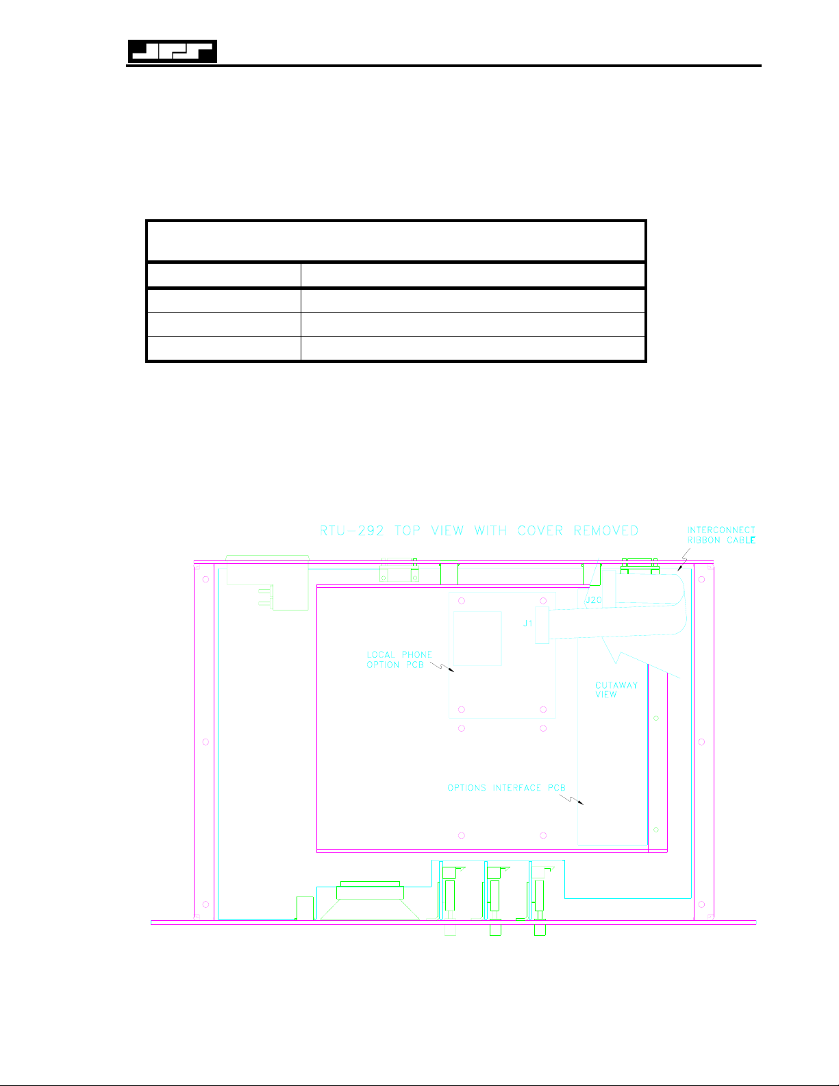
RTU-292 Operations Manual
7.3.2 LOCAL PHONE OPTION OPERATION
When the handset of the local phone is picked up, a special dial tone, generated by the RTU292, will be heard in its receiver. The user then has three options:
Table 7-5 Local Phone DTMF Commands
DTMF Command Function
0 Place a call to the RTU-292 Operator
1 Connect radio audio to the local phone
9 Place telephone calls to the outside PSTN line
Once the local phone user has selected a function and entered the associated DTMF character,
he may use any of the keypad commands that are available to a PSTN caller in the command
mode (see Table 3-1). It is important to note that the local phone audio into the RTU-292 does
not run through the unit's DSP circuitry and therefore cannot activate the VOX function.
Always de-activate the VOX function and use the manual key/unkey commands when
communicating over a radio via the local phone (see telephone commands in 3.7.3.4).
Figure 7-2 Local Phone Option Installation
JPS Communications, Inc.
7-5
Page 100

RTU-292 Operations Manual
7.4 VMM-100 OPTION
The VMM-100 VMR Module implements Voice Modulation Recognition (VMR) which
enables the receive audio path when speech is present and disables it when speech is not
present. This module also implements a form of noise reduction known as "dynamic peaking"
which reduces background white noise. These features are implemented with a DSP circuit on
the VMM board.
7.4.1 VMM-100 Hardware
The general purpose of the DSP hardware is to convert analog audio signals to the digital
domain, operate on and manipulate these signals digitally, then convert the result back to
analog.
7.4.1.1 VMM-100 DSP Section
The heart of the DSP section is the DSP chip itself, a TMS320C25. The unit runs at 40 MHz
and produces a 5 MHz signal at the U1-58 CLKOUT, which supplies timing to PEEL U3 and
ultimately to U2, the Analog Interface Chip. U2 then supplies an interrupt to the 320C25
approximately every 130 microseconds, which establishes the sample rate of about 8 kHz. The
DSP operating program is contained in EPROM chips U5 and U6. Two chips provide the
necessary 16-bit-wide architecture; the high byte is contained in U5 and the low byte in U6.
Static RAM chips U9 and U10 are used for temporary data storage during operation of the
program.
All of the "glue" logic necessary to interface the DSP with the various peripheral chips on the
board is provided by PEEL (Programmable Electrically Erasable Logic) U3.
U8 is a reset generator that insures an orderly power-up sequence for the DSP and associated
components. It senses the voltage on the +5V line and generates a reset while the voltage is
below approximately 4.55V. As the voltage rises above the threshold, a delay is generated by
C8 to insure processor clock stability before operation commences. Resistor R2 prevents U8
from resetting on short spikes on the 5V line.
Latch U4 provides an eight-bit parallel output from the DSP. Two of the outputs are used
(NR3 and NR4), while the other six are spare. Latch U12 provides an eight-bit parallel input to
the DSP. Two of the inputs are used (NR1 and NR2), while the other six are spare. Latch U11
provides a means for the DSP to read SW1 switch settings.
7.4.1.2 VMM-100 Analog Interface
Chip U2 provides the analog interface to the DSP section. This chip is type TLC32040 and
contains an A/D converter for the analog input, D/A converter for analog output, and an antialias filter before the A/D, and a reconstruction filter after the D/A. The chip derives its own
timing for these functions from the master clock provided by the DSP. These chips are
interfaced to the DSP via a serial bus.
Amplifier U13 is a dual op-amp that provides gain-of-one buffer amplifiers for the analog
audio input and output.
JPS Communications, Inc.
7-6
 Loading...