

Page 1

Title page
Nortel Communication Server 1000
Nortel Communication Server 1000 Release 4.5
Main Office Configuration for Survivable
Remote Gateway 50
Configuration Guide
Document Number: 553-3001-207
Document Release: Standard 2.00
Date: January 2006
Year Publish FCC TM
Copyright © Nortel Networks Limited 2006
All Rights Reserved
Produced in Canada
Information is subject to change without notice. Nortel Networks reserves the right to make changes in design
or components as progress in engineering and manufacturing may warrant.
Nortel, Nortel (Logo), the Globemark, This is the Way, This is Nortel (Design mark), SL-1, Meridian 1, and
Succession are trademarks of Nortel Networks.
Page 2

Page 3

4
Page 3 of 258
Revision history
January 2006
Standard 2.00. This document is up-issued for CR Q01202736, with
information on reconfiguring Call Server alarm notification levels if
necessary when configuring Adaptive Network Bandwidth Management. See
pages 76 and 84.
August 2005
Standard 1.00. This document is a new document to support
Communication Server 1000 Release 4.5.
Main Office Configuration for Survivable Remote Gateway 50 Configuration Guide
Page 4

Page 4 of 258 Revision history
553-3001-207 Standard 2.00 January 2006
Page 5

8
Page 5 of 258
Contents
List of procedures . . . . . . . . . . . . . . . . . . . . . . . . . . 9
About this document . . . . . . . . . . . . . . . . . . . . . . . 11
Subject .. . . . . . . . . . . . . . . . . . . . . . . . . . . . . . . . . . . . . . . . . . . . . . . . . 11
Applicable systems . . . . . . . . . . . . . . . . . . . . . . . . . . . . . . . . . . . . . . . . 12
Intended audience . . . . . . . . . . . . . . . . . . . . . . . . . . . . . . . . . . . . . . . . . 12
Conventions .. . . . . . . . . . . . . . . . . . . . . . . . . . . . . . . . . . . . . . . . . . . . . 12
Related information .. . . . . . . . . . . . . . . . . . . . . . . . . . . . . . . . . . . . . . . 13
Overview . . . . . . . . . . . . . . . . . . . . . . . . . . . . . . . . . 15
Contents .. . . . . . . . . . . . . . . . . . . . . . . . . . . . . . . . . . . . . . . . . . . . . . . . 15
Survivable Remote Gateway .. . . . . . . . . . . . . . . . . . . . . . . . . . . . . . . . 15
Main office hardware description . . . . . . . . . . . . . . . . . . . . . . . . . . . . . 17
Main office requirements . . . . . . . . . . . . . . . . . . . . . . . . . . . . . . . . . . . 20
Optional features to enhance SRG functionality .. . . . . . . . . . . . . . . . . 21
Normal Mode and Local Mode overview . . . . . . . . . . . . . . . . . . . . . . . 22
Bandwidth Management Overview .. . . . . . . . . . . . . . . . . . . . . . . . . . . 26
Capacity .. . . . . . . . . . . . . . . . . . . . . . . . . . . . . . . . . . . . . . . . . . . . . . . . 29
Branch office dialing plan . . . . . . . . . . . . . . . . . . . . . . . . . . . . . . . . . . . 30
Cross reference for branch office and SRG50 terminology . . . . . . . . . 32
Setting up the main office . . . . . . . . . . . . . . . . . . . 35
Contents .. . . . . . . . . . . . . . . . . . . . . . . . . . . . . . . . . . . . . . . . . . . . . . . . 35
Introduction . . . . . . . . . . . . . . . . . . . . . . . . . . . . . . . . . . . . . . . . . . . . . . 35
Main Office Configuration for Survivable Remote Gateway 50 Configuration Guide
Page 6

Page 6 of 258 Contents
SRG information required by the main office . . . . . . . . . . . . . . . . . . . 36
Main office information required by the SRG . . . . . . . . . . . . . . . . . . . 37
Zone parameters . . . . . . . . . . . . . . . . . . . . . . . . . . . . . . . . . . . . . . . . . . 39
Branch office IP Phone configuration at the main office . . . . . . . . . . . 46
Bandwidth Management . . . . . . . . . . . . . . . . . . . . 49
Contents . . . . . . . . . . . . . . . . . . . . . . . . . . . . . . . . . . . . . . . . . . . . . . . . 49
Introduction .. . . . . . . . . . . . . . . . . . . . . . . . . . . . . . . . . . . . . . . . . . . . . 50
Codec negotiation . . . . . . . . . . . . . . . . . . . . . . . . . . . . . . . . . . . . . . . . . 50
Configuring Bandwidth Management parameters . . . . . . . . . . . . . . . . 56
Adaptive Network Bandwidth Management . . . . . . . . . . . . . . . . . . . . 67
Tandem Bandwidth Management overview . . . . . . . . . . . . . . . . . . . . . 93
Dialing Plan Overview . . . . . . . . . . . . . . . . . . . . . . . . . . . . . . . . . . . . . 94
Network using Uniform Dialing Plan . . . . . . . . . . . . . . . . . . . . . . . . . . 96
Network using Coordinated Dialing Plan .. . . . . . . . . . . . . . . . . . . . . . 122
Alternative Call Routing for Network Bandwidth
Management . . . . . . . . . . . . . . . . . . . . . . . . . . . . . . 127
Contents . . . . . . . . . . . . . . . . . . . . . . . . . . . . . . . . . . . . . . . . . . . . . . . . 127
Description . . . . . . . . . . . . . . . . . . . . . . . . . . . . . . . . . . . . . . . . . . . . . . 127
Operating parameters . . . . . . . . . . . . . . . . . . . . . . . . . . . . . . . . . . . . . . 146
Feature interactions .. . . . . . . . . . . . . . . . . . . . . . . . . . . . . . . . . . . . . . . 148
Feature packaging . . . . . . . . . . . . . . . . . . . . . . . . . . . . . . . . . . . . . . . . . 149
Feature implementation using Command Line Interface . . . . . . . . . . . 149
Feature implementation using Element Manager . . . . . . . . . . . . . . . . . 151
Diagnostics . . . . . . . . . . . . . . . . . . . . . . . . . . . . . . . . . . . . . . . . . . . . . . 155
Maintenance . . . . . . . . . . . . . . . . . . . . . . . . . . . . . . . . . . . . . . . . . . . . . 162
Feature operation . . . . . . . . . . . . . . . . . . . . . . . . . . . . . . . . . . . . . . . . . 166
Dialing Plan configuration . . . . . . . . . . . . . . . . . . . 167
Contents . . . . . . . . . . . . . . . . . . . . . . . . . . . . . . . . . . . . . . . . . . . . . . . . 167
Overview .. . . . . . . . . . . . . . . . . . . . . . . . . . . . . . . . . . . . . . . . . . . . . . . 167
553-3001-207 Standard 2.00 January 2006
Page 7

Contents Page 7 of 258
On-net dialing plan . . . . . . . . . . . . . . . . . . . . . . . . . . . . . . . . . . . . . . . . 168
Off-net dialing plan . . . . . . . . . . . . . . . . . . . . . . . . . . . . . . . . . . . . . . . . 169
Routing calls . . . . . . . . . . . . . . . . . . . . . . . . . . . . . . . . . . . . . . . . . . . . . 170
H.323 zones .. . . . . . . . . . . . . . . . . . . . . . . . . . . . . . . . . . . . . . . . . . . . . 170
Zone-based digit manipulation . . . . . . . . . . . . . . . . . . . . . . . . . . . . . . . 171
Configuring PSTN access for SRG users in Normal Mode . . . . . . . . . 173
Dialing plan examples .. . . . . . . . . . . . . . . . . . . . . . . . . . . . . . . . . . . . . 193
Emergency Services configuration . . . . . . . . . . . . 225
Contents .. . . . . . . . . . . . . . . . . . . . . . . . . . . . . . . . . . . . . . . . . . . . . . . . 225
Overview . . . . . . . . . . . . . . . . . . . . . . . . . . . . . . . . . . . . . . . . . . . . . . . . 225
Emergency Services Access (ESA) .. . . . . . . . . . . . . . . . . . . . . . . . . . . 226
Configuring the NRS for ESA SPN . . . . . . . . . . . . . . . . . . . . . . . . . . . 238
Testing the ESDN number . . . . . . . . . . . . . . . . . . . . . . . . . . . . . . . . . . 238
Configuring ESA using Element Manager . . . . . . . . . . . . . . . . . . . . . . 239
Emergency Service using Special Numbers (SPN) .. . . . . . . . . . . . . . . 239
Enhanced UNIStim Firmware Download . . . . . . . . 241
Contents .. . . . . . . . . . . . . . . . . . . . . . . . . . . . . . . . . . . . . . . . . . . . . . . . 241
Description . . . . . . . . . . . . . . . . . . . . . . . . . . . . . . . . . . . . . . . . . . . . . . 241
Firmware upgrade . . . . . . . . . . . . . . . . . . . . . . . . . . . . . . . . . . . . . . . . . 242
Appendix A: Media Redirection Scenarios . . . . . . 245
List of terms . . . . . . . . . . . . . . . . . . . . . . . . . . . . . . . 251
Main Office Configuration for Survivable Remote Gateway 50 Configuration Guide
Page 8

Page 8 of 258 Contents
553-3001-207 Standard 2.00 January 2006
Page 9

10
Page 9 of 258
List of procedures
Procedure 1
Configuring ESN and SRG zones . . . . . . . . . . . . . . . . . 40
Procedure 2
Configuring branch office IP Phones at the
main office using LD 11 . . . . . . . . . . . . . . . . . . . . . . . . . 47
Procedure 3
Printing intrazone and interzone statistics for
a zone . . . . . . . . . . . . . . . . . . . . . . . . . . . . . . . . . . . . . . . . 63
Procedure 4
Displaying CAC parameters for one or more
zones . . . . . . . . . . . . . . . . . . . . . . . . . . . . . . . . . . . . . . . . 85
Procedure 5
Provisioning Tandem Bandwidth Management . . . . . .110
Procedure 6
Accessing the Zones web page . . . . . . . . . . . . . . . . . . . 152
Procedure 7
Printing zone ALTPrefix . . . . . . . . . . . . . . . . . . . . . . . . . 157
Procedure 8
Show Status . . . . . . . . . . . . . . . . . . . . . . . . . . . . . . . . . . .160
Procedure 9
Enabling a zone’s branch office behavior . . . . . . . . . .163
Main Office Configuration for Survivable Remote Gateway 50 Configuration Guide
Page 10

Page 10 of 258 List of procedures
Procedure 10
Suppress Alternative Call Routing for
NBWM alarms . . . . . . . . . . . . . . . . . . . . . . . . . . . . . . . . . 165
Procedure 11
Configuring the main office . . . . . . . . . . . . . . . . . . . . . . 175
Procedure 12
Configuring the NRS database . . . . . . . . . . . . . . . . . . . 184
Procedure 13
Configuring the branch office . . . . . . . . . . . . . . . . . . . . 187
Procedure 14
Testing PSTN access using an SRG IP Phone . . . . . . . 192
Procedure 15
Configuring the main office . . . . . . . . . . . . . . . . . . . . . . 231
Procedure 16
Configuring the branch office zone . . . . . . . . . . . . . . . . 237
Procedure 17
Testing ESDN using an SRG telephone . . . . . . . . . . . . 238
Procedure 18
Upgrading firmware . . . . . . . . . . . . . . . . . . . . . . . . . . . . 243
553-3001-207 Standard 2.00 January 2006
Page 11

14
Page 11 of 258
About this document
This document is a global document. Contact your system supplier or your
Nortel representative to verify that the hardware and software described are
supported in your area.
Subject
This document describes the Main Office Configuration for the Survivable
Remote Gateway 50: Configuration Guide (553-3001-207). Information in
this document complements information found in documents in the
Communication Server 1000 documentation suite, as listed in “Related
information” on page 13.
For information about how to configure the SRG50, see SRG50
Configuration Guide at http://www.nortel.com. Select Support &
Training > Technical Documentation Communication Servers >
Enterprise Communication Servers > Communication Server 1000S and
search for SRG.
Note on legacy products and releases
This NTP contains information about systems, components, and features that
are compatible with Nortel Communication Server 1000 Release 4.5
software. For more information about legacy products and releases, click the
Technical Documentation link under Support & Training on the Nortel
home page:
http://www.nortel.com
Main Office Configuration for Survivable Remote Gateway 50 Configuration Guide
Page 12

Page 12 of 258 About this document
Applicable systems
This document applies to the following systems:
• Communication Server 1000S (CS 1000S)
• Communication Server 1000M Chassis (CS 1000M Chassis)
• Communication Server 1000M Cabinet (CS 1000M Cabinet)
• Communication Server 1000M Half Group (CS 1000M HG)
• Communication Server 1000M Single Group (CS 1000M SG)
• Communication Server 1000M Multi Group (CS 1000M MG)
• Communication Server 1000E (CS 1000E)
Note: When upgrading software, memory upgrades may be required on
the Signaling Server, the Call Server, or both.
Intended audience
This document is intended for individuals responsible for configuring the
main office for Survivable Remote Gateway for organizations using CS 1000
systems.
Conventions
Terminology
In this document, the following systems are referred to generically as
“system”:
• Communication Server 1000S (CS 1000S)
• Communication Server 1000M (CS 1000M)
• Communication Server 1000E (CS 1000E)
•Meridian1
The following systems are referred to generically as “Small System”:
• Communication Server 1000M Chassis (CS 1000M Chassis)
553-3001-207 Standard 2.00 January 2006
Page 13

• Communication Server 1000M Cabinet (CS 1000M Cabinet)
The following systems are referred to generically as “Large System”:
• Communication Server 1000M Half Group (CS 1000M HG)
• Communication Server 1000M Single Group (CS 1000M SG)
• Communication Server 1000M Multi Group (CS 1000M MG)
Related information
This section lists information sources that relate to this document.
NTPs
The following NTPs are referenced in this document:
• Converging the Data Network with VoIP (553-3001-160)
• Electronic Switched Network: Signaling and Transmission Guidelines
(553-3001-180)
• Dialing Plans: Description (553-3001-183)
• Signaling Server: Installation and Configuration (553-3001-212)
About this document Page 13 of 258
• IP Peer Networking: Installation and Configuration (553-3001-213)
• Branch Office: Installation and Configuration (553-3001-214)
• Optivity Telephony Manager: Installation and Configuration
(553-3001-230)
• Software Input/Output: Administration (553-3001-311)
• Emergency Services Access: Description and Administration
(553-3001-313)
• Optivity Telephony Manager: System Administration (553-3001-330)
• Element Manager: System Administration (553-3001-332)
• IP Line: Description, Installation, and Operation (553-3001-365)
• ISDN Primary Rate Interface: Features (553-3001-369)
• Basic Network Features (553-3001-379)
Main Office Configuration for Survivable Remote Gateway 50 Configuration Guide
Page 14

Page 14 of 258 About this document
• SRG50 Configuration Guide
• Communication Server 1000M and Meridian 1: Small System Planning
and Engineering (553-3011-120)
• Communication Server 1000M and Meridian 1: Large System Planning
and Engineering (553-3021-120)
• Communication Server 1000S: Planning and Engineering
(553-3031-120)
• Communication Server 1000E: Planning and Engineering
(553-3041-120)
• Software Input/Output: Maintenance (553-3001-511)
Online
To access Nortel documentation online, click the Technical Documentation
link under Support & Training on the Nortel home page:
http://www.nortel.com
CD-ROM
To obtain Nortel documentation on CD-ROM, contact your Nortel customer
representative.
553-3001-207 Standard 2.00 January 2006
Page 15

34
Page 15 of 258
Overview
Contents
This section contains information about the following topics:
Survivable Remote Gateway. . . . . . . . . . . . . . . . . . . . . . . . . . . . . . . . . 15
Main office hardware description . . . . . . . . . . . . . . . . . . . . . . . . . . . . . 17
Main office requirements . . . . . . . . . . . . . . . . . . . . . . . . . . . . . . . . . . . 20
Optional features to enhance SRG functionality. . . . . . . . . . . . . . . . . . 21
Normal Mode and Local Mode overview . . . . . . . . . . . . . . . . . . . . . . . 22
Capacity. . . . . . . . . . . . . . . . . . . . . . . . . . . . . . . . . . . . . . . . . . . . . . . . . 29
Branch office dialing plan . . . . . . . . . . . . . . . . . . . . . . . . . . . . . . . . . . . 30
Cross reference for branch office and SRG50 terminology . . . . . . . . . 32
Survivable Remote Gateway
The Survivable Remote Gateway (SRG) extends CS 1000 features from a
main office to one or more remote SRG locations (branch offices). The
SRG50 Release 1.0 operates with the CS 1000 running Release 4.5 and is
backward compatible to Release 3.0 and Release 4.0. SRG does not operate
with CS 1000 Release 1.0 and Succession 1000 2.0 systems.
In addition to the SRG 1.0 model, which is positioned as the lower cost
alternative to the Media Gateway 1000B product, there is a new “mini” model
for the smaller branch office, known as the SRG50. The SRG50 is optimized
for the 5-32 user branch office.
Main Office Configuration for Survivable Remote Gateway 50 Configuration Guide
Page 16

Page 16 of 258 Overview
The SRG is implemented on a BCM50 platform and is connected to a
CS 1000 at the main office over a LAN or a WAN. This configuration allows
the call processing for the IP Phones at the SRG site to be centralized at the
main office. The Call Server at the main office provides the call processing
for the IP Phones in both the main office and branch offices. The SRG
provides call processing functionality to telephones in local mode and local
analog devices. The SRG also provides digital and analog trunk access to the
local Public Switched Telephone Network (PSTN).
In order for devices in the CS 1000 network to access analog devices at the
SRG or to access the PSTN at the SRG, virtual trunks are used over the LAN/
WAN.
If the main office fails to function, or if there is a network outage, the SRG
provides service to the telephones located at the branch office. This enables
the IP Phones to survive the outage between the branch office and the main
office.
The SRG is designed to work with a main office only if the main office and
the SRG use a common dialing plan. Any other configuration is not
guaranteed to work reliably. Since the Call Server and the SRG handle dialing
slightly differently, ensure that any settings you use for the main office, that
need to interact with the SRG, can be accommodated by the SRG call
processing.
Figure 1 on page 17 shows the networking among the main office, SRG, and
IP Phones.
553-3001-207 Standard 2.00 January 2006
Page 17
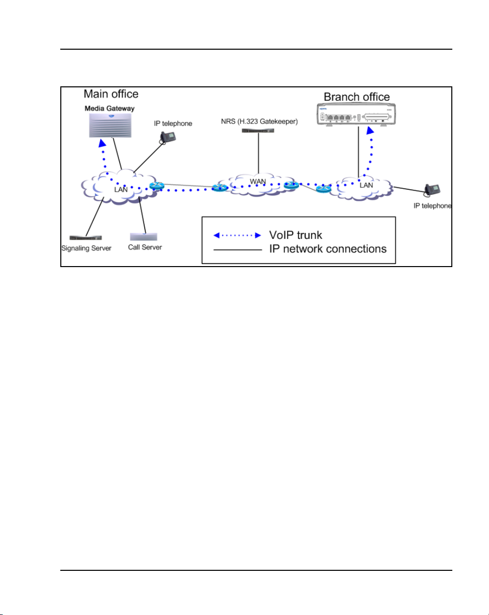
Figure 1:
SRG network
Main office hardware description
The main office must be one of the following systems:
Overview Page 17 of 258
• CS 1000S
• CS 1000E
• CS 1000M Cabinet
• CS 1000M Chassis
• CS 1000M HG
• CS 1000M SG
• CS 1000M MG
Note: Throughout this document, references to CS 1000 systems
encompass all CS 1000 system types.
The diagrams throughout this documentation show a CS 1000S main office.
All of the systems appearing in the list perform identical main office
functions as far as the SRG is concerned. For information about the SRG,
refer to SRG50 Configuration Guide.
Main Office Configuration for Survivable Remote Gateway 50 Configuration Guide
Page 18

Page 18 of 258 Overview
Signaling Server
The Signaling Server is required at the main office only. It provides the
following functions:
• Terminal Proxy Server (TPS)
— The TPS provides a connection from the IP Phones to the Call
• Web server for Element Manager and Network Routing Service (NRS)
Manager
A second Signaling Server can be used to provide redundancy in the case of
failure in the primary Signaling Server at the main office.
A similar function to the Signaling Server exists at the SRG.
The Signaling Server supports both en bloc and overlap signaling. En bloc
signaling is standard. If overlap signaling is to be used, Nortel recommends
that it be installed and enabled on all Signaling Servers in the network. Failure
to do so results in delays in call completion due to overlap to en bloc
conversion.
Server. It also provides a connection path from a virtual trunk to the
Call Server.
For more information about the Signaling Server, refer to Signaling Server:
Installation and Configuration (553-3001-212). For more information about
H.323 and overlap signaling, refer to IP Peer Networking: Installation and
Configuration (553-3001-213).
Network Routing Service
• The NRS application provides network-based routing, combining the
following into a single application:
• H.323 Gatekeeper — provides central dialing plan management and
routing for H.323-based endpoints and gateways.
Note: NRS also contains SIP Redirect Server but SIP Trunks are not
supported on an SRG.
553-3001-207 Standard 2.00 January 2006
Page 19

Overview Page 19 of 258
• NRS Database — stores the central dialing plan in XML format for the
H.323 Gatekeeper. The H.323 Gatekeeper accesses this common
endpoint and gateway database.
• Network Connect Server (NCS) — used only for Media Gateway
1000B (MG 1000B), SRG, Geographic Redundancy and Virtual Office
solutions. The NCS allows the Line TPS (LTPS) to query the NRS using
the UNIStim protocol.
• NRS Manager web interface — the NRS provides its own web
interface to configure the H.323 Gatekeeper and the NCS.
The NRS application provides routing services to H.323 devices. The H.323
Gatekeeper can be configured to support H.323 routing services. The H.323
Gatekeeper can reside on the same Signaling Server.
Each system in an IP Peer network must register to the NRS. The NRS
software identifies the IP addresses of systems based on the network-wide
numbering plan. NRS registration eliminates the need for manual
configuration of IP addresses and numbering plan information at every site.
When configuring the NRS it is necessary to enable the NCS. Ensure that the
check box “Network Connection Server enabled” is checked in the NRS
configuration window of CS 1000 Element Manager.
For information about configuring the NRS, refer to IP Peer Networking:
Installation and Configuration (553-3001-213).
Telephones
The SRG supports the following telephones:
• IP Phone 2001
• IP Phone 2002
• IP Phone 2004
• IP Phone 2007
• IP Softphone 2050
• Mobile Voice Client (MVC) 2050
Main Office Configuration for Survivable Remote Gateway 50 Configuration Guide
Page 20

Page 20 of 258 Overview
• Analog (500/2500-type) telephones
• WLAN Handset 2210/2211
Note: Throughout this document, the IP Phones in this list are referred
to collectively as IP Phones.
Main office requirements
The branch office requires the following at the main office:
• CS 1000 hardware, running Succession 3.0, CS 1000 Release 4.0, or
CS 1000 Release 4.5.
• IP Peer H.323 Trunk (H323_VTRK) package 399. This package is
required to support H.323 functionality. Package 184 is included with
package 399.
• The main office must have a software Service Level of 2 or higher to
work with the branch office.
• Ensure that you have ordered enough IP user and Virtual Trunk licenses
at the main office to support the SRG50 or the capacity of your branch
office.
The main office requires the following software packages to support the
specified Basic Network features. Refer to Basic Network Features (5533001-379) for more information about these features.
• Network Call Back Queuing (MCBQ) package 38. This package is
required for SRG IP Phones to invoke any queuing feature or ringback
when free.
• Network Speed Call (NSC) package 39. This package is required for
SRG IP Phones to invoke the Network Speed Call feature.
The main office requires the following software packages to support the
specified ISDN Primary Rate Interface features. Refer to ISDN Primary Rate
553-3001-207 Standard 2.00 January 2006
Page 21

Overview Page 21 of 258
Interface: Features (553-3001-369) for more information about these
features.
• Network Attendant Service (NAS) package 159. This package is
required for analog (500/2500-type) telephones in the branch office to
access attendant services when the attendant is configured on the main
office.
• Network Message Services (NMS) package 175. This package is
required for analog (500/2500-type) telephones in the branch office to
share the voicemail system in the main office. For any configurations
using centralized CallPilot on the main office with one or more branch
offices in separate time zones, the NMS package is required at the main
office for the branch IP Phones.
Optional features to enhance SRG functionality
• Network Alternate Route Selection (NARS) package 58. Refer to Basic
Network Features (553-3001-379).
• Overlap Signaling (OVLP) package 184. This package is optional; it is
required for overlap signaling. It is packaged with H.323 Virtual Trunk
(H323_VTRK) package 399 (Release 4.0 only).
• Emergency Services Access (ESA) package 329. This package is
optional; it is required only to receive 911/ESA features in North
American and some Caribbean and Latin American (CALA) markets.
Refer to Emergency Services Access: Description and Administration
(553-3001-313).
• Virtual Office (VIRTUAL_OFFICE) package 382. This package is
optional; it is required only for Virtual Office functionality.
• Network Signaling (NSIG) package 37. This package is optional for
SRG IP Phones to access set-based Network Class of Service (NCOS)
features.
• Adaptive Network Bandwidth Management package 407.
• Alternative Call Routing for Network Bandwidth Management.
For software and hardware requirements for SRG, refer to SRG50
Configuration Guide.
Main Office Configuration for Survivable Remote Gateway 50 Configuration Guide
Page 22

Page 22 of 258 Overview
Normal Mode and Local Mode overview
Normal Mode
IP Phones that are physically located at the SRG but are registered with the
main office are in Normal Mode. The main office provides centralized call
processing for the SRG IP Phones. These telephones are registered to the
main office TPS and are controlled by the Call Server at the main office.
Users of the SRG IP Phones receive the features, key layout, and tones of the
main office Call Server. This provides feature and application transparency
between the branch office and the main office.
Local Mode
An IP Phone at the SRG may be in Local Mode for two different reasons;
1 IP Phone may have just booted up.
2 IP Phone cannot communicate to the main office because of a WAN
failure or a failure of the main office components.
Devices that are physically located with the SRG and are controlled by the
SRG system are said to be in Local Mode. These devices consist of analog
telephones, analog devices, such as, fax, and may include IP Phones.
Normally IP Phones are registered to the main office, in Normal Mode;
however, when the IP Phone cannot reach the main office, it reverts to Local
Mode.
IP Phone users in Normal Mode use the feature set on the main office. IP
Phone users in Local Mode receive only those features and tones that are
provisioned on the SRG. Users of analog (500/2500-type) telephones always
use the feature set on the SRG.
For information about the features supported in Local Mode, refer to SRG50
Configuration Guide.
Survivability
SRG provides survivability against WAN failure, main office Call Server
failure, main office Signaling Server failure, and Gatekeeper failure.
553-3001-207 Standard 2.00 January 2006
Page 23

Overview Page 23 of 258
SRG supports the Geographic Redundancy feature. For further information
about Geographic Redundancy, see Communication Server 1000: System
Redundancy (553-3001-307).
In the event of a WAN failure, the SRG IP Phones lose communication with
the main office. This causes the SRG IP Phones to reset and register with the
SRG. The IP Phones then operate in Local Mode, providing services based on
a limited SRG feature set, which has significant differences from the CS 1000
software. For further information about services and features supported on
the SRG, refer to SRG50 Configuration Guide.
If the main office Call Server fails and call processing services are provided
by an Alternate Call Server, the SRG IP Phones reset and reregister with the
Alternate Call Server and receive call processing services from it. If no
Alternate Call Server is available, the SRG IP Phones go to Local Mode while
the SRG attempts to find an Alternate Call Server by way of the NCS.
If the main office Signaling Server fails and an Alternate Signaling Server is
available, the SRG IP Phones reset and reregister with the SRG. The SRG will
then query the NCS for the Alternate Signaling Server’s IP address. The SRG
will redirect the IP Phone to the Alternate Signaling Server and continue to
receive call processing services from the main office Call Server. If no
Alternate Signaling Server is available, the SRG IP Phones reset and register
with the SRG in Local Mode.
When an IP Phone at the SRG first boots up, it attempts to communicate with
the SRG. After it establishes communications with the SRG, the SRG
redirects it to the main office. When the SRG IP Phone attempts to register
with the main office, the SRG first queries the Primary NRS (NCS) for the
main office Virtual Trunk node IP address to redirect the IP Phone. If the
Primary NRS (NCS) is down or unreachable, the SRG queries the
Alternate NRS (H.323 Gatekeeper), if one is specified. If it receives a
positive response, the SRG IP Phone is redirected to the specified main office.
Otherwise, if neither a Primary or an Alternate NRS (H.323 Gatekeeper) is
available, the SRG IP Phone remains in Local Mode, and receives call
processing services from the SRG until communication can be reestablished.
SRG IP Phones in Normal Mode remain registered with the main office if the
Primary NRS fails and no Alternate NRS is available. They can call any main
office telephone or IP Phones in Normal Mode in other branch offices.
Main Office Configuration for Survivable Remote Gateway 50 Configuration Guide
Page 24

Page 24 of 258 Overview
However, they cannot call any SRG analog (500/2500-type) telephones or
any external numbers through the SRG trunks because the Virtual Trunks are
not available. (SRG analog [500/2500-type] telephones are accessible if
alternate routing is available through the PSTN.)
Recovery to Normal Mode
If an IP Phone is in Local Mode due to WAN failure or main office
component failure, the SRG tries to communicate with the main office TPS
at regular intervals. Once communication is established with the main office
call server, the idle SRG IP Phones are automatically redirected and
reregistered to the main office. IP Phones that were busy at the time
communication was reestablished complete the call in Local Mode, and then
reregister with the main office after the call is complete.
Local Mode operation
When an SRG IP Phone is in Local Mode, the user has full access to the
services configured at the SRG (analog devices or analog or digital trunks)
and to other IP Phones registered to the SRG. In Local Mode, the IP Phones
can make local calls to other IP Phones and other analog (500/2500-type)
telephones at the branch office. They can also be used to make outgoing
PSTN calls and receive incoming calls as usual. SRG IP Phones can access
the main office IP Phones or other branches by routing through the local
PSTN.
When a telephone or trunk in the main office calls an SRG IP Phone that
has switched to Local Mode due to WAN failure, the call is treated
according to the main office call redirection configuration (such as
forwarding to voicemail or continuous ringback).
Testing the telephone in Local Mode
From Normal Mode, the branch user has the option of going to Local Mode
manually by resetting the telephone or using Test Local Mode. The test can
be performed by the user at any time and does not require a password. This
test is invoked from the IP Phone.
553-3001-207 Standard 2.00 January 2006
IMPORTANT!
Page 25

Nortel recommends testing Local Mode operation after changing the
provisioning for a telephone on the SRG.
To ensure that users do not forget to resume Normal Mode operation, the
SRG redirects the telephone to the main office to return the telephone to
Normal mode. This occurs if the telephone remains registered to the SRG in
Test Local Mode for ten minutes (default setting). Alternatively, the user can
press the Quit key
For further information about Local Mode functionality for SRG, refer to
SRG50 Configuration Guide.
Virtual Trunks
In order for endpoints in the CS1000 network to access endpoints in local
mode at the SRG or to access the PSTN at the SRG, Virtual Trunks are used
over the LAN/WAN.
Virtual Trunks are software components that provide the trunking features of
the Meridian Customer-Defined Network (MCDN) feature set. Access to
PSTN digital or analog trunks at the branch office occurs through the MCDN
Virtual Trunk.
Overview Page 25 of 258
from the set to return to Normal Mode.
X
For more information about Virtual Trunks, refer to IP Peer Networking:
Installation and Configuration (553-3001-213).
Note: Virtual Trunks are sometimes referred to as H.323 IP Peer Trunks.
In the SRG50 Configuration Guide, Virtual Trunks are referred to as IP
Trunks.
IP Phone calls
When an IP Phone calls another IP Phone, each telephone receives the
address of the other to exchange media directly between the telephones.
When in Normal Mode, an SRG IP Phone calling a main office IP Phone does
not require any trunking to set up the call. However, LAN/WAN bandwidth
is used to provide a media path for the call. For more information on Direct
IP media path functionality, see IP Peer Networking: Installation and
Configuration (553-3001-213).
Main Office Configuration for Survivable Remote Gateway 50 Configuration Guide
Page 26

Page 26 of 258 Overview
Bandwidth Management Overview
For a complete overview of Bandwidth Management, refer to the Converging
the Data Network with VoIP (553-3001-160), and for details on
configuration, refer to “Bandwidth Management” on page 49.
Network Bandwidth Management
Network Bandwidth Management allows for a limit to be placed on the
amount of interzone bandwidth allowed between IP Phones in Normal Mode
at the SRG and the rest of the CS 1000 network.
As well, it allows for the selection of interzone bandwidth codecs for calls
between the IP Phones in Normal Mode and the rest of the CS 1000 network.
Adaptive Network Bandwidth Management
Adaptive Network Bandwidth Management allows the system to dynamically
react to Quality of Service (QoS) degradation and take corrective action.
Network Bandwidth Management Zones
A zone is a collection of IP Phones that:
• share similar IP bandwidth restrictions
• are geographically close to one another
• are all in the same time zone
• are all in the same PSTN dialing plan
The Network Bandwidth Management Zone is made up of the VPNI and the
zone. The VPNI of the main office and all the SRG associated with it must be
the same.
Each SRG must have its own unique zone number and configured in the main
office Call Server and the SRG.
Note: Throughout this document, the term “zone” is defined as a
Bandwidth Management Zone, not an NRS (H.323 Gatekeeper) Zone.
Refer to “Bandwidth Management” on page 49.
553-3001-207 Standard 2.00 January 2006
Page 27

Miscellaneous items
Time of Day
Because the SRG IP Phones, in Normal Mode, receive their clock information
from the main office, which may be located in a different time zone, the main
office must be able to provide a different time of day for these phones.
The time zone of the SRG is configured with the SRG zone at the main office.
The time zone adjusts the main office time for display at the SRG. SRG
telephones then display the correct time of the SRG, rather than that of the
main office. For any configurations using centralized Call Pilot on the main
office with one or more branch offices in separate time zones, the NMS
package is required at the main office for the branch IP Phones.
SRG IP Phone to local PSTN calls
When an SRG IP Phone in Normal Mode dials a local PSTN number, the call
is processed by the main office Call Server. The dialed digits are modified
according to the dialing plan information configured in the zone for the SRG
IP Phone.
The call is configured to be routed over the Virtual Trunk to the branch office.
The SRG then tandems the call to the local PSTN.
Overview Page 27 of 258
Likewise, long distance calls can also be configured.
IMPORTANT!
If you use one Access Code for both local and long distance calls, and
that Access Code is associated with a branch office zone, all calls (local
and long distance) are routed through the SRG.
IP Phone to analog (500/2500-type) telephone calls
When an IP Phone in Normal Mode at the SRG calls an analog (500/2500type) telephone of the same SRG, the call is processed at the main office Call
Server. A Virtual Trunk route is selected according to the digits dialed. The
call is routed over a Virtual Trunk to the branch office. The SRG processes
the incoming Virtual Trunk call and terminates it to the local analog (500/
Main Office Configuration for Survivable Remote Gateway 50 Configuration Guide
Page 28

Page 28 of 258 Overview
2500-type) telephone. Since this is a call between IP and circuit-switched
devices, a DSP resource on a Media Card is allocated and connected to the
analog (500/2500-type) telephone. The IP address of the DSP resource is
returned to the main office Call Server so a direct media path between the
IP Phone and the DSP resource can be set up when the call is established.
Refer to IP Peer Networking: Installation and Configuration (553-3001-213)
for details.
Conference calls
When an SRG user initiates a conference call, the conference facilities of the
main office are used. This means that in a conference among three SRG users,
the LAN/WAN bandwidth of three media paths is used. The calls are
controlled by the main office, except in Local Mode. In Local Mode, SRG
users do not have access to conferencing.
553-3001-207 Standard 2.00 January 2006
Page 29

Capacity
Overview Page 29 of 258
Networking consideration
A fault condition can occur if IP Phones use a different route to the main
office than that used by the SRG.
CAUTION — Service Interruption
If the network is planned so that IP Phones use a different
route to the main office than that used by the SRG, a fault
condition can occur. When the SRG can ping the main
office but the IP Phone cannot ping the main office due to
a network outage, an IP Phone registration can force the
telephone into a cycle of registering locally, being
redirected to the main office, rebooting, and then
registering locally again. When this cycle occurs, further
diagnose the network outage.
Each CS 1000 main office can support up to 255 branch offices, which can be
made up of any combination of SRGs and MG 1000Bs. SRG50 supports up
to 32 IP Phone users. However, since all IP Phones register with the main
office, the governing factor is the maximum number of IP Phones that can be
supported at the main office. This means the total number of IP Phones in all
offices can be no greater than the capacity of the main office. Refer to one of
the following documents to determine the total number of phones your system
can support:
• Communication Server 1000S: Planning and Engineering (553-3031-
120)
• Communication Server 1000E: Planning and Engineering (553-3041-
120)
• Communication Server 1000M and Meridian 1: Large System Planning
and Engineering (553-3021-120)
• Communication Server 1000M and Meridian 1: Small System Planning
and Engineering (553-3011-120).
Main Office Configuration for Survivable Remote Gateway 50 Configuration Guide
Page 30

Page 30 of 258 Overview
Virtual Trunks capacity
The SRG capacity to support a number of simultaneous calls depends on the
specific codec type used.
In Normal Mode, the codec selection used is controlled by specific
programming of the CS 1000. In this case: SRG 505 supports up to a
maximum of 15 Virtual trunks unless both the intrazone and interzone codecs
are configured as Best Quality (G.711), in which case the maximum number
of Virtual Trunks would be 24.
In Local Mode, if the WAN has failed, there are no longer any Virtual Trunks
available between the SRG and CS 1000. However, the SRG will continue to
convert calls from IP terminals for communication through the PSTN. Nortel
recommends you use G.711 codec. In this case, if G.711 is used, the number
of simultaneous calls from IP terminals to the PSTN supportable is a
maximum of 24.
Branch office dialing plan
Since IP Phone users can be located at a branch office equipped with an SRG,
the routing of calls to the local gateway is important (especially when toll
charges apply to calls made from the central Call Server that controls the
telephone). The administrator can configure digit manipulation through zone
attributes for IP Phones to select a main office or branch office that provides
PSTN access local to the destination of the call.
Calls from the PSTN to users within the network can be routed with the
various ESN numbering plan configurations.
To access local PSTN resources, outgoing calls can be routed using ESN as
well as zone parameters that enable digit insertion. The zone parameters force
calls made by an SRG user to be routed to the desired local PSTN facilities.
Note: Outgoing calls can include local and, optionally, long distance
calls.
Nortel recommends that the Branch User ID (BUID) be the same at the
branch office as the DN at the main office. A BUID has a maximum of 15
digits. Under the recommended Coordinated Dialing Plan (CDP), the BUID
553-3001-207 Standard 2.00 January 2006
Page 31

can be an extension (for example, 4567). Under the Uniform Dialing Plan
(UDP), it is the user’s main office DN, the Location Code (LOC), plus the
Access Code (for example, 6 343-5555).
Note: The main office DN must be an ESN compliant DN. See “ESN
Access Codes” on page 31.
For more information about dialing plans and configuration, see “Dialing
Plan configuration” on page 167. For more information about the branch
office dialing plan, refer to SRG50 Configuration Guide.
ESN Access Codes
ESN data is configured with two Access Codes, called AC1 and AC2. AC1
normally applies to long distance calls, whether placed on or off the
customer’s private network (for example, dialing “6”). AC2 normally applies
to local calls (for example, “9”). For more information, refer to Electronic
Switched Network: Signaling and Transmission Guidelines (553-3001-180).
Music on Hold
For SRG users in Normal Mode, the main office provides music to the user if
Music on Hold is provisioned. The use of the G.729A/AB codec between the
main office and the branch office may impact the music quality.
Overview Page 31 of 258
Note: G.723 codec is not supported on SRG50.
Main Office Configuration for Survivable Remote Gateway 50 Configuration Guide
Page 32

Page 32 of 258 Overview
Cross reference for branch office and SRG50 terminology
Table 1 lists configuration-related terms and contexts where branch office
and SRG50 terminology differ.
Table 1: Cross reference for branch office and SRG50 terminology (Part 1 of 2)
Term or context Branch office SRG50
dialing plan on-net/off-net dialing Private/Public network
dialing
routing distant steering codes (DSC),
Trunk steering codes (TSC),
Local steering codes (LSC)
Digit manipulation table dial-out digits (routing)
alternate routing selection Facility Restriction Level (FRL) scheduled call routing
Type of number CDP/UDP/TNDN CDP/UDP/no equivalent
Numbering Plan ID ISDN/Telephony
(E.164),Private, Telephony
(E.163), Telex, (F.69), Data
(X.121), National Standard
BUID Private DN length
bandwidth management zone Zone ID
Trunks public exchange PSTN
virtual trunk IP trunk
access codes (SRG50:
destination codes)
7 = system trunk access
8 = Basic Alternate Route
Selection (BARS)/Network
Alternate Route Selection
(NARS)
call routing, destination
codes, line pool access
codes
Private
7 = not assigned
8 = not assigned
9 = line pool A access code
9 = public exchange access
553-3001-207 Standard 2.00 January 2006
Page 33

Overview Page 33 of 258
Table 1: Cross reference for branch office and SRG50 terminology (Part 2 of 2)
Term or context Branch office SRG50
Network Class of Service
(NCOS)
telephone numbers
(internal, not PSTN)
TN DN, MOTN
Main Office Configuration for Survivable Remote Gateway 50 Configuration Guide
Page 34

Page 34 of 258 Overview
553-3001-207 Standard 2.00 January 2006
Page 35

48
Page 35 of 258
Setting up the main office
Contents
This section contains information on the following topics:
Introduction . . . . . . . . . . . . . . . . . . . . . . . . . . . . . . . . . . . . . . . . . . . . . . 35
SRG information required by the main office. . . . . . . . . . . . . . . . . . . . 36
Main office information required by the SRG . . . . . . . . . . . . . . . . . . . 37
Zone parameters . . . . . . . . . . . . . . . . . . . . . . . . . . . . . . . . . . . . . . . . . . 39
Branch office IP Phone configuration at the main office . . . . . . . . . . . 46
Introduction
Main Office Configuration for Survivable Remote Gateway 50 Configuration Guide
This section describes the following information required to configure the
main office:
• SRG information required by the main office
• Main office information required by the SRG
• Zone parameters
• IP Phone passwords and parameters
• Branch office IP Phone configuration
Page 36

Page 36 of 258 Setting up the main office
For more information on main office configuration, refer to IP Peer
Networking: Installation and Configuration (553-3001-213).
SRG information required by the main office
The main office administrator must gather information about the SRG
system. The following information is required:
• an inventory of IP Phones that will be installed on the SRG so the
administrator knows what type of telephone to assign to each main office
terminal record
• information which allows the administrator to create an NRS
(H.323 Gatekeeper) entry for the SRG
• if using advanced routing, such as tandem dialing between systems, local
PSTN number for the SRG and the internal SRG routing codes that will
allow the main office to connect to the SRG and to tandem over the SRG
PSTN lines, is required.
Use Table 2 to record the information before setting up the SRG on the main
office server.
Table 2:
SRG information required for the main office configuration (Part 1 of 2)
SRG parameters
SRG public IP address
H.323 ID (gatekeeper identification of the SRG)
List of types and number of IP Phones
Note: Telephone types are hard-coded to the
Terminal Numbers (TNs) and the main office.
Therefore, install the same type of IP Phones to the
coordinating record on the SRG.
PSTN number to dial into the SRG (in local mode)
553-3001-207 Standard 2.00 January 2006
Page 37

Setting up the main office Page 37 of 258
Table 2:
SRG information required for the main office configuration (Part 2 of 2)
SRG parameters
Destination codes (steering codes) to route the main
office calls to the SRG and out through the SRG
PSTN lines
IP Ports that affect SRG traffic with the main office and
have been assigned firewall filters
For further information on port configuration, refer to
Converging the Data Network with VoIP (553-3001-
160) or SRG50 Configuration Guide.
Main office information required by the SRG
The main office administrator must supply numerous main office settings to
the SRG installer so that the SRG can be efficiently configured. In addition,
the main office administrator needs to supply the following information:
• a list of the terminal record numbers (TNs)
• a list of BUIDs (Prime DNs)
• if using advanced routing, such as tandem dialing between systems, main
office routing (steering) codes, are required
Use Table 3 to record main office information required by the SRG.
Table 3
Main office interoperation information (Part 1 of 3)
Main office components Information about this system
Main office IP network information:
Main office call server type S1000 (default)
Primary network connect server address
Alternate network connect server
Network Connect server port
Main Office Configuration for Survivable Remote Gateway 50 Configuration Guide
Page 38

Page 38 of 258 Setting up the main office
Table 3
Main office interoperation information (Part 2 of 3)
Main office components Information about this system
Trunk/telephony preferred codecs and jitter
buffers listed in order of preference
NRS (H.323 Gatekeeper) requirements
Indicate if the SRG needs to manually assign
ports with firewall filters.
Telephony programming:
DN length, DN (TN) range
Numbering plan ID Private (default)
Type of number
Note 1: SRG50 only supports CDP and UDP
dialing plans. Nortel recommends that the
SRG use CDP.
Note 2: The SRG supports only one dialing
plan option at a time. CDP and UDP dialing
plan options cannot be configured at the same
time in the same system.
Node ID
Virtual Private Network ID (VPNI)
Zone ID and dialing string information
requirements
Main office dial-up number (for PSTN calls to
the main office in Local Mode.
Access code to reach the main office PSTN
through VoIP trunks
553-3001-207 Standard 2.00 January 2006
Page 39

Setting up the main office Page 39 of 258
Table 3
Main office interoperation information (Part 3 of 3)
Main office components Information about this system
Zone dialing:
• ZDP appended to SRG IP Phone PSTN
dialing strings to redirect the call to SRG
PSTN
• Any steering codes (destination codes)
that must be mirrored by SRG
programming
IP Phone configuration:
MOTN/BUID list, including which type of
IP Phone is assigned to each number
Note: Make note of the leading number, as
SRG uses this as the DN range for CDP
dialing. If the DCP access code is more than
one digit, the second digit number must also
be used to further define the DN range.
Current IP Phone firmware version
Is a VLAN configured on the network?
Zone parameters
Zone parameters must be configured at both the main office Call Server and
the SRG. The main office procedure is similar to an IP Peer Network
configuration with the branch office-specific configuration outlined in this
chapter.
Zone parameters are defined at the main office in LD 117 (see Procedure 1 on
page 40) and applied to IP Phones in LD 11.
Use Procedure 1 on page 40 to configure ESN and SRG zones.
Main Office Configuration for Survivable Remote Gateway 50 Configuration Guide
Page 40

Page 40 of 258 Setting up the main office
Procedure 1
Configuring ESN and SRG zones
IMPORTANT!
Before and after an upgrade, perform a data dump (using LD 43 EDD or
through Element Manager) on the Call Server or SSC to back up
existing data.
1 Configure the Home Location Code (HLOC) and the Virtual Private
Network Identifier (VPNI).
LD 15 – Configure Customer Data Home Location Code and Virtual Private Network
Identifier (Part 1 of 2)
Prompt Response Description
REQ: CHG Change existing data.
TYPE: NET ISDN and ESN Networking options
CUST
0-99
0-31
...
CLID YES Allow Calling Line Identification option
- ENTRY xx CLID entry to be configured
- - HLOC 100-9999999 Home Location code (ESN) (3-7 digits)
553-3001-207 Standard 2.00 January 2006
Customer number
Range for Large System and CS 1000E system
Range for Small System, CS 1000S system, Media
Gateway 1000B, and Media Gateway 1000T
Page 41

Setting up the main office Page 41 of 258
LD 15 – Configure Customer Data Home Location Code and Virtual Private Network
Identifier (Part 2 of 2)
Prompt Response Description
ISDN YES Integrated Services Digital Network
-VPNI (0)-16383 Virtual Private Network Identifier for Bandwidth
Management feature
X = Disables feature
1-16383 = Enables feature
<cr> = No Change
2 Configure the zone properties for IP Telephony bandwidth management.
Use LD 117 or Element Manager. Refer to IP Peer Networking:
Installation and Configuration (553-3001-213).
Main Office Configuration for Survivable Remote Gateway 50 Configuration Guide
Page 42

Page 42 of 258 Setting up the main office
Note: The branch office zone number and zone bandwidth management
parameters at the main office must match the corresponding branch office
zone number and zone bandwidth management parameters at the branch
office.
IMPORTANT!
Zone 0, the default zone, must not be configured as a branch office
zone. Network Bandwidth Management does not support zone 0. If
zone 0 is configured as an branch office zone, the Bandwidth
Management feature is not activated.
3 Define the zone parameters for the branch office. Use LD 117 or Element
Manager. Refer to IP Peer Networking: Installation and Configuration
(553-3001-213).
LD 117 – Define zone parameters for the branch office.
Command Description
CHG ZBRN <Zone> <yes|no>
Define a zone as a branch office zone.
CHG ZDST <Zone> <yes|no> <StartMonth> <StartWeek> <StartDay> <StartHour>
<EndMonth> <EndWeek> <EndDay> <EndHour>
If the branch office observes Daylight Savings Time (DST), these
parameters specify the start and end of DST. During DST, the clock
automatically advances one hour forward.
CHG ZTDF <Zone> <TimeDifferencefromMainOffice>
Specified in minutes, the time difference between main office and branch
office when both are not in DST.
CHG ZDES <Zone> <ZoneDescription
A name to render data display more meaningful.
553-3001-207 Standard 2.00 January 2006
Page 43

Setting up the main office Page 43 of 258
4 Enable the features for the branch office zone in LD 11.
LD 117 – Enable features for an SRG zone.
Command Description
ENL ZBR <zone> ALL Enables features for branch office <zone>.
End of Procedure
Configuring zone parameters using CS 1000 Element Manager
Use Element Manager to configure the branch office specific zone properties
and time difference.
1 Select IP Telephony > Zones in Element Manager navigator.
The Zones window opens (Figure 2 on page 44). The zone list is the main
window used for zone configuration.
Main Office Configuration for Survivable Remote Gateway 50 Configuration Guide
Page 44

Page 44 of 258 Setting up the main office
Figure 2
Zone List web page
2 Select the zone to be configured and configure the following properties.
• Basic Property and Bandwidth Management (see Figure 3 on
page 45)
• Dialing Plan and Access Codes (see Figure 61 on page 192)
• Emergency Service Information (see Figure 78 on page 239)
• Time Difference and Daylight Saving Time Property (see Figure 4 on
page 46)
553-3001-207 Standard 2.00 January 2006
Page 45

Setting up the main office Page 45 of 258
Figure 3
Zone Basic Property and Bandwidth Management web page
Main Office Configuration for Survivable Remote Gateway 50 Configuration Guide
Page 46

Page 46 of 258 Setting up the main office
Figure 4
Zone Time Difference and Time web page
Zone parameters must be configured on the main office and the branch office.
For information on configuring zones, refer to “Bandwidth Management” on
page 49.
Branch office IP Phone configuration at the main office
After the branch office zones and passwords are provisioned, provision the
branch office IP Phones at the main office. These can be provisioned using
OTM (see “Branch office IP Phone configuration using OTM” on page 47)
or LD 11 (see Procedure 2).
553-3001-207 Standard 2.00 January 2006
Page 47

Setting up the main office Page 47 of 258
Note: There is no automatic data synchronization between the main
office Call Server and SRG. The technician must provision the telephone
on both the Call Server and the SRG.
Branch office IP Phone configuration using OTM
At the main office, OTM can be used to configure branch office IP Phones.
Use Telephone Pages to configure the telephones to include the following:
• Terminal Type
•TN
• Customer Number
• Branch Office Zone
• Prime DN corresponding to the BUID
Refer to Optivity Telephony Manager: System Administration (553-3001-
330) for details.
Branch office IP Phone configuration using LD 11
Use Procedure 2 at the main office to configure branch office IP Phones.
Procedure 2
Configuring branch office IP Phones at the main office using LD 11
1 Configure the branch office zones and dialing plan. See Procedure 1 on
page 40.
2 Configure the following telephone data in LD 11:
• Terminal type
• Customer Number
•TN
Main Office Configuration for Survivable Remote Gateway 50 Configuration Guide
Page 48

Page 48 of 258 Setting up the main office
•Zone
• Prime DN to correspond to BUID
LD 11 – Provision Branch User and SCPW at the main office
Prompt Response Description
REQ: NEW CHG Add new data, or change existing data.
TYPE: a...a Terminal type.
Type ? for a list of possible responses.
CUST xx Customer number as defined in LD 15.
ZONE 0-255 Zone number to which the IP Phone belongs. The
zone prompt applies only when the TYPE is i2001,
i2002, i2004, or i2050. Zone number is not checked
against LD 117.
...
SCPW xxxx Station Control Password
Must equal Station Control Password Length (SCPL)
as defined in LD 15. Not prompted if SCPL = 0.
Precede with X to delete.
553-3001-207 Standard 2.00 January 2006
End of Procedure
Page 49

126
Page 49 of 258
Bandwidth Management
Contents
This section contains information on the following topics:
Introduction . . . . . . . . . . . . . . . . . . . . . . . . . . . . . . . . . . . . . . . . . . . . . . 50
Codec negotiation . . . . . . . . . . . . . . . . . . . . . . . . . . . . . . . . . . . . . . . . . 50
Codec selection. . . . . . . . . . . . . . . . . . . . . . . . . . . . . . . . . . . . . . . . . 53
Codec selection algorithms. . . . . . . . . . . . . . . . . . . . . . . . . . . . . . . . 53
Interoperability between CS 1000 and SRG . . . . . . . . . . . . . . . . . . . . . 56
Zones . . . . . . . . . . . . . . . . . . . . . . . . . . . . . . . . . . . . . . . . . . . . . . . . 57
Configuration rules. . . . . . . . . . . . . . . . . . . . . . . . . . . . . . . . . . . . . . 57
Network Planning. . . . . . . . . . . . . . . . . . . . . . . . . . . . . . . . . . . . . . . 57
Enabling codecs . . . . . . . . . . . . . . . . . . . . . . . . . . . . . . . . . . . . . . . . 58
Configuring Bandwidth Management . . . . . . . . . . . . . . . . . . . . . . . 59
Maintenance commands . . . . . . . . . . . . . . . . . . . . . . . . . . . . . . . . . . 63
Adaptive Network Bandwidth Management. . . . . . . . . . . . . . . . . . . . . 67
Description . . . . . . . . . . . . . . . . . . . . . . . . . . . . . . . . . . . . . . . . . . . . 67
Feature packaging. . . . . . . . . . . . . . . . . . . . . . . . . . . . . . . . . . . . . . . 75
Configuration rules. . . . . . . . . . . . . . . . . . . . . . . . . . . . . . . . . . . . . . 75
Configuring Adaptive Network Bandwidth Management . . . . . . . . 76
Maintenance commands . . . . . . . . . . . . . . . . . . . . . . . . . . . . . . . . . . 85
Tandem Bandwidth Management overview . . . . . . . . . . . . . . . . . . . . . 93
Dialing Plan Overview . . . . . . . . . . . . . . . . . . . . . . . . . . . . . . . . . . . . . 94
Network using Uniform Dialing Plan . . . . . . . . . . . . . . . . . . . . . . . . . . 96
Network using Coordinated Dialing Plan . . . . . . . . . . . . . . . . . . . . . . . 122
Main Office Configuration for Survivable Remote Gateway 50 Configuration Guide
Page 50

Page 50 of 258 Bandwidth Management
Introduction
CS 1000 supports Bandwidth Management on a network-wide basis so that
voice quality can be managed between multiple Call Servers.
Bandwidth management allows for codec selection and bandwidth limitations
to be placed on calls, depending on whether the calls are intrazone or
interzone.
Adaptive Network Bandwidth Management is an enhancement of Bandwidth
Management in which Quality of Service (QoS) metrics are used to
automatically lower available bandwidth.
Once all bandwidth is used, any additional calls are blocked or rerouted.
Keep this in mind when designing and implementing Network Bandwidth
Management.
Codec negotiation
IMPORTANT!
Codec refers to the voice coding and compression algorithm used by DSPs.
Each codec has different QoS and compression properties.
IP Peer Networking supports the per-call selection of codec standards, based
on the type of call (interzone or intrazone). IP Peer Networking supports the
following codecs (with supported payload sizes in parentheses, with the
default value in bold):
• G.711 A/mu-law (10 ms, 20 ms, and 30 ms)
• G.729 A (10 ms, 20 ms, 30 ms, 40 ms, and 50 ms)
• G.729 AB (10 ms, 20 ms, 30 ms, 40 ms, and 50 ms)
• G.723.1 (30 ms) (though it can limit the number of DSP channels
available)
• T.38 for fax
Note: The G.XXX series of codecs are standards defined by the
International Telecommunications Union (ITU).
553-3001-207 Standard 2.00 January 2006
Page 51

Bandwidth Management Page 51 of 258
By default, the G.711 codec must be supported at both ends of a call. Codec
configuration is performed for each node and is independent of the signaling
gateway that is used on the node.
Note: The payload size on the CS 1000 must be set to 30 msec in order
to work with the SRG.
IP Peer Networking performs codec negotiation by providing a list of codecs
that the devices can support. Use CS 1000 Element Manager to configure the
list of codec capabilities. Refer to IP Peer Networking: Installation and
Configuration (553-3001-213) for instructions on configuring codecs.
The codec preference sequence sent over H.323 depends on the bandwidth
policy selected for the Virtual Trunk zone and the involved telephones. For
“Best Quality”, the list is sorted from best to worst voice quality. For “Best
Bandwidth”, the list is sorted from best to worst bandwidth usage.
The G.711 codec delivers “toll quality” audio at 64 kbit/s. This codec is
optimal for speech quality, as it has the smallest delay and is resilient to
channel errors. However, the G.711 codec uses the largest bandwidth.
The G.729A codec provides near toll quality voice at a low delay. The
G.729A codec uses compression at 8 kbit/s. The G.729AB codec also uses
compression at 8 kbit/s.
The G.723.1 codec provides the greatest compression.
Note 1: SRG50 does not support G.723 codec.
Note 2: Payload default values need to be changed if the customer wants
to communicate with a third-party gateway that does not support the
above default payload sizes. Otherwise, IP Peer calls to or from the
third-party gateway are not successful.
Note 3: If the payload sizes are set higher than the default values (for
example, to support a third-party gateway), then the local IP calls are
affected by higher latency. This is because the codec configuration
applies to both IP Peer calls and local IP (IP Line) calls.
Main Office Configuration for Survivable Remote Gateway 50 Configuration Guide
Page 52

Page 52 of 258 Bandwidth Management
G.711 A-law and mu-law interworking
In case the far end uses a different Pulse Code Modulation (PCM) encoding
law for its G.711 codec, systems that are configured as G.711 A-law also
include G.711 mu-law on their codec preferences list. Systems configured as
G.711 mu-law include G.711 A-law as their last choice. Therefore, encoding
law conversion is performed between systems with different laws.
Bandwidth management and codecs
Bandwidth management defines which codecs are used for intrazone calls
and interzone calls.
Bandwidth management enables administrators to define codec preferences
for IP Phone to IP Phone calls controlled by the same CS 1000 system in the
same zone. These calls are known as intrazone calls. This is different than the
codec preferences for calls between an IP Phone on the CS 1000 system to a
Virtual Trunk (potentially an IP Phone on another CS 1000 system) or calls
to IP Phones in another zone. These calls are known as interzone calls.
For example, you may prefer high quality speech (G.711) over high
bandwidth within one system, and lower quality speech (G.729AB) over
lower bandwidth to a Virtual Trunk. Such a mechanism can be useful when a
system is on the same LAN as the IP Phones it controls, but the other systems
are on a different LAN (connected through a WAN).
The Virtual Trunks’ usage of bandwidth zones is different than IP Phone
bandwidth usage. For Virtual Trunks, a zone number is configured in the
Route Data Block (RDB) (LD 16). The zone number determines codec
selection for interzone and intrazone calls (that is, Best Bandwidth or Best
Quality). Refer to IP Peer Networking: Installation and Configuration
(553-3001-213) for information on configuring the RDB zone.
Bandwidth usage for Virtual Trunks is accumulated in its zone in order to
block calls that exceed the bandwidth availability in a specific zone.
However, the amount of bandwidth that is required to complete a given call
is not known until both call endpoints have negotiated which codec to use.
The bandwidth used for calculating the usage of a Virtual Trunk call is
determined by the preferred codec of the device that connects to the Virtual
Trunk. If the device is an IP Phone, the bandwidth calculations use the
preferred codec of the IP Phone, based on the codec policy defined for the
553-3001-207 Standard 2.00 January 2006
Page 53

zones involved (that is, Best Bandwidth or Best Quality). Likewise, the
bandwidth calculations use the preferred codec of the Voice Gateway Media
Card for connections between a circuit-switched device (for example, a PRI
trunk) and a Virtual Trunk.
Codec selection
For every Virtual Trunk call, a codec must be selected before the media path
can be opened. When a call is set up or modified (that is, media redirection),
one of two processes occurs:
• The terminating node selects a common codec and sends the selected
codec to the originating node.
• The codec selection occurs on both nodes.
Each node has two codec lists: its own list and the far end’s list. In order to
select the same codec on both nodes, it is essential to use the same codec
selection algorithm on both nodes. Before the codec selection occurs, the
following conditions are met:
• Each codec list contains more than one payload size for a given codec
type (it depends on the codec configuration). Payload size must be set to
30 msec for proper functionality between the CS1000 and the SRG.
Bandwidth Management Page 53 of 258
• Each codec list is sorted by order of preference (the first codec in the near
end’s list is the near end’s most preferred codec, the first codec in the far
end’s list is the far end’s preferred codec).
Codec selection algorithms
When the codec lists meet the above conditions, one of the following codec
selection algorithms selects the codec to be used:
• H.323 Master/Slave algorithm
• “Best Bandwidth” codec selection algorithm
Main Office Configuration for Survivable Remote Gateway 50 Configuration Guide
Page 54

Page 54 of 258 Bandwidth Management
H.323 Master/Slave algorithm
In the case of a Virtual Trunk call between Nortel and third-party equipment,
the H.323 Master/Slave algorithm is used.
The codec selection algorithm proposed by the H.323 standard involves a
Master/Slave negotiation. This is initiated each time two nodes exchange
their capabilities (TCS message). The Master/Slave information decides that
one node is Master and the other node is Slave. The outcome of the Master/
Slave negotiation is not known in advance; it is a random result. One node
could be Master then Slave (or vice versa) during the same call.
Algorithm details
The H.323 Master/Slave algorithm operates in the following manner:
• The Master node uses its own codec list as the preferred one and finds a
common codec in the far end’s list. In other words, the Master gets the
first codec in its list (for example, C1), checks in the far end’s list if it is
a common codec; if it is, C1 is the selected codec. Otherwise, it gets the
second codec in its list and verifies it against the far end, and so on.
• The Slave node uses the far end’s list as the preferred one and finds in its
own list the common codec.
Issues caused by the H.323 Master/Slave algorithm
The issues caused by the Master/Slave algorithm are due to the random nature
of the Master/Slave information. In other words, one cannot predetermine the
codec that is used during a Virtual Trunk call.
The following are the issues associated with the H.323 Master/Slave
algorithm:
• After an on-hold and off-hold scenario (which triggers Master/Slave
negotiation), the codec used for the restored call might be different than
the one used before on-hold, because the Master/Slave information could
have been changed.
• When using “Fast Start” codec selection, a call from Telephone 1
(node1) to Telephone 2 (node2) can use a different codec than a call from
Telephone 2 (node2) to Telephone 1 (node1), because the terminating
end is always Master.
553-3001-207 Standard 2.00 January 2006
Page 55

Bandwidth Management Page 55 of 258
• For tandem calls, the Master/Slave information is not relevant. The
Master/Slave information is designed for use between two nodes only,
not between three or more nodes. It makes the codec selection for tandem
calls more complex and inefficient.
To solve the issues, another codec selection algorithm, not based on the
unpredictable Master/Slave information, is needed. Since any change to the
Master/Slave algorithm implies a change to the H.323 standard, the new
codec algorithm is used for Virtual Trunk calls between Nortel equipment.
‘Best Bandwidth’ codec selection algorithm
The “Best Bandwidth” codec selection algorithm solves the issues caused by
the H.323 Master/Slave algorithm. The “Best Bandwidth” algorithm selects
one common codec based on two codec lists. Every time the selection is done
with the same two lists, the selected codec is the same.
The “Best Bandwidth” codec decision is based on the codec type only, it does
not take into account the fact that some codecs, while generally using less
bandwidth, can consume more bandwidth than others at certain payload sizes.
Algorithm details
The selected codec is the type considered as the best bandwidth codec type.
To know whether one codec type has better bandwidth than another, see the
rule as summarized in Table 4 on page 56.
Main Office Configuration for Survivable Remote Gateway 50 Configuration Guide
Page 56

Page 56 of 258 Bandwidth Management
Table 4
“Best Bandwidth” algorithm — codec type
G.711 A law G.711 mu-law G.729 A G. 729 AB G. 723.1
G.711 A-law
G.711 mu-law
G.729 A
G. 729 AB
G. 723.1
Interoperability between CS 1000 and SRG
G.711 A-law G.711 mu-law G.729 A G. 729 AB G. 723.1
G.711 mu-law G.711 mu-law G.729 A G. 729 AB G. 723.1
G.729 A G.729 A G.729 A G. 729 AB G.729 A
G. 729 AB G. 729 AB G. 729 AB G. 729 AB G. 729 AB
G. 723.1 G. 723.1 G.729 A G. 729 AB G. 723.1
The SRG is designed to interoperate with CS 1000 in a manner similar to
MG 1000B but with a limitation with respect to codec selection policy. Calls
between branch IP Phones and branch analog phones are based on the
interzone policy rather than the intrazone policy defined in the CS 1000 main
office. The zone table is updated based on the intrazone policy.
The net result of this limitation is that calls between branch IP Phone users
and the branch PSTN or between the IP Phones and branch analog phones
will always use a Best Bandwidth codec. However, the calls will be
accounted for as Best Quality. This may impact the perception of call quality
in this scenario, but it will not result in early call blocking. There is no impact
to codec selection or bandwidth usage tracking for calls that require WAN
bandwidth.
Configuring Bandwidth Management parameters
The following sections describe how to configure Bandwidth Management in
a CS 1000 network. Nortel recommends that you read the Bandwidth
Management section in Converging the Data Network with VoIP
(553-3001-160) before using the following configuration information.
553-3001-207 Standard 2.00 January 2006
Page 57

Zones
Bandwidth Management Zones are configured for each endpoint on a Call
Server. The Network Bandwidth Zone number determines if a call is an
intrazone call or an interzone call. Once that is determined, the proper codec
and bandwidth limit is applied to the call.
All of the endpoints on one Call Server are configured with Zone number to
identify all of the endpoints as being in a unique geographic location in the
network. In addition, Virtual Trunks are configured with a Zone number that
is different from the endpoint Zone numbers in the Call Server.
Codec selection occurs as described in “Codec selection” on page 53.
Configuration rules
There are four configuration rules for Bandwidth Management, as follows:
1 Each Call Server in the network must be configured with a unique VPNI,
with the only exception noted in point 2, next.
2 Branch office (MG 1000B and SRG) Call Servers must be configured
with the same VPNI as that of the main office Call Server with which
they register.
Bandwidth Management Page 57 of 258
3 Nortel recommends that all the endpoints on a Call Server (IP Phones and
Voice Gateway Media Cards) be configured with the same Zone number.
4 Virtual Trunks must be configured with a different Zone number than the
endpoints.
Network Planning
Before configuring Bandwidth Management in a CS1000 network, follow
these steps:
1 Choose unique VPNIs for all Call Servers in the network.
2 Choose unique Bandwidth Zone numbers for all Call Servers in the
network. These are used when configuring the endpoints (telephones and
gateways) on the Call Server.
Main Office Configuration for Survivable Remote Gateway 50 Configuration Guide
Page 58

Page 58 of 258 Bandwidth Management
3 Choose unique Bandwidth Zone numbers for the Virtual Trunks in the
network.
4 Choose the codecs that will be enabled on each Call Server.
5 Identify what the interzone codec strategy will be (BB-Best Bandwidth
or BQ-Best Quality) for each zone in the network.
6 Identify what the intrazone codec strategy will be (BB-Best Bandwidth
or BQ-Best Quality) for each zone in the network.
7 Calculate the bandwidth available for intrazone calls for each zone in the
network.
8 Calculate the bandwidth available for interzone calls for each zone in the
network.
9 Calculate the bandwidth available for intrazone calls
Enabling codecs
In Element Manager, select the codecs that will be enabled for calls on the
Call Server, and define the associated parameters, such as payload size. Select
the zone on the Zones web page (see Figure 6 on page 61) and click VGW
and IP phone codec profile. Select an existing codec or configure a new one
in the VGW and IP phone codec profile section, shown in Figure 5 on
page 59. Refer to IP Peer Networking: Installation and Configuration
(553-3001-213) for full instructions on configuring a codec.
553-3001-207 Standard 2.00 January 2006
Page 59

Bandwidth Management Page 59 of 258
Figure 5
Configuring a codec
Configuring Bandwidth Management
The steps to configure Bandwidth Management on the Call Server are as
follows:
1 Define a VPNI number in LD 15.
2 Configure the Bandwidth Management parameters for each zone on the
Call Server using either Element Manager (see “Configuration using CS
1000 Element Manager” on page 60) or LD 117 (see “Configuration
using LD 117” on page 61):
• Call Server zones that will be used for endpoints (telephones and
gateways) with the following properties:
— Intrazone Preferred Strategy = Best Quality (BQ)
— Intrazone Bandwidth = default (1000000)
— Interzone Preferred Strategy = Best Bandwidth (BB)
Main Office Configuration for Survivable Remote Gateway 50 Configuration Guide
Page 60

Page 60 of 258 Bandwidth Management
— Interzone Bandwidth = maximum bandwidth usage allowed
between peer Call Servers
• Call Server zones that will be used for Virtual Trunks with the
following properties:
— Intrazone Preferred Strategy = Best Quality (BQ)
— Intrazone Bandwidth = default (1000000)
— Interzone Preferred Strategy = Best Quality (BQ)
— Interzone Bandwidth = default (1000000)
3 Configure the IP Phone, DSP and Virtual Trunk data with the
corresponding zone numbers.
For example, for an IP Phone 2004 telephone in zone 8:
LD 11
REQ NEW
TYPE i2004
...
ZONE 8
...
Configuration using CS 1000 Element Manager
Zones are configured from the Zones web page, shown in Figure 6.
Refer to “Configuring zone parameters using CS 1000 Element Manager” on
page 43 for instructions on configuring a Network Bandwidth Management
zone, using the values given on page 59.
553-3001-207 Standard 2.00 January 2006
Page 61

Bandwidth Management Page 61 of 258
Figure 6
Zones web page
Configuration using LD 117
A new Bandwidth Management zone is configured in LD 117 using the
NEW ZONE command. An existing zone can be modified using the
CHG ZONE command.
Main Office Configuration for Survivable Remote Gateway 50 Configuration Guide
Page 62

Page 62 of 258 Bandwidth Management
LD 117 Configure a new or existing Bandwidth Management zone.
Command Description
NEW | CHG ZONE <zoneNumber> [<intraZoneBandwidth> <intraZoneStrategy>
<interZoneBandwidth> <interZoneStrategy> <zoneIntent> <zoneResourceType>]
Configure a new zone (NEW) or change (CHG) an existing zone,
where:
• zoneNumber = 0-255
• intraZoneBandwidth = Available intrazone bandwidth (Kbit/s);
Nortel recommends this value be set to the maximum value.
• intraZoneStrategy = BB (Best Bandwidth) or BQ (Best
Quality); Nortel recommends this value be set to BQ.
• interZoneBandwidth =
— For Call Server zone = Maximum bandwidth usage (in
Kbit/s) allowed between peer Call Servers
— For Virtual Trunk zones = 1000000 (Kbit/s)
• interZoneStrategy = BB (Best Bandwidth) or BQ (Best
Quality); Nortel recommends this value be set to BB to
conserve interzone bandwidth.
• zoneIntent = type of zone, where:
— MO = Main Office (Call Server) zone
— BMG = Branch Media Gateway (for branch office zones)
— VTRK = Virtual Trunk zone
• zoneResourceType = resource intrazone preferred strategy,
where:
— shared = shared DSP channels (default)
— private = private DSP channels
Note: In CS 1000 Release 4.5, the zones that were described
with BMG designator stay with BMG one, all the other zones are
provided with MO designator. It is possible to update ZoneIntent
using CHG ZONE command.
553-3001-207 Standard 2.00 January 2006
Page 63

Maintenance commands
Maintenance commands can be run from Element Manager or LD 117.
Maintenance using Element Manager
The PRT INTRAZONE and PRT INTERZONE commands are available in
Element Manager from the Zones web page, shown in Figure 6 on page 61.
To access these commands, follow the steps in Procedure 3 on page 63.
Procedure 3
Printing intrazone and interzone statistics for a zone
1 Select IP Telephony > Zones from the navigator.
The Zones web page opens, as shown in Figure 6 on page 61.
2 Click Maintenance Commands for Zones (LD 117).
The Maintenance Commands for Zones web page opens, as shown in
Figure 7 on page 64. This page lists all the configured zones.
Bandwidth Management Page 63 of 258
Main Office Configuration for Survivable Remote Gateway 50 Configuration Guide
Page 64

Page 64 of 258 Bandwidth Management
Figure 7
Maintenance Commands for Zones web page
3 Do one of the following:
• To display intrazone statistics:
i. Select Print Interzone Statistics (PRT INTERZONE) from the
Action drop-down list.
ii. Select a zone from the Zone Number drop-down list, by doing
of the following:
—Select ALL to print statistics for all zones.
— Select a specific zone number to display statistics for a
specific zone.
• To display interzone statistics:
i. Select Print Intrazone Statistics per Local Zone
(PRT INTRAZONE) from the Action drop-down list.
553-3001-207 Standard 2.00 January 2006
Page 65

ii. Select a zone from the Near End Zone Number drop-down list,
by doing of the following:
—Select ALL to print statistics for all zones.
— Select a specific zone number to display statistics for a
specific zone.
4 Click Submit.
The Maintenance Commands for Zones web page reopens, displaying
the statistics for the specified zone or zones. A blank field indicates that
that statistic is either not available or not applicable to that zone.
Figure 8 shows an example of intrazone statistics for a sample Zone 3.
Figure 9 on page 66 shows an example of interzone statistics for the
same Zone 3.
Figure 8
Element Manager — intrazone statistics
Bandwidth Management Page 65 of 258
Main Office Configuration for Survivable Remote Gateway 50 Configuration Guide
Page 66

Page 66 of 258 Bandwidth Management
Figure 9
Element Manager — interzone statistics
Maintenance using LD 117
Use the PRT INTRAZONE or PRT INTERZONE commands in LD 117 to
view the intrazone or interzone statistics for specified zones.
End of Procedure
Note: Do not use the PRT ZONE command — it has been replaced by
the PRT INTRAZONE and PRT INTERZONE commands.
553-3001-207 Standard 2.00 January 2006
Page 67

Bandwidth Management Page 67 of 258
LD 117 Print zone statistics.
Command Description
PRT INTRAZONE [<zone>]
Print intrazone statistics for the identified zones, where:
• zone = ALL or 0-255
The output of this command displays the following information:
• Zone
• Type = PRIVATE/SHARED
• Strategy = BB/BQ
• zoneIntent = MO/VTRK/BMG
• Bandwidth = number of Kbps
• Usage = number of Kbps
• Peak = %
PRT INTERZONE [nearZone>] [<nearVPNI>] [<farZone>] [<farVPNI>]
Print interzone statistics for the specific VPNI zone; where:
• nearZone = ALL or 0-255
The output of this command displays the following information:
• Zone number = 0-255
• Zone VPNI = 1-16283
• Type= PRIVATE/SHARED
• Strategy = BB/BQ
• ZoneIntent = MO/VTRK
Adaptive Network Bandwidth Management
Description
The Adaptive Network Bandwidth Management feature enhances the
performance of Voice over Internet Protocol (VoIP) networks based on
real-time interaction. It provides the means to automatically adjust bandwidth
limits and take corrective action in response to Quality of Service (QoS)
Main Office Configuration for Survivable Remote Gateway 50 Configuration Guide
Page 68

Page 68 of 258 Bandwidth Management
feedback. This dynamic bandwidth adjustment maintains a high level of
voice quality during network degradation.
The Adaptive Network Bandwidth Management feature dynamically adapts
to QoS in the network and reduces the bandwidth available for interzone calls
if QoS degrades. Typically, each Call Server in the network has a zone
assigned to it. The Call Server keeps track of the bandwidth being used
between its own zone and zones belonging to other Call Servers. If the QoS
degrades between the Call Server's zone and a particular zone belonging to
another Call Server, the available bandwidth is reduced automatically
between those two zones. When the QoS between the two zones improves,
then the bandwidth limit is allowed to return to normal.
When an IP Phone encounters degradation of the network, it informs the Call
Server through various QoS alarms. These QoS alarms (packet loss, jitter,
delay, and, for phase 2 IP Phones, R value) get reported to the Call Server.
Depending upon the rate of the incoming alarms and the value of the alarms,
the Call Server reduces the available bandwidth available to make new calls.
The Call Server will lower/limit the number of new calls allowed, based on
the available bandwidth. This prevents excessive calls being placed on a
network with limited bandwidth (resulting in poor voice quality). Once the
adjusted (lowered) bandwidth reaches its full capacity, new calls are either
routed to an alternate route (if available) using Network Alternate Routing
Service (NARS) or the Alternative Routing for NBWM feature (see
Branch Office: Installation and Configuration (553-3001-214)), or new calls
are blocked. The Call Server continues to monitor the network throughout the
network degradation period. When the degradation is removed or the
performance of the network improves, the allowable bandwidth returns to
provisioned levels and the Call Server gradually starts allowing new calls.
Essentially, Adaptive Network Bandwidth Management provides a fallback
to PSTN on QoS degradation for new calls. As a result, bandwidth is managed
and quality measured between all the zones across the entire network, and
when necessary corrective action is taken. Due to the real-time interaction
with the network, less maintenance is required for the network since the
system reacts automatically to network conditions.
With Adaptive Network Bandwidth Management, it is not necessary to
provision bandwidth parameters between every zone in the network. Rather,
the Call Server automatically learns of new zones in the network and applies
553-3001-207 Standard 2.00 January 2006
Page 69

Bandwidth Management Page 69 of 258
Adaptive Network Bandwidth Management to these new zones as required.
Therefore, as new Call Servers are added to the network, it is not necessary
to re-provision all the other Call Servers on the network to take into account
this new Call Server. Conversely, when Call Servers are removed from the
network, the remaining Call Servers age out the old Call Server information
and therefore, provide only up to date bandwidth information.
This feature operates between all IP Peer CS 1000 systems, including the
Media Gateway 1000B and Survivable Remote Gateway 50.
Call scenario
A call is requested from a telephone in VPNI 1/Zone 2 on Call Server A to a
telephone in VPNI 3/Zone 3 on Call Server B. Both zones have Adaptive
Network Bandwidth Management enabled.
1 Call Server A contacts the Network Redirect Server to obtain the address
of Call Server B.
2 Call Server A sends a call setup message to Call Server B, identifying the
calling telephone’s VPNI and zone.
3 Call Server B determines if there is sufficient bandwidth for the call, and
sends back the VPNI and zone of the called telephone.
4 Call Server A checks its bandwidth table to determine if there is
sufficient bandwidth available for the call from Call Server A to Call
Server B.
5 If Call Server A determines there is enough bandwidth available, the call
is established; otherwise, alternate treatment is provided in the form of
blocking or rerouting the call.
Both Call Server A and Call Server B must consult their own bandwidth
tables to determine if there is enough bandwidth for the call to proceed.
Figure 10 on page 70 shows this scenario.
Main Office Configuration for Survivable Remote Gateway 50 Configuration Guide
Page 70

Page 70 of 258 Bandwidth Management
Figure 10
Call Progress with Adaptive Network Bandwidth Management
553-3001-207 Standard 2.00 January 2006
Page 71

Zone bandwidth management and Adaptive Network Bandwidth
Management
Using Element Manager or the Command Line Interface (CLI), previously
configured zones (except Zone 0) can have the Adaptive Network Bandwidth
Management feature turned on or off. Once turned on, alarm threshold levels
and the QoS coefficients can be adjusted from the default values. Adaptive
Network Bandwidth Management cannot be enabled for Zone 0.
When Adaptive Network Bandwidth Management is enabled for a particular
zone on the Call Server, the zone appears in the zone table. The zone table can
be displayed using Element Manager or LD 117. When a call is made from
the configured zone to another zone, the bandwidth used appears in the zone
table.
When a call is made from a zone with Adaptive Network Bandwidth
Management enabled, to a third party gateway, which has no zone, then the
zone of the Virtual Trunk (VTRK) is used and appears in the zone table.
Figure 11 shows an example of the bandwidth changes.
Figure 11
Adaptive Network Bandwidth Management graph
Bandwidth Management Page 71 of 258
Main Office Configuration for Survivable Remote Gateway 50 Configuration Guide
Page 72

Page 72 of 258 Bandwidth Management
When a Call Server receives a QoS alarm, the two zones that originated the
alarm are determined. Using this information, the Call Server reduces the
bandwidth limit between the two zones. This zone-to-zone bandwidth limit
(in effect at any particular time) is known as the Sliding Maximum
Bandwidth Limit and is a percentage of the Configured Interzone bandwidth
limit. The Sliding Maximum value is displayed using the prt interzone
command. The QoS Factor % is also displayed and is the percentage of the
Sliding Maximum versus the configured allowable bandwidth. The Call
Server checks the Network Bandwidth zone management tables for the
originating and terminating zones of the new call to determine the available
bandwidth for the call.
For more information about alarms, refer to Software Input/Output: System
Messages (553-3001-411).
When feedback indicates a significant QoS change in a zone, the Call Server
reduces the available bandwidth (Sliding Maximum Bandwidth Limit) in the
zone until the QoS reaches a satisfactory level. Once satisfactory QoS is
reached, the bandwidth is slowly raised until either the full bandwidth is
available or until QoS degrades again. Bandwidth changes can be configured
to be gradual (to reduce rapid swings and variations) or rapid.
Multiple Appearance Directory Numbers (MADN) can exist on different
zones. Calls to an MADN are handled the same as other IP Phone calls, and
are subject to the same bandwidth limitations.
New SNMP alarms are provided to monitor the system. When the bandwidth
limit between zones is reduced below configured levels, an alarm is raised. A
Warning alarm and an Unacceptable alarm, each corresponding to a drop
below a configured threshold, are used. When the bandwidth returns to
normal, the alarm is cleared. If the bandwidth limit reaches zero, an additional
Unacceptable alarm is raised. These alarms allow the system administrator to
monitor the system and take corrective action when required.
Adaptive Network Bandwidth Management configuration
parameters
Packet Loss (pl), Jitter (j) and Delay (d) measurements, along with the R
factor (r) in IP Phone 200x Phase II telephones, are used to calculate the QoS
level for the zones. The coefficients for these QoS measurements — packet
553-3001-207 Standard 2.00 January 2006
Page 73

loss (Cpl), jitter (Cj), delay (Cd), and the R factor (Cr) — can be configured
and are used to calculate the rate of bandwidth change. Increasing them from
their default values causes the Sliding Maximum to decrease faster in
response to the specific QoS alarm.
The QoS Coefficient (CQoS) can be varied from its default value. Increasing
this value causes the Sliding Maximum to change more rapidly in response to
QoS alarms. However, making this value too large will result in loss of
overall bandwidth, as shown in Figure 12 below and Figure 13 on page 74.
Figure 12
Effect of the default CQos Coefficient
Bandwidth Management Page 73 of 258
Main Office Configuration for Survivable Remote Gateway 50 Configuration Guide
Page 74
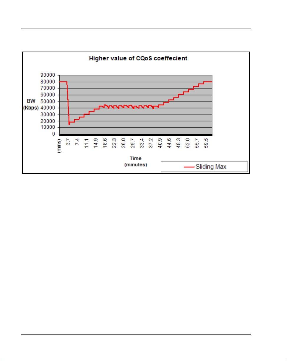
Page 74 of 258 Bandwidth Management
Figure 13
Effect of a higher CQoS Coefficient
Other configurable coefficients used in the calculation are the QoS
Coefficient (CQoS), QoS Response Time Increase (ZQRT), and QoS
Response Time Interval (ZQRTI). CQoS, Cr, Cd, Cpl, and Cj control the rate
of bandwidth decrease, while ZQRT and ZQRTI control the rate of
bandwidth increase.
The Call Admission Control (CAC) Validity Time Interval (CACVT) is used
to control the length of time that records from a Call Server are saved in the
Bandwidth Management table. If there have not been any calls between two
Call Servers within the configured time, the Call Server is removed from the
table. For example, if Call Server A has Call Server B in the table, and no call
has been placed between A and B for the CACVT time, then Call Server A
removes all Call Server B records in the table.
Limitations
Virtual Office IP Phones are not subject to bandwidth limitations. They may
not have the correct zone information configured. They can also be controlled
553-3001-207 Standard 2.00 January 2006
Page 75

by a Call Server that is not responsible for the particular zone. Thus,
bandwidth management is not possible for these phones.
Feature packaging
The Adaptive Network Bandwidth Management feature requires the
following packages:
• QoS Enhanced Reporting (PVQM) package 401
Note: Package 401, QoS Enhanced Reporting (PVQM), is required if
the R value from the Phase II IP Phones is to be reported and used in the
calculations.
• Call Admission Control (CAC) package 407
Configuration rules
The configuration rules for Adaptive Network Bandwidth Management are as
follows:
• Each main office Call Server in a network must have a unique non-zero
VPNI.
Bandwidth Management Page 75 of 258
• All branch offices associated with a particular main office must have the
same VPNI as the main office Call Server.
• All IP Phones (other than specific IP SoftPhone 2050s) and DSP
endpoints on a Call Server must be configured for the same zone.
• IP SoftPhone 2050s being used remotely must be configured for Zone 0.
• Branch office systems must tandem all calls through the main office Call
Server to allow bandwidth monitoring and control. In this case, the media
path is direct between the branch office and any point in the network.
• Trunk Route Optimization (TRO) must be disabled between the main
office Call Server and the SRG. In this case, the media path is direct
between the branch office and any point in the network.
• Adaptive Network Bandwidth Management parameters are configured
on the main office only and must not be configured at the branch offices.
Main Office Configuration for Survivable Remote Gateway 50 Configuration Guide
Page 76

Page 76 of 258 Bandwidth Management
Configuring Adaptive Network Bandwidth Management
The following is a summary of the tasks necessary to configure Adaptive
Network Bandwidth Management in the network.
1 Enable the Call Admission Control (CAC) package.
2 Configure CAC in Element Manager or LD 117:
a Configure the VPNI on the main office and branch offices.
b Configure both the main office and branch office zones at the main
office.
c Configure the branch office zone on the SRG.
d Configure the interzone and intrazone bandwidth limits at the main
office and SRG.
e Enable Adaptive Network Bandwidth Management for the zones on
the main office Call Server.
f If required, alter the Adaptive Network Bandwidth Management
parameters in keeping with the information in “Advanced
Configuration Notes” below.
3 Tandem the outbound branch office calls by configuring the NRS.
4 Tandem the inbound branch office calls by creating a dialing plan which
routes all calls destined for the branch office through the main office.
Advanced Configuration Notes
1 The default values for Cpl, Cj, Cd, Cr and CQos can be increased to
increase the response time for Sliding Maximum changes. However,
increasing them can cause the Sliding Maximum to temporarily decrease
to a lower value then necessary, resulting in the needless blocking of
interzone calls.
2 Increasing the value of ZQRT will increase the speed at which the
Sliding Maximum increases. The same effect can be achieved by
decreasing ZQRTI. However, changing these values can cause the
Sliding maximum to oscillate until the network degradation is removed.
3 It may be necessary to change the notification level (ZQNL) of the Call
Server so it can react to the QoS alarms. Use LD 117 to change this level.
553-3001-207 Standard 2.00 January 2006
Page 77

Bandwidth Management Page 77 of 258
Refer to Converging the Data Network with VoIP (553-3001-160) for
information on notification levels for alarms.
Configuration using Element Manager
Element Manager can be used to enable and configure the feature.
The zone must exist before it can be configured for Adaptive Network
Bandwidth Management. Refer to IP Peer Networking: Installation and
Configuration (553-3001-213) for instruction on how to create and configure
basic properties of the zone.
To configure the Adaptive Network Bandwidth Management feature, select a
zone on the Zones web page (see Figure 6 on page 61) and click Adaptive
Network Bandwidth Management and CAC. The Adaptive Network
Bandwidth Management and CAC web page opens, as shown in Figure 14
on page 78.
Note: Do not configure Adaptive Networks Bandwidth Management for
Zone 0 or Virtual Trunk zones.
Main Office Configuration for Survivable Remote Gateway 50 Configuration Guide
Page 78

Page 78 of 258 Bandwidth Management
Figure 14
Adaptive Network Bandwidth Management and CAC web page
If the Adaptive Network Bandwidth Management feature is enabled using the
Enable Call Admission Control feature (ZCAC) check box, then the other
parameters can be adjusted as required.
Table 5 on page 79 shows the fields in the Adaptive Network Bandwidth
Management and CAC web page, the field definitions, and their LD 117
command equivalent.
553-3001-207 Standard 2.00 January 2006
Page 79

Bandwidth Management Page 79 of 258
Table 5
Adaptive Network Bandwidth Management and CAC fields
Field Title Field Definition
LD 117
equivalents
Enable Call Admission
Control Feature (CAC)
QoS Response Time
Increase (ZQRT)
QoS Response Time Interval
(ZQRTI)
Warning Alarm Threshold
(ZQWAT)
Critical Alarm Threshold
(ZQUAT)
R Alarm Coefficient (CR) The R (Cr) coefficient is used to calculate
Packet Loss Alarm
Coefficient (CPL)
Delay Alarm Coefficient (CD) The Delay (Cd) coefficient is used to
Jitter Alarm Coefficient (CJ) The Jitter (Cj) coefficient is used to calculate
Control the CAC feature for the zone
• Enable (check box selected)
• disable (clear the check box)
Bandwidth limit increment, as a percentage
of the QoS factor for the zone
Time (in minutes) between bandwidth limit
increments
A QoS value, which is lower than this value,
but higher than the Critical (Unacceptable)
Alarm Threshold, triggers a Major Alarm.
A QoS value, which is lower than this value,
triggers an Unacceptable (Critical) Alarm.
the QoS value for the zone.
The Packet Loss (Cpl) coefficient is used to
calculate the QoS value for the zone.
calculate the QoS value for the zone.
the QoS value for the zone.
ENL ZCAC
DIS ZCAC
CHG ZQRT
CHG ZQRTI
CHG ZQWAT
CHG ZQUAT
CHG CR
CHG CPL
CHG CD
CHG CJ
Coefficient of QoS (CQoS) The Coefficient of QoS (CQoS) is used to
calculate the overall QoS value for the zone.
Recent Validity Time Interval
(CACVT)
Main Office Configuration for Survivable Remote Gateway 50 Configuration Guide
Amount of time (in hours) for zone-to-zone
record validity. Once this interval expires,
records for unused zones are purged from
the tables.
CHG CQOS
CHG CACVT
Page 80

Page 80 of 258 Bandwidth Management
Configuration using Command Line Interface
You can also configure the Adaptive Network Bandwidth Management
feature using LD 117.
LD 117 — Configure Adaptive Network Bandwidth Management. (Part 1 of 6)
Command Description
CHG CACVT <Zone> <Interval>
Configure the zone-to-zone record validity time interval, where:
• Zone = 1-255
• Interval = 1-(48)-255
CHG CD <Zone> <Cd>
Change the Cd coefficient in the formula that determines how quickly an alarm
reduces the Sliding Maximum bandwidth for the identified zone, where:
• Zone = 1-255
• Cd = Cd coefficient = 1-(50)-100
CHG CPL <Zone> <Cpl>
Change the Cpl coefficient in the formula that determines how quickly an
alarm reduces the Sliding Maximum bandwidth for the identified zone, where:
• Zone = 1-255
• Cpl = Cpl coefficient = 1-(50)-100
CHG CJ <Zone> <Jitter>
Change the Cj coefficient in the formula that determines how quickly an alarm
reduces the Sliding Maximum bandwidth for the identified zone, where:
• Zone = 1-255
• Jitter = Jitter coefficient = 1-(50)-100
553-3001-207 Standard 2.00 January 2006
Page 81

Bandwidth Management Page 81 of 258
LD 117 — Configure Adaptive Network Bandwidth Management. (Part 2 of 6)
Command Description
CHG CQOS <Zone> <QoS>
Change the QoS coefficient in the formula that determines how quickly an
alarm reduces the Sliding Maximum bandwidth for the identified zone, where:
• Zone = 1-255
• QoS = QoS coefficient = 1-(50)-100
CHG CR <Zone> <Cr>
Change the Cr coefficient in the formula that determines how quickly an alarm
reduces the Sliding Maximum bandwidth for the identified zone, where:
• Zone = 1-255
• Cr = Cr coefficient = 1-(50)-100
Main Office Configuration for Survivable Remote Gateway 50 Configuration Guide
Page 82

Page 82 of 258 Bandwidth Management
LD 117 — Configure Adaptive Network Bandwidth Management. (Part 3 of 6)
Command Description
CHG ZONE <zoneNumber> <intraZoneBandwidth> <intraZoneStrategy>
<interZoneBandwidth> <interZoneStrategy> [<zoneIntent> <zoneResourceType>]
Change the parameters of an existing zone, where:
• zoneNumber = 1-255
• intraZoneBandwidth = 1000000 (Mbit/s)
• intraZoneStrategy = intrazone preferred strategy
— Best Quality = BQ
— Best Bandwidth = BB
• interZoneBandwidth = 1000000 (Mbit/s)
• interZoneStrategy = intrazone preferred strategy
— Best Quality = BQ
— Best Bandwidth = BB
• zoneIntent = type of zone, where:
— MO = Main Office zone
— BMG = Branch Media Gateway (branch office) zone
— VTRK = Virtual Trunk zone
• zoneResourceType = resource intrazone preferred strategy
— shared DSP channels (default) = shared
— private DSP channels = private
Note: In CS 1000 Release 4.5, the zones that were described with BMG
designator stay with BMG one, all the other zones are provided with MO
designator. It is possible to update ZoneIntent using the CHG ZONE
command.
CHG ZQRT <Zone> <Incr>
Change ZQRT, which is Response time increase by percentage. It is used to
determine the increase to the Sliding Maximum for the identified zone, where:
• Zone = 1-255
• Incr = increase value in percentage = 1-(10)-100
553-3001-207 Standard 2.00 January 2006
Page 83

Bandwidth Management Page 83 of 258
LD 117 — Configure Adaptive Network Bandwidth Management. (Part 4 of 6)
Command Description
CHG ZQRTI <Zone> <Interval>
Change the QoS Response Time Interval while alarms are not coming, in
order to increase the Sliding Maximum for the identified zone, where:
• Zone = 1-255
• Interval = interval in minutes = 1-(5)-120
CHG ZQUAT <Zone> <Thres>
Change the QoS Unacceptable Alarm Threshold value for the identified zone,
where:
• Zone = 1-255
• Thres = threshold value = 1-(75)-99
Note: When the zone-to-zone QoS value drops below the threshold value,
the alarm is presented. When the zone-to-zone QoS value is greater than this
threshold value, this alarm is presented as being deactivated. This value must
be below the value of ZQWAT.
CHG ZQWAT <Zone> <Thres>
Change the QoS Warning Alarm Threshold value for the identified zone,
where:
• Zone = 1-255
• Thres = threshold value = 1-(85)-99
Note: When the zone-to-zone QoS value drops below the threshold value,
the alarm is presented. When the zone-to-zone QoS value is greater than this
threshold value, this alarm is presented as being deactivated. The value for
ZQWAT must be higher than the value of ZQUAT.
Main Office Configuration for Survivable Remote Gateway 50 Configuration Guide
Page 84

Page 84 of 258 Bandwidth Management
LD 117 — Configure Adaptive Network Bandwidth Management. (Part 5 of 6)
Command Description
CHG ZQNL <ZoneNumber> <level>
Change the Notification Level for the specified zone, where:
• Zone = 1-255
• Level = 0-(2)-4, where:
— Level 0 = All voice quality alarms are suppressed.
— Level 1 = All zone-based Unacceptable alarms.
— Level 2 = Allow all level 1 alarms PLUS zone-based Warning alarms.
— Level 3 = Allow all level 1 and 2 alarms PLUS per-call Unacceptable
alarms.
— Level 4 = Allow all level 1, 2, and 3 alarms PLUS per-call Warning
alarms.
NEW ZONE <zoneNumber> [<intraZoneBandwidth> <intraZoneStrategy>
<interZoneBandwidth> <interZoneStrategy> <zoneIntent> <zoneResourceType>]
• zoneNumber = 1-255
• intraZoneBandwidth = 1000000 (Mbit/s)
• intraZoneStrategy = BQ (Best Quality)
• interZoneBandwidth = 1000000 (Mbit/s)
• interZoneStrategy = intrazone preferred strategy
— Best Quality = BQ
— Best Bandwidth = BB
• zoneIntent = type of zone, where:
— MO = Main Office zone
— BMG = Branch Media Gateway (branch office) zone
— VTRK = Virtual Trunk zone
• zoneResourceType = resource intrazone preferred strategy
— shared DSP channels (default) = shared
— private DSP channels = private
553-3001-207 Standard 2.00 January 2006
Page 85

Bandwidth Management Page 85 of 258
LD 117 — Configure Adaptive Network Bandwidth Management. (Part 6 of 6)
Command Description
DIS ZCAC <Zone>
Disables the Call Admission Control (CAC) feature for the specified zone,
where:
• Zone = 1-255
Note: Disables the feature on a zone-by-zone basis.
ENL ZCAC <Zone>
Enables the Call Admission Control (CAC) feature for the specified zone,
where:
• Zone = 1-255
Note: Enables the feature on a zone-by-zone basis.
Maintenance commands
The Adaptive Network Bandwidth Management feature can be maintained
using Element Manager or LD 117.
Maintenance using Element Manager
The CAC parameters, intrazone statistics, and interzone statistics for one of
more zones are available in Element Manager from the Zones web page,
shown in Figure 6 on page 61. To view the intrazone or interzone statistics,
use Procedure 3 on page 63. To display the CAC parameters, follow the steps
in Procedure 4.
Procedure 4
Displaying CAC parameters for one or more zones
1 Select IP Telephony > Zones from the navigator.
The Zones web page opens (see Figure 6 on page 61).
Main Office Configuration for Survivable Remote Gateway 50 Configuration Guide
Page 86

Page 86 of 258 Bandwidth Management
2 Click Maintenance Commands for Zones (LD 117).
The Maintenance Commands for Zones web page opens, as shown in
Figure 7 on page 64. This page lists all the configured zones and their
intrazone statistics by default.
3 Select Print Adaptive Network Bandwidth Management and CAC
Parameters (PRT ZCAC) from the Action drop-down list.
4 Select a zone from the Zone Number drop-down list, by doing one of the
following:
•Select ALL to print statistics for all zones.
• Select a specific zone number to display statistics for a specific zone.
5 Click Submit.
The Maintenance Commands for Zones web page reopens, displaying
the statistics for the specified zone or zones. A blank field indicates that
that statistic is either not available or not applicable to that zone.
Figure 15 on page 87 shows an example of the CAC parameters for
sample Zone 3.
553-3001-207 Standard 2.00 January 2006
Page 87

Figure 15
Element Manager — CAC parameters
Bandwidth Management Page 87 of 258
End of Procedure
Main Office Configuration for Survivable Remote Gateway 50 Configuration Guide
Page 88

Page 88 of 258 Bandwidth Management
Maintenance using LD 117
The same information can be displayed using commands in LD 117.
LD 117 — Display Adaptive Network Bandwidth Management information
(Part 1 of 3)
Command Description
CLR CACR <nearZone> [<nearVPNI>] [<farZone>] [<farVPNI>]
Clear zone-to-zone record for near (VPNI-Zone) for far (VPNI-Zone), where:
• nearZone = 0-255
• nearVPNI = 1-16383
• farZone = 0-255
• farVPNI = 1-16383
PRT INTRAZONE [<zone>]
Print intrazone statistics for the identified zones, where:
• zone = ALL or 1-255
The output of this command displays the following information:
• Zone
• State = ENL/DIS
• Type = PRIVATE/SHARED
• Strategy = BB/BQ
• MO/VTRK/BMG = zoneIntent
• Bandwidth = Kbps
• Usage = Kbps
•Peak = %
Figure 16 on page 91 shows an example of the output for this command.
553-3001-207 Standard 2.00 January 2006
Page 89

Bandwidth Management Page 89 of 258
LD 117 — Display Adaptive Network Bandwidth Management information
(Part 2 of 3)
Command Description
PRT INTERZONE [<nearZone>] [<nearVPNI>] [<farZone>] [<farVPNI>]
Print interzone statistics for the specific VPNI zone; where:
• nearZone = ALL or 0-255
• nearVPNI = 1-16383
• farZone = 0-255
• farVPNI = 1-16383
The output of this command displays the following information:
• Near end Zone
• Near end VPNI
• Far end Zone
• Far end VPNI
• State = ENL/DIS
• Type = PRIVATE/SHARED
• Strategy = BB/BQ
• MO/VTRK/BMG = zoneIntent
• QoS factor = %
• Bandwidth configured = Kbps
• Sliding max = Kbps
• Usage = Kbps
• Peak = %
• Call = Cph
•Alarm = Aph
The report rows are grouped as:
• First row = summary bandwidth usage per near zone
• Next rows = bandwidth usage per near (VPNI- Zone) and far (VPNI Zone)
Figure 17 on page 92 shows an example of the output for this command.
Main Office Configuration for Survivable Remote Gateway 50 Configuration Guide
Page 90

Page 90 of 258 Bandwidth Management
LD 117 — Display Adaptive Network Bandwidth Management information
(Part 3 of 3)
Command Description
PRT ZCAC [<zone>]
Print CAC parameters for the specified zone, or for all zones, where:
• zone = ALL or 0-255
The output of this command displays the following information:
• Local ZONE = 0-255
• State = ENL/DIS
• CR = 1-100
•CPL = 1-100
• CD = 1-100
• CJ = 1-100
• CQOS = 1-100
• ZQRT = 1-100
• ZQRTI = 10-120
• ZQUAT = 1-99
• ZQWAT =1-99
• CACVT = 1-255
Sample outputs for PRT commands
Figure 16 on page 91 shows an example of the output of the PRT
INTRAZONE command. Figure 17 on page 92 shows an example of the
output of the PRT INTERZONE command.
553-3001-207 Standard 2.00 January 2006
Page 91

Bandwidth Management Page 91 of 258
Figure 16
Sample output for PRT INTRAZONE command
=> prt intrazone
_______________________________________________________________
|Zone|State| Type |Strategy|MO/ | Bandwidth | Usage | Peak |
| | | | |VTRK/| kbps | kbps | % |
| | | | |BMG | | | |
|----|-----|-------|--------|----|-----------|---------|------|
| 2| ENL |SHARED | BQ | MO| 10000| 190| 3 |
|-------------------------------------------------------------|
| 44| ENL |SHARED | BQ | BMG| 10000| 0| 1 |
|-------------------------------------------------------------|
Number of Zones configured = 2
Main Office Configuration for Survivable Remote Gateway 50 Configuration Guide
Page 92

Page 92 of 258 Bandwidth Management
Figure 17
Sample output for PRT INTERZONE command
=> prt interzone
|Near end |Far end |State| Type |Stra|MO/ |QoS|Bandwidth | Sliding | Usage |Peak| Calls | Alarm |
| | | | |tegy|BMG/|Fac|Configured | max | | | | |
| | | | | |VTRK|tor| | | | | | |
|----------|----------|-----|-------|----|----|---|-----------|---------|---------|----|---------|---------|
|Zone|VPNI |Zone|VPNI | | | | | % | kbps | kbps | kbps | % | Cph | Aph |
|----|-----|----|-----|-----|-------|----|----|---|-----------|---------|---------|----|---------|---------|
| 2| | | | ENL |SHARED | BB| MO| | 10000| | 78| 1| | |
|----------------------------------------------------------------------------------------------------------|
| 2| 1| 33| 1| ENL |SHARED | BB| MO|100| 10000| | 78| 1| 1| 0|
|----------------------------------------------------------------------------------------------------------|
| 33| | | | ENL |SHARED | BB| BMG| | 10000| | 78| 1| | |
553-3001-207 Standard 2.00 January 2006
|----------------------------------------------------------------------------------------------------------|
| 33| 1| 2| 1| ENL |SHARED | BB| BMG|100| 10000| | 78| 1| 1| 0|
|----------------------------------------------------------------------------------------------------------|
Number of Zones configured = 1
Note: The Far end and VPNI fields are displayed only when Adaptive Bandwidth Management is enabled in LD 117.
Page 93

Bandwidth Management Page 93 of 258
Tandem Bandwidth Management overview
In order for the main office to correctly keep track of all the bandwidth being
used to and from a branch office the call must be tandemed through the main
office. When calls are tandemed through the main office only the signaling is
tandemed, the actual voice bandwidth travels directly between the source and
destination.
Bandwidth utilization for the branch office is tracked at the main office and
can be displayed in LD 117 using the PRT INTERZONE command. In order
to provide the correct bandwidth utilization to the main office Call Server,
when a branch office is calling another node in the network, the calls must be
tandemed through the main office Call Server in both the inbound and
outbound direction.
Entering the main office Gateway endpoint identifier in the Tandem Endpoint
field for each branch office gateways configured on the NRS only provides
tandeming in the outbound direction from each branch office (from branch
office to main office).
In order to tandem calls through the main office in the inbound direction
(from main office to branch office), one must make use of the dialing plan
capabilities of the CS 1000 to first route the call to the main office. The main
office prepends a prefix to the dialed number and the number is routed to the
branch office.
Tandeming all branch office calls through the main office allows the main
office to keep track of the bandwidth being used at each branch office.
Application
This feature applies to the branch office and the Adaptive Bandwidth
Management feature. Specifically, it applies to calls made to and from the
branch office from either telephones registered locally at the branch office
(digital, analog [500/2500-type], and IP Phones) or trunks at the branch office
to another node in the network. It does not apply when using branch office IP
Phones that are registered with the main office (for example, Normal Mode).
Main Office Configuration for Survivable Remote Gateway 50 Configuration Guide
Page 94

Page 94 of 258 Bandwidth Management
Patch Number
A patch is required on the main office in order to invoke this feature. The
patch number is MPLR 20259.
Dialing Plan Overview
Depending upon the type of dialing plan used in the network (Coordinated
Dialing Plan [CDP], or Uniform Dialing Plan [UDP] or a combination of
both) the general idea is to have all calls that are terminating at a branch office
first dial a number that will get routed to the main office associated with that
branch office. The main office recognizes this number as belonging to the
branch office and appends a tandem prefix to this number using Digit
Manipulation Index (DMI). The main office then routes the call to the branch
office while accounting for the additional bandwidth used.
See Figure 18 for an example of a tandem call.
Figure 18
A call between two branch offices tandems through the main office
Figure 19 on page 95 shows a general legend for the figures in the following
section.
553-3001-207 Standard 2.00 January 2006
Page 95

Figure 19
General legend
Bandwidth Management Page 95 of 258
Main Office Configuration for Survivable Remote Gateway 50 Configuration Guide
Page 96

Page 96 of 258 Bandwidth Management
Network using Uniform Dialing Plan
The following section provides general network configuration for a network
using UDP only.
Figure 20 shows two or more main offices with their branch offices, within a
larger network. Callers within each main office/branch office “region” use
UDP to place calls between systems. Callers also use UDP to place calls
across the IP network to the other main office(s) and its (their) branch offices.
In a typical network, a full region uses a single Home Location Code
(HLOC). However, it is also possible, where the number of users requires it,
to have two or more codes, although using one for the main office and one for
each branch office is unlikely at best.
Figure 20
Scenario 1: UDP throughout the network
Common details
In general, if an HLOC is shared between two or more systems, the
provisioning at the main office gets more complex, unless all branch offices
share HLOCs with the main office. That is, if the main office has two or more
HLOCs, and one or more of these (but not necessarily the same one) is used
by every branch office, then provisioning is relatively straight forward.
553-3001-207 Standard 2.00 January 2006
Page 97

Table 6 describes the network configuration and the steps that a call takes
during its setup.
Table 6
Configuration details for the general case
Bandwidth Management Page 97 of 258
Call progress
Region
1, 2, 3 UDP used for all calls within the region.
1, 2, 3 UDP used for region to region calls.
1, 2, 3 Prefixes for branch offices for regular calls are
1 1 All branch offices are provisioned at the NRS to route
1 2 Main office sends all UDP calls to destinations that
1 3 Main office sends all UDP calls to destinations that
1 4 All branch offices delete the prefix and any LOC
steps
Configuration detail and call progress
during call setup
required for all branch offices. May have additional
prefixes for E-911 calls, if required, or may share
prefixes.
all outbound calls (from the branch office) through
the main office. (NRS tandem configuration).
are not its own branch office to the NRS with
unchanged dialled digits.
are its own branch office to the NRS with a specific
gateway prefix in front of the dialled digits.
codes, and terminate the calls. May be to a local set
or to a trunk.
2,3 Similar call setup steps take places for calls within
region 2 and 3.
Main Office Configuration for Survivable Remote Gateway 50 Configuration Guide
Page 98

Page 98 of 258 Bandwidth Management
Differences when every branch office HLOC is shared with the main office
Table 7 shows the configuration when the branch office HLOC is shared with
the main office.
Table 7
Provisioning details for this case
Region Provisioning detail
1 Provisioning on the main office requires parsing to only
“normal” LOC identification and HLOC deletion.
1 LOC values that are on branch offices may be provisioned as
extended LOCs (> 3 digit codes).
1 The DMI for the branch office “LOC” inserts a gateway routing
prefix in front of the number.
2,3 Similar configuration, as above, applies to regions 2 and 3.
Call between two branch offices associated with the same main office
The following scenarios describe calls between two branch offices that
belong to the same main office. the different scenarios described below vary
vary in the manner in which the HLOC is architected; branch offices have
same HLOC as the main office, branch offices have a different HLOC than
the main office and so on.
Every branch office HLOC is shared with the main office
In the following example, the HLOC of all the branch offices and the HLOC
of the main office are all the same. See Figure 21 on page 99.
553-3001-207 Standard 2.00 January 2006
Page 99

Bandwidth Management Page 99 of 258
Figure 21
Call flow for Scenario 1 - local call
1 The branch office user dials 6-395-3456. The system transmits 395-3456
to the NRS. The NRS checks its provisioning, and determines that all
calls are to be sent to the main office; it directs the call to the main office.
2 The branch office sends the call to 395-3456 to the main office.
3 The main office determines that this is LOC 39534, to another branch
office, with gateway routing prefix 552. The system inserts the prefix and
transmits 552-395-3456 to the NRS. The NRS checks its provisioning,
and determines that all calls to prefix 552 are to be sent to branch office
A2; it directs the call to the branch office.
4 The main office sends the call to 552-395-3456 to the branch office. The
branch office deletes the prefix and the HLOC, and rings set 3456.
Main Office Configuration for Survivable Remote Gateway 50 Configuration Guide
Page 100

Page 100 of 258 Bandwidth Management
No branch office HLOC is shared with the main office, but can be shared with another branch office
In this example, the HLOC of the branch offices are the same but the HLOC
of the main office is different. See Figure 22.
Figure 22
Call flow for Scenario 1 - local call
1 The branch office user dials 6-395-3456. The system transmits 395-3456
to the NRS. The NRS checks its provisioning, and determines that all
calls are to be sent to the main office; it directs the call to the main office.
2 The branch office sends the call to 395-3456 to the main office.
553-3001-207 Standard 2.00 January 2006
 Loading...