


Passport
Installation
Guide
241-5101-200


Passport 8250
Installation
Guide
Publication: 241-5101-200
Document status: Standard
Document version: R2.2
Document date: October 1999
Copyright © 1999 Nortel Networks.
All Rights Reserved.
Printed in Canada
NORTEL, NORTEL NETWORKS, the globemark design, the NORTEL NETWORKS corporate
logo, and PASSPORT are trademarks of Nortel Networks.


Publication history
October 1999
R2.2 Standard
Commercial availability.
5
Passport 8250 Installation Guide R2.2

6 Publication history
241-5101-200 R2.2

Contents
7
About this document 11
Who should read this guide 11
What you need to know 11
How this guide is organized 11
Conventions 12
Documentation conventions 12
Symbol conventions 13
Related documents 13
Passport documents 13
NMS documents 14
Nortel support services 14
Chapter 1
Passport 8250 15
Passport 8250 functions 15
Passport 8250 hardware 16
Board modules 17
Communication ports 18
Dual power supply modules 18
Fan module 18
Passport 8250 software 19
Software compatibility 19
Related documents 19
Passport documents 19
NMS documents 19
Passport 8250 Installation Guide R2.2

8 Contents
Chapter 2
Preparing for the hardware installation 21
Selecting an installation site 21
Unpacking the Passport 8250 shipment 22
Taking inventory of the Passport 8250 shipment 22
Getting the tools to mount the chassis in a rack 24
Chapter 3
Installing the Passport 8250 device 25
Mounting the chassis in a rack 25
Safety precautions 25
Mounting the Passport 8250 device on a 19” rack 26
Mounting the Passport 8250 device on a NEBS or ETSI rack 28
Connecting cables to the ports 29
Connecting the DS-1/E1 ports 29
Connecting the ethernet port 31
Connecting the serial port 32
Connecting the ATM uplink port 33
Connecting the dual power supply 33
Securing the cables to the rack 35
241-5101-200 R2.2
Chapter 4
Configuring the Passport 8250 for operations 37
Logging into the CLI 37
Starting the Passport 8250 device and logging into the CLI 37
Configuring the Passport 8250 device for remote access 38
Viewing the boot parameters 39
Setting the boot parameters 39
Configuring the clocking scheme 40
Setting the clocking scheme to External Primary 42
Setting the clocking scheme to ExternalSecondary 43
Setting the clocking scheme to External Primary Automatic
Switching 43
Setting the reference clock to internal 44

Contents 9
Appendix A
Replacing hardware 45
Replacing a power supply module 46
Replacing a board module 47
Passport 8250 board guidelines 49
Replacing the fan module 49
Appendix B
LEDs 51
Appendix C
Standards 55
Product safety standards 55
Electromagnetic compatibility standards 55
Telecom standards 56
Thermal, mechanical, and power standards 56
Regulatory information standards 56
Federal Communications Commission (FCC) 57
Industry Canada Notice - Equipment attachment limitation 57
Index 59
Passport 8250 Installation Guide R2.2

10 Contents
241-5101-200 R2.2

About this document
This document explains how to install the Passport 8250 device.
This document uses the terms DS-1/E1 and STM-1/OC-3. The term DS-1/E1
is for information that applies to both DS-1 and E1 interfaces. The term
STM-1/OC-3 is for information that applies to both STM-1 and OC-3 ports.
Wheninformationisfor a specificinterfaceor port, theindividual designation
is given.
Who should read this guide
You should read this document if you are responsible for performing the
following tasks:
• Installing the Passport 8250 device.
• Replacing hardware components.
What you need to know
You need to know the following information:
• ATM networking principles.
11
• Electrical and physical safety procedures and standards.
How this guide is organized
This guide is divided into the following sections:
• “Passport 8250” (page 15).
• “Preparing for the hardware installation” (page 21).
• “Installing the Passport 8250 device” (page 25).
• “Configuring the Passport 8250 for operations” (page 37).
Passport 8250 Installation Guide R2.2

12 About this document
• “Replacing hardware” (page 45).
• “LEDs” (page 51).
• “Standards” (page 55).
Conventions
There are documentation and symbol conventions used in this document.
Documentation conventions
There are a number of documentation conventions you should know about.
• nonproportional spaced plain type
• nonproportional spaced bold type
•[optional_parameter]
Nonproportional spaced plain type represents system generated text or
text that appears on your screen.
Nonproportional spaced bold type represents words that you should type
or that you should select on the screen.
241-5101-200 R2.2
Words in square brackets represent optional parameters. The command
can be entered with or without the words in the square brackets.
•<general_term>
Words in anglebracketsrepresent variableswhichareto be replacedwith
specific values.
• UPPERCASE, lowercase
Uppercase and lowercase letters in commands and parameters must be
matched exactly.
•|
This symbol separates items from which you may select one; for
example, ON|OFF indicates that you may specify ON or OFF.
• ...
Three dots in a command indicate that the parameter may be repeated
more than once in succession.
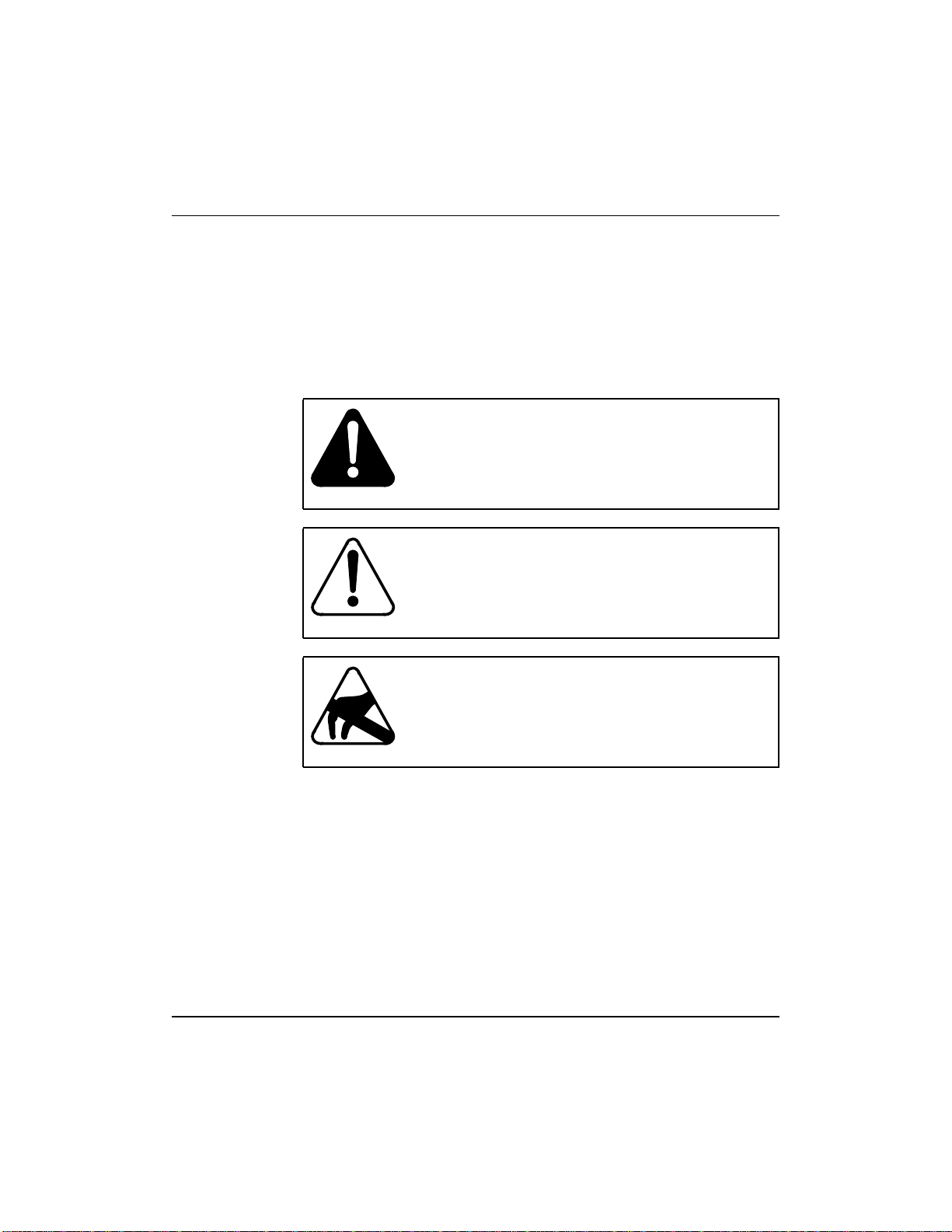
Symbol conventions
The following are samples of caution and warning conventions used in
this document:
About this document 13
WARNING
This warning informs you of risk of personal injury.
CAUTION
This caution informs you of risk of service interruption
or equipment damage.
Related documents
Documents relatedtothePassport 8250 are availablefrom Passport andNMS
documentation suites.
Passport documents
See NTP 241-5101-201, Passport 8250 Command Line Interface Guide for
information on how to monitor and configurethe Passport 8250 device using
the Passport 8250 command line interface (CLI).
CAUTION
This caution alerts you to the need to wear a grounded
antistatic wrist strap or equivalent protection to avoid
damaging electronic parts.
Passport 8250 Installation Guide R2.2

14 About this document
NMS documents
See the following NMS documents for information on how to monitor and
configure the Passport 8250 device using the NMS Passport 8250 tools,
integrating the Passport 8250 device into the NMS environment, and using
backup and restore:
• NTP 241-6001-028, NMS Passport 8250 Tools Guide.
• NTP 241-6001-110, NMS Passport 8250 Integration Guide.
• NTP 241-6001-807, NMS Backup and Restore User Guide.
Nortel support services
Forinformationon training,problemreporting, and technicalsupport,contact
your Nortel Networks customer representative.
241-5101-200 R2.2

Chapter 1
Passport 8250
This section describes the Passport 8250 device. Youcan view the following
topics in this section:
• “Passport 8250 functions” (page 15)
• “Passport 8250 hardware” (page 16)
• “Passport 8250 software” (page 19)
• “Related documents” (page 19)
Passport 8250 functions
The Passport 8250 is an Integrated Access MUX, a rugged,high-densityunit
that provides a seamless bridge between traditional voice networks and ATM
networks. The Passport 8250 multiplexes TDM traffic - voice, video, IP,
frame relay, X.25, and SNA - on DS-1/E1 trunks to OC-3c/STM-1 fiber
trunks (ATM over SONET/SDH). Using ATM Forum AAL1 circuit
emulationstandards,traditionalvoice networktraffic(dial-up Internet access,
modem data traffic, telephony, and more) is seamlessly transported over the
efficient, high-bandwidth ATM network. Deployed at either the service
provider setting or customer premises (campus,apartment building, or office
center, for example), the high-density unit supports up to 48 DS-1/E1 ports,
up to 336 DS-1s/E1s in a single frame.
15
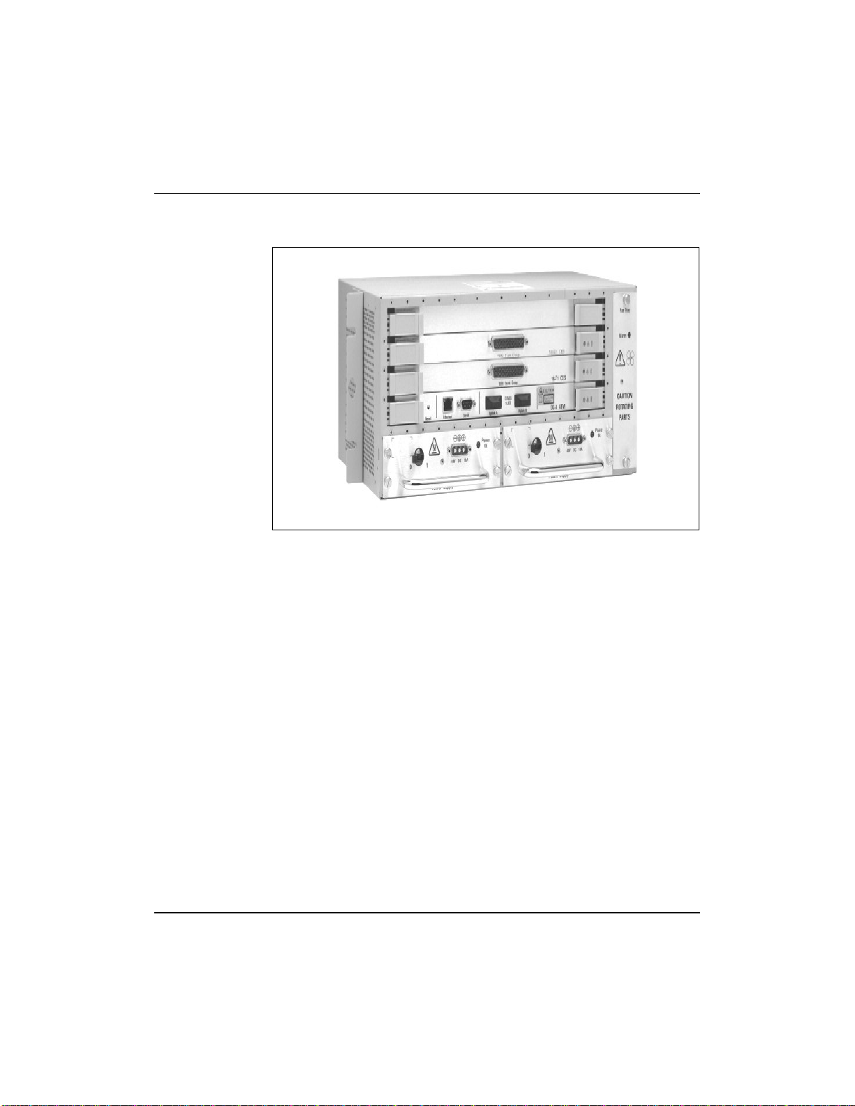
See “Passport 8250 device” (page 16) foranillustrationof the Passport 8250.
Passport 8250 Installation Guide R2.2
16 Chapter 1 Passport 8250
Figure 1
Passport 8250 device
The Passport 8250 can be used for the following applications:
• Providingmediumtohigh density DS-1 or E1 ingress to an ATMcarrier
network.
• Providing medium to high density DS-1 or E1 ingress to an ATM
wireless network.
• Acting as a traffic bridge between ATM network and TDM Trunks.
Passport 8250 hardware
The Passport 8250 device contains the following hardware components:
• Base chassis
• “Board modules” (page 17)
• “Communication ports” (page 18)
• “Dual power supply modules” (page 18)
• “Fan module” (page 18)
241-5101-200 R2.2
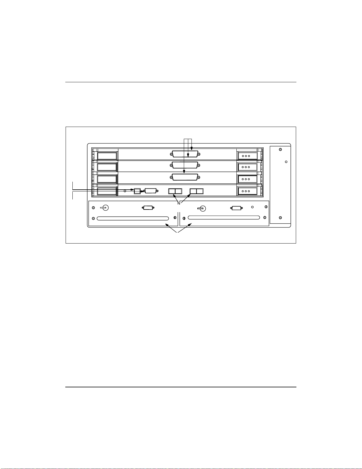
See “Passport 8250 front panel” (page 17) for an illustration of the hardware
components.
Figure 2
Passport 8250 front panel
Service board 3
Service board 2
Ethernet
port
Service board 1
Chapter 1 Passport 8250 17
DS-1/E1 ports
Fan
module
Network board
Serial
port
ATM uplink port
Dual power supply modules
Board modules
The Passport 8250 device has a field-replaceable network board and up to
three field-replaceable DS-1/E1 service boards.
Network board
The networkboardisasingle-mode or multi-mode integrated dual trunk. The
network board controls the Passport 8250 device and contains the
communication ports.
DS-1 and E1 service boards
The Passport 8250 device can hold one, two, or three DS-1 or E1 service
boards.Serviceboards send andreceive DS-1/E1signalsand convertbetween
ATM cells and DS-1/E1 traffic. Each service boardhas 16 physical DS-1/E1
ports.
Passport 8250 Installation Guide R2.2

18 Chapter 1 Passport 8250
Communication ports
The communication ports, which are locatedonthe network board, include a
serial port, ethernet port, and redundant ATM uplink port.
Serial port
The serial port connects the Passport 8250 device to a local host using a
RS-232 cable. Using a standard terminal emulation software application
running on the local host, you can directly access thecommandlineinterface
(CLI).
Use theserialportto configure the Passport8250device for operations before
the Passport 8250 device is connected to your network.
Ethernet port
The ethernet port connects the Passport 8250 device to a local area network
(LAN) using a RJ-45 cable.You can use a Telnet session on a remote host to
remotely access the CLI, provided the Passport 8250 device already has an
Internet protocol (IP) address.
Use theethernetportto configure the Passport8250devicewhile the Passport
8250 device is connected to your network and to communicate with other
devices within your network.
Dual power supply modules
Fan module
241-5101-200 R2.2
Redundant ATM uplink port
The ATM uplink port connects the Passport 8250 device to the ATM network
using a STM-1/OC-3 single-mode or multi-mode fiber optic cable. The ATM
uplink port has two physical connectors and one connector is configured as
the primary port that listens for incoming signals from the ATM network.
The Passport 8250 device uses two field-replaceable 10 amps, -10 V DC
power supply modules. Each power supply module has a 3w3-D connector
and independent power feed.
If a power supply module fails, the Passport 8250 device can operate
temporarilyusingonepower supplymoduleand one powersupplyfiller pack.
A field-replaceable fan module cools the internal components of the Passport
8250 device.

Passport 8250 software
You do not have to order software for the Passport 8250. The Passport 8250
comes preloaded with the operating system and the applications it needs.
Base trunking software is included with the integrated trunk/control card
(network board), and the CES software with the access modules (service
boards), so no service support is required.
You can use the Network Management System (NMS) software to manage
the Passport 8250 devices. For information on installing and configuring the
NMS software, see NTP
.
Guide
Software compatibility
Passport 8250 release 2.2 can be used with the following software:
• Passport software that is release 5.0 or higher.
• NMS software that is release 11.1 or higher.
Related documents
Documents relatedtothePassport 8250 are availablefrom Passport andNMS
documentation suites.
Chapter 1 Passport 8250 19
241-6001-110, NMS Passport 8250 Integration
Passport documents
See NTP 241-5101-201, Passport 8250 Command Line Interface Guide for
information on how to monitor and configurethe Passport 8250 device using
the Passport 8250 command line interface (CLI).
NMS documents
See the following NMS documents for information on how to monitor and
configure the Passport 8250 device using the NMS Passport 8250 tools,
integrating the Passport 8250 device into the NMS environment, and using
backup and restore:
• NTP 241-6001-028, NMS Passport 8250 Tools Guide.
• NTP 241-6001-110, NMS Passport 8250 Integration Guide.
• NTP 241-6001-807, NMS Backup and Restore User Guide.
Passport 8250 Installation Guide R2.2

20 Chapter 1 Passport 8250
241-5101-200 R2.2

Chapter 2
Preparing for the hardware installation
Thissectionprovidesthe followingproceduresfor preparing for installingthe
Passport 8250 device:
1 “Selecting an installation site” (page 21)
2 “Unpacking the Passport 8250 shipment” (page 22)
3 “Taking inventory of the Passport 8250 shipment” (page 22)
4 “Getting the tools to mount the chassis in a rack” (page 24)
Selecting an installation site
Select a site that meets the following requirements:
• Access to a 10 Base-T ethernet drop.
• Dry and dust-free area.
• Temperature between 0 and 50 C.
• Humidity does not exceed 85 percent.
21
• Power outlets meet power requirements and are within 1.8 meters (6 ft.)
of the installation location.
• Restricted access location, which is defined as:
— Access can only be gained by qualified service personnel with the
use of a special tool or lock and key or by users who have been
instructed in the reasons for the restrictions applied to the location
and know the security precautions that must be taken.
Passport 8250 Installation Guide R2.2

22 Chapter 2 Preparing for the hardware installation
— Access isthrough the use of a special tool, or lockand key, or other
means of security, and is controlledby the authority responsible for
the location.
CAUTION
Risk damage to the equipment
You risk damage to the equipment if the installation site
fails to meet all environmental considerations.
Unpacking the Passport 8250 shipment
Move the Passport 8250 package to the installation site to unpack the
shipment. If any equipment is damaged, contact your Nortel Networks
representative.
1 Cutthetapethat seals thetopflaps, taking carenottocut into thecontents
of the box, and fold back all four flaps.
2 Remove foam and any other packaging material from the topofthe unit.
3 Lift thePassport8250 unit from the box andplaceithorizontally on a flat
surface.
4 Unpack any other equipment shipped with the unit.
5 Clear the unpacking area of all debris.
Taking inventory of the Passport 8250 shipment
After you unpack the Passport 8250 shipment, take inventory of the items
using the “Inventorychecklist”(page 23) to ensure you received all the items
ordered. If you are missing an item, contact your Nortel Networks
representative.
Note: NMS software and documentation are not included in the
inventory checklist.
241-5101-200 R2.2

Chapter 2 Preparing for the hardware installation 23
Table 1
Inventory checklist
Item Options available Code #
Chassis One option available. A0748182
Fan module One option available. A0760931
DS-1/E1
cables
DS-1 interface cable assembly, 10m
DS-1 interface cable assembly, 20m
DS-1 interface cable assembly, 30m
DS-1 interface cable assembly, 40m
DS-1 interface cable assembly, 50m
A0763467
A0763473
A0781132
A0781133
A0781134
E1 interface cable assembly, 10m
E1 interface cable assembly, 20m
E1 interface cable assembly, 30m
E1 interface cable assembly, 40m
E1 interface cable assembly, 50m
Power supply
cables
Dual power
supply
Boards network card (OC-3, single-mode)
Rackmounting
kits
DC power cable assembly, 10m
DC power cable assembly, 20m
DC power cable assembly, 30m
DC power cable assembly, 40m
DC power cable assembly, 50m
5 v and 3.3 v DC power module (2 required)
Dummy power supply filler pack (optional)
network card (OC-3, multi-mode)
network card (STM-1, single-mode)
network card (STM-1, multi-mode)
1, 2 or 3 service card (DS-1)
1, 2 or 3 service card (E1)
dummy circuit card filler pack (required if
ordered less than 3 service cards)
19” rack mounting kit
NEBS rack mounting kit
ETSI rack mounting kit
A0781139
A0781140
A0781141
A0781142
A0781143
A0763481
A0781135
A0781136
A0781137
A0781138
A0761105
A0748191
A0768073
A0760934
A0760946
A0780321
A0760951
A0760950
A0748198
A0748199
A0748200
A0748201
Passport 8250 Installation Guide R2.2

24 Chapter 2 Preparing for the hardware installation
Getting the tools to mount the chassis in a rack
To mount the chassis in a rack, you will need one or more of the following
tools:
• 9.5 mm wide flat-bladed screwdriver for 19” or ETSI rack installation.
• 10 mm A/F nut driver for NEBS rack installation.
• Pozidrive screw driver suitable for a M4 screws for assembling the
mounting brackets to the chassis.
• Small flat-bladed screwdriver for securing the “D-type looking” screws.
241-5101-200 R2.2

Chapter 3
Installing the Passport 8250 device
This section provides the following procedures for installing the Passport
8250 device:
1 “Mounting the chassis in a rack” (page 25).
2 “Connecting cables to the ports” (page 29).
3 “Connecting the dual power supply” (page 33).
4 “Securing the cables to the rack” (page 35).
Mounting the chassis in a rack
The Passport 8250 device can be mounted on the following racks:
• 19 “ rack. For details, see “Mounting the Passport 8250 device on a 19”
rack” (page 26).
• New equipment building system (NEBS) rack. For details, see
“Mounting thePassport8250 device on aNEBSorETSI rack” (page 28).
• European Telecommunication Standards Institute (ETSI) rack. For
details, see “Mounting the Passport 8250 device on a NEBS or ETSI
rack” (page 28).
25
Safety precautions
Mount the Passport 8250 device using the following safey precautions:
• Do not place the device in direct sunlight, near warm air exhausts or
heaters.
• Do not place the device around water.
Passport 8250 Installation Guide R2.2

26 Chapter 3 Installing the Passport 8250 device
• Allow at least 2 inches of ventilation space on both sides of thedevice as
illustrated in “Ventilation space” (page 26).
• Do not block the air flow around the device with cables. For details, see
“Securing the cables to the rack” (page 35).
• Leave adequate space between units on a rack.
• Secure each device to the rack with appropriate mounting brackets.
Figure 3
Ventilation space
2 in
Air
inlet
Mounting the Passport 8250 device on a 19” rack
1 Locate the bracket mounting holes on each side of the chassis.
2 Using a Pozidrivescrew driver,attach19”mountingbrackets to each side
of the chassis.
See “Attaching mounting brackets to chassis” (page 27) for an illustration
of how to attach the mounting brackets.
3 Use two of the providedrackfixings to aid you in theinitial location of the
chassis within the rack.
4 Find the desired position for the chassis on the rack.
2 in
Air
exhaust
241-5101-200 R2.2
5 Using the four fixings provided, secure the unit to the rack.
See “Installing the chassis on a 19” rack” (page 27) for an illustration of
how to install the chassis on the rack.

Figure 4
Attaching mounting brackets to chassis
Figure 5
Installing the chassis on a 19” rack
Chapter 3 Installing the Passport 8250 device 27
Secure mounting
bracketstotheunit
using the fixing
holes indicated
Secure
the unit
to the
rack in
four
places
Allow a minimum of 2SU
(88.9mm)abovetheunitfor
cabling
Temporary
fixing for
installation
aid
Passport 8250 Installation Guide R2.2

28 Chapter 3 Installing the Passport 8250 device
Mounting the Passport 8250 device on a NEBS or ETSI rack
1 Locate the bracket mounting holes on each side of the chassis.
2 Attachthemountingbracketstoeach side ofthechassisusing a Pozidrive
screw driver.
See “Attaching mounting brackets to chassis” (page 27) for an illustration
of how to attach mounting brackets.
Note:
FortheNEBS rack,usetheNEBS mounting brackets.For theETSI
rack, use the ETSI mounting brackets.
3 Use two of the providedrackfixings to aid you in theinitial location of the
chassis within the rack.
4 Find the desired position for the chassis on the rack.
5 Using the four fixings provided, secure the unit to the rack.
See “Installing the chassis on a ETSI or NEBs rack” (page 28) for an
illustration of how to install the chassis on the rack.
Figure 6
Installing the chassis on a ETSI or NEBs rack
Secure
the unit
to the
rack in
four
places
Allow a minimum of 3SU
(75 mm) above the unit for
cabling
241-5101-200 R2.2
Temporary
fixing for
installation
aid

Chapter 3 Installing the Passport 8250 device 29
Connecting cables to the ports
You have to connect cables to the following ports:
• DS-1/E1 ports. For details on connecting cables, see “Connecting the
DS-1/E1 ports” (page 29).
• Ethernet port. For details on connecting cables, see “Connecting the
ethernet port” (page 31).
• Serial port. For details on connecting cables, see “Connecting the serial
port” (page 32)
• ATM uplink port. For details on connecting, see “Connecting the ATM
uplink port” (page 33).
Connecting the DS-1/E1 ports
WARNING
DS-1 / E1 port connections
Do not connect the DS-1/E1 ports to exposed plant wiring
or any other unprotected wiring which may be subjected to
electrical mains contact or atmospheric discharges.
Connect only to ports of other equipment designated as
SELV circuits as specified in the equipment safety
instructions.
1 Obtain the following equipment:
• ForeachDS-1/E1 port, twisted pair highdensitycablewith male DB-
78 connector. The AMP high density D subminiature 216158-1 or
748368-1 is the recommended connector.
• DS-1/E1 equipment, such as a PBX.
• Patch panel (optional).
Note:
Whenyouorderthe cable, pleaseensurethatthecable numbering
starts with number one.
2 Connect the DS-1/E1 cables to the DS-1/E1 ports located on the front
panel of the Passport 8250 device.
The DS-1/E1 ports are femaleDB-78highdensityconnectors.For details
on the DS-1/E1 pin assignments, see “DS-1/E1 pin assignment”
(page 30).
Passport 8250 Installation Guide R2.2

30 Chapter 3 Installing the Passport 8250 device
3 Connect the other end of the DS-1/E1 cable to the far end.
Table 2
DS-1/E1 pin assignment
Description Signal Pin Pin Signal Description
transmit tip port 0 TXTIPC0 1 40 RXTIPCO receive tip port 0
transmit tip port 1 TXTIPC1 2 41 RXTIPC1 receive tip port 1
transmit tip port 2 TXTIPC2 3 42 RXTIPC2 receive tip port 2
transmit tip port 3 TXTIPC3 4 43 RXTIPC3 receive tip port 3
transmit tip port 4 TXTIPC4 5 44 RXTIPC4 receive tip port 4
transmit tip port 5 TXTIPC5 6 45 RXTIPC5 receive tip port 5
transmit tip port 6 TXTIPC6 7 46 RXTIPC6 receive tip port 6
transmit tip port 7 TXTIPC7 8 47 RXTIPC7 receive tip port 7
transmit tip port 8 TXTIPC8 9 48 RXTIPC8 receive tip port 8
transmit tip port 9 TXTIPC9 10 49 RXTIPC9 receive tip port 9
transmit tip port 10 TXTIPC10 11 50 RXTIPC10 receive tip port 10
transmit tip port 11 TXTIPC11 12 51 RXTIPC11 receive tip port 11
transmit tip port 12 TXTIPC12 13 52 RXTIPC12 receive tip port 12
transmit tip port 13 TXTIPC13 14 53 RXTIPC13 receive tip port 13
transmit tip port 14 TXTIPC14 15 54 RXTIPC14 receive tip port 14
transmit tip port 15 TXTIPC15 16 55 RXTIPC15 receive tip port 15
not connected 17 56 not connected
not connected 18 57 not connected
not connected 19 58 not connected
not connected 20 59 not connected
transmit ring port 0 TXRINGC0 21 60 RXRINGC0 receive ring port 0
transmit ring port 1 TXRINGC1 22 61 RXRINGC1 receive ring port 1
transmit ring port 2 TXRINGC2 23 62 RXRINGC2 receive ring port 2
(Sheet 1 of 2)
241-5101-200 R2.2

Chapter 3 Installing the Passport 8250 device 31
Table 2 (continued)
DS-1/E1 pin assignment
Description Signal Pin Pin Signal Description
transmit ring port 3 TXRINGC3 24 63 RXRINGC3 receive ring port 3
transmit ring port 4 TXRINGC4 25 64 RXRINGC4 receive ring port 4
transmit ring port 5 TXRINGC5 26 65 RXRINGC5 receive ring port 5
transmit ring port 6 TXRINGC6 27 66 RXRINGC6 receive ring port 6
transmit ring port 7 TXRINGC7 28 67 RXRINGC7 receive ring port 7
transmit ring port 8 TXRINGC8 29 68 RXRINGC8 receive ring port 8
transmit ring port 9 TXRINGC9 30 69 RXRINGC9 receive ring port 9
transmit ring port 10 TXRINGC10 31 70 RXRINGC10 receive ring port 10
transmit ring port 11 TXRINGC11 32 71 RXRINGC11 receive ring port 11
transmit ring port 12 TXRINGC12 33 72 RXRINGC12 receive ring port 12
transmit ring port 13 TXRINGC13 34 73 RXRINGC13 receive ring port 13
transmit ring port 14 TXRINGC14 35 74 RXRINGC14 receive ring port 14
transmit ring port 15 TXRINGC15 36 75 RXRINGC15 receive ring port 15
not connected 37 76 not connected
not connected 38 77 not connected
not connected 39 78 not connected
(Sheet 2 of 2)
Connecting the ethernet port
1 Obtain the following equipment:
• Aregular RJ-45 ethernet cable with a male DB-8 connector and a 10
Base-T ethernet drop for a connection to a work station.
• A cross-connect RJ-45 ethernet cable with a male DB-8 connector
for a connection to a 10 Base-T ethernet drop.
2 Connect the RJ-45 cabletotheethernet port located on the front panel of
the Passport 8250 device.
The ethernet port is a female DB-8 RJ-45 connector.
Passport 8250 Installation Guide R2.2

32 Chapter 3 Installing the Passport 8250 device
3 Connect the other end of the RJ-45cabletoa10Base-Tethernetdropor
work station.
Connecting the serial port
1 Obtain the following equipment:
• VT-100 terminal or a PC with terminal-emulation software
• Null modem RS-232 cable with a male DTE DB-9 connector with the
connector ontheotherendofthe cable appropriate for theserialport
on the PC or terminal (most terminals or PCs use a male, DB-25
connector).
2 Connect the RS-232cable to the serial port located on the front panel of
the Passport 8250 device.
The serial port is a female DB-9 RS-232connector configured asa data
termination equipment (DTE).
3 Connect the other end of the RS-232 cable to the serial port on the
VT-100 terminal or PC.
4 Ensure that the serial ports on the Passport 8250 device and the local
host are configured as follows:
• bits per second: 9600
• data bits: 8
241-5101-200 R2.2
• parity: none
• stop bit: 1
• control flow: none

Chapter 3 Installing the Passport 8250 device 33
Connecting the ATM uplink port
WARNING
Network uplink cards A0768073 and A0760946 contain
class 1 laser and network uplink cards A0760934 and
A0780321 contain class 1 LED
Class 1 designatedproducts are safe toview under normal
conditions. Output of the device is invisible to the human
eye. Avoid staring into the ends of fiber optical cables or
connectors.
For class 1 laser,themaximumoutputpoweris-8dBmand
the emission wavelength is 1310nm. For class 1 LED, the
maximum output power is -14dBm and the emission
wavelength is 1310nm.
1 Obtain the following equipment:
• Multi-modefiberopticcables with SC connectors withatypicalrange
of 0-2 km
• Single-mode fiber optic cables with SC connectors with a typical
range of 0-15 km
2 Connect the STM-1or OC-3 single-mode ormulti-mode fiber optic cable
to port A and port B located on the front panel of the Passport 8250
device.
The port A and port B are female SC connectors.
3 Connect the other end of the fiber optic cable to the far end.
Connecting the dual power supply
See “Dual power supply” (page 34) for an illustration of the two power
supply modules.
Passport 8250 Installation Guide R2.2

34 Chapter 3 Installing the Passport 8250 device
Figure 7
Dual power supply
Power supply 1
1 Obtain the following equipment:
2 Ifthepowersupply module is suppliedseparately,insert thepowersupply
3 Locate the 3W3-D type input connector on the power supply module.
Power supply breaker
Power supply 2
3W3-D connector
CAUTION
Antistatic protection
Before handling the power supply, make sure that the
power is off and you are wearing antistatic protection.
• A-48vDC power supplycablewith3W3-D connector foreachpower
supply module.
• Antistatic protection, such as an antistatic glove.
module into an empty power supply slot and tighten the four securing
screws with a screw driver.
Verify that the securing screws cannot be loosened by hand.
241-5101-200 R2.2

Chapter 3 Installing the Passport 8250 device 35
The central contact is designated as the chassis ground.
Centre contact of the
power input connector
is designated for the
product earth.
4 Connect the -48v power supply cable with the male 3W3-D connector to
the female 3W3-D connector.
Tighten the screwsonthe3W3-Dconnectorandverifythattheconnector
is secured to chassis of power supply.
5 Repeat steps 1 to 4 for the other power supply module.
6 Connect the power supply modules with the recommended wiring
harness to the branch circuit of the power distribution system.
7 Configure the electrical branch circuitprovidingpowertothePassport as
follows:
• A double-pole disconnect switch whichisolates both the power feed
and return conductors. A separate switch shallbe provided for each
separate power feed to the equipment.
• The branch circuit protection shall be located in the ungrounded
conductor and be rated at no larger than 30A.
• Theequipmentprotectivegroundingconductor shall be permanently
connected to the protective earthing conductor in the building
electrical distribution system.
8 Connect to the power unit with the recommended wiring harness to the
branch circuit of the power distribution system.
9 Apply branch circuit power.
Securing the cables to the rack
Do not block air vents, field-replaceable modules, and LEDs with cables
when connecting the cables to the ports.
Passport 8250 Installation Guide R2.2

36 Chapter 3 Installing the Passport 8250 device
Exit and secure all cables to the left as illustrated in “Cables left of chassis”
(page 36) or underneath the chassis as illustrated in “Cables underneath
chassis” (page 36).
Figure 8
Cables left of chassis
Figure 9
Cables underneath chassis
241-5101-200 R2.2

Chapter 4
Configuring the Passport 8250 for operations
This section provides the following procedures for configuring the Passport
8250 device for the operations:
1 “Logging into the CLI” (page 37)
2 “Configuring the Passport 8250 device for remote access” (page 38)
3 “Configuring the clocking scheme” (page 40).
Logging into the CLI
The first time you log into the CLI, you need to do the following:
• Access the CLI using a terminal emulation device that is directly
connected to the Passport 8250 device. The terminal emulation device
must have a standard terminal emulation software.
• Create a password. The password is used for CLI sessions, Telnet
sessions, and FTP sessions.
Note: The userid for CLI sessions, Telnet sessions, and FTP sessions is
admin.
37
Starting the Passport 8250 device and logging into the CLI
1 Start a hyperterminal session on the local host.
2 Start the Passport 8250 device:
Passport 8250 Installation Guide R2.2

38 Chapter 4 Configuring the Passport 8250 for operations
a. For each power supply module, turn the power supply breaker to ON.
Breaker is off. Turn to on.
The LEDs on each power supply module is on.
Text is displayed on the hyperterminal screen.
3 From the hyperterminal session, stop the Passport 8250 device from
starting-up:
a. Press the return key within three seconds of the following text
displaying on the screen:
PRESS ANY KEY TO CONFIGURE BOOT PARAMETERS.
4 From the hyperterminal session, log into the CLI:
a. Press the return key until the username prompt is displayed on the
screen.
b. At the username prompt, type admin.
administhepermanentuseridfor CLI sessions,Telnetsessions,and
FTP sessions.
c. At the password prompt, type a password between 8 and 12
characters.
Configuring the Passport 8250 device for remote access
Before you can Telnet to the CLI, FTP to the flash file system, and start the
Passport 8250 device from a remote workstation, configure the boot
parameters for the Passport 8250 device using the bootconfig command.
The syntax of the bootconfig command is:
bootconfig [set]
where
[set] modifies one or more boot parameters
241-5101-200 R2.2

Chapter 4 Configuring the Passport 8250 for operations 39
See “Boot command parameters” (page 39) for the boot parameters you need
to configure.
Table 3
Boot command parameters
boot parameter Description
file name The full pathname of the file loaded during a network
boot.
inet on ethernet The IP address ofthePassport8250device with subnet
mask.
inet on backplane This field is not used.
host inet The IP address of the remote host.
gateway inet The IP address of the gateway node. Required if the
remote host is on a different network.
user The FTP userid of the remote host.
ftp password TheFTPpasswordof the remotehostthePassport 8250
device uses during a network boot.
Viewing the boot parameters
To display the existing boot parameters, Type the bootconfig command
without the [set] parameter.
1 At the CLI prompt, type bootconfig:
bootconfig
The boot parameters are displayed.
Setting the boot parameters
1 At the CLI prompt, type bootconfig set:
bootconfig set
The boot parameters are displayed.
2 For file name, type the fullpathname of the file the Passport8250 device
will load during a network boot.
3 Forinetonethernet, typetheIPaddressofthe Passport 8250 device with
the subnet mask.
Passport 8250 Installation Guide R2.2

40 Chapter 4 Configuring the Passport 8250 for operations
4 For host inet, type the IP address of the remote host.
5 If the remote host is on a different network, type the IP address of the
gateway node at the gateway inet prompt.
6 For user, type the FTP userid of the remote host.
7 For ftp password, type the FTP password of the remote host.
8 Reboot the Passport 8250 device to save the boot parameters.
reboot
Note:
After restarting the Passport 8250, you can log into the CLI only
after ****BOOT COMPLETE, SYSTEM IS READY**** is displayed.
Configuring the clocking scheme
To configure the clocking scheme for the Passport 8250 device, select the
source for thereference clock, and, if applicable, select the switching option
using the clockconfig command.
The switching methods are the following:
• Internal. The clocking scheme is derivedfrom the Passport 8250 device.
• External. The clocking schemeis derivedfromthe ATM network off the
ATM uplink port or aT1/E1 port on the Passport 8250. Select oneof the
following switching options:
241-5101-200 R2.2
— Fixed. The clocking scheme is fixed permanently to the primary
port. If there is a problem with theprimaryport,you need to change
to the secondary port using the clockconfig command.
— Automatic switching. The clocking scheme is temporarily fixed to
theprimaryport.The Passport8250automaticallyswitches from the
primary port to the secondary port and, if needed,switchesfromthe
secondary port to internal.
Note: We recommend that you select the device with the lower stratum
clock as the clock source. The Passport 8250 has a stratum 4 clock.
The syntax of the clockconfig command is:
clockconfig [set]

Chapter 4 Configuring the Passport 8250 for operations 41
where
[set] configures the clocking scheme for the Passport 8250 device.
For details on the clockconfig parameters, see “Clockconfig command
parameters” (page 41).
Table 4
Clockconfig command parameters
Parameter Values Definition
External Primary
Board Number
0 = network board (default)
1 = service board in slot 1
2 = service board in slot 2
3 = service board in slot 3
The board that
contains the
primary port.
External Primary
Port Number
External Secondary
Board Number
External Secondary
Port Number
(Sheet 1 of 2)
When External Primary Board
Number is 1, 2, or 3, 1 to 16 for
the T1/E1 ports.
When External Primary Board
Number is 0, 3 for the ATM
uplink port (default).
The same as the External
Primary Board Number.
The same as the External
Primary Port Number.
The primary port.
The board that
contains the
secondary port.
The secondary
port.
Passport 8250 Installation Guide R2.2

42 Chapter 4 Configuring the Passport 8250 for operations
Table 4 (continued)
Clockconfig command parameters
Parameter Values Definition
Admin Reference
Clock Source
0 = Internal = The clock is
derived from the Passport
8250.
1 = External Primary = clock
derived from the primary port.
2=External Primary Automatic
Switching=Clockderived from
the primary port. Switch to
secondary port if problem with
secondary port.
3 = External Secondary =
Clock is derived from the
secondary port.
The clock source.
Operational
Reference Clock
Source
(Sheet 2 of 2)
Internal (default),
ExternalPrimary, and
ExternalSecondary.
The current clock
source.
Setting the clocking scheme to External Primary
1 Display the clockconfig parameters:
clockconfig [set]
2 For External Primary Board Number, enter a board number.
3 For External Primary Port Number, enter a port number.
4 For External Secondary BoardNumber, press enter toaccept the default
value and move to the next field.
5 For External Secondary Port Number, press enter to accept the default
value and move to the next field.
6 For Admin Reference Clock Source, enter 1 for ExternalPrimary:
Admin Reference Clock Source: Internal 1
Example
The following is an example of setting port 10 on service board 2 as the
primary port. The clocking scheme is set to ExternalPrimary.
241-5101-200 R2.2

Chapter 4 Configuring the Passport 8250 for operations 43
[E1-1]: clockconfig set
External Primary Board Number (0 - 3) = 0 2
External Primary Port Number (1 - 16) = 3 10
External Secondary Board Number = 0
External Secondary Port Number = 3
Admin Reference Clock Source: Internal 1
Setting the clocking scheme to ExternalSecondary
1 Display the clockconfig parameters:
clockconfig set
2 For External Primary Board Number, press enter to accept the default
value and move to the next field.
3 ForExternalPrimary PortNumber, press entertoacceptthedefault value
and move to the next field.
4 For External Secondary Board Number, enter a board number.
5 For External Secondary Port Number, enter a port number.
6 For Admin Reference Clock Source, enter 3 for ExternalSecondary:
Admin Reference Clock Source: ExternalPrimary 3
Example
The following is an example of switching from the primary port
configured in “Setting the clocking scheme to External Primary”
(page 42) to a secondary port. The secondary port is the default ATM
uplink port on the network board. The clocking scheme is
ExternalSecondary.
[E1-1]: clockconfig set
External Primary Board Number (0 - 3) = 2
External Primary Port Number (1 - 16) = 10
External Secondary Board Number = 0
External Secondary Port Number = 3
Admin Reference Clock Source: ExternalPrimary 3
Setting the clocking scheme to External Primary Automatic
Switching
1 Display the clockconfig parameters:
Passport 8250 Installation Guide R2.2

44 Chapter 4 Configuring the Passport 8250 for operations
clockconfig [set]
2 For External Primary Board Number, enter a board number.
3 For External Primary Port Number, enter a port number.
4 For External Secondary Board Number, enter a board number.
5 For External Secondary Port Number, enter a port number.
6 For Admin Reference Clock Source, enter 2 for
ExternalPrimaryAutomaticSwitchOn:
Admin Reference Clock Source: Internal 2
Example
The following is example of setting the clocking scheme to
ExternalPrimaryAutomaticSwitchOn. The primary port is the ATM
uplink port on the network board and the secondary port is port 16 on
service board 3.
[E1-1]: clockconfig set
External Primary Board Number (0 - 3) = 0
External Primary Port Number (1 - 16) = 3
External Secondary Board Number = 0 3
External Secondary Port Number = 3 16
Admin Reference Clock Source: Internal 2
Setting the reference clock to internal
241-5101-200 R2.2
1 Display the clockconfig parameters:
clockconfig [set]
2 ForExternal Primary Board Number, press enter to movetothenextfield.
3 For External Secondary Port Number, press enter to move to the next
field.
4 For External Secondary Board Number, press enter to move to the next
field.
5 For External Secondary Port Number, press enter to move to the next
field.
6 For Admin Reference Clock Source, enter 1 for internal.

Appendix A
Replacing hardware
Thissectionprovidesinstructions on howtoreplace hardware componentson
the Passport 8250 device. You can view the following procedures in this
section:
• “Replacing a power supply module” (page 46)
• “Replacing a board module” (page 47)
• “Replacing the fan module” (page 49)
Figure 10
Field-replaceable modules
45
Fan
module
Power supply modules
Board
modules
Passport 8250 Installation Guide R2.2

46 Appendix A Replacing hardware
Replacing a power supply module
The Passport 8250 device is powered by two power supply modules. If a
power supply module stops operating, you need to immediately replace it
with a dummy power supply filler pack to ensure proper cooling and airflow.
You also need to contact your Nortel Networks representative to order a new
power supply module.
WARNING
Removing a power supply module
Turn the power off and let the unit cool before removing a
power supply module.
1 For each power supply module, set the power supply breaker to off.
Breaker is off
241-5101-200 R2.2
2 Disconnect the power feed at the power distribution source.
3 Using a screwdriver, loosen the four securing screws on the sides the
power supply module.

Appendix A Replacing hardware 47
4 Slide the power supply module or dummy power supply filler pack out of
the slot.
5 Insert the new power supply module ordummy power supply filler pack
into the empty power supply slot.
6 Using a screw driver, tighten the four securing screws on the sides the
powersupplymodule. Verify thatthesecuring screwscannotbeloosened
by hand.
7 For each power supply module, set the power supply breakers to on.
8 If you inserted a new power supply module, confirm that the power
supply LED is to off.
If you inserted a dummy power supply filler pack, contact FLS
immediately to order a new power supply module.
Replacing a board module
The Passport 8250 is equipped with 4 board slots, one slot for the network
board and 3 slots for the service boards. See “Board slots” (page 48) for an
illustration of the slots. If the Passport 8250 device has less than three service
boards, dummy circuit card fillerpacksare needed for the empty board slots.
Passport 8250 Installation Guide R2.2

48 Appendix A Replacing hardware
Figure 11
Board slots
Service
board slot 1
Service
board slot 2
Service
board slot 3
Network boardslot 0
1 For each power supply module, set the power supply breaker to off.
Breaker is off
241-5101-200 R2.2
2 Flip the lock hatch at each end of the circuit board slot open.
3 Slide the network board or service board out of the circuit board slot.
4 Remove the new network board or service board from the package.
5 Insert the newnetworkboard or service board into theemptycircuitboard
slot.
6 Snap the lock hatches at the ends of the circuit board slot close.
7
For each power supply module, set the power supply breakers to on.

Passport 8250 board guidelines
Use caution when handling, storing, and transporting circuit boards. Follow
these guidelines:
• Do not stack or store boards without first replacing them in their
antistatic material and shipping material.
• Do not to damage any parts when inserting the boards into packages.
• Do not store boards in areas where the relative humidity can exceed 85
percent or temperature can exceed 70 C.
• Handle boards by the faceplate. Do not touch electrical connections,
pins, and soldered surfaces.
• Do not handle boards unless you are using appropriate antistatic
protections such as an antistatic wrist strap. It is recommended that you
use conductive carpet, conductive shoes, or heel grounders.
Replacing the fan module
If the fan module malfunctions,contact your Nortel Networks representative
to order a new fan module.
Appendix A Replacing hardware 49
WARNING
Rotating fan
Do not touch the fans immediately after removing the fan
tray.The fans may continue to rotate several seconds after
being removed.
1 For each power supply module, turn the power supply breaker to off.
Breaker is off
2
Loosen the two securing screws on the fan module.
3 Slide the fan tray out of the fan module slot.
Passport 8250 Installation Guide R2.2

50 Appendix A Replacing hardware
The fans continue to rotate for a few seconds.
4 Remove the new fan module from the package.
5 Insert the new fan module into the empty fan module slot.
6 Tighten the two securing screws on the fan module.
For each power supply module, turn the power supply breakers to on.
7
8 Confirm that the fan LED is off.
241-5101-200 R2.2

Appendix B
LEDs
The LEDs located on the front panel of the Passport 8250 device. See
“Passport 8250 LEDS” (page 52) for an illustration of the LEDs and “LEDs
description” (page 53) for a description of the LEDs on the illustration.
51
Passport 8250 Installation Guide R2.2

52 Appendix B LEDs
Figure 12
Passport 8250 LEDS
Service boards
Network board
5
Power supply 1 Power supply 2
1 2 3
876
Fan module
4
5
241-5101-200 R2.2

Appendix B LEDs 53
Table 5
LEDs description
Item color Description
1 green on = system initialized and software loaded
2 red on = All provisioned CES connections not working on
the service board
3 amber on = at least one, but not all, provisioned CES
connection does not work on the service board
4 Red on = fan failure
5 green on = power available for power supply module
6 green on = system initialized and software loaded
7 red on = problem with physical connection of OC-3/STM-1
cable to OC-3/STM-1 port
8 amber on = fault recorded in the fault log
For details on the fault log, see NTP 241-5101-201,
Passport 8250 Command Line Interface Guide
.
Passport 8250 Installation Guide R2.2

54 Appendix B LEDs
241-5101-200 R2.2

Appendix C
Standards
This section describes the standards the Passport 8250 device meets. You can
view the following topics in this section:
• “Product safety standards” (page 55)
• “Electromagnetic compatibility standards” (page 55)
• “Telecom standards” (page 56)
• “Thermal, mechanical, and power standards” (page 56)
• “Regulatory information standards” (page 56)
Product safety standards
The Passport 8250 device meets the following product safety standards:
• UL 1950, ed.3, 1995 (US)
• CSA C22.2 No. 950-M95 (Canada)
• EN 60950, 2nd Ed., 3rd Amt (EU)
55
• FDA 21 CFR (laser safety USA)
• EN60825-1, EN60825-2 (laser safety EU)
• Bellcore GR-1089-CORE
Electromagnetic compatibility standards
The Passport 8250 device meets the following electromagnetic compatibility
standards:
• Unintentional Radiator (Emission)
Passport 8250 Installation Guide R2.2

56 Appendix C Standards
— FCC Part 15, Class A (USA)
— ICES-003, Class A (Canada)
— EN 55022, Class A (Europe)
• Immunity, ESD, EFT (EU)
— EN50082-1
— EN300 386-2
— Bellcore GR-1089-CORE
Telecom standards
The Passport 8250 device meets the following telecom standards:
• FCC Pt 68 (US)
• IC CS-03, Issue 7 (Canada)
• TBR 13
• CTR 12
Thermal, mechanical, and power standards
The Passport 8250 device meets the following thermal, mechanical, and
power standards:
• NEBS, GR-63-CORE level 3, airborne contaminants and descending
temperature ramp excluded
Regulatory information standards
The Passport 8250 device meets the following regulatory information
standards:
• “Federal Communications Commission (FCC)” (page 57)
• “Industry Canada Notice - Equipment attachment limitation” (page 57)
241-5101-200 R2.2

Appendix C Standards 57
Federal Communications Commission (FCC)
The Passport 8250 device complies with Part 68 of the FCC rules.Onthe top
of this equipmentis a label that contains, among other information, the FCC
registration. If requested, thisinformation must be provided to the telephone
company.
The Passport 8250 uses the following standard connections and codes:
• Service Order Code: 6.0F
• Facility Interface Code: 04DU9-BN, 04DU9-DN, 04DU9-KN, 04DU9ISN
If the equipment causes harm to the telephone network, the telephone
company will notify you in advance that temporarily discontinuance of
service may be required. Butif advanced notice isn’t practical, the telephone
company will notify the customer as soon as possible. Also you will be
advised of your right to file a complaint with the FSS if you believe it is
necessary.
The telephone company may make changes in its facilities, equipment,
operations or procedures that could affect the operation of the equipment. If
this happens, the telephone company will provide advance notice in order for
you to make necessary modifications to maintain uninterrupted service.
If the equipment is causing harm to the telephone network, the telephone
company may request that you disconnect the equipment until theproblemis
resolved.
This equipment cannot be usedon public coin phone service provided by the
telephone company. Connection to party line service is subjecttostatetariffs.
Contact the state public utility commission, public service commission or
corporation commission for information.
Industry Canada Notice - Equipment attachment limitation
The Industry Canada Label identifies certified equipment. This certification
means that the equipment meets telecommunications network protective,
operational andsafetyrequirementsasprescribed in the appropriate Terminal
Equipment Technical Requirements documents. The Department does not
guarantee the equipment will operate to the user’s satisfaction.
Passport 8250 Installation Guide R2.2

58 Appendix C Standards
Before installing this equipment, users should ensure thatit is permissible to
be connected to the facilities of the local telecommunications company. The
equipment must also be installed using an acceptable method of connection.
The customer should be aware that compliance with the above conditions
may not prevent degradation in service in some situations.
Repairs to certified equipment should be coordinated by representative
designated by the supplier. Anyrepairs or alterations made by the user to this
equipment, or equipment malfunctions, may give the telecommunications
company cause to request the user to disconnect the equipment.
Users should ensure for their own protection that the electrical ground
connections of the power utility, telephone lines and internal metallic water
pipe system, if present, are connected together. This precaution may be
particularly important in rural areas.
Caution: Users should not attemptto make such connections themselves, but
should contact the appropriate electric inspection authority, or electrician, as
appropriate.
241-5101-200 R2.2

Index
59
C
Cable connections
ATM uplink port 33
Ethernet port 31
Serial port 32
T1/E1 ports 29
Chassis assembly
Installing on 19" rack 26
Installing on NEB or ETSI rack 28
Tools required 24
clockconfig command 40
H
Hardware replacement
Board 47
Fan tray 49
Power supply module 46
I
Installation site requirements 21
L
LEDs 51
P
Passport 8250 device
Overview 15
S
Standards 55
U
Unpacking 22
R
Reference clock configuration 40
Passport 8250 Installation Guide R2.2

60 Index
241-5101-200 R2.2


Passport 8250
Installation
Guide
R2.2
Copyright © 1999 Nortel Networks.
All Rights Reserved.
NORTEL, NORTEL NETWORKS, the globemark design, the
NORTEL NETWORKS corporate logo, and PASSPORT are
trademarks of Nortel Networks.
Publication: 241-5101-200
Document status: Standard
Document version: R2.2
Document date: October 1999
Printed in Canada
 Loading...