

Page 1
••••••••••••••••••••••••••••••••••••••••••••
Norstar Voice Mail 4.0 FAX
Installation Guide
••••••••••••••••••••••••
Page 2

Page 3

Contents
Regulatory information iii
Repair facilities iv
Chapter 1 Introduction to Norstar Voice Mail FAX 1
FAX overview 1
DFC overview 3
Specifications 3
Special tools 3
Precautions 4
Enabling the FAX software 4
Chapter 2 Installing the DFC on systems equipped with DVCs 5
Installation overview 6
Shutting down the Norstar Voice Mail system 6
Opening the NAM 7
Installing the DFC in the NAM 8
Installing the PEB Cable 11
Enabling the FAX software 13
Adding a Digital Voice Card after FAX is installed 14
Chapter 3 Installing the DFC on systems equipped with a BIC 17
Installation overview 18
Removing the BIC 18
Installing the Media Services Bus Expansion Card (BEC) on the BIC 19
Re-installing the BIC in the NAM 22
Installing the DFC in the NAM 24
Connecting the DFC to the BIC with the PEB Cable 24
Enabling the FAX software 27
P0886634 Issue 1.0 FAX Installation Guide
Page 4

ii
FAX Installation Guide P0886634 Issue 1.0
Page 5
Regulatory information
FCC Regulations
This equipment complies with Part 68 Rules and Regulations of the FCC
Regulations for direct connection to the public switched telephone network.
DOC Regulations
This equipment complies with CS-03 Rules and Regulations of the Canadian DOC
Regulations for direct connection to the public switched telephone network.
Radio frequency interference
Warning : This equipment generates, uses, and can radiate radio frequency energy,
and if not installed and used in accordance with the instruction manual, may cause
interference to radio communications. It has been tested and found to comply with
the limits for a Class A computing device pursuant to Subpart J of Part 15 of the
FCC Rules and CSA specification C108.8, which are designed to provide
reasonable protection against such interference when operated in a commercial
environment. Operation of this equipment in a residential area is likely to cause
interference in which case users will be required at their own expense to take
whatever measures necessary to correct the interference.
Regulatory information iii
This apparatus does not exceed the Class A limits for radio noise emissions from
digital apparatus set out in the Radio Interference Regulations for the Canadian
Department of Communications.
CAUTION
The Norstar Applications Module contains fragile electronic parts. DO NOT
DROP OR BUMP THE MODULE.
P0886634 Issue 1.0 FAX Installation Guide
Page 6

iv
Repair facilities
Repair facilities
In the event of equipment malfunction, all repairs must be performed by Northern
Telecom or by one of its authorized dealers.
In the USA: In Canada:
Northern Telecom Inc.
Nashville Repair and Distribution Center
640 Massman Drive
Nashville, TN 37210
Attn: RA#
Tel: (615) 883-9220
Note: You receive an RA# when you call the repair center in Nashville. This
number should appear on the package of any and all parts sent to this
location for repair.
Northern Telecom Canada Ltd.
30 Norelco Drive
Weston, ON
M9L 2X6
Tel: (416) 744-5201
Fax: (416) 744-5227
FAX Installation Guide P0886634 Issue 1.0
Page 7

Introduction to Norstar Voice Mail FAX
Norstar Voice Mail FAX provides Norstar Voice Mail with fax functionality. This
installation guide is intended for the installer of Norstar Voice Mail FAX and
describes how the FAX option should be installed and prepared for operation.
Norstar Voice Mail FAX can be installed on systems equipped with either a Media
Services Base Interface Card (BIC) or Digital Voice Cards (DVC)s. The procedures
for installing the Digital Fax Card (DFC) differs between the systems. Follow the
instruction on which system you have installed.
The installer is responsible for:
• installing the DFC
• connecting the DFC to the DVCs or BIC
• enabling the FAX software
1
FAX overview
The Norstar Voice Mail FAX software is factory installed on the Norstar
Applications Module (NAM). The FAX software must be enabled after the DFC is
installed.
The FAX option provides Norstar Voice Mail with the following features:
• Fax Mail – Faxes received from external fax machines are stored in personal
mailboxes
• Fax Answering – Faxes received from external fax machines are automatically
sent to a predefined fax extension
• Fax-on-demand – An external caller can request a fax to be sent to them from a
Fax-on-demand Mailbox
• Fax Overflow – When the office fax machine is unavailable for use, faxes can
be temporarily stored in a fax Overflow Mailbox and printed later
• Fax System Group Message (Fax Broadcast) – A Fax System Group Message
can be sent whenever you want to notify a special group, by way of a fax, of a
pending event or company notice
To print fax documents from a Fax Overflow Mailbox, the fax machine must be
connected to the same Norstar system as the NAM. To print a fax document from a
Personal Mailbox, the fax machine does not need to be connected to a Norstar
system. A fax machine may also be required for loading fax documents in a Faxon-demand Mailbox.
P0886634 Issue 1.0 FAX Installation Guide
Page 8
2
Introduction to Norstar Voice Mail FAX
Figure 1 FAX overview
External fax machine
External caller receives a fax from
Fax-on-Demand Mailbox.
OR
Fax sent to office fax machine behind
Norstar or to a Personal Mailbox.
Other office
Norstar
office
Mailboxes are accessed and
fax programming is done from
here.
Norstar
Telephone
DVC or BIC
Personal Mailbox
receives a fax as part of
a message.
Fax Overflow
Mailbox stores faxes if
office fax machine is busy
and prints them later.
Office fax machine
Norstar
Voice Mail
ATA
Fax-on-demand faxes can be fed
into office fax machine and are
then sent to the desired
Fax-on-demand Mailbox.
DFC
Fax-on-demand Mailbox
sends out a fax at the
request of an external caller.
FAX Installation Guide P0886634 Issue 1.0
Page 9

DFC overview
The Digital Fax Card (DFC) is installed in an expansion bus slot on the Norstar
Application Module (NAM) and supports four Fax Channels.
There are no Time Compression Multiplexing (TCM) connections to the DFC. The
DFC uses the Voice Channels on the Digital Voice Cards (DVCs) or BIC to connect
the Fax Channels to fax machines or a call.
Note: When Norstar Voice Mail FAX is using a Voice Channel to connect to the
fax machine or a caller, that Voice Channel cannot be used by other users
until the FAX function is complete.
Specifications
The DFC is an AT bus compatible card that provides:
• 9600 baud with auto-step-down to 7200, 4800 and 2400 bps
Introduction to Norstar Voice Mail FAX 3
• DTMF generate and detect
• error correction mode
• fine and normal image resolution
• V.21, V.27, V.29, T.4 (MH&MR), T.6 (MMR), T.30 protocols
• four Group III analog Fax Channels
Special tools
Before you begin replacing or upgrading the components, ensure you have the
following equipment:
• #2 Phillips head screwdriver with a 3.5 in. long blade
• 3/16 in. slot screwdriver
• an antistatic grounding strap
• 3/16 in. nut driver (recommended)
You may also need the Norstar Applications Module Installation and Maintenance
Manual . The Norstar Applications Module Installation and Maintenance Manual
is included on the Norstar Voice Mail 4.0 Documentation and Client Software CDROM. All the Norstar Voice Mail Installation Manuals on the CD-ROM are
protected by the password: Norstar99.
CAUTION
You must wear an antistatic grounding strap at all times when handling
electronic components. Failure to do so may result in damage to the equipment.
P0886634 Issue 1.0 FAX Installation Guide
Page 10

Introduction to Norstar Voice Mail FAX
Precautions
Before installing or upgrading a DFC, you must take the following precautions:
• Shut down the Norstar Voice Mail system —A shutdown procedure allows
Norstar Voice Mail to perform all necessary shutdown activities before power
is removed. For more information, refer to "
Mail system" on page 6.
• Unplug the NAM power cord —The NAM power supply contains high
voltage. If you do not unplug the power cord, you may severely injure yourself.
Also, if cards are installed or removed from the NAM before the power cord is
unplugged, the cards and/or the NAM may be damaged.
• Wear an antistatic ground strap —Static electricity can damage the
components on the cards and the NAM. Always wear a properly grounded
antistatic strap while handling the DFC, DVC, BIC or any other Norstar Voice
Mail component. Ground yourself by attaching one end of the grounding strap
to your wrist and the other end to a grounded metal surface.
4
Shutting down the Norstar Voice
Enabling the FAX software
The FAX option must be enabled after installing the DFC. Refer to "Enabling the
FAX software" on page 13, or "Enabling the FAX software" on page 27 for
instructions on how to enable the FAX option.
After FAX capability is added to Norstar Voice Mail, you can add or customize Fax
Overflow and Fax-on-demand information. For more information about
customizing the FAX software, refer to the Norstar Voice Mail FAX Set Up and
Operation Guide .
FAX Installation Guide P0886634 Issue 1.0
Page 11
Installing the DFC on systems equipped with DVCs
Only one DFC can be installed in the Norstar Applications Module (NAM). The
DFC connects to the DVCs through the PCM Expansion Bus (PEB) cable. This
cable must be connected from the DFC to each DVC. The PEB cable connects the
DFC to the DVC to share the ports connected to Norstar.
The following section provides step-by-step instructions for the installation of the
FAX software, a DFC and the PEB cable in a Norstar Voice Mail system equipped
with Digital Voice Cards (DVC)s. For information on installing a DFC in a
Norstar Voice Mail system equipped with a Media Services Base Interface Card
(BIC), refer to "
Figure 2 Digital Fax Card and PEB cable
Installing the DFC on systems equipped with a BIC" on page 17.
2
PEB Connector
PEB Terminator
Interrupt SW2 SW1
P0886634 Issue 1.0 FAX Installation Guide
Page 12
6
Installing the DFC on systems equipped with DVCs
Installation overview
To add Norstar Voice Mail FAX to a system equipped with DVCs you must:
• Set the DFC jumpers
• Install the DFC
• Connect the DFC to the DVCs with the PEB cable
• Enable the FAX software
Shutting down the Norstar Voice Mail system
Before you remove the power from Norstar Voice Mail, you must shutdown the
Norstar Voice Mail system. Performing a shutdown allows Norstar Voice Mail to
perform all necessary shutdown activities before the power is removed. A shutdown
prevents data from being lost.
Note: A shutdown must be done from a Norstar telephone with a two-line display.
.
.
.
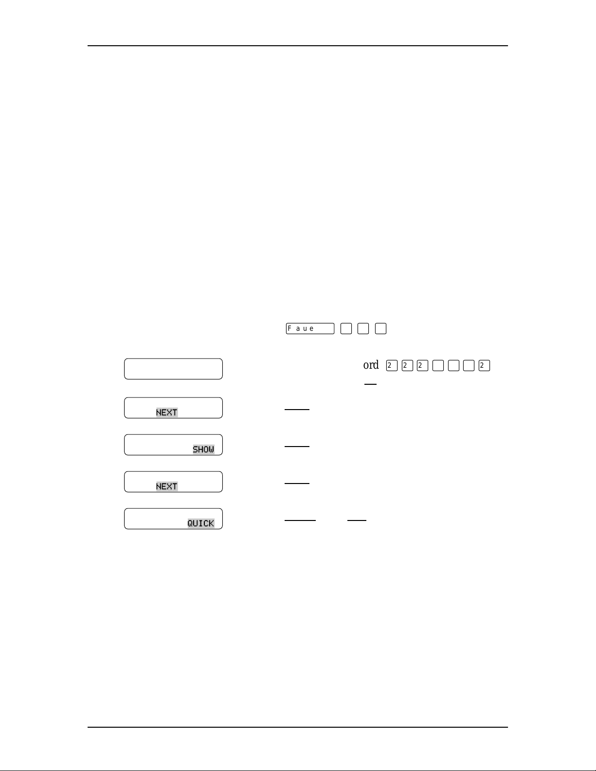
To shutdown the Norstar Voice Mail system:
ƒ · ⁄ fi .
OK
NEXT
SHOW
NEXT
until the display shows:
QUICK
, then
YES
to continue with the
¤¤¤‹‡‡¤
Password
ACCESS Server
BACK ADMIN
System shutdown
BACK NEXT
Shutdown type
QUIT GRACE
Shutdown type
QUIT NEXT
1. Press
2. Enter the default password
(ACCESS2) and press
3. Press
4. Press
5. Press
6. Press
shutdown.
The Norstar Voice Mail system shuts down in 15 seconds. For more information
about shutdown procedures, refer to the Norstar Applications Module Installation
and Maintenance Manual .
FAX Installation Guide P0886634 Issue 1.0
Page 13

Opening the NAM
1. Warn customers that Norstar Voice Mail will be out of service while you are
installing the FAX option.
2. Shutdown the Norstar Voice Mail system.
Installing the DFC on systems equipped with DVCs 7
Note: For information about performing a shutdown, refer to "
Shutting down
the Norstar Voice Mail system" on page 6.
3. Unplug the NAM power cord from the AC outlet.
4. Ground yourself by attaching one end of the grounding strap to your wrist and
the other end to a grounded metal surface.
5. Open the module door. The door may be locked. To unlock the door, use a
screwdriver to turn the lock in the bottom-right corner of the door. Turn the
lock 90° counterclockwise until the screwdriver slot is vertical.
Figure 3 Unlocking the module door
6. Remove the two screws holding the front cover to the module. The screws are
located along the top of the front cover.
7. Slide the front cover up and out from the module.
P0886634 Issue 1.0 FAX Installation Guide
Page 14

Installing the DFC on systems equipped with DVCs
Figure 4 Removing the front cover
8
Installing the DFC in the NAM
1. Make sure you are wearing your antistatic grounding strap. Ground yourself
by attaching one end of the grounding strap to your wrist and the other end to
a grounded metal surface.
2. If you are installing FAX on an earlier NAM, locate slot 7 on the expansion
bus. Remove the slot cover screw and the metal slot cover from the slot. Refer
to Figure 5
If you are installing FAX on a NAM II, locate slot 8 on the expansion bus.
Remove the slot cover screw and the metal slot cover from the slot. Refer to
Figure 6
Keep the metal slot cover and screw. You must re-install the metal slot cover
if you remove the DFC.
on page 9.
on page 9.
FAX Installation Guide P0886634 Issue 1.0
Page 15

Installing the DFC on systems equipped with DVCs 9
Figure 5 Locating the expansion bus slots on a NAM
Figure 6 Locating the expansion bus slots on a NAM II
DFC - Slot 7
DFC - Slot 8
P0886634 Issue 1.0 FAX Installation Guide
Page 16

Installing the DFC on systems equipped with DVCs
3. Switch SW1 should be set according to the following table:
Position 87654321
State off on off off on on on on
4. Switch SW2 should be set according to the following table:
Position 2 1
State on on
5. Ensure there is a jumper on position 10 of the INTERRUPT.
Note: The settings in these table are the default values and should be set
properly when the board is received. Refer to Figure 2
the location of the switch SW1, SW2 and the INTERRUPT jumpers.
on page 5 for
10
6. Carefully hold the DFC along the top only. Insert the card by aligning
between the metal groove on one side and the slot opening on the other side.
7. Push the DFC straight in until it is snugly in place. Ensure the edge connector
is firmly inserted into the socket.
8. Fasten the slot cover screw in the DFC slot cover.
Note: If there is a DVC in slot 6 of the NAM, you must connect the PEB
cable to the DFC before installation. If there is a DVC in slot 7 of the
NAM II, you must connect the PEB cable to the DFC before
installation.
FAX Installation Guide P0886634 Issue 1.0
Page 17

Installing the PEB Cable
Figure 7 shows an example of how the PEB cable is installed on an earlier NAM.
In this example, the Norstar Voice Mail module is equipped with four DVCs. The
DFC is at the right end of the PEB “chain” in slot 7 and the leftmost DVC, DVC 1,
is at the other end of the chain in slot 3.
Figure 7 NAM PEB Cable installation example
Installing the DFC on systems equipped with DVCs 11
DFC
Slot 7
DVC1
Slot 3
DVC3
Slot 4
DVC2
Slot 5
DVC4
Slot 6
Figure 8 shows an example of how the PEB cable is installed on a NAM II. In the
example, the module is equipped with four DVCs. The DFC is at the right end of
the PEB “chain” in slot 8 and the leftmost DVC, DVC 1, is at the other end of the
chain in slot 2.
Figure 8 NAM II PEB Cable installation example
DFC
Slot 8
DVC 1
Slot 2
SBC
Slot 4
DVC 2
Slot 5
DVC 3
Slot 6
DVC 4
Slot 7
To install the PEB cable:
P0886634 Issue 1.0 FAX Installation Guide
Page 18

12 Installing the DFC on systems equipped with DVCs
1. Remove all DVCs from the NAM.
2. Remove the PEB terminator XRN2 from DVC 1. Refer to Figure 9 for the
location of the PEB terminators.
Figure 9 Digital Voice Card
PEB connector
PEB terminator
XRN1
PEB terminator
XRN2
To remove a PEB terminator, place a flat-head screwdriver between the terminator
and its socket and gently pry the terminator loose.
Figure 10 Removing a PEB terminator
3. Remove both PEB terminators, XRN1 and XRN2, from any remaining DVCs.
Note: Keep the PEB terminators in a safe place. If the DFC is removed, the
terminator plugs must be re-installed on the DVCs.
4. Connect one end of the PEB cable to the PEB socket on the DFC. The PEB
cable is keyed and can only be installed one way. You must also ensure the
Pin 1 indicator (colored stripe) is on the edge furthest away from the top of the
NAM.
FAX Installation Guide P0886634 Issue 1.0
Page 19

Figure 11 Installing the PEB Cable
PEB Connector
Installing the DFC on systems equipped with DVCs 13
DFC
PEB Terminator
Interrupt SW2 SW1
5. Insert the DVCs and connect the PEB cable to each card.
Note: To ease installation, start with the DVC that is closest to the DFC and
finish with the DVC farthest away. Also make sure you connect the
PEB cable before you insert the next DVC.
6. Fold the PEB cable so it lies flat against the card edges.
7. Proceed to step 1 of Enabling the FAX software.
Enabling the FAX software
The FAX option must be enabled after installing the DFC.
After FAX capability has been added to Norstar Voice Mail, you can add or
customize Fax Overflow and Fax-on-demand information. For more information
about customizing the FAX software, refer to the Norstar Voice Mail FAX Set Up
and Operation Guide.
1. Insert the FXENABLE diskette into the floppy disk drive.
2. Plug in the module and wait for the NAM to boot from the disk. This takes
approximately three minutes.
3. After all disk activity has ceased and the light on the floppy disk drive has
gone out, unplug the NAM and remove the FXENABLE diskette from the
floppy disk drive. The FAX software is now enabled.
4. Replace the front cover. Insert the tongues on the bottom of the front cover
into the module slots.
5. Fasten the two screws holding the front cover to the module.
P0886634 Issue 1.0 FAX Installation Guide
Page 20

14 Installing the DFC on systems equipped with DVCs
6. Close the module door.
Note: To lock the door, turn the lock 90° clockwise until the screwdriver slot
is horizontal.
7. Plug the power cord into the AC outlet.
Adding a Digital Voice Card after FAX is installed
After you have installed the FAX option on the NAM, the installation of another
DVC requires a few extra steps. These extra steps are required to remove PEB
terminators and install the PEB cable.
To install a DVC:
1. Warn customers that Norstar Voice Mail will be out of service while you are
installing the expansion card.
2. Shutdown the NAM. For more information, refer to "Shutting down the
Norstar Voice Mail system" on page 6.
3. Remove the NAM power cord from the AC outlet.
4. Ground yourself by attaching one end of the grounding strap to your wrist and
the other end to a grounded metal surface.
5. Open the NAM door and remove the front cover. Refer to "
Opening the
NAM" on page 7.
6. Set the switches and jumpers on the DVC you are adding. Settings for the
switches and jumpers are listed in the Norstar Applications Module II
Installation and Maintenance Manual.
7. Remove the XRN1 and XRN2 terminators from the DVC you are installing.
Note: Keep the PEB terminators in a safe place. If the DFC is removed, the
terminator plugs must be re-installed on the DVCs.
8. Disconnect the PEB cable from the DVCs already installed in the NAM.
9. Remove the slot cover screw and the metal slot cover from the slot you are
adding the new DVC to. DVC slot assignment is listed in the
Norstar Applications Module II Installation and Maintenance Manual.
10. Insert the new DVC into the appropriate slot.
11. Connect the PEB cable to each DVC in the NAM.
FAX Installation Guide P0886634 Issue 1.0
Page 21

Installing the DFC on systems equipped with DVCs 15
12. Fold the PEB cable so it lies flat against the card edges.
13. Replace the front cover and close the module door.
14. Plug the power cord into the AC outlet.
For a detailed description about installing a DVC, refer to the
Norstar Applications Module II Installation and Maintenance Manual.
P0886634 Issue 1.0 FAX Installation Guide
Page 22

16 Installing the DFC on systems equipped with DVCs
FAX Installation Guide P0886634 Issue 1.0
Page 23

Installing the DFC on systems equipped with a BIC
Only one DFC can be installed in the NAM. The DFC connects to the Media
Services Bus Expansion Card (BEC) daughterboard attached to the Media Services
Base Interface Card (BIC) through the PCM Expansion Bus (PEB) cable. This cable
must be connected from the DFC to the BIC. The PEB cable connects the DFC to
the BIC to share the ports connected to the Norstar KSU.
The following section provides step-by-step instructions for the installation of the
FAX software, a DFC, a BEC and the PEB cable in a Norstar Voice Mail system
that is equipped with a BIC. For information on installing a DFC in a
Norstar Voice Mail system equipped with a Digital Voice Card (DVC), refer to
Installing the DFC on systems equipped with DVCs" on page 5.
"
Figure 12 Digital Fax Card
PEB Connector
Interrupt SW2 SW1
3
PEB Terminator
P0886634 Issue 1.0 FAX Installation Guide
Page 24

18 Installing the DFC on systems equipped with a BIC
Installation overview
To add Norstar Voice Mail FAX to a system equipped with a BIC you must:
• Remove the BIC from the NAM
• Install the Media Services Bus Expansion Card (BEC) Type A on to the BIC
• Re-install the BIC in the NAM
• Set the BEC jumpers
• Install the DFC
• Connect the DFC to the BIC with the PEB cable
• Enable the FAX software.
Removing the BIC
The BIC is removed when a Media Services Bus Expansion Card (BEC) is being
added to the BIC. The BEC is installed along with the DFC to provide the NAM
Norstar Voice Mail FAX capability.
To remove the BIC:
1. Shutdown the Norstar Voice Mail system. For more information, refer to
Shutting down the Norstar Voice Mail system" on page 6.
"
2. Remove the NAM power cord from the AC outlet.
3. Ground yourself by attaching one end of the grounding strap to your wrist and
the other end to a grounded metal surface.
4. Remove the front cover. Refer to "
5. If you have a NAM II, disconnect the Serial Port A and Serial Port B
connectors from the SBC. Disconnect the keyboard/mouse connector from the
SBC. Refer to Figure 13
If you have a new NAM, proceed to step 6. The new NAM has 6 expansion
slots.
on page 19. The NAM II has 8 expansion slots.
Opening the NAM" on page 7.
FAX Installation Guide P0886634 Issue 1.0
Page 25

Installing the DFC on systems equipped with a BIC 19
Figure 13 Disconnecting the Serial Ports A and B and the keyboard/mouse connector
Keyboard/mouse
backplane connector
Serial Port A Connector
Serial Port B Connector
Keyboard/mouse
Connector
6. Locate the BIC and disconnect the fiber cable.The BIC is located in Slot 2 of
the NAM II and in Slot 4 of the new NAM.
7. Remove the slot cover screw.
8. Use both hands to carefully hold the BIC along the top. Lift the BIC straight
up and out from the module. Sometimes the BIC is tightly seated and difficult
to remove. You may need to wiggle it out with a slight rocking motion.
Installing the Media Services Bus Expansion Card (BEC) on the BIC
A Media Services Bus Expansion Card (BEC) Type A is a daughterboard that is
installed on the BIC provides the BIC with the ability to connect to a Digital Fax
Card (DFC).
Before you begin the installation, you must have #2 Phillips screwdriver.
To install the BEC:
1. Ground yourself by attaching one end of the grounding strap to your wrist and
the other end to a grounded metal surface.
P0886634 Issue 1.0 FAX Installation Guide
Page 26

20 Installing the DFC on systems equipped with a BIC
2. Place the BIC on a flat surface, with the components facing up. Refer to
Figure 15
on page 21.
Caution
Failure to place the BIC on a flat surface may result in serious damage to the
BIC. While the BIC is out of the NAM, be careful not to slide or catch the back of
the BIC, this may cause damage to the pins on the back of the board.
3. Unpack the small plastic bag from the shipping container. Make sure you have
two screws and two jumpers.
4. Locate JP1 and JP2 on the BEC. JP1 and JP2 are located next to the PEB
connector.
5. Remove the two jumpers from the small plastic bag. Install the two jumpers in
an “open” position on the bottom pin of JP1 and JP2. For the jumper to be in
the “open” position, the outside half of each jumper must not cover a pin.
Refer to Figure 14 for the jumper positions.
Figure 14 BEC jumper position
JP1
Jumper Jumper
JP2
6. Unpack the BEC daughterboard from the shipping container and antistatic
bag. The BIC is equipped with two posts at the bottom of the board for
connection of the BEC daughterboard. Handle the BEC daughterboard by its
edges at all times. Do not touch any card components. Make sure you have the
two screws that came with the BEC daughterboard.
FAX Installation Guide P0886634 Issue 1.0
Page 27

Figure 15 BIC connection points
Installing the DFC on systems equipped with a BIC 21
Fiber connectors
Connection post screw hole posts PEC Slots (4)
Female BEC daughterboard connection points
7. Lightly press the BEC daughterboard down onto the female BEC
daughterboard connectors on the BIC. The BIC connection screw hole posts
should be flush with the BEC daughterboard screw holes. For the location of
the BIC and BEC daughterboard connection points, refer to Figure 15.
8. Before pressing the BEC daughterboard completely down, ensure the male
BEC daughterboard connectors line up with the female BEC daughterboard
connection points on the BIC.
9. Fasten the BEC daughterboard to the BIC connection screw hole posts using
the two screws provided. For the location of the BIC and BEC daughterboard
connection points, refer to Figure 15.
10. Insert the BIC back into the NAM. Refer to "
Re-installing the BIC in the
NAM" on page 22.
11. Replace the front cover.
12. Plug the power cord into the AC outlet.
P0886634 Issue 1.0 FAX Installation Guide
Page 28

22 Installing the DFC on systems equipped with a BIC
Re-installing the BIC in the NAM
Before you begin to install the BIC, ensure you use an antistatic strap to ground
yourself.
To re-install the BIC:
1. Ground yourself by attaching one end of the grounding strap to your wrist and
the other end to a grounded metal surface.
2. Locate expansion slot 2 for a NAM II and slot 4 for a new NAM.
3. Gently push the large ribbon cables leading to the SBC flat against the
backplane. This allows for easier installation of the BIC.
4. Carefully hold the BIC along the top. Insert the card by aligning it between
the metal groove on one side and the slot opening on the other side.
Figure 16 Re-installing the BIC in a NAM II
Slot 2
BIC
FAX Installation Guide P0886634 Issue 1.0
Page 29

Installing the DFC on systems equipped with a BIC 23
Figure 17 Re-installing the BIC in a new NAM
Slot 4
BIC
5. Push the BIC straight back until it fits snugly in place. Ensure the edge
connector is firmly inserted into the socket.
6. If you have a NAM II, reconnect the Serial Port A and Serial Port B
connectors to the SBC. Reconnect the keyboard/mouse connector to the SBC.
For the location of the connectors, refer to Figure 13
on page 19.
Note: Ensure the keyboard/mouse ribbon cable is still connected to the
backplane.
7. Fasten the slot cover screw in the BIC slot cover.
8. Replace the front cover.
P0886634 Issue 1.0 FAX Installation Guide
Page 30

24 Installing the DFC on systems equipped with a BIC
Installing the DFC in the NAM
1. Ground yourself by attaching one end of the grounding strap to your wrist and
the other end to a grounded metal surface.
2. If you have a NAM II, locate slot 8 on the expansion bus. If you have a new
NAM, locate slot 1 on the expansion bus. Remove the slot cover screw and
the metal slot cover from the slot. Keep the metal slot cover and screw. You
will have to re-install the metal slot cover if you remove the DFC.
3. Switch SW1 should be set according to the following table:
Position 87654321
State off on off off on on on on
4. Switch SW2 should be set according to the following table:
Position 2 1
State on on
5. Ensure there is a jumper on position 10 of the INTERRUPT.
Note: The settings in these table are the default values and should be set
properly when the board is received. Refer to Figure 12
the location of the switch SW1, SW2 and the INTERRUPT jumpers.
6. Carefully hold the DFC along the top only. Insert the card by aligning
between the metal groove on one side and the slot opening on the other side.
7. Push the DFC straight in until it is snugly in place. Ensure the edge connector
is firmly inserted into the socket.
8. Fasten the slot cover screw in the DFC slot cover.
Connecting the DFC to the BIC with the PEB Cable
There are no fiber connections to the DFC. The DFC uses the voice ports on the BIC
to connect the fax ports to fax machines or a call.
on page 17 for
Only one DFC can be installed in a NAM. The DFC connects to the BEC
daughterboard attached to the BIC through the PCM Expansion Bus (PEB) cable.
This cable must be connected from the DFC to the BIC. The PEB cable connects
the DFC to the BIC to share the ports connected to the Norstar KSU.
FAX Installation Guide P0886634 Issue 1.0
Page 31

Installing the DFC on systems equipped with a BIC 25
Note: The BIC must have a BEC daughterboard installed before it can be
connected to the DFC. For instructions on installing the BEC
daughterboard, refer to "
Installing the Media Services Bus Expansion Card
(BEC) on the BIC" on page 19.
Figure 18 shows an example of how the PEB cable is installed on a NAM II. The
DFC is at the right end of the PEB “chain” in slot 8 and the BIC is at the other end
of the chain in slot 2. The three extra connectors on the PEB cable remain empty.
Figure 19 on page 26 shows how the PEB cable is installed on a new NAM. The
DFC is in slot 1 and the BIC is at the other end of the chain in slot 4. The three extra
connectors on the PEB cable remain empty.
You must use the PEB cable provided in the BEC shipping container. The PEB
cable is pre-folded for correct installation.
WARNING
The microprocessor heat sink may be hot. Pay careful attention not to touch the
heat sink when installing the PEB cable.
Figure 18 Connecting the BIC to the DFC in a NAM II
PEB Cable
Empty PEB
cable connectors
DFC connector
BIC connector located
on the BEC daughterboard
P0886634 Issue 1.0 FAX Installation Guide
Page 32

26 Installing the DFC on systems equipped with a BIC
Figure 19 Connecting the BIC to the DFC
DFC connector
PEB Cable
DFC in slot 1
BIC in slot 4
BIC connector located
on the BEC daughterboard
To connect the BIC to the DFC with the PEB cable:
WARNING
The microprocessor heat sink may be hot. Pay careful attention not to touch the
heat sink when installing the PEB cable.
1. Connect one end of the PEB cable to the PEB socket on the DFC. The PEB
cable is keyed and can only be installed one way. You must also ensure the
Pin 1 indicator (colored stripe) is on the edge furthest away from the top of the
module.
2. Connect the last connector on the PEB cable to the BIC. The remaining
connectors on the PEB cable can remain empty and can be folded and gently
pushed flat against the backplane.
3. Proceed to step 1 of Enabling the FAX software.
FAX Installation Guide P0886634 Issue 1.0
Page 33

Enabling the FAX software
The FAX option must be enabled after installing the DFC.
After FAX capability has been added to Norstar Voice Mail, you can add or
customize Fax Overflow and Fax-on-demand information. For more information
about customizing the FAX software, refer to the Norstar Voice Mail FAX Set Up
and Operation Guide.
1. Insert the FXENABLE diskette into the floppy disk drive.
2. Plug the power cord into the AC outlet and wait for the NAM to boot from the
disk. This takes two to three minutes.
3. When all disk activity has ceased and the light on the floppy disk drive goes
out, unplug the NAM and remove the FXENABLE diskette from the floppy
disk drive.
4. Replace the front cover. Insert the tongues on the bottom of the front cover
into the module slots.
Installing the DFC on systems equipped with a BIC 27
5. Fasten the two screws holding the front cover to the module.
6. Close the module door. To lock the door, turn the lock 90° clockwise until the
screwdriver slot is horizontal.
7. Plug the power cord into the AC outlet.
P0886634 Issue 1.0 FAX Installation Guide
Page 34

28 Installing the DFC on systems equipped with a BIC
FAX Installation Guide P0886634 Issue 1.0
Page 35

Tell us what you think...
This is your document. Nortel wants it to work well for you.
Please take a few minutes to answer the questions on the other side of this page. Fax it
back to us at the number provided, or mail it to the address below.
Your comments will be used to make improvements.
Thank you. We appreciate your time and consideration.
Nortel Product Training and Documentation
Return mail address:
29
Documentation User Comments Survey
Nortel Product Training and Documentation
P.O. Box 833858
M/S H300
Richardson, TX 75083-3858
USA
FAX Installation Guide P0886634 Issue 1.0
Page 36

30
Fax to:
Documentation User Comments Survey
Nortel Product Training and Documentation
1-972-684-8699
Please circle the most appropriate number on the scale for each question.
1. Overall, are you satisfied with this document?
Yes7654321No
2. Is it easy to find information in this document?
Yes7654321No
3. Have you found the information in this document to be technically accurate?
Yes7654321No
4. Is this document clearly written?
Yes7654321No
5. Is the information in this document complete for its purpose?
Yes7654321No
6. Does this document help you do your job?
Yes7654321No
Comments:
Optional:
Your name___________________________________
Fax___________________________________
Company___________________________________
FAX Installation Guide P0886634 Issue 1.0
Page 37

1-800-4 NORTEL
www.nortel.com/norstar
Norstar is a trademark of Northern Telecom.
P0886634 Issue 1.0
Printed in Canada
 Loading...