

Page 1

555-7101-217
555-7101-217
CallPilot
Installation and Configuration
Part 2: 1001rp Server Hardware Installation
Product release 2.02 Standard 1.0 May 2003
Page 2

P0605618
Page 3

CallPilot
Installation and Configuration
Part 2: 1001rp Server Hardware Installation
Publication number: 555-7101-217
Product release: 2.02
Document release: Standard 1.0
Date: May 2003
Copyright © 2003 Nortel Networks, All Rights Reserved
Printed in Canada
Information is subject to change without notice. Nortel Networks reserves the right to make
changes in design or components as progress in engineering and manufacturing may
warrant.
The process of transmitting data and call messaging between the CallPilot server and the
Meridian 1 switch or Succession CSE 1000 system is proprietary to Nortel Networks. Any
other use of the data and the transmission process is a violation of the user license unless
specifically authorized in writing by Nortel Networks prior to such use. Violations of the
license by alternative usage of any portion of this process or the related hardware
constitutes grounds for an immediate termination of the license and Nortel Networks
reserves the right to seek all allowable remedies for such breach.
This page and the f ollowing p age are co nsider ed the titl e page, an d contain Nortel Ne tworks
and third-party trademarks.
Page 4

*Nortel Networks, the Nortel Networks logo, the Globemark, and Unified Networks, BNR,
CallPilot, DMS, DMS-100, DMS-250, DMS-MTX, DMS-SCP, DPN, Dualmode, Helmsman,
IVR, MAP, Meridian, Meridian 1, Meridian Link, Meridian Mail, Norstar, SL-1, SL-100,
Succession, Supernod e, Symposium , Telesis, and Unity are trademarks o f Nortel Net works.
3COM is a trademark of 3Com Corporation.
ACCENT is a trademark of Accent Software International Ltd.
AMDEK is a trademark of Amdek Corporation.
AT&T is a trademark of American Telephone and Telegraph Corporation.
ATLAS is a trademark of Quantum Corporation.
ATRIA is a trademark of Pure Atria Corporation.
BLACKBERRY is a trademark of Research in Motion Limited.
CASEWARE is a trademark of Caseware International, Inc.
CONTINUUS is a trademark of Continuus Software Corporation.
CRYSTAL REPORTS is a trademark of Seagate Software Inc.
DEFINITY is a trademark of Avaya Inc.
DIALOGIC is a trademark of Dialogic Corporation.
EUDORA is a trademark of Qualcomm.
EXCHANGE.NET , INTERNET EXPLORER, LINKEXCHANGE, MICROSOF T, MICROSOFT
EXCHANGE SERVER, MS-DOS, OUTLOOK, POWERPOINT, WINDOWS, WINDOWS
MEDIA, and WINDOWS NT are trademarks of Microsoft Corporation.
GROUPWISE and NOVELL are trademarks of Novell Inc.
HITACHI is a trademark of Hitachi Limited.
INTEL is a trademark of Intel Corporation.
LOGITECH is a trademark of Logitech, Inc.
NETSCAPE COMMUNICATOR is a trademark of Netscape Communications Corporation.
PCANYWHERE is a trademark of Symantec Corporation.
PROMARK and RHOBOT are trademarks of DMI Promark, Inc.
RADISYS is a trademark of Radisys Corporation.
SLR4, SLR5, and TANDBERG are trademarks of Tandberg Data ASA.
SYBASE is a trademark of Sybase, Inc.
UNIX is a trademark of X/Open Company Limited.
US ROBOTICS, the US ROBOTICS logo, and SPORTSTER are trademarks of US
Robotics.
VOICEBRIDGE is a trademark of Voice Technologies Group Inc.
Page 5

Publication history
May 2003
October 2002
Release 2.02, Standard 1.0 of CallPilot Installation
and Configuration, Part 2: 1001rp Server
Hardware Installation is issued for general release.
Information on single-point grounding has been
added to Chapter 4, “Installing the server and
connecting the peripheral devices”.
Standard 1.0 of CallPilot Installation and
Configuration, Part 2: 1001rp Server Hardware
Installation is issued for general release.
Part 2: 1001rp Server Hardware Installation v
Page 6

Publication history Standard 1.0
vi CallPilot
Page 7

Contents
1 1001rp server description 9
Server features . . . . . . . . . . . . . . . . . . . . . . . . . . . . . . . . . . . . . . . . . . . . . . 10
Slot assignments . . . . . . . . . . . . . . . . . . . . . . . . . . . . . . . . . . . . . . . . . . . . . 14
IRQ mapping table . . . . . . . . . . . . . . . . . . . . . . . . . . . . . . . . . . . . . . . . . . . 17
Network connectivity . . . . . . . . . . . . . . . . . . . . . . . . . . . . . . . . . . . . . . . . . 19
Supported peripheral devices . . . . . . . . . . . . . . . . . . . . . . . . . . . . . . . . . . . 24
2 Preparing for installation 25
Installation overview. . . . . . . . . . . . . . . . . . . . . . . . . . . . . . . . . . . . . . . . . . 26
Unpacking the 1001rp server . . . . . . . . . . . . . . . . . . . . . . . . . . . . . . . . . . . 29
Removing the front bezel and server cover . . . . . . . . . . . . . . . . . . . . . . . . 31
Inspecting the server interior . . . . . . . . . . . . . . . . . . . . . . . . . . . . . . . . . . . 35
3 Power supply installation 37
Safety precautions. . . . . . . . . . . . . . . . . . . . . . . . . . . . . . . . . . . . . . . . . . . . 38
Section A: Installing the power supply modules (AC or DC) 39
Installing the second power supply module (AC or DC) . . . . . . . . . . . . . . 40
Section B: Setting up DC power source for a 1001rp DC
server 43
DC wire gauge tables . . . . . . . . . . . . . . . . . . . . . . . . . . . . . . . . . . . . . . . . . 44
DC rack cabling . . . . . . . . . . . . . . . . . . . . . . . . . . . . . . . . . . . . . . . . . . . . . 46
About the Power Distribution Unit. . . . . . . . . . . . . . . . . . . . . . . . . . . . . . . 48
Bringing power and ground into the PDU . . . . . . . . . . . . . . . . . . . . . . . . . 50
Part 2: 1001rp Server Hardware Installation vii
Page 8

Contents Standard 1.0
4 Installing the server and connecting the peripheral
devices 53
Installing the server. . . . . . . . . . . . . . . . . . . . . . . . . . . . . . . . . . . . . . . . . . . 54
Preparing the modem . . . . . . . . . . . . . . . . . . . . . . . . . . . . . . . . . . . . . . . . . 55
Connecting peripherals to the server . . . . . . . . . . . . . . . . . . . . . . . . . . . . . 59
Connecting the server to the ELAN . . . . . . . . . . . . . . . . . . . . . . . . . . . . . . 62
Connecting the server to the CLAN (optional). . . . . . . . . . . . . . . . . . . . . . 64
Installing the Nortel Networks software feature key adapter. . . . . . . . . . . 66
Connecting the server to power . . . . . . . . . . . . . . . . . . . . . . . . . . . . . . . . . 68
Index 75
viii CallPilot
Page 9

Chapter 1
1001rp server description
In this chapter
Server features 10
Slot assignments 14
IRQ mapping table 17
Network connectivity 19
Supported peripheral devices 24
Part 2: 1001rp Server Hardware Installation 9
Page 10
1001rp server description Standard 1.0
Server features
Introduction
This section provides a general overview of the 1001rp server.
Server dimensions and weight
Height 32 cm (12.5 in.)
Width 48.3 cm (19 in.)
Depth (distance from front to back)
without front bezel
with front b ezel
Weight of fully loaded system 45.5 kg (100 lbs)
49.5 cm (19.5 in.)
53.3 cm (21 in.)
10 CallPilot
Page 11
May 2003 1001rp server description
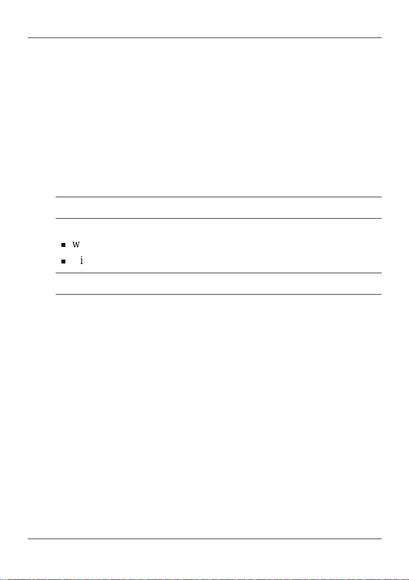
Front panel features (front view without the front bezel)
The front view of the 1001rp se rver chassis shows redundant dua l fans to the
left and the right of the status panel. The left drive bay holds six SCSI hard
drives with hot-plug gabl e car rier s. The me dia dr ive ba y, located to the right ,
houses the CD-ROM, tape drive, and floppy disk drive.
Hot-swap fan modules
Status panel
5-pin
Hot-swap
hard disk
drives
keyboard
connector
(Not used)
Reset
button
CD-ROM
drive
Tape
drive
Floppy
disk drive
G100697
Alarm board
The alarm board is located under the baseboard. It connects to the status
display panel on the front.
Part 2: 1001rp Server Hardware Installation 11
Page 12
1001rp server description Standard 1.0
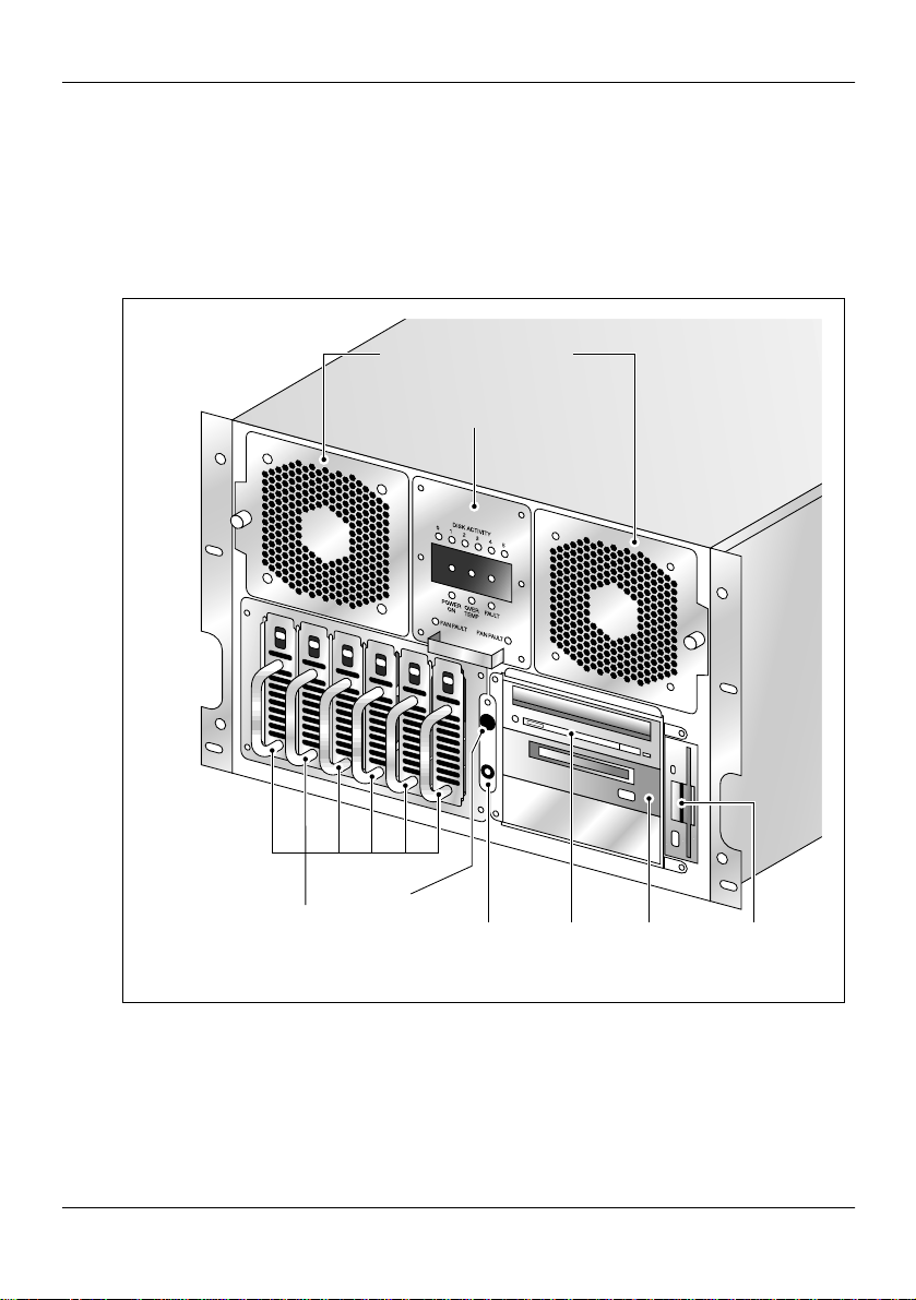
Rear panel diagram
Note: The following diagram shows the slot locations in the rear panel:
Slot 20
Video
card
CLAN
card
COM2COM1
ELAN
card
SBC
card
(slot 8)
PS/2
Keyboard
PS/2
Mouse
Parallel
port (LPT1)
Slot 1
Power
switch
Power
input
G101720
The above diagram shows the power switch and power input for an AC
server. The rest of the diagram is the same for AC or DC servers.
12 CallPilot
Page 13
May 2003 1001rp server description
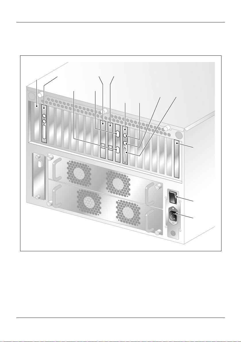
Overhead view of empty server showing PCI and ISA
connectors
The following diagram shows the location of the PCI, SBC, and ISA
connectors inside th e se rver. The view i n the dia gram is from the rear of the
server. For slot assignments, see “Slot assignments” on page 14. You must
be able to identify slot locations fo r later steps in the CallPilot installa tion.
PCI
connectors
SBC
connector
ISA
connectors
G101740
Part 2: 1001rp Server Hardware Installation 13
Page 14

1001rp server description Standard 1.0
Slot assignments
Introduction
The slot assignment tables show the following:
the physical location of boards inside the server, relative to other boards
the order in which boards are installed (for example, board #1, 2, 3, and
so on)
how the boards are represented in some CallPilot Manager applications
(such as the Maintenance Administration page)
the maximum capacity for each switch connectivity
Note: Your server may vary depending on what was ordered from Nortel
Networks. Therefore, your server may not have all of the slots populated.
Slot definition and slot numbering
In these tables, the term “slot” refers to the available slot openings in the
chassis, not the PCI or ISA connectors inside the server.
Look at the serve r fr om the r ear (see “Rear pane l diagra m” on page 12). Th e
slots are numbered from right to left, 1 to 20. Now, look at the server from
the front. The slots are numbered from left to right.
1001rp slot assignments
CallPilot-
Slot
number
Slot 1 BRD01 Not used Not used
Slot 2 BRD02 Not used Not used
14 CallPilot
assigned board
a
label
Meridian 1 Succession CSE 1000
Page 15

May 2003 1001rp server description
CallPilot-
Slot
number
assigned board
a
label
Meridian 1 Succession CSE 1000
Slot 3 BRD03 Not used Not used
Slot 4 BRD04 Not used Not used
Slot 5 BRD05 Not used Not used
Slot 6 BRD06 Not used Not used
Slot 7 BRD07 Not used Not used
Slot 8 BRD08 Single Board Computer Single Board Computer
Slot 9 BRD09 Reserved for COM1 and
COM2 I/O bracket
Reserved for COM1 and
COM2 I/O bracket
Slot 10 BRD10 ELAN Network card ELAN Network card
Slot 11 BRD11 CLAN Network card CLAN Network card
b
Slot 12
Slot 13 BRD13 MPB16-4 board #2
BRD12 MPB16-4 board #1 MPB16-4 board #1
MPB16-4 board #2
(optional)
(optional)
Slot 14 BRD14 Not used Not used
Slot 15 BRD15 Not used Not used
Slot 16 BRD16 Not used Not used
Slot 17 BRD17 Not used Not used
Slot 18 BRD18 Not used Not used
Slot 19 BRD19 VGA card (monitor
connection)
VGA card (monitor
connection)
Part 2: 1001rp Server Hardware Installation 15
Page 16

1001rp server description Standard 1.0
CallPilot-
Slot
number
assigned board
a
label
Meridian 1 Succession CSE 1000
Slot 20 BRD20 PCI RAID controller PCI RAID controller
a. On some CallPilot Manager applications, the CallPilot-assigned board label
appears. This label corresponds to the slot number. For example, BRD12 refers to
the board in slot 12.
b. For Meridian 1 and Succession CSE 1000, the first MPB16-4 board must be
installed in slot 12.
16 CallPilot
Page 17

May 2003 1001rp server description
IRQ mapping table
Introduction
The following table displays the assignments for each Interrupt Request
Line (IRQ) with the associated slot or device. You do not need this
information for installation, but you may need it for troubleshooting.
Note: IRQs 9, 10, 11, and 15 are assigned to system PCI slots rather than to
specific d evices.
IRQ Slot or device
0Timer
1 Keyboard
2System / Unused
3 Serial port 2 (COM2)
4 Serial port 1 (COM1)
5Available
6 Floppy controller
7 Parallel port (LPT1)
8Real Time Clock
9 Assigned to slots 9, 15, and 20
10 Assigned to slots 10, 13, and 19
11 Assigned to slots 11, 14, and 17
12 PS/2 mouse
Part 2: 1001rp Server Hardware Installation 17
Page 18

1001rp server description Standard 1.0
IRQ Slot or device
13 Math coprocessor
14 Primary EIDE controller
15 Assigned to slots 12, 16, and 18
18 CallPilot
Page 19

May 2003 1001rp server description
Network connectivity
Introduction
This section describes how the 1001rp server can be integrated into your
network. The integration depends on the type of switch you are using.
ATTENTION
Note: The diagrams show a tower server. However, the same configuration
applies to the 1001rp server.
To secure the CallPilot server from unauthorized access,
ensure that the CallPilo t network is inside your
organization’s firewall.
Part 2: 1001rp Server Hardware Installation 19
Page 20
1001rp server description Standard 1.0
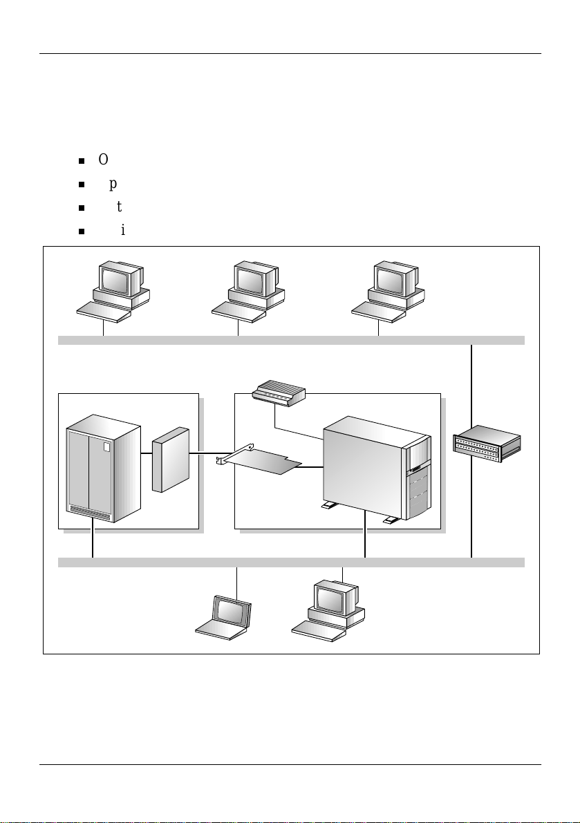
Sample network setup: Meridian 1
The following diagram shows a CallPilot server sample network setup with
a Meridian 1 switch. The Meridian 1 switch can be one of the following:
Option 11C or Option 11C Mini
Option 51C
Option 61C
Options 81 and 81C
Meridian 1 switch
Desktop
client PC
MGate
card
Desktop
client PC
Customer LAN (optional)
Modem
MPB16-4
board
Embedded LAN
Laptop
Web-enabled
administrative
PC
CallPilot server
Router or
Ethernet
switch
(optional)
Web-enabled
administrative
PC
G101626
20 CallPilot
Page 21
May 2003 1001rp server description
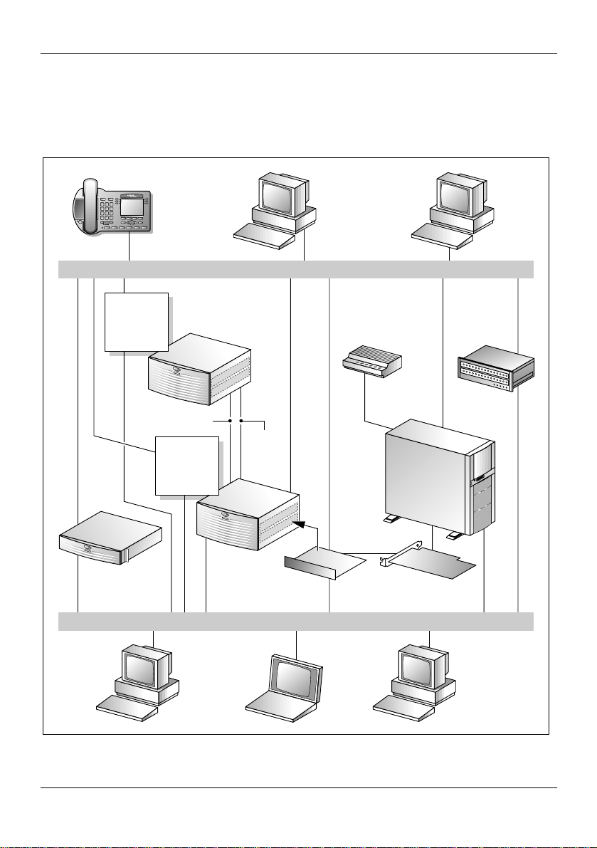
Sample network setup: Succession CSE 1000
The following diagram shows a CallPilot server network setup with a
Succession CSE 1000 system:
Telephony LAN/Customer LAN (10/100BaseT or 100BaseT)
Internet
Telephony
Gateway
Line Card
Succession
CSE 1000
Call Server
i2004
Internet
phonesets
Succession
CSE 1000 Media
Gateway Expansion
CE-MUX
Internet
Telephony
Gateway
Line Card
Succession
CSE 1000
Media
Gateway
Embedded LAN (10BaseT)
DS-30x
Web-enabled
CallPilot
administrative
PC
MGate
card
Modem
Desktop
client
PC
Router or
Ethernet
switch
(optional)
CallPilot
server
MPB16-4
board
Optivity
Telephony
Manager
PC
Laptop
Web-enabled
CallPilot
administrative
PC
G101636
Part 2: 1001rp Server Hardware Installation 21
Page 22

1001rp server description Standard 1.0
In this illustration, the telephony LAN (TLAN) provides IP connectivity
between the Succession CSE 1000 system and the i2004 Internet phonese ts.
The connection between the Call Server and Media Gateway can be pointto-point, or it can be through the LAN, if the system is installed in a
distributed data network.
For information about the Succession CSE 1000 system and i2004 Internet
phoneset bandwidth and network requirements, refer to the Succession
Communication Server for Enterpri se 1000 Planning and Installati on Guide
(NTP 553-3023-210).
Switch connectivity
For more details about how the 1001rp server and switch connection is
establish ed, refer to P art 3 of the CallPilot Installation and Configuration
binder.
CallPilot ELAN and CLAN network setup
The 1001rp server pro vides 10- o r 100Bas e-T Ethern et connect ivity t hrough
network interface cards (NIC) installed in the server. See “Slot assignments”
on page 14 for details on the l ocation of ne twork cards . The funct ion of each
network card is described below:
One network card provides connectivity to the ELAN.
For information about the ELAN’s purpose and requirements, see
“About the ELAN” in Part 1 of the CallPilot In stallation and
Configuration binder.
A second network card is optional.
This optional NIC is required only for Meridian 1 or Succession
CSE 1000 systems that require a CLAN connection (in addition to the
ELAN connection). The CLAN provides data connectivity between
desktop and web messaging clients, web-enabled administrative PCs,
and the CallPilot server.
22 CallPilot
Page 23

May 2003 1001rp server description
Network requirements
Appropriate networking equipment must be available for both the CLAN
and ELAN.
The CLAN and ELAN must be properly configured for correct CallPilot
operation. To ensure correct configuration, Nortel Networks recommends
that you consult a network specialist.
ATTENTION
For important con side ratio ns abou t usin g the EL AN in
your network, see “About the ELAN” in Part 1 of the
CallPilot Installation and Configuration binder.
Remote access connectivity
The RS-232 COM 1 connector on the rear of the 100 1rp ser ve r pr ovides the
connection to an external modem. The modem allows administrators and
technical support personnel to administer the 1001rp server from a remote
location.
pcAnywhere is used to establish the remote access connection to the server.
Part 2: 1001rp Server Hardware Installation 23
Page 24

1001rp server description Standard 1.0
Supported peripheral devices
Introduction
This section identifies external devices that are supported by the 1001rp
server. The following table describes the supported peripheral devices:
Device Description
Modem A 56 Kbps external modem (NTRH9078) provides
remote access to the 1001rp server. The modem connects
to the RS-232 COM1 connector on the rear of the ser ver.
Since the modem is an externa l device, it requires i ts own
AC power source.The 33.6 Kbps modem (NTRH9016) is
also supported, but has been replaced by the 56 Kbps
modem for new systems.
Ethernet hub A 10BaseT Ethernet hub provides the ELAN connection
between the 1001rp server and the Meridian 1 switch or
Succession CSE 1000 system. The customer can supply
a hub from third-party vendors or purchase the 3Com
10BaseT Ethernet hub (NTRH9017) from Nortel
Networks.
Since the hub is an external device, it requires an AC
power source.
Monitor, keyboard,
and mouse
14" monitor: NTRH901 1
Since the monitor is an external device, it requires its
own AC power source.
Keyboard: NTRH9013
Mouse: NTRH9014
24 CallPilot
Page 25

Chapter 2
Preparing for installation
In this chapter
Installation overview 26
Unpacking the 1001rp server 29
Removing the front bezel and server cover 31
Inspecting the server interior 35
Part 2: 1001rp Server Hardware Installation 25
Page 26

Preparing for installation Standard 1.0
Installation overview
Introduction
This section provides an overvi ew of the step s requir ed to inst all the 1001rp
server and peripheral devices.
Installation checklist
The following checklist iden ti fi es the tasks that must be performed when
installing the CallPilot server. For detailed instructions, see Chapter 4,
“Installing the server and connecting the peripheral devices.”
When you are finished, c ontinue with Part 3 of the CallPi lot Installat ion and
Configuration binder.
Step Description Check
1 Ensure that you have reviewed the “Installing CallPilot” section
❒
in Part 1 of the CallPilot I nstallatio n and Configura tion binder,
and completed stage 1 of the “Installation checklist.”
2 Unpack the server, and ensure you have all the items you need
❒
(see page 29).
Complete the following checklists that are provided in Part 1 of
the CallPilot Installation and Configuration binder:
“CallPilot software media and documentation checklist”
“CallPilot server hardware checklist”
3 Remove the front bezel and server cover, and inspect the
❒
interior (see pages 31 and 35).
4 Replace the server cover. ❒
5 Install th e power supply modules in the server (see page 4 0). ❒
26 CallPilot
Page 27

May 2003 Preparing for installation
Step Description Check
6 For a DC-powered server, set up the DC power source (see
❒
page 43).
7 Place the 1001rp server in the chosen location (see page 54). ❒
8 Replace the front bezel (see page 34). ❒
9 Set the DIP switches on the modem (see page 57). ❒
10 Connect the 1001rp server and devices as follows:
Connect the monitor, keyboard, and mouse (see page 59). ❒
Connect the modem (see page 60). ❒
Connect the 1001rp server to the ELAN hub (Meridian 1 or
❒
Succession CSE 1000 only) (see page 62).
Connect the 1001rp server to the CLAN hub (optional) (see
❒
page 64).
Install the software feature key ada pter (see page 66). ❒
Connect the power cords for all devices, and then power
❒
them up.
11 Start the 1001rp server (see page 68). ❒
Part 2: 1001rp Server Hardware Installation 27
Page 28

Preparing for installation Standard 1.0
Conventions for warnings
You may encounter the following types of warnings in this guide. Do not
ignore them.
DANGER
.
.
.
ATTENTION
Risk of electric shock
Warns you of an immediate electrical hazard which, if not
avoided, will result in shock, serious injury, or death.
WARNING
Risk of personal injury
Warns you of a situation in which you can be injured if
instructions are not followed exactly as stated.
CAUTION
Risk of equipment damage
Alerts you to situati ons where data can be lost or damaged,
equipment can be damaged, actions can result in service
interruption, and productive time can be lost.
Provides infor mation that is essenti al to th e comp letio n
of a task.
28 CallPilot
Page 29

May 2003 Preparing for installation
Unpacking the 1001rp server
Introduction
Follow this procedure to unpack the server and peripherals.
WARNING
.
Risk of personal injury
The 1001rp CallPilot server weighs approximately 34 kg
(75 lbs) as shipped from manufacturing. To prevent personal
injury, have someone help you to unpack and position the
server.
To unpack the equipment
ATTENTION
1 Carefully open the cardboard carton containing the server.
2 Remove the server from the carton and set it on the floor.
3 Carefully open the cartons containing the monitor, keyboard, mouse,
modem, and ELAN hub (if supplied), and set the peripherals aside.
As you unpack ea ch ite m, che ck it off again st the
packing list, a s well as a gain st the fo llowin g
checklists provi ded in Part 1 o f the CallP ilot
Installation a nd Con figur ation binder:
“CallPilot software media and documentation
checklist”
“CallPilot server hardware checklist”
4 Put all manuals, CD-ROMs, operating system disks, any disks for
peripherals, and the Windows NT emergency repair disk in a safe place.
Part 2: 1001rp Server Hardware Installation 29
Page 30

Preparing for installation Standard 1.0
5 Save all packing materials and cartons in case you must return any
equipment to the carrier.
What’s next?
Remove the server cover so that you can inspect the interior of the server.
See “Removing the front bezel and server cover” on page 31.
30 CallPilot
Page 31

May 2003 Preparing for installation
Removing the front bezel and server cover
Introduction
To access the server interior, you must remove both the front bezel and the
server cover.
To remove the front bezel, see page 32.
To remove the server cover, see page 33.
To replace the front bezel, see page 34.
About the front bezel doors
Two locked doors on the front of the server cover the front panel, including
the CD-ROM drive and tape drive.
These doors are part of the front bezel, which covers the front of the server.
You must unlock the front bezel doors before you can remove the front
bezel.
Part 2: 1001rp Server Hardware Installation 31
Page 32

Preparing for installation Standard 1.0
To remove the front bezel
CAUTION
.
Do not attem pt to move o r lift the server before rem oving the
front bezel; the server can disengage from the bezel and fall.
1 Unlock and open the double doors of the front bezel. See “A” in the
diagram below.
2 Firmly grasp the front bezel by the hand-holds on either side of the
chassis, and pull the front bezel from the chassis.
A
Risk of equipment damage
B
G101733
32 CallPilot
Page 33

May 2003 Preparing for installation
To remove the server cover
DANGER
.
High current inside the chassis can cause severe injury.
CAUTION
Risk of equipment damage
Risk of electric shock
.
Take precautions to protect internal components. Electrostatic
discharge (ESD) can r ender boar ds damaged or u nusable. Wear
an ESD wrist strap.
1 Remove the front bezel (see page 32).
2 Loosen the three thumbscrews at the rear of the top cover.
3 Remove the server cover by pulling the cover toward the rear of the
chassis, and then lifting it up and off.
4 Clip the lead from your ESD wrist strap to an unpainted metal section of
the chassis.
What’s next?
Continue with “Inspecting the server interior” on page 35.
Part 2: 1001rp Server Hardware Installation 33
Page 34

Preparing for installation Standard 1.0
To replace the front bezel after installation is complete
When the CallPilot server installation is complete and the server is in its
final location, replace the front bezel.
1 Align the front bezel with the ball studs located at each faceplate corner.
See the diagram below:
Clips inside
front bezel
G101734
2 Apply pressure evenly until the bezel snaps onto each ball stud.
3 Close and lock the double doors of the front bezel.
34 CallPilot
Page 35

May 2003 Preparing for installation
Inspecting the server interior
Introduction
You should perform a visual inspection for loose components, foreign
matter, or shipping damage inside the server.
CAUTION
.
Risk of equipment damage
When work ing with interior components, use an ESD wrist
strap to protect static-sensitive components.
To inspect the server interior
1 Carefully check all the cards to ensure they are fully seated on the
baseboard.
2 Check for any loose wires or foreign objects, such as loose screws,
inside the chassis.
3 Review the slot locations (see “Slot definition and slot numbering” on
page 14).
4 Do one of the following:
IF THEN
you observe any damage contact your Nortel Networks
technical support representative.
components have become
loose
secure them.
Refer to the procedures in Part 5 of
the CallPilot Installation and
Configuration binder.
Part 2: 1001rp Server Hardware Installation 35
Page 36

Preparing for installation Standard 1.0
IF THEN
you are satisfied that the
1001rp server has arrived
at your site undamaged
replace the server cover and
proceed with the hardware
installation.
See “Installation checklist” on page
26.
Note: Do not reinstall the front
bezel until the server is in its final
location and the CallPilot
installation is compl ete .
36 CallPilot
Page 37

Chapter 3
Power supply installation
In this chapter
Safety precautions 38
Section A: Installing the power supply modules (AC or DC) 39
Installing the second power supply module (AC or DC) 40
Section B: Setting up DC power source for a 1001rp DC server 43
DC wire gauge tables 44
DC rack cabling 46
About the Power Distribution Unit 48
Bringing power and ground into the PDU 50
Part 2: 1001rp Server Hardware Installation 37
Page 38

Power supply installation Standard 1.0
Safety precautions
Equipment handling guidelines
External power equipment, such as an uninterruptible power supply (UPS),
is usually very heavy. This equipment requires special handling procedures
and additional personnel for unloading and installation. Be aware of weight
distribution, and prevent the equipment room floor from being overly
stressed.
Safety information
In DC systems, locate the service panel near the entry to the room
containing the DC power system that supplies the server.
DANGER
.
Risk of electric shock
Procedures involving electrical connections must only be
performed by qualified personnel.
Ensure that you obey all displayed warning notices on power
equipment and connections.
38 CallPilot
Page 39

May 2003 Power supply installation
Section A: Installing the power
supply modules (AC
or DC)
In this section
Installing the second power supply module (AC or DC) 40
Part 2: 1001rp Server Hardware Installation 39
Page 40

Power supply installation Standard 1.0
Installing the second power supply module (AC or DC)
Introduction
One power supply module is shipped installed. The second power supply
module is shipped uninstalled and must be installed as part of the CallPilot
installation.
AC versus DC systems
The power supply modules are similar in appearance for both AC and DC
1001rp servers. The procedures in this section apply to both AC and DC
1001rp servers.
About the power supply module
After the server is powered up (later i n this gui de), the p ower sup ply module
LED indicates its status.
A green LED indicates that th e power suppl y module is worki ng properly. If
the LED on the power supply mo dule is unlit or red, t he module i s fail ing or
has failed. Other indicators are an alarm sounding and the power supply
LED on the status display on the front of the server turning red.
40 CallPilot
Page 41

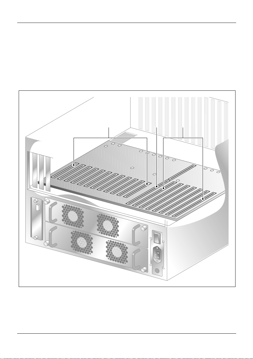
May 2003 Power supply installation
The diagram below shows the location of the power supply modules in a
server that has both power supply modules installed:
Power supply modules
G101751
Part 2: 1001rp Server Hardware Installation 41
Page 42

Power supply installation Standard 1.0
To install the power supply module
DANGER
.
Risk of electric shock
High current inside the chassis can cause severe injury.
The server is shipped with one power supply modul e instal led in the bottom
power supply bay. You must install the second power supply module, as
described here:
1 Align the power supply module with the top power supply bay.
2 Slide the power supply module into the bay until the module is secured
by its connector.
Use some force, if necessary.
3 Secure the power supply module to the chassis with two thumbscrews at
the corners of the power supply faceplate.
What’s next?
Do one of the following:
IF THEN
this is an AC-powered server continue with Chapter 4, “Installing
the server and connecting the
peripheral devices,” on page 53.
this is a DC-powered server continue with Section B: “Setting up
DC power source for a 1001rp DC
server,” on page 43.
42 CallPilot
Page 43

May 2003 Power supply installation
Section B: Setting up DC power
source for a 1001rp DC
server
In this section
DC wire gauge tables 44
DC rack cabling 46
About the Power Distribution Unit 48
Bringing power and ground into the PDU 50
Part 2: 1001rp Server Hardware Installation 43
Page 44

Power supply installation Standard 1.0
DC wire gauge tables
Introduction
The tables in this section specify the DC power feed wire requirements.
Cabinet and module DC feed recommended wire gauge
specifications
Length #10 AWG #8 AWG #6 AWG
Junction
box #4
AWG
Junction
box #4
AWG
0–30 m (100 ft) yes yes yes yes yes
0–45 m (150 ft) no yes yes yes yes
0–75 m (250 ft)nonoyesyesyes
0–135 m (450 ft) no no no yes yes
0–210 m (700 ft) no no no no yes
Over 210 m (700 ft) no no no no no
Notes:
1. Cabinet and module ground wire specification is #10 AWG insulated
green safety ground wire.
2. Cabinet conduit can be 1.91 cm (0. 75 in.) or 3.18 cm (1.25 i n.), a nd must
be insulated from cabinet ground.
44 CallPilot
Page 45

May 2003 Power supply installation
Metric wire conversion
AWG N o.
Industry standard
nominal (sq mm)
Resistance at 20° C
(Ohm/100 m)
235 0.05
425 0.08
616 0.13
810 0.20
10 6 0.33
12 4 0.63
14 2.5 1.00
16 1.5 1.40
18 1 2.00
20 0.75 2.90
22 0.5 4.60
Part 2: 1001rp Server Hardware Installation 45
Page 46

Power supply installation Standard 1.0
DC rack cabling
The following diagram shows typical rack power cabling:
-48VDC A
-48VDC B
Server Server
Primary
PDU
Monitor Switch
External
Modem
External UPS
(Optional)
ELAN
Hub
See note
External
power feed
(110/220
VAC, 220
optional)
46 CallPilot
Page 47

May 2003 Power supply installation
-48VDC power distribution rationale
Minimum installation is one Power Distribution Unit (PDU) with four
48VDC branch circuits fused at 20 amperes.
The customer must be able to shut off any branch, and every unit at the
site will continue to function properly.
DC-powered configuration fits into this scheme as follows:
Each PDU receives four branch circuits.
Each server receives a feed from each PDU and a different branch
circuit.
In this fashion, with dual hot-swappable power supplies, there is no
single point of fail ure in the power syst em. For example , you can remove
any power supply, including a PDU, and everything continues to work.
This is applicable t o either North Americ an or Europ ean ins tallation sites
(with a 230 VAC Inverter).
The secondary rack supports four servers and follows a similar scheme.
Part 2: 1001rp Server Hardware Installation 47
Page 48

Power supply installation Standard 1.0
About the Power Distribution Unit
Introduction
A Power Distribution Unit (PDU) is in stalled in a rac k that has DC-powe red
servers. Power from the DC supply source enters the PDU and can then be
distributed to one or more servers. A single PDU can supply DC power to
four DC power supply modules. A server can have either one or two power
supply modules installed. You can determine the number of PDUs to install
in a rack by counting the number of power supply modules in each rack.
Multiple PDUs
A server operates on a single power supp ly modul e. I ts t ota l capacity is two
installed power supply modules. The second power supply module is the
redundant power supply module.
A PDU can distribute power to a maximum of four power supply units that
can be installed in two or more servers. Therefore, if there are three or four
servers installed in a rack, then you must inst all a second PDU.
Note: The power supply module installs in the server. It does not refer to a
UPS, which is a separate unit on the rack.
48 CallPilot
Page 49

May 2003 Power supply installation
PDU terminal blocks and wiring diagram
A PDU consists of eight terminal blocks within a metal enclosure. Before
installing the PDU, connect the terminal blocks so that each output
connector receives power fr om a s epar at e - 48VDC branch circuit, as shown
in the following diagram. Use AWG 12 wires for these connections.
Single PDU wiring diagram
Output server 4 Output server 3 Output server 2 Output server 1
BAT-4 BAT-3 BAT-2 BAT-1 BR-4 BR-3 BR-2 BR-1
G101741
DC power input
DC power input into the distribution unit connects BAT-1 to BAT-4 and
BR-1 to BR-4. Refer to the preceding diagrams for the location of these
terminals. Connect the input wires before installing the PDU on the rack.
Part 2: 1001rp Server Hardware Installation 49
Page 50

Power supply installation Standard 1.0
Bringing power and ground into the PDU
Introduction
Install BAT/BATRTN wires in pairs. Each pair of wires supplies voltag es t o
a module through a power ha rness. The module h arnesses are installed i n the
cabinet PDU and connected to the modules at the factory.
See “About the Power Distribution Unit” on page 48 for a PDU wiring
diagram and description.
To bring DC power and ground into the PDU
1 If you are using a conduit, terminate the 1-1/4 or 3/4 conduit at the top
rear of the cabinet or at the bottom front of the cabinet using the
knockouts provided.
The number of wire pairs you can run in each conduit depends on the
wire gauge.
Note: To preserve ground integrity, the conduit must be insulated.
2 Select a power feed with a circuit breaker dedicated to each module, and
identify it with an appropriate tag.
3 Select a wire size to suit the required feed length from the power source
(see “DC wire gauge tables” on page 44).
4 Use pliers to strip one-quarter to one-half of the insulation from one end
of all power and ground feed wires.
5 Undo the terminal block screws at (-) positions 0, 1, 2, and 3.
6 Insert the red wires into terminal block positions 0, 1, 2, and 3.
7 Secure the wires in the terminal block by tightening the screws.
8 Undo the terminal block screws at (+) positions 0, 1, 2, and 3.
9 Insert the black wires into terminal block positions 0, 1, 2, and 3.
10 Secure the wires in the terminal block by tightening the screws.
50 CallPilot
Page 51

May 2003 Power supply installation
11 Select a #10 green wire safety ground and attach it to the cabinet.
12 Measure the module ground continuity by touching one multimeter lead
to any BATRTN terminal block connector and the other end to the GND
terminal block connector.
The measurement should be between 0–0.5 ohms.
Part 2: 1001rp Server Hardware Installation 51
Page 52

Power supply installation Standard 1.0
52 CallPilot
Page 53

Chapter 4
Installing the server and connecting the peripheral devices
In this chapter
Installing the server 54
Preparing the modem 55
Connecting peripherals to the server 59
Connecting the server to the ELAN 62
Connecting the server to the CLAN (optional) 64
Installing the Nortel Networks software feature key adapter 66
Connecting the server to power 68
Part 2: 1001rp Server Hardware Installation 53
Page 54

Installing the server and connecting the peripheral devices Standard 1.0
Installing the server
Introduction
Before you install the 1001rp server, ensure that the chosen location meets
the requirements iden tified on the “Site inspec tion checklist” provided in
Part 1 of the CallPilot Installation and Configuration binder.
To install the server
Place the 1001rp ser ver in i ts chosen location . If you ar e instal ling the server
in a rack cabinet, follow the instructions that are provided with the slide
rails.
Connect peripheral devices as described in the remainder of this chapter.
ATTENTION
54 CallPilot
Do not connect the server to power yet.
Page 55

May 2003 Installing the server and connecting the peripheral devices
Preparing the modem
Introduction
You require a modem to support remote dial-up access to the CallPilot
server. The modem also enables Nortel Networks technical support to
connect to your CallPilot server for troubleshooting purposes. Nortel
Networks connects to your server only when you request technical
assistance.
Required equipment
To install the modem, you need the following equipment:
an analog external modem that includes
an RJ-11 analog phone cord
a power adapter cord
One of the following modems may have been provided with your server:
U.S. Robotics 33.6 Kbps modem (NTRH9016)
U.S. Robotics 56 Kbps modem (NTRH9078)
a 25-pin male to 9-pin female shielded serial cable for your modem
Note: Ensure that you have the correct cable for you r modem, as fol lows:
33.6 Kbps modem: A0601464
56 Kbps modem: A0841984
an analog line jack
tweezers, or a screw driver small enough to use to adjust the DIP
switches
Part 2: 1001rp Server Hardware Installation 55
Page 56

Installing the server and connecting the peripheral devices Standard 1.0
Modem DIP switches
Set the modem DIP switches before you connect the modem to the CallPilot
server.
Note: This s ecti on appl ies only t o the US Robot ics 33 .6 o r 56 Kbps ext ernal
Sportster modem. If your mode m is d if fer ent, re fer t o the do cumen tati on for
your modem.
The following diagram shows the key components of the external modem,
including the location and required settings of the DIP switches:
RJ-11
connection
Switch positions:
OFF
DIP
switches
12345678
ON
12345678
Serial cable
(RS-232)
connection
Power
connection
G101445
56 CallPilot
Page 57

May 2003 Installing the server and connecting the peripheral devices
To set the modem DIP switches
Use a pair of tweezers or a small screw driver to set the DIP switches as
described in the “Change to” column of the following table:
Note: ON is down. OFF is up.
DIP
switch
Default
setting
Change
to Function
1 OFF OFF Data Terminal Ready (DTR) override
OFF: Normal DTR operations. (The
computer must provide a DTR sign al for the
modem to accept commands. If DTR is
dropped, the call is terminated.)
ON: The modem ignores DTR (override).
2 OFF OFF Verbal/numeric result codes
OFF: Verbal (word) results.
ON: Numeric results.
3 ON ON Result code display
OFF: Suppresses result codes.
ON: Enables result codes.
4 OFF OFF Command mode local echo suppression
OFF: Disp lays keyboard comm ands.
ON: Suppresses echo.
5 ON ON Auto answer suppression
OFF: The modem answers on the first ring,
or higher if specified in NVRAM.
ON: Disables auto answer.
Part 2: 1001rp Server Hardware Installation 57
Page 58

Installing the server and connecting the peripheral devices Standard 1.0
DIP
switch
Default
setting
Change
to Function
6 OFF OFF Carrier Dete ct (CD) override
OFF: The modem sends a CD signal when it
connects with another modem; it drops the
CD on disconnect.
ON: CD is always ON (override).
7 OFF OFF Power-on and ATZ reset software defaults
OFF: Loads Y or Y1 configuration from
user-defined non-volatile memory
(NVRAM).
ON: Loads &F0-Generic template from
read-only memory (ROM).
8 ON ON AT command set recognition
OFF: Disables command r ecognition (du mb
mode).
ON: Enables recognition (smart mode).
What’s next?
Continue with “Connecting peripherals to the server” on page 59.
58 CallPilot
Page 59

May 2003 Installing the server and connecting the peripheral devices
Connecting peripherals to the server
Rear panel connections
Slot 20
Video
card
CLAN
card
COM2COM1
ELAN
card
SBC
card
(slot 8)
PS/2
Keyboard
PS/2
Mouse
Parallel
port (LPT1)
Slot 1
Power
switch
Power
input
G101720
Note: The above picture shows the AC version of the server. The DC
version of the server has a different power input. For peripheral device
connections, this picture applies to both AC and DC servers.
Part 2: 1001rp Server Hardware Installation 59
Page 60

Installing the server and connecting the peripheral devices Standard 1.0
CAUTION
.
You can install or use only Nortel Networks approved
peripheral devices on your server. Installation or use of
unapproved peripheral devices can result in system failure.
To connect the mouse, keyboard, and monitor to the server
Risk of system failure
1 Place the monitor, keyboard, and mouse in the same location as the
server.
2 Plug the keyboard and mouse into the appropriate PS/2 connectors on
the SBC. See the “Rear panel connections” on page 59.
3 Plug in the monitor to the video connector on the video card. Tighten the
screws on the connector. See the “Rear panel connections” on page 59.
4 Connect the power cord to the monitor, and plug the other end into a wall
receptacle or power bar.
5 Turn on the monitor.
To connect the modem to the server
1 Ensure that the modem’s AC power cord is not plugged in.
2 Connect the large 25-pin male connector to the back of the modem.
Tighten the connector screws.
3 Connect the 9-pin female connector to COM1 at the rear of the server.
Tighten the connector screws.
4 Connect one end of the telephone cable to the modem RJ-11 jack
labeled LINE.
5 Connect the other end of the telephone cable to the RJ-11 jack in the
wall.
60 CallPilot
Page 61

May 2003 Installing the server and connecting the peripheral devices
6 Connect the power cord to the modem, and plug the other end into a wall
receptacle or power bar.
7 Turn on the modem.
What’s next?
Continue with “Connecting the server to the ELAN” on page 62.
Part 2: 1001rp Server Hardware Installation 61
Page 62

Installing the server and connecting the peripheral devices Standard 1.0
Connecting the server to the ELAN
Introduction
Connect the CallPilot server to the Meridian 1 switch or Succession
CSE 1000 system using the Embedded LAN (ELAN).
ATTENTION
For important con side ratio ns abou t usin g the EL AN in
your network, see “About the ELAN” in Part 1 of the
CallPilot Install ation and Config urat ion bi nder.
Media Access Control address
The Media Access Control (MAC) address is a unique number assigned to
network cards and controllers. The procedure below asks you to record the
MAC address from the label affixed to the ELAN network card faceplate.
The network card faceplate is visible through the slot openings in the back
of the chassis.
To connect the server to the ELAN
1 Refer to the diagram on page 59 to locate the ELAN Ethernet connector.
2 Locate the label on the ELAN network card faceplate that identifies the
ELAN controll er’s MAC address.
3 Record the MAC address on the Configuration Wizard worksheet that is
provided in Part 1 of the CallPilot Installation and Configuration binder.
You need the MAC address to identify the ELAN when running the
Configuration Wizard to configure the CallPilot server.
4 Connect an RJ-45 network cable from the ELAN hub to the ELAN
connector on the server.
Note: The ELAN hub is optional if you use a cross-over network cable to
make a direct point-to-point connection from the server to the switch.
62 CallPilot
Page 63

May 2003 Installing the server and connecting the peripheral devices
However, if you choose to establish a direct point-to-point ELAN
connection, no other device can connect to the ELAN.
5 At the switch, connect the ELAN network cable to an MAU (Ethernet)
transceiver. Then complete the connection from the transceiver to the
switch.
DANGER
.
What’s next?
IF the server will THEN
be connected to a CLAN continue with page 64.
not be connected to a CLAN continue with installing the software
Risk of fire hazard
MAU model NTRH9069 is not suitable for installation in
ducts, plenums, or o ther s paces u sed for envir onmen tal a ir. Do
not install it above a false ceiling or below a raised floor,
unless it can be confirmed that these spaces are not used to
convey environmental air.
feature key adapter (dongle). See page
66.
Part 2: 1001rp Server Hardware Installation 63
Page 64

Installing the server and connecting the peripheral devices Standard 1.0
Connecting the server to the CLAN (optional)
Introduction
This section provides instructions to connect the server to the Customer
LAN (CLAN).
Note: The CLAN is optional. However, a CLAN is required to support
desktop and web messaging users.
Media Access Control address
The Media Access Control (MAC) address is a unique number assigned to
network cards and controllers. The procedure below asks you to record the
MAC address from the label affixed to the CLAN network card faceplate.
The network card faceplate is visible through the slot openings in the back
of the chassis.
To connect the server to the CLAN
1 Refer to the diagram on page 59 to locate the CLAN network card.
2 Locate the label on the CLAN network card faceplate that identifies the
CLAN controller’s MAC address.
3 Record the MAC address on the Configuration Wizard worksheet that is
provided in Part 1 of the CallPilot Installation and Configuration binder.
You need the MAC address to identify the CLAN when running the
Configuration Wizard to configure the CallPilot server.
4 Connect an RJ-45 network cable from the CLAN hub to the CLAN
connector.
64 CallPilot
Page 65

May 2003 Installing the server and connecting the peripheral devices
What’s next?
Continue with “Installing the Nortel Networks software feature key adapter”
on page 66.
Part 2: 1001rp Server Hardware Installation 65
Page 66

Installing the server and connecting the peripheral devices Standard 1.0
Installing the Nortel Networks software feature key adapter
Introduction
The software feature key is a security device that stores the unique serial
number of the server. The feature key is embedded in the Nortel Networks
software feature key adapter, which plugs into the parallel port.
An illustration of the software featur e k ey embedded in the software f eat ure
key adapter is shown below:
Software
feature key
G101738
66 CallPilot
Page 67

May 2003 Installing the server and connecting the peripheral devices
Requirements
For instal lation, you require a Ph illips No. 1 s crewdriver.
To install the software feature key adapter
1 Ensure that there is no cable connected to the parallel port.
Note: The parallel port is also known as the printer port or LPT1. It is
located at the back of the server. See the diagram on page 59.
2 Plug the male end of the adapter into the parallel port.
3 Tighten the connector screws.
What’s next?
Continue with “Connecting the server to power” on page 68.
Part 2: 1001rp Server Hardware Installation 67
Page 68

Installing the server and connecting the peripheral devices Standard 1.0
Connecting the server to power
Before you begin
Ensure that proper power and grounding are available for all the power
outlets serving the CallPi lot server and its associated peripherals. Power for
these devices must be wired and fu sed indepe ndently of all other rece ptacles
and referenced to the same ground as the PBX system.
A qualified electrician must implement t he single-point groun d re ference as
required between the power outlets of the CallPilot server and the power
outlets of the switch.
Provide a sufficient number of properly grounded power outlets or power
bars for all equipment.
For more in formation, refer to Chapt er 2, “Grounding and power
requirements”, in the CallPilot Planning and Engineering Guide.
68 CallPilot
Page 69

May 2003 Installing the server and connecting the peripheral devices
Before you connect the server to the power source, review the following
diagram to ensure that all peripheral hardware devices are in place.
CallPilot
server
Keyboard
Monitor
AC
power
RJ-45
ELAN hub
(M1 or
CSE 1000
only)
AC
power
AC
power
source
RJ-45 RS-232
CLAN hub
(optional)
AC
power
ModemMouse
AC
power
Note: For details on the DC power source for 1001rp DC servers, see
Chapter 3, “Power supply installation.”
G101637
Part 2: 1001rp Server Hardware Installation 69
Page 70

Installing the server and connecting the peripheral devices Standard 1.0
To connect the 1001rp AC server to power
CAUTION
.
The power outlets that are used by the CallPilot server and its
peripheral devices must be connected to the same single-point
ground reference as the one used by the Meridian 1 switch or
Succession CSE 1000 system. If this requirement is not met,
power transients can cause personal injury and/or hardware
failure.
1 Plug the server’s AC power cord into the server’s rear panel.
2 Plug the other end of the server’s AC power cord into a properly
grounded power outle t or power bar.
Risk of personal injury and hardware failure
70 CallPilot
Page 71

May 2003 Installing the server and connecting the peripheral devices
To connect the 1001rp DC server to power
DANGER
.
Only qualified personnel can alter electrical connections.
Ensure the PDU is turned off until you are instructed to
turn it on.
1 Connect the DC power cable to the server, as shown below:
Receptacle for
positive and
negative plug
Risk of electrical shock
Negative
cable (black)
Ground wire
(green)
Positive
cable (red)
Posts for
ground wire
G101737
Part 2: 1001rp Server Hardware Installation 71
Page 72

Installing the server and connecting the peripheral devices Standard 1.0
2 Connect the other end of the DC power cable to the Power Distribution
Unit (PDU). See details below:
The following photograph shows the keyed plug of the DC power cable.
This plug connects to the PDU:
Note: If you are not using a Nortel Networks-supplied PDU, snip this
plug and connect the cable appropriately to your DC power plant.
Remember that a red cable is positive, a black cable is negative, and a
green cable is the ground.
3 Turn on the PDU.
To start the server
1 Press the server’s power switch to start the server.
2 Observe the Power-On Self-Test (POST) and initialization messages on
the monitor.
3 When the following menu appears on the monitor, select option 1 to boot
Windows NT:
Select one of the following:
--------------------------1 Windows NT 4.0 Server (Default within 30 secs)
2 Windows NT 4.0 Server (VGA mode)
Choose an option[1,2]?1
The Windows NT startup sequence begins.
4 Ensure that the Windows NT logon window appears on the monitor.
Note: If the Windows NT logon window does not appear, refer to Part 5
of the CallPilot Installation and Configuration binder for troubleshooting
instructions.
72 CallPilot
Page 73

May 2003 Installing the server and connecting the peripheral devices
What’s next?
If Windows NT started successfully, proceed with the switch and server set
up as described in Part 3 of the CallPilot Installation and Configuration
binder.
Part 2: 1001rp Server Hardware Installation 73
Page 74

Installing the server and connecting the peripheral devices Standard 1.0
74 CallPilot
Page 75

Index
A
adapter
software feature key, illustration
alarm board 11
assigned board label
CallPilot Manager
16
66
C
checklist
installation 26
CLAN
media access control address
CLAN network card faceplate 64
connecting peripherals to the server 59
connecting the server 68
connectivity
Ethernet
remote 23
Customer LAN
see CLAN
22
64
64
D
DC power 47
DC power and ground 50
DC power input 49
DC wire gauge tables 44
devices, peripheral
Ethernet hub
keyboard 24
modem 24
24
monitor 24
mouse 24
diagram
connection
network, M1 and CallPilot server
network, Succession CSE and CallPi-
lot server
front panel 11
PCI and ISA connectors 13
rear panel
slot locations
server connections for the power cord and
peripherals
DIP switches
modem, function 57
DIP switches, setting
modem
57
dongle 66
doors on the front bezel 31
21
12
59
E
ELAN
Media Access Control address
equipment
unpacking
Ethernet hub
description
29
24
62
F
fax modem
illustration
56
20
Part 2: 1001rp Server Hardware Installation 75
Page 76

Index Standard 1.0
required equipment 55
features
10
server
features, front panel
diagram
front bezel 31, 32
11
G
grounding guidelines 44
I
illustration
modem
software feature key adapter 66
TLAN 21
inspecting
server interior
installation checklist 26
IRQ mapping table 17
56
35
K
keyboard
connecting to the server
description 24
keylock 66
60
M
M1 and CallPilot server network diagram 20
MAC address
64
CLAN
ELAN 62
Metric wire conversion 45
modem
connecting to the server
description 24
DIP switches, setting 57
60
illustration 56
required equipment 55
monitor
connecting to the server
description 24
mouse
connecting to the server
description 24
MPB16-4 board
slot number for M1
slot number for Succession CSE 1000 16
60
60
16
N
network
protocols, supported
network interface cards 22
NIC
See network interface cards
22
P
part number
Ethernet hub
keyboard 24
modem 24
monitor 24
mouse 24
PCI and ISA connectors
diagram
PDU 48
multiple PDUs 49
single PDU wiring diagram 49
peripheral devices
Ethernet hub
keyboard 24
modem 24
monitor 24
mouse 24
peripherals
connecting to the server
power connection
24
13
24
59
76 CallPilot
Page 77

May 2003 Index
AC server 70
DC server 71
power distribution rationale 47
Power Distribution Unit
See PDU
power guidelines
power supply
bringing power and grou nd into the PDU
50
DC wire gauge tables 44
grounding guidelines 44
Metric wire conversion 45
module installation 42
module location 40
overview 40
PDU 48
power distribution rationale 47
protocols, supported network 22
44
R
remote access
connectivity
removing
front bezel
server cover 33
replacing
server cover
23
32
36
software feature key 66
Succession CSE 1000 and CallPilot server
network diagram
switches, setting DIP
modem
57
T
tables, slot assignment 14
telephony LAN
See TLAN
TLAN
illustration
21
21
U
unpacking
equipment
29
S
safety information 38
serial number of the server 66
server
connecting peripherals
power connection 68
serial number 66
setting
modem DIP switches
slot assignments 14
slot definition 14
slot numbering 14
Part 2: 1001rp Server Hardware Installation 77
59
57
Page 78

Index Standard 1.0
78 CallPilot
Page 79

Page 80

CallPilot
Installation and Configuration
Part 2: 1001rp Server Hardware Installation
Copyright © 2003 Nortel Networks, All Rights Reserved
Information is subject to change without notice. Nortel Networks reserves the right to make
changes in design or components as progress in engineering and manufacturing may
warrant.
The process of transmitting data and call messaging between the CallPilot server and the
Meridian 1 switch or Succession CSE 1000 system is proprietary to Nortel Networks. Any
other use of the data and the transmission process is a violation of the user license unless
specifically authorized in writing by Nortel Networks prior to such use. Violations of the
license by alternative usage of any portion of this process or the related hardware
constitutes grounds for an immediate termination of the license and Nortel Networks
reserves the right to seek all allowable remedies for such breach.
Publication number: 555-7101-217
Product release: 2.02
Document release: Standard 1.0
Date: May 2003
Printed in Canada
 Loading...