


CallPilot 100

CallPilot 100/150 Quick Start Guide
www.nortelnetworks.com
© November 19, 2004
N0008008 02

2 Regulatory information for CallPilot 100/150
N0008008 02
Regulatory information for CallPilot 100/150
Copyright © 2004 Nortel Networks
All rights reserved. 2004.
The information in this document is subject to change without notice. The statements, configurations, technical data, and
recommendations in this document are believed to be accurate and reliable, but are presented without express or implied warranty.
Users must take full responsibility for their applications of any products specified in this document. The information in this
document is proprietary to Nortel Networks NA Inc.
Trademarks
NORTEL NETWORKS is a trademark of Nortel Networks.
All other trademarks and registered trademarks are the property of their respective owners.
Statement of conditions
In the interest of improving internal design, operational function, and/or reliability, Nortel Networks NA Inc. reserves the right to
make changes to the products described in this document without notice.
Nortel Networks NA Inc. does not assume any liability that may occur due to the use or application of the product(s) or circuit
layout(s) described herein.
Regulatory Requirements
CallPilot 100/150 meets the CSPR22 Class A regulatory requirements.
FCC Regulations
This equipment complies with Federal Communications Commission Rules and Regulations Part 68 when connected to a Norstar
switch. This equipment does not connect directly to the public switched telephone network.
DOC Regulations
This equipment complies with the Canadian Department of Commerce CS-03 Rules and Regulations for connection to Norstar
switches.
Radio Frequency Interference
This equipment generates, uses and can radiate radio frequency energy and if not installed and used in accordance with the
instruction manual may cause interference to radio communications. It has been tested and found to comply with the limits for a
Class A computing device pursuant to Part 15 of the FCC Rules and CSDA specification C108.8, which are designed to provide
reasonable protection against such interference when operated in a commercial environment. Operation of this equipment in a
residential area is likely to cause interference, in which case users will be required, at their own expense, to take whatever
measures are necessary to correct the interference.
This apparatus does not exceed the Class A limits for radio noise emissions from digital apparatus set out in the Radio Interference
Regulations by the Canadian Department of Commerce.
CallPilot 100/150 contains fragile electronic parts. Do not drop or bump it.
About CallPilot 100/150 3
CallPilot 100/150 Quick Start Guide
About CallPilot 100/150
CallPilot 100/150 is a voice messaging product suited for small to medium sized businesses. It
combines the voicemail and call processing features of a large business system into a compact,
easy to use system.
For information about installing two CallPilot 150 units on one KSU, refer to the CallPilot 100/
150 Installation and Maintenance Guide.
CallPilot 100/150 offers
• connection to a compatible Norstar telephone system
• voicemail with a choice of a CallPilot or Norstar Voice Mail interface
• four voice channels on CallPilot 100 and up to eight voice channels on CallPilot 150
• Call Center functionality
CallPilot features
Table 1 CallPilot features
Feature CallPilot 100 CallPilot 150
Number of voice channels 4 8
Storage (hours) 9 82
Number of subscriber mailboxes Default: 10
Maximum: 40
Default: 20
Maximum: 300
Basic voicemail Included Included
Outbound transfer Included Included
Call recording, call interrupt Included Included
Auto-Attendant and Custom Call Routing (CCR) Included Included
Networking (digital, AMIS) Optional Optional
Desktop (Unified) Messaging Optional, depending on
your region
Optional, depending on
your region
Basic Call Center Optional, depending on
your region
Optional, depending on
your region
Call Center Reporting Optional Optional
Note: If you are using the Auto-Attendant, only 200 mailboxes are supported.
4 Installing the CallPilot 100/150
N0008008 02
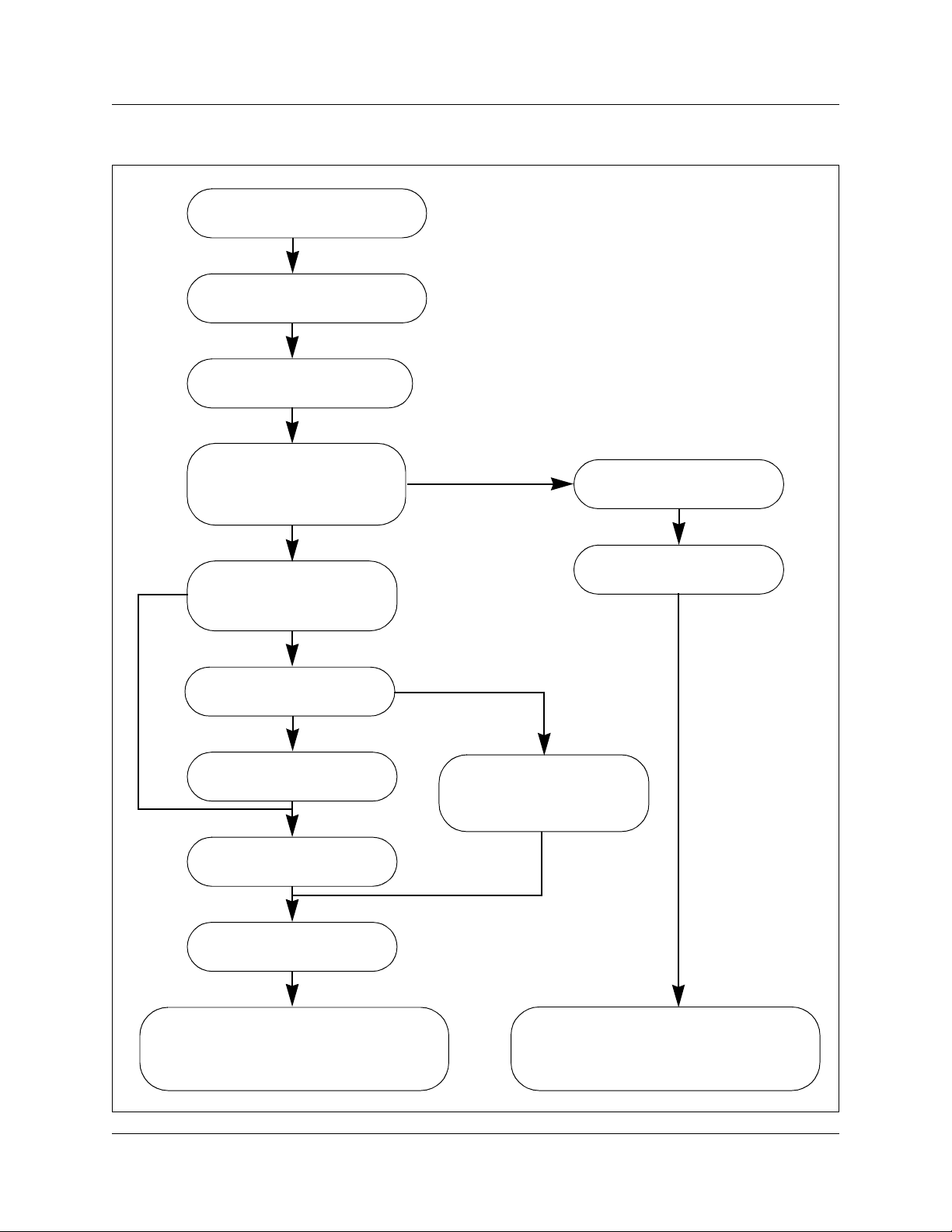
Installing the CallPilot 100/150
Unpack CallPilot 100/150
Mount the CallPilot 100/150
on the wall
Connect the TCM and
power cables
Can you use the default
IP address
192.168.110.10
Change the IP address
serial or Ethernet cable
Change the IP address
using the serial port
Change the IP address
using an Ethernet
crossover cable
Connect the CallPilot
100/150 to the LAN
Run the
Quick Install Wizard
Start CallPilot 100/150 Administration
programming. Refer to the CallPilot
Manager Set Up and Operation Guide.
Yes
No
Ethernet
Serial
Initialize CallPilot 100/150
using CallPilot Manager or
a telephone
Start CallPilot 100/150 Administration
programming. Refer to the CallPilot
Telephone Administration Guide.
Determine the feature
codes
Configure the initial
parameters
Telephone
CallPilot Manger
Installing the CallPilot 100/150 5
CallPilot 100/150 Quick Start Guide
Mounting the CallPilot 100/150 on the wall
1 Attach the wall mount bracket to a secure surface by the two inner holes. Use anchors, as
necessary.
2 Slip the slot on the back (near the top) of the CallPilot 100/150 onto the bracket.
3 Secure the CallPilot 100/150 using a screw in the lower screw hole.
Connecting the CallPilot 100/150
1 Open the CallPilot 100/150 by inserting a flat screwdriver into the slot on the right-hand side
of the door and pressing the tab out of the way.
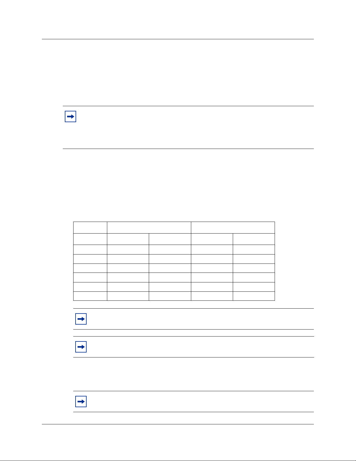
2 Connect a TCM cable to Port A and to Port B.
Table 2 shows the pin out of Port A and Port B.
3 Insert the feature cartridge into the bottom PCMCIA slot of the CallPilot 100/150.
4 Connect the other end of the TCM cables to station ports on your Norstar KSU.
Note: If you are upgrading from a previous voice messaging system (for example,
FlashTalk) to CallPilot 100/150, you must remove the existing Feature Codes for the old
voice messaging system before you install the CallPilot 100/150. For information about
how to remove the existing Feature Codes, refer to CallPilot 150 Feature Codes are
inactive, in the CallPilot 100/150 Installation and Maintenance Guide.
Table 2 Port A and Port B Pinouts
CallPilot 100 CallPilot 150
Pin number Port A Port B Port A Port B
1 no connection no connection no connection no connection
2 no connection no connection TCM 3 TCM 4
3 TCM 1 TCM 2 TCM 1 TCM 2
4 TCM 1 TCM 2 TCM 1 TCM 2
5 no connection no connection TCM 3 TCM 4
6 no connection no connection no connection no connection
Note: On the CallPilot 100, only TCM 1 and TCM 2 are available for use.
Note: It is very important that you ensure that the Feature Cartridge is inserted into
the bottom PCMCIA slot before you power up the CallPilot unit.
Note: Do not connect the Ethernet cable for your LAN to the Ethernet port until you
initialize the CallPilot 100/150.
 Loading...