

Page 1

555-7101-226
555-7101-226
CallPilot
Installation and Configuration
Part 2: 703t Server Hardware Installation
Product release 2.02 Standard 1.01 November 2005
Page 2

P0603578
Page 3

CallPilot
Installation and Configuration
Part 2: 703t Server Hardware Installation
Publication number: 555-7101-226
Product release: 2.02
Document release: Standard 1.01
Date: November 2005
Copyright © 2003 Nortel Networks. All Rights Reserved.
Printed in Canada
Information is subject to change without notice. Nortel Networks reserves the right to make
changes in design or components as progress in engineering and manufacturing may
warrant.
The process of transmitting data and call messaging between the CallPilot server and the
switch or system is proprietary to Nortel Networks. Any other use of the data and the
transmission process is a violation of the user license unless specifically authorized in
writing by Nortel Networks prior to such use. Violations of the license by alternative usage of
any portion of this process or the related hardware constitutes grounds for an immediate
termination of the license and Nortel Networks reserves the right to seek all allowable
remedies for such breach.
This page and the following page are considered the title page, and contain Nortel Networks
and third-party trademarks.
Page 4

*Nortel Networks, the Nortel Networks logo, the Globemark, and Unified Networks, BNR,
CallPilot, DMS, DMS-100, DMS-250, DMS-MTX, DMS-SCP, DPN, Dualmode, Helmsman,
IVR, MAP, Meridian, Meridian 1, Meridian Link, Meridian Mail, Norstar, SL-1, SL-100,
Succession, Supernode, Symposium, Telesis, and Unity are trademarks of Nortel Networks.
3COM is a trademark of 3Com Corporation.
ACCENT is a trademark of Accent Software International Ltd.
ADOBE is a trademark of Adobe Systems Incorporated.
AMDEK is a trademark of Amdek Corporation.
AT&T is a trademark of American Telephone and Telegraph Corporation.
ATLAS is a trademark of Quantum Corporation.
ACCENT is a trademark of Accent Software International Ltd.
ATRIA is a trademark of Pure Atria Corporation.
BLACKBERRY is a trademark of Research in Motion Limited.
CASEWARE is a trademark of Caseware International, Inc.
CONTINUUS is a trademark of Continuus Software Corporation.
CRYSTAL REPORTS is a trademark of Seagate Software Inc.
DEFINITY is a trademark of Avaya Inc.
DIALOGIC, INTEL and VOICEBRIDGE are trademarks or registered trademarks of Intel
Corporation or its subsidiaries in the United States and other countries.
DIVX is a trademark of DivXNetworks, Inc.
EUDORA is a trademark of Qualcomm.
eTrust and InoculateIT are trademarks of Computer Associates Think Inc.
DIRECTX, EXCHANGE.NET, FRONTPAGE, INTERNET EXPLORER, LINKEXCHANGE,
MICROSOFT, MICROSOFT EXCHANGE SERVER, MS-DOS, NETMEETING, OUTLOOK,
POWERPOINT, VISUAL STUDIO, WINDOWS, WINDOWS MEDIA, and WINDOWS NT are
trademarks of Microsoft Corporation.
GROUPWISE and NOVELL are trademarks of Novell Inc.
HITACHI is a trademark of Hitachi Limited.
LOGITECH is a trademark of Logitech, Inc.
LUCENT is a trademark of Lucent Technologies, Inc.
MATRA is a trademark of Matra Hachette.
MCAFFEE and NETSHIELD are trademarks of McAfee Associates, Inc.
MYLEX is a trademark of Mylex Corporation.
NET2PHONE is a trademark of Net2Phone, Inc.
NETOPIA is a trademark of Netopia, Inc.
NETSCAPE COMMUNICATOR is a trademark of Netscape Communications Corporation.
NOTES is a trademark of Lotus Development Corporation.
NORTON ANTIVIRUS and PCANYWHERE are trademarks of Symantec Corporation.
POWERQUEST is a trademark of PowerQuest Corporation.
PROMARK and RHOBOT are trademarks of DMI Promark, Inc.
Page 5

RADISYS is a trademark of Radisys Corporation.
ROLM is a trademark of Siemens ROLM Communications Inc.
SLR4, SLR5, and TANDBERG are trademarks of Tandberg Data ASA.
SONY is a trademark of Sony Corporation.
SYBASE is a trademark of Sybase, Inc.
TEAC is a trademark of TEAC Corporation
UNIX is a trademark of X/Open Company Limited.
US ROBOTICS, the US ROBOTICS logo, and SPORTSTER are trademarks of US
Robotics.
WINAMP is a trademark of Nullsoft, Inc.
WINRUNNER is a trademark of Mercury Interactive Corporation.
WINZIP is a trademark of Nico Mark Computing, Inc.
XEON is a trademark of Intel, Inc.
Part 2: 703t Server Hardware Installation 5
Page 6

Publication history Standard 1.01
6 CallPilot
Page 7

November 2005 Publication history
Publication history
November 2005
October 2003
Standard 1.01 of the CallPilot Installation and
Configuration, Part 2: 703t Server Hardware
Installation is issued for general release.
Standard 1.0 of the CallPilot Installation and
Configuration, Part 2: 703t Server Hardware
Installation is issued for general release.
Part 2: 703t Server Hardware Installation 7
Page 8

Publication history Standard 1.01
8 CallPilot
Page 9

Contents
1 703t server description 11
Server features . . . . . . . . . . . . . . . . . . . . . . . . . . . . . . . . . . . . . . . . . . . . . . 12
Slot assignments . . . . . . . . . . . . . . . . . . . . . . . . . . . . . . . . . . . . . . . . . . . . . 19
IRQ mapping table . . . . . . . . . . . . . . . . . . . . . . . . . . . . . . . . . . . . . . . . . . . 21
Network connectivity . . . . . . . . . . . . . . . . . . . . . . . . . . . . . . . . . . . . . . . . . 23
Supported peripheral devices . . . . . . . . . . . . . . . . . . . . . . . . . . . . . . . . . . . 28
2 Preinstallation requirements 31
Installation overview. . . . . . . . . . . . . . . . . . . . . . . . . . . . . . . . . . . . . . . . . . 32
Unpacking the 703t server . . . . . . . . . . . . . . . . . . . . . . . . . . . . . . . . . . . . . 35
Removing the side cover. . . . . . . . . . . . . . . . . . . . . . . . . . . . . . . . . . . . . . . 37
Inspecting the server interior . . . . . . . . . . . . . . . . . . . . . . . . . . . . . . . . . . . 40
Replacing the side cover . . . . . . . . . . . . . . . . . . . . . . . . . . . . . . . . . . . . . . . 42
Installing the chassis feet . . . . . . . . . . . . . . . . . . . . . . . . . . . . . . . . . . . . . . 44
3 Installing the server and connecting the peripheral
devices 47
Installing the server. . . . . . . . . . . . . . . . . . . . . . . . . . . . . . . . . . . . . . . . . . . 48
Preparing the modem . . . . . . . . . . . . . . . . . . . . . . . . . . . . . . . . . . . . . . . . . 49
Connecting peripherals to the server . . . . . . . . . . . . . . . . . . . . . . . . . . . . . 53
Connecting the server to the ELAN . . . . . . . . . . . . . . . . . . . . . . . . . . . . . . 57
Connecting the server to the CLAN (optional). . . . . . . . . . . . . . . . . . . . . . 59
Installing the Nortel Networks software feature key adapter . . . . . . . . . . . 60
Connecting the server to power . . . . . . . . . . . . . . . . . . . . . . . . . . . . . . . . . 62
Index 67
Part 2: 703t Server Hardware Installation 9
Page 10

Contents Standard 1.01
10 CallPilot
Page 11

Chapter 1
703t server description
In this chapter
Server features 12
Slot assignments 19
IRQ mapping table 21
Network connectivity 23
Supported peripheral devices 28
Part 2: 703t Server Hardware Installation 11
Page 12

703t server description Standard 1.01
Server features
Introduction
This section provides a general overview of the 703t server.
Server dimensions
Height chassis only: 42 cm (16.75 in.)
with chassis feet: 44 cm (17.5 in.)
Width chassis only: 21.5 cm (8.6 in.)
with chassis feet: 32 cm (12.7 in.)
Depth (distance from front to
back)
Clearance
Weight of fully loaded system
with
two SCSI hard drives
six populated boards
CD-ROM drive
floppy drive
tape drive
65 cm (26 in.)
front: 25 cm (10 in.)
rear: 12.5 cm (5 in.)
side: 7.5 cm (3 in.)
Note: Additional side clearance
is required for service.
top: 7.5 cm (3 in.)
approximately 22 kg (46 lb)
12 CallPilot
Page 13
November 2005 703t server description
Front panel features
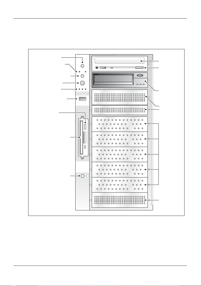
The following diagram shows the 703t server’s front panel features:
Reset button
Network LEDs
Sleep mode
button (not used)
Power button
Status LEDs
USB connector
(not used)
Floppy disk
eject button
Floppy disk drive
Chassis intrusion
detection switch
(not used)
CD-ROM
drive
CD
drawer
eject
button
Tape
drive
Air flow
slots
Hard
drive
bays
Air flow
slot
G101759
Part 2: 703t Server Hardware Installation 13
Page 14

703t server description Standard 1.01
The table below describes the parts that are identified in the preceding
diagram:
Part Function
Reset button Triggers a hardware (cold) reset. Do not use
this button to perform a server restart. Restart
the server as described in “Restarting the
server” in CallPilot Installation and
Configuration Part 1: Installation and
Maintenance Overview (555-7101-210).
Network
controller LEDs
(green)
Left: 10/100Base-T controller LED
(NIC1 10/100 MB: ELAN
for Meridian 1/Succession 1000 connection)
Right: 10/100/1000Base-T controller LED
(NIC2 1 GB: CLAN
for Customer LAN connection)
Sleep mode button Not used
Power button Turns the server’s power on or off.
Status LEDs Indicate when the server is powered up and the
disk drives are active.
Left: hard drive activity LED (not used)
Center: power/sleep LED (green)
Right: status LED (bi-color) indicates
whether the server is functioning properly,
or whether a hardware event has occurred.
USB connector For future use
Floppy disk eject
Ejects the floppy disk.
button
Floppy drive Drive for 3-1/2 inch diskettes.
14 CallPilot
Page 15

November 2005 703t server description
Part Function
IDE CD-ROM drive
(5.25 in.)
CD drive eject
button
Enables you to use the CallPilot software and
documentation CD-ROMs.
Opens the CD-ROM drawer. Push the button
again to close the drawer.
Backup tape drive Allows backup of hard drive data.
Hard drive 1 10,000 rpm hard drive
Hard drive 2 10,000 rpm hard drive
Drive bay Vacant
Drive bay Vacant
Drive bay Vacant
Air flow slot Must remain empty for proper system cooling.
Part 2: 703t Server Hardware Installation 15
Page 16
703t server description Standard 1.01
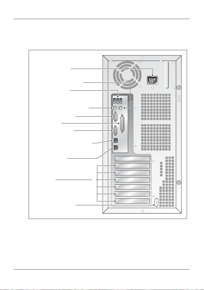
Rear panel diagram
The following diagram shows the 703t server’s rear panel features:
Power connector
PS/2 mouse connector
USB connectors
(not used)
PS/2 keyboard connector
Serial port (COM1)
Parallel port
Monitor connector
10/100/1000Base-T
CLAN Ethernet connector
(NIC2 1 GB)
10/100Base-T
ELAN Ethernet connector
(NIC1 10/100 MB)
PCI slots
Serial port (COM2)
(not installed)
6
5
4
3
2
1
G101760
Note: For more information, see “Slot assignments” on page 19.
16 CallPilot
Page 17

November 2005 703t server description
The table below describes the parts that are identified in the preceding
diagram:
Part Color
AC power supply connector
Not applicable
(450 W non hot-swap power supply)
USB connectors Not applicable
PS/2 keyboard connector Purple
PS/2 mouse connector Green
COM1 serial port connector (9-pin) Teal
Parallel port connector (25-pin) Pink
Monitor connector (15-pin) Blue
10/100/1000Base-T CLAN network connector for
Not applicable
Customer LAN connection (NIC2 1 GB)
Note: For more information, see
“LAN connectivity” on page 26.
10/100Base-T ELAN network connector for
Not applicable
Meridian 1/Succession 1000 connection
(NIC1 10/100 MB)
Note: For more information, see
“LAN connectivity” on page 26.
PCI slots (6)
Four slots are 100 MHz 3.3 V 64-bit PCI slots.
Two slots are 33 MHz 5 V 32-bit PCI slots.
Not applicable
Note: For more information, see
“Slot assignments” on page 19.
COM2 serial port connector slot (not installed) Teal
Part 2: 703t Server Hardware Installation 17
Page 18

703t server description Standard 1.01
Environmental specifications
Environmental condition Specification
Operating temperature 10°C to 35°C (50°F to 95°F)
Maximum rate of change must not
exceed 10
°C (50°F) per hour.
Non-operating (storage)
temperature
Non-operating humidity 95%, non-condensing at 30
Altitude 1829 m (6000 ft)
Electrostatic discharge 15 kV or more
Acoustic noise 50 dBA in a typical office ambient
Operating shock No errors with a half sine wave shock
Handling drop Operational after a free fall from
°C to 70°C (-40°F to 158°F)
-40
°C (86°F)
temperature (18
[64.4
°F to 77°F])
of 2G (with 1 millisecond duration)
45 cm to 60 cm (18 in. to 24 in.)
(depending on weight)
°C to 25°C
18 CallPilot
Page 19

November 2005 703t server description
Slot assignments
Introduction
The slot assignment tables show
the physical location of boards inside the server, relative to other boards
the order in which boards are installed (for example, board #1, 2, 3, and
so on)
how the boards are represented in CallPilot Manager applications (that is,
on the Maintenance Administration page)
the maximum capacity for each switch connectivity
Note: Your server may vary depending on what was ordered from Nortel
Networks; therefore, your server may not have all of the slots populated.
Part 2: 703t Server Hardware Installation 19
Page 20

703t server description Standard 1.01
Slot definition and numbering
In the following table, the term “slot” refers to the available slot openings in
the chassis, not the PCI connectors inside the server.
The slots are numbered from the bottom of the server to the top. Slot 1 is the
bottom slot in the chassis when the chassis is standing upright.
CallPilot-assigned
Slot number
board label
a
Slot 7 Not used Not used
Description
PCI slot 6
BRD06 RAID card
(full length)
PCI slot 5
BRD05 Not used
(full length)
PCI slot 4
BRD04 MPB96 board
(full length)
PCI slot 3
BRD03 Not used
(full length)
PCI slot 2
BRD02 Not used
(full length)
PCI slot 1
BRD01 Not used
(full length)
a. In CallPilot Manager applications, the CallPilot-assigned board label may
appear. This label corresponds to the slot number. For example, BRD01 refers to
the board in slot 1.
20 CallPilot
Page 21

November 2005 703t server description
IRQ mapping table
The following table lists the assignments for each Interrupt Request (IRQ).
You do not need this information for installation, but it may be useful for
troubleshooting.
Interrupt I/O APIC level Slot or device
INTR INT0 Processor interrupt
IRQ0 INT2 Timer (from PIIX4)
IRQ1 INT1 PS/2 keyboard controller
IRQ2 Not
applicable
IRQ3 INT3 Onboard serial port B (COM2)
IRQ4 INT4 Onboard serial port A (COM1)
IRQ5 INT5 Available
IRQ6 INT6 Floppy disk drive controller
IRQ7 INT7 Parallel port 1(LPT1)
IRQ8 INT8 Real Time Clock
IRQ9 INT9 Available
IRQ10 INT10 Available
IRQ11 INT11 Available
IRQ12 INT12 PS/2 mouse
IRQ13 INT13 Internal/reserved
Internal/reserved
Note: IRQ2 is actually shared with IRQ9 as a
cascade interrupt to support IRQs 8–15.
Part 2: 703t Server Hardware Installation 21
Page 22

703t server description Standard 1.01
Interrupt I/O APIC level Slot or device
IRQ14 INT14 IDE controller
IRQ15 INT15 Available
22 CallPilot
Page 23

November 2005 703t server description
Network connectivity
Introduction
This section describes how the 703t server can be integrated into your
network. The integration depends on the type of switch you are using.
Refer to:
“Sample network setup: Meridian 1” on page 24
“Sample network setup: Succession 1000” on page 25
ATTENTION
To secure the CallPilot server from unauthorized access,
ensure that the CallPilot network is inside your
organization’s firewall.
Part 2: 703t Server Hardware Installation 23
Page 24

703t server description Standard 1.01
Sample network setup: Meridian 1
The Meridian 1 switch can be one of the following:
Option 11C or Option 11C Mini using fiber connections
Option 51C
Option 61C
Options 81 and 81C
The following diagram shows a CallPilot 703t server network setup with a
Meridian 1 switch.
Desktop
client PC
Meridian 1 switch
MGate
card
Desktop
client PC
Customer LAN (optional)
Modem
CallPilot server
MPB board
Embedded LAN
Laptop
Web-enabled
administrative
PC
Router or
Ethernet
switch
(optional)
Web-enabled
administrative
PC
G101626
24 CallPilot
Page 25

November 2005 703t server description
Sample network setup: Succession 1000
The following diagram shows a CallPilot 703t server network setup with a
Succession 1000 system:
Internet
Telephony
Gateway
Line Card
Succession
1000 Call
Server
i2004
Internet
phonesets
Telephony LAN/Customer LAN (10/100/1000Base-T)
Succession 1000
Media Gateway
Expansion
CE-MUX
Internet
Telephony
Gateway
Line Card
DS-30x
Succession
1000 Media
Gateway
Embedded LAN (10/100Base-T)
Web-enabled
CallPilot
administrative
PC
MGate
card
Modem
CallPilot
server
MPB board
Desktop
client
PC
Router or
Ethernet
switch
(optional)
Optivity
Telephony
Manager
PC
Laptop
Web-enabled
CallPilot
administrative
PC
G101636
Part 2: 703t Server Hardware Installation 25
Page 26

703t server description Standard 1.01
In the previous diagram, the telephony LAN (TLAN) provides IP
connectivity between the Succession 1000 system and the i2004 Internet
phonesets. The connection between the Call Server and Media Gateway can
be point-to-point, or it can be through the LAN, if the system is installed in a
distributed data network.
For information about the Succession 1000 system and i2004 Internet
phoneset bandwidth and network requirements, refer to the Succession 1000
Planning and Installation Guide (NTP 553-3023-210).
Switch connectivity
For more details about how the 703t server and switch connection is
established, refer to the switch and server setup document for your switch:
CallPilot Installation and Configuration Part 3: Succession 1000 System
and CallPilot Server Configuration (555-7101-510)
CallPilot Installation and Configuration Part 3: Meridian 1 and
CallPilot Server Configuration (555-7101-222)
LAN connectivity
The 703t server contains two Ethernet controllers on the motherboard that
provide the following:
10/100Base-T Ethernet network connectivity to the ELAN
For information about the ELAN’s purpose and requirements, see “About
the ELAN” in CallPilot Installation and Configuration Part 1:
Installation and Maintenance Overview (555-7101-210).
10/100/1000Base-T Ethernet connectivity to the CLAN
The CLAN is an optional connection that provides data connectivity
among desktop and web messaging clients, administrative PCs, and the
CallPilot server.
See “Rear panel diagram” on page 16 to identify the location of network
interface connectors.
26 CallPilot
Page 27

November 2005 703t server description
Network requirements
Appropriate networking equipment must be available for both the CLAN
and ELAN.
The CLAN and ELAN must be properly configured for correct CallPilot
operation. To ensure correct configuration, Nortel Networks recommends
that you consult a network specialist.
ATTENTION
For important considerations about using the ELAN in
your network, see “About the ELAN” in CallPilot
Installation and Configuration Part 1: Installation and
Maintenance Overview (555-7101-210).
Remote access connectivity
The RS-232 COM1 connector on the rear of the 703t server provides the
connection to an external dial-up modem. The modem allows administrators
and technical support personnel to administer the 703t server from a remote
location.
pcAnywhere is used to establish a remote access connection to the server.
Part 2: 703t Server Hardware Installation 27
Page 28

703t server description Standard 1.01
Supported peripheral devices
Introduction
This section identifies external devices that are supported by the 703t
server. The following table describes the supported peripheral devices:
Device Description
Modem A 56 Kbps external modem (NTRH9078 in North
America only) provides remote access to the 703t server.
The modem connects to the RS-232 COM1 connector on
the rear of the server.
Since the modem is an external device, it requires its own
AC power source referenced to the same ground as the
703t server and the switch to which it is connected.
Ethernet hub A 10Base-T Ethernet hub provides the ELAN connection
between the 703t server and the Meridian 1 switch or
Succession 1000 system. The customer can supply a hub
from third-party vendors or purchase the 3Com
10Base-T Ethernet hub (NTRH9017) from Nortel
Networks.
Since the hub is an external device, it requires an AC
power source referenced to the same ground as the 703t
server and the switch to which it is connected.
ATTENTION
If a hub is required or used, it must be located at least 6
m (20 ft) away from the 703t server. This ensures
compliance with EMC requirements.
28 CallPilot
Page 29

November 2005 703t server description
Device Description
Monitor, keyboard,
and mouse
15-in. monitor: NTRH9011
Since the monitor is an external device, it requires its
own AC power source referenced to the same ground
as the 703t server and the switch to which it is
connected.
Keyboard: NTRH9013
Mouse: NTRH9014
Part 2: 703t Server Hardware Installation 29
Page 30

703t server description Standard 1.01
30 CallPilot
Page 31

Chapter 2
Preinstallation requirements
In this chapter
Installation overview 32
Unpacking the 703t server 35
Removing the side cover 37
Inspecting the server interior 40
Replacing the side cover 42
Installing the chassis feet 44
Part 2: 703t Server Hardware Installation 31
Page 32

Preinstallation requirements Standard 1.01
Installation overview
Introduction
This section provides an overview of the steps required to install the 703t
server and peripheral devices. For detailed instructions, see Chapter 3,
“Installing the server and connecting the peripheral devices.”
When you are finished, continue with the switch and server setup as
described in the document for your switch:
CallPilot Installation and Configuration Part 3: Succession 1000 System
and CallPilot Server Configuration (555-7101-510)
CallPilot Installation and Configuration Part 3: Meridian 1 and
CallPilot Server Configuration (555-7101-222)
Installation checklist
Step Description Check
1 Ensure that you have reviewed the “Installing CallPilot” section
❒
in CallPilot Installation and Configuration Part 1: Installation
and Maintenance Overview (555-7101-210), and completed
stage 1 of the “Installation checklist.”
2 Unpack the server, and ensure you have all the items you need
❒
(see page 35).
Complete the following checklists that are provided in
CallPilot Installation and Configuration Part 1: Installation
and Maintenance Overview (555-7101-210):
“CallPilot software media and documentation checklist”
“CallPilot server hardware checklist”
3 Remove the server cover, and inspect the interior (see pages 37
❒
and 40).
32 CallPilot
Page 33

November 2005 Preinstallation requirements
Step Description Check
4 Replace the server cover. ❒
5 Place the 703t server in the chosen location (see page 48). ❒
6 Set the DIP switches on the modem (see page 51). ❒
7 Connect the 703t server and devices as follows:
Connect the monitor, keyboard, and mouse (see page 53). ❒
Connect the modem (see page 55). ❒
Connect the 703t server to the ELAN hub (see page 57).
❒
ATTEN TIO N
If a hub is required or used, it must be located at least 6 m
(20 ft) away from the 703t server. This ensures compliance
with EMC requirements.
Connect the 703t server to the CLAN hub (optional); (see
❒
page 59).
ATTEN TIO N
If a hub is required or used, it must be located at least 6 m
(20 ft) away from the 703t server. This ensures compliance
with EMC requirements.
Install the software feature key adapter (see page 60). ❒
Connect the power cords for all devices, and then power
❒
them up (see page 62).
8 Start the 703t server (see page 64). ❒
Part 2: 703t Server Hardware Installation 33
Page 34

Preinstallation requirements Standard 1.01
Conventions for warnings
You may encounter the following types of warnings in this guide. Do not
ignore them.
DANGER
.
.
.
ATTENTION
Risk of electric shock
Warns you of an immediate electrical hazard, which, if not
avoided, will result in shock, serious injury, or death.
WARNING
Risk of personal injury
Warns you of a situation in which you can be injured if
instructions are not followed exactly as stated.
CAUTION
Risk of data loss or equipment damage
Alerts you to situations where data can be lost or damaged,
equipment can be damaged, actions can result in service
interruption, and productive time can be lost.
Provides information that is essential to the completion
of a task.
34 CallPilot
Page 35

November 2005 Preinstallation requirements
Unpacking the 703t server
Introduction
Follow this procedure to unpack the server and peripherals.
WARNING
.
Risk of personal injury
The 703t CallPilot server weighs approximately 22 kg (46 lb)
as shipped from manufacturing. If necessary, and to prevent
personal injury, ask someone to help you unpack and position
the server.
To unpack the equipment
ATTENTION
1 Carefully open the cardboard carton containing the server.
2 Remove the server from the carton and set it on the floor.
3 Carefully open the cartons containing the monitor, keyboard, mouse,
modem, and ELAN hub (if supplied), and set the peripherals aside.
As you unpack each item, check it off against the
packing list, as well as against the following checklists
provided in CallPilot Installation and Configuration
Part 1: Installation and Maintenance Overview (5557101-210):
“CallPilot software media and documentation
checklist”
“CallPilot server hardware checklist”
4 Put all manuals, CD-ROMs, operating system disks, any disks for
peripherals, and the Windows NT emergency repair disk in a safe place.
Part 2: 703t Server Hardware Installation 35
Page 36

Preinstallation requirements Standard 1.01
5 Save all packing materials and cartons in case you must return any
equipment to the carrier.
What’s next?
Remove the server cover so that you can inspect the interior of the server.
See “Removing the side cover” on page 37.
36 CallPilot
Page 37

November 2005 Preinstallation requirements
Removing the side cover
Introduction
This section describes how to remove the server’s side cover so that you can
work with the interior components. The side cover is on the server’s left side
when the front of the server is facing you.
To remove the side panel
WARNING
.
Be careful when you handle the sharp edges of the side panel
and chassis to prevent personal injury.
Risk of personal injury
CAUTION
Risk of equipment damage
.
Use an ESD wrist strap to protect static-sensitive
components.
Place the server on its side to prevent the server from
accidentally falling over. This provides greater stability. If
you attempt to work with the server in its standing position,
it may tip over when you work with the interior
components.
Part 2: 703t Server Hardware Installation 37
Page 38

Preinstallation requirements Standard 1.01
The following diagram shows how to remove the side panel. See the
instructions for removal below.
1
2
3
G101761
1 Place the server on its side on your working surface.
2 Turn the two thumbscrews on the back of the server counter-clockwise to
loosen them.
Note: The thumbscrews are not removable.
Note: If a removable screw is present, remove it. This screw secures the
cover to the server during shipping.
3 Place your fingertips in the depression on the side cover, and then as
you apply pressure, pull the cover approximately 2.5 cm (1 in.) away from
the front of the server until it stops.
38 CallPilot
Page 39

November 2005 Preinstallation requirements
4 Use one hand to pull the top edge of the cover away from the server to
disengage the top row of tabs on the cover from the notches in the
chassis.
5 Use both hands to lift the cover upward to disengage the bottom row of
tabs from the notches in the chassis.
6 Set the cover aside.
7 Continue with “Inspecting the server interior” on page 40.
Part 2: 703t Server Hardware Installation 39
Page 40

Preinstallation requirements Standard 1.01
Inspecting the server interior
Introduction
Before you install the server, you should perform a visual inspection for
loose components, foreign matter, or shipping damage inside the server.
CAUTION
.
Risk of equipment damage
When working with interior components, use an ESD wrist
strap to protect static-sensitive components.
To inspect the server interior
1 Ensure that all the cards are fully seated on the baseboard.
2 Check for any loose wires or foreign objects, such as loose screws,
inside the chassis.
3 Review the slot locations (see “Rear panel diagram” on page 16).
4 Do one of the following:
IF THEN
you observe
any damage
components have
become loose
contact your Nortel Networks technical
support representative.
secure them. Then replace the server
cover and proceed with the hardware
installation.
Refer to the procedures in CallPilot
Installation and Configuration Part 5:
703t Server Maintenance and
Diagnostics (555-7101-227).
40 CallPilot
Page 41

November 2005 Preinstallation requirements
IF THEN
you are satisfied that the
703t server has arrived at
your site undamaged
replace the server cover.
For instructions, see “Replacing the side
cover” on page 42.
Part 2: 703t Server Hardware Installation 41
Page 42

Preinstallation requirements Standard 1.01
Replacing the side cover
Introduction
When you are satisfied that the server was not damaged during shipment,
reinstall the side cover.
To replace the side cover
CAUTION
.
Risk of equipment damage
Ensure that there are no tools or loose parts inside the server
chassis before replacing the side cover.
1 Align the right edge of the server’s side cover with the inside ledge at the
front of the server.
2 Ensure that the cover lays flat along the side of the server.
3 Insert the tabs along the top and bottom edges of the server’s cover
inside the slots along the top and bottom of the server.
4 Push the cover towards the front of the server until the tabs firmly
engage in the chassis.
Note: When correctly engaged, the cover clicks into place.
5 Tighten the two thumbscrews on the back of the server.
42 CallPilot
Page 43

November 2005 Preinstallation requirements
The following diagram shows how to: 1) align the tabs, 2) engage the cover
and 3) tighten the thumbscrews.
Top and
bottom slots
in chassis
3
Top and
bottom tabs
on cover
1
2
G101762
What’s next?
If you want to install the chassis feet on the bottom of the server, continue
with “Installing the chassis feet” on page 44. Otherwise, continue with the
hardware installation. For more information, see “Installation checklist” on
page 32.
Part 2: 703t Server Hardware Installation 43
Page 44

Preinstallation requirements Standard 1.01
Installing the chassis feet
Introduction
You can install feet on the bottom of the server. The feet stabilize the server
and will help prevent the server from accidentally falling over on its side.
To install the chassis feet
Towards
back of
server
Towards
front of
server
G101782
44 CallPilot
Page 45

November 2005 Preinstallation requirements
1 Ensure that the server is laying on its side, supported to give the server
bottom four to five inches clearance above the work surface.
2 Attach the feet as shown in the preceding diagram.
Use four screws to attach each foot to the chassis. The holes in the feet
line up with only one set of holes in the chassis, as follows:
front foot: The middle hole is towards the front of the chassis.
back foot: The middle hole is towards the back of the chassis.
3 Place the server on its feet.
What’s next?
Continue with the hardware installation. For more information, see
“Installation checklist” on page 32.
Part 2: 703t Server Hardware Installation 45
Page 46

Preinstallation requirements Standard 1.01
46 CallPilot
Page 47

Chapter 3
Installing the server and connecting the peripheral devices
In this chapter
Installing the server 48
Preparing the modem 49
Connecting peripherals to the server 53
Connecting the server to the ELAN 57
Connecting the server to the CLAN (optional) 59
Installing the Nortel Networks software feature key adapter 60
Connecting the server to power 62
Part 2: 703t Server Hardware Installation 47
Page 48

Installing the server and connecting the peripheral devices Standard 1.01
Installing the server
Introduction
Before you install the 703t server, ensure that the chosen location meets the
requirements identified on the “Site inspection checklist” provided in
CallPilot Installation and Configuration Part 1: Installation and
Maintenance Overview (555-7101-210).
To install the server
1 Place the 703t server in its chosen location.
Note: The server must be placed within 20 m (60 feet) of the Meridian 1
switch or Succession 1000 system.
Note: The DS30X cable that connects MPB96 board
20 m (60 feet) long. This allows the server to be placed in a different
room from the Meridian 1 switch or Succession 1000 system.
2 Connect peripheral devices as described in the remainder of this
chapter.
s to MGate cards is
48 CallPilot
Page 49

November 2005 Installing the server and connecting the peripheral devices
Preparing the modem
Introduction
You require a modem to support remote dial-up access to the CallPilot
server. The modem also enables Nortel Networks technical support to
connect to your CallPilot server for troubleshooting purposes. Nortel
Networks connects to your server only when you request technical
assistance.
Required equipment
To install the modem, you need the following equipment:
an analog external modem that includes
an RJ-11 analog phone cord
a power adapter cord
US Robotics 56 Kbps modem (NTRH9078) (North America only)
a 25-pin male to 9-pin female shielded serial cable for your modem
(A0841984)
an analog line jack
tweezers, or a screwdriver small enough to use to adjust DIP switches
Modem DIP switches
Set the modem DIP switches before you connect the modem to the CallPilot
server.
Note: This section applies only to the US Robotics 33.6 or 56 Kbps external
Sportster modem. If your modem is different, refer to the documentation for
your modem.
Part 2: 703t Server Hardware Installation 49
Page 50

Installing the server and connecting the peripheral devices Standard 1.01
The following diagram shows the key components of the external modem,
including the location and required settings of the DIP switches:
RJ-11
connection
Switch positions:
OFF
DIP
switches
1234567 8
ON
12345678
Serial cable
(RS-232)
connection
Power
connection
G101445
50 CallPilot
Page 51

November 2005 Installing the server and connecting the peripheral devices
To set the modem DIP switches
Use a pair of tweezers or a small screwdriver to set the DIP switches as
described in the “Change to” column of the following table:
Note: ON is down. OFF is up.
DIP
switch
Default
setting
Change
to Function
1 OFF OFF Data Terminal Ready (DTR) override
OFF: Normal DTR operations. (The
computer must provide a DTR signal for the
modem to accept commands. If DTR is
dropped, the call is terminated.)
ON: The modem ignores DTR (override).
2 OFF OFF Verbal/numeric result codes
OFF: Verbal (word) results.
ON: Numeric results.
3 ON ON Result code display
OFF: Suppresses result codes.
ON: Enables result codes.
4 OFF OFF Command mode local echo suppression
OFF: Displays keyboard commands.
ON: Suppresses echo.
5 ON ON Auto answer suppression
OFF: The modem answers on the first ring
or later, as specified in user-defined
nonvolatile memory (NVRAM).
ON: Disables auto answer.
Part 2: 703t Server Hardware Installation 51
Page 52

Installing the server and connecting the peripheral devices Standard 1.01
DIP
switch
Default
setting
Change
to Function
6 OFF OFF Carrier Detect (CD) override
OFF: The modem sends a CD signal when it
connects with another modem; it drops the
CD on disconnect.
ON: CD is always ON (override).
7 OFF OFF Power-on and ATZ reset software defaults
OFF: Loads Y or Y1 configuration from
NVRAM.
ON: Loads &F0-Generic template from
read-only memory (ROM).
8 ON ON AT command set recognition
OFF: Disables command recognition (dumb
mode).
ON: Enables recognition (smart mode).
What’s next?
Continue with “Connecting peripherals to the server” on page 53.
52 CallPilot
Page 53

November 2005 Installing the server and connecting the peripheral devices
Connecting peripherals to the server
Introduction
This section describes how to connect the monitor, keyboard, mouse, and
modem to the server.
Rear panel
The peripheral device connection panel at the back of the server provides a
legend that shows the symbol for each peripheral device and which
connector to use.
CAUTION
.
Risk of system failure
You can install or use only Nortel Networks-approved
peripheral devices on your server. Installation or use of
unapproved peripheral devices can result in system failure.
Part 2: 703t Server Hardware Installation 53
Page 54

Installing the server and connecting the peripheral devices Standard 1.01
The diagram below shows the connectors for the power cord and the
peripheral devices on the 703t server.
Power connector
PS/2 mouse connector
USB connectors
(not used)
PS/2 keyboard connector
Serial port (COM1)
Parallel port
Monitor connector
10/100/1000Base-T
CLAN Ethernet connector
(NIC2 1 GB)
10/100Base-T
ELAN Ethernet connector
(NIC1 10/100 MB)
PCI slots
Serial port (COM2)
(not installed)
6
5
4
3
2
1
G101760
54 CallPilot
Page 55

November 2005 Installing the server and connecting the peripheral devices
To connect the mouse, keyboard, and monitor to the server
1 Place the monitor, keyboard, and mouse in the same location as the
server.
2 Plug the keyboard and mouse into the appropriate PS/2 connectors on
the chassis rear panel. See the diagram on page 54.
3 Plug in the monitor connector. Tighten the screws on the connector.
4 Connect the power cord to the monitor, and plug the other end into a wall
receptacle or power bar.
5 Turn on the monitor.
To connect the modem to the server
1 Ensure that the modem’s AC power cord is not plugged in.
2 Connect the large 25-pin male connector to the back of the modem.
Tighten the connector screws.
3 Connect the 9-pin female connector to COM1 port at the rear of the
server. Tighten the connector screws.
4 Connect one end of the telephone cable to the modem RJ-11 jack
labeled LINE.
5 Connect the other end of the telephone cable to the RJ-11 jack in the
wall.
6 Connect the power cord to the modem, and plug the other end into a wall
receptacle or power bar.
7 Turn on the modem.
What’s next?
Continue with “Connecting the server to the ELAN” on page 57.
Part 2: 703t Server Hardware Installation 55
Page 56

Installing the server and connecting the peripheral devices Standard 1.01
Connect the server to the ELAN and CLAN hubs (if applicable).
IF the server will THEN
be connected to the ELAN continue with page 57.
be connected only to a CLAN continue with page 59.
not be connected to either the
ELAN or CLAN
continue with installing the software
feature key adapter (dongle). See page
60.
56 CallPilot
Page 57

November 2005 Installing the server and connecting the peripheral devices
Connecting the server to the ELAN
Introduction
Connect the CallPilot server to the Meridian 1 switch or Succession 1000
system using the Embedded LAN (ELAN).
ATTENTION
For important considerations about using the ELAN in
your network, see “About the ELAN” in CallPilot
Installation and Configuration Part 1: Installation and
Maintenance Overview (555-7101-210).
ATTENTION
If a hub is required or used, it must be located at least 6 m
(20 ft) away from the 703t server. This ensures compliance
with EMC requirements.
To connect the server to the ELAN
1 Locate the ELAN Ethernet connector on the back of the server.
Note: The ELAN connector is labeled as NIC1 10/100 MB. For the
connector location, see the diagram on page 54.
2 Connect an RJ-45 network cable from the ELAN hub to the server’s
ELAN connector.
Note: The ELAN hub is optional if you use a cross-over network cable to
make a direct point-to-point connection from the server to the switch.
However, if you choose to establish a direct point-to-point ELAN
connection, no other device can connect to the ELAN.
Part 2: 703t Server Hardware Installation 57
Page 58

Installing the server and connecting the peripheral devices Standard 1.01
3 At the switch, connect the ELAN network cable to an MAU (Ethernet)
transceiver. Then complete the connection from the transceiver to the
switch.
DANGER
.
What’s next?
IF the server will THEN
be connected to a CLAN continue with page 59.
not be connected to a CLAN continue with installing the software
Risk of fire hazard
The NTRH9069 MAU is not suitable for installation in ducts,
plenums, or other spaces used for environmental air. Do
not install it above a false ceiling or below a raised floor,
unless it can be confirmed that these spaces are not used
to convey environmental air.
feature key adapter (dongle). See page
60.
58 CallPilot
Page 59

November 2005 Installing the server and connecting the peripheral devices
Connecting the server to the CLAN (optional)
Introduction
This section provides instructions to connect the server to the Customer
LAN (CLAN).
Note: The CLAN connection is optional. However, connection to a CLAN
is required for support of desktop and web messaging users, or
administration by means of a web-enabled PC.
ATTENTION
If a hub is required or used, it must be located at least 6 m
(20 ft) away from the 703t server. This ensures compliance
with EMC requirements.
To connect the server to the CLAN
1 Locate the CLAN connector on the back of the server.
Note: The CLAN connector is labeled as NIC2 1GB. For the connector
location, see the diagram on page 54.
2 Connect an RJ-45 network cable from the CLAN hub to the CLAN
connector.
What’s next?
Continue with “Installing the Nortel Networks software feature key adapter”
on page 60.
Part 2: 703t Server Hardware Installation 59
Page 60

Installing the server and connecting the peripheral devices Standard 1.01
Installing the Nortel Networks software feature key adapter
Introduction
The software feature key is a security device that stores the unique serial
number of the server. The feature key is embedded in the Nortel Networks
software feature key adapter, which plugs into the parallel port.
An illustration of the software feature key embedded in the software feature
key adapter is shown below:
Software
feature key
G101738
60 CallPilot
Page 61

November 2005 Installing the server and connecting the peripheral devices
Requirements
For installation, you require a Phillips No. 1 screwdriver.
To install the software feature key adapter
1 Ensure that there is no cable connected to the parallel port.
Note: The parallel port is also known as the printer port or LPT1. It is
located at the back of the server. See the diagram on page 54.
2 Plug the male end of the adapter into the parallel port.
3 Tighten the connector screws.
What’s next?
Continue with “Connecting the server to power” on page 62.
Part 2: 703t Server Hardware Installation 61
Page 62

Installing the server and connecting the peripheral devices Standard 1.01
Connecting the server to power
Before you begin
Ensure that proper power and grounding are available for all the power
outlets serving the CallPilot server and its associated peripherals. Power for
these devices must be wired and fused independently of all other receptacles
and referenced to the same ground as the PBX system.
A qualified electrician must implement the single-point ground reference as
required among the power outlets of the CallPilot server, its associated
peripherals, and the power outlets of the switch.
Provide a sufficient number of properly grounded power outlets or power
bars for all equipment.
62 CallPilot
Page 63

November 2005 Installing the server and connecting the peripheral devices
Before you connect the server to the power source, review the following
diagram (and the warning that follows) to ensure that all peripheral
hardware devices are in place:
CallPilot
server
Video
Mouse
Keyboard
Monitor
AC
power
RJ-45
ELAN hub
(M1 or
Succession
1000 only)
AC
power
AC
power
source
RJ-45 RS-232
CLAN hub
(optional)
AC
power
Modem
AC
power
G101637
Part 2: 703t Server Hardware Installation 63
Page 64

Installing the server and connecting the peripheral devices Standard 1.01
WARNING
.
Risk of personal injury and risk of hardware failure
You must connect the power outlets that are used by the
CallPilot server and its peripheral devices to the same
single-point ground reference as the one used by the
Meridian 1 switch or Succession 1000 system with MGate
cards connected to the CallPilot server.
If this requirement is not met, power transients can cause
personal injury, hardware failure, or both. For more
information on single-point grounding requirements, refer to
the discussion of safety guidelines in CallPilot Installation and
Configuration Part 1: Installation and Maintenance Overview
(NTP 555-7101-210).
To connect the server to power
1 Plug the server’s AC power cord into the server’s rear panel.
2 Plug the other end into a wall receptacle or power bar.
To start the server
1 Press the server’s power switch to start the server.
2 Observe the Power-On Self-Test (POST) and initialization messages on
the monitor.
3 When the following menu appears on the monitor, choose the first option
to start Windows NT:
OS Loader V4.00
Please select the operating system to start:
Windows NT Server Version 4.00
Windows NT Server Version 4.00 [VGA mode]
64 CallPilot
Page 65

November 2005 Installing the server and connecting the peripheral devices
Use <arrow up> and <arrow down> to move the highlight
to your choice
Press Enter to choose
Seconds until highlighted choice will be started
automatically 5
The Windows NT startup sequence begins.
4 Ensure that the Windows NT logon window appears on the monitor.
Note: If the Windows NT logon window does not appear, refer to
CallPilot Installation and Configuration Part 5: 703t Server Maintenance
and Diagnostics (555-7101-227) for troubleshooting instructions.
What’s next?
If Windows NT started successfully, proceed with switch and server setup as
described in the document for your switch:
CallPilot Installation and Configuration Part 3: Succession 1000 System
and CallPilot Server Configuration (555-7101-510)
CallPilot Installation and Configuration Part 3: Meridian 1 and
CallPilot Server Configuration (555-7101-222)
Part 2: 703t Server Hardware Installation 65
Page 66

Installing the server and connecting the peripheral devices Standard 1.01
66 CallPilot
Page 67

Index
Numerics
703t server
CLAN
connection, establishing
connector 17
connections
establishing
power 62
dimensions 12
ELAN
connection, establishing
environmental specifications 18
feet, installing 44–45
front panel, description 13–15
hard drive bays 15
installing 48
interior inspection 40–41
IRQ assignments 21
LEDs 14
PCI slots 17
peripheral device connections, diagram
62
peripheral devices, connecting 53
power connection, establishing 64
rear panel, description 53–54
side cover
removing
replacing 42–43
slot assignments 20
slot locations 16
starting 64
unpacking 35
62
37–39
59
57–58
A
adapter, software feature key 60
B
board labels, CallPilot Manager 20
C
checklist, installation 32–33
CLAN
connecting server to
server connector 17
COM1 connection, description 27
connectivity
CLAN
26
ELAN 26
remote access 27
Customer LAN See CLAN
59
D
DC power input 55
devices, peripheral 28
keyboard 29
modem 28
monitor 29
mouse 28, 29
diagrams
CallPilot network connections
Meridian 1
24
Part 2: 703t Server Hardware Installation 67
Page 68

Index Standard 1.01
Succession 1000 25
front panel 13
modem 50
rear panel 16, 54
server connections, peripheral devices 62
server feet, installing 44
side cover
removing
replacing 43
software feature key adapter 60
TLAN (Succession 1000) 25
dimensions, 703t server 12
DIP switches, setting modem 51–52
dongle 60
38
E
ELAN
connecting server to
Embedded LAN See ELAN
environmental specifications, 703t server
Ethernet hub 28
57–58
F
fax modem
diagram
required equipment 49
front panel, description 13–15
50
K
keyboard
connecting to the server
description 29
55
L
LAN connections, description 26–27
LEDs
network controller
system status 14
14
M
Meridian 1, CallPilot server network setup
24
modem 28
connecting to the server 55
18
description 28
diagram 50
DIP switches, description 49–50
DIP switches, setting 51–52
required equipment 49
monitor
connecting to the server
description 29
mouse
connecting to the server
description 28, 29
55
55
H
hard drive bays 15
I
interior, inspecting server 40–41
IRQ assignments, 703t server 21
68 CallPilot
N
network
controllers
protocols 26–27
setup, CallPilot
Meridian 1
Succession 1000 25
26–27
24
Page 69

November 2005 Index
P
part numbers
keyboard
modem 28
monitor 29
mouse 28, 29
PCI slots 17
peripheral devices 28
connecting to the server 53
keyboard 29
modem 28
monitor 29
mouse 28, 29
power
connecting server to
grounding, requirement 64
protocols, supported network 26–27
29
64
R
rear panel, description 16–17, 53–54
remote access connectivity 27
RS-232 connection 27
S
serial number 60
server
CLAN
connection, establishing
connector 17
connections
establishing
power 62
dimensions 12
ELAN
connection, establishing
environmental specifications 18
feet, installing 44–45
front panel, description 13–15
hard drive bays 15
62
59
57–58
installing 48
interior inspection 40, 40–41
IRQ assignments 21
LEDs 14
PCI slots 17
peripheral device connections, diagram
62
peripheral devices, connecting 53
power connection establishing 64
rear panel, description 53–54
serial number 60
side cover
removing
replacing 42–43
slot assignments 20
slot locations 16
starting 64
unpacking 35
side cover
removing
replacing 42–43
single-point grounding, power requirement
slot assignments 20
slot locations 16
software feature key 60
software feature key adapter
description
installing 61
specifications, environmental 18
Succession 1000, CallPilot network setup 25
switches, setting modem DIP 51–52
37–39
37–39
64
60
T
telephony LAN See TLAN
TLAN, diagram
25
U
unpacking 35
Part 2: 703t Server Hardware Installation 69
Page 70

Index Standard 1.01
W
warnings, conventions 34
70 CallPilot
Page 71

Page 72

CallPilot
Installation and Configuration
Part 2: 703t Server Hardware Installation
Copyright © 2003 Nortel Networks. All Rights Reserved.
Information is subject to change without notice. Nortel Networks reserves the right to make
changes in design or components as progress in engineering and manufacturing may
warrant.
The process of transmitting data and call messaging between the CallPilot server and the
switch or system is proprietary to Nortel Networks. Any other use of the data and the
transmission process is a violation of the user license unless specifically authorized in
writing by Nortel Networks prior to such use. Violations of the license by alternative usage of
any portion of this process or the related hardware constitutes grounds for an immediate
termination of the license and Nortel Networks reserves the right to seek all allowable
remedies for such breach.
Publication number: 555-7101-226
Product release: 2.02
Document release: Standard 1.01
Date: November 2005
Printed in Canada
 Loading...