

Page 1

CallPilot 100/150 Quick Start Guide
www.nortelnetworks.com
© November 19, 2004
N0008008 02
Page 2

2 Regulatory information for CallPilot 100/150
Regulatory information for CallPilot 100/150
Copyright © 2004 Nortel Networks
All rights reserved. 2004.
The information in this document is subject to change without notice. The statements, configurations, technical data, and
recommendations in this document are believed to be accurate and reliable, but are presented without express or implied warranty.
Users must take full responsibility for their applications of any products specified in this document. The information in this
document is proprietary to Nortel Networks NA Inc.
Trademarks
NORTEL NETWORKS is a trademark of Nortel Networks.
All other trademarks and registered trademarks are the property of their respective owners.
Statement of conditions
In the interest of improving internal design, operational function, and/or reliability, Nortel Networks NA Inc. reserves the right to
make changes to the products described in this document without notice.
Nortel Networks NA Inc. does not assume any liability that may occur due to the use or application of the product(s) or circuit
layout(s) described herein.
Regulatory Requirements
CallPilot 100/150 meets the CSPR22 Class A regulatory requirements.
FCC Regulations
This equipment complies with Federal Communications Commission Rules and Regulations Part 68 when connected to a Norstar
switch. This equipment does not connect directly to the public switched telephone network.
DOC Regulations
This equipment complies with the Canadian Department of Commerce CS-03 Rules and Regulations for connection to Norstar
switches.
Radio Frequency Interference
This equipment generates, uses and can radiate radio frequency energy and if not installed and used in accordance with the
instruction manual may cause interference to radio communications. It has been tested and found to comply with the limits for a
Class A computing device pursuant to Part 15 of the FCC Rules and CSDA specification C108.8, which are designed to provide
reasonable protection against such interference when operated in a commercial environment. Operation of this equipment in a
residential area is likely to cause interference, in which case users will be required, at their own expense, to take whatever
measures are necessary to correct the interference.
This apparatus does not exceed the Class A limits for radio noise emissions from digital apparatus set out in the Radio Interference
Regulations by the Canadian Department of Commerce.
CallPilot 100/150 contains fragile electronic parts. Do not drop or bump it.
N0008008 02
Page 3

About CallPilot 100/150
CallPilot 100/150 is a voice messaging product suited for small to medium sized businesses. It
combines the voicemail and call processing features of a large business system into a compact,
easy to use system.
For information about installing two CallPilot 150 units on one KSU, refer to the CallPilot 100/
150 Installation and Maintenance Guide.
CallPilot 100/150 offers
• connection to a compatible Norstar telephone system
• voicemail with a choice of a CallPilot or Norstar Voice Mail interface
• four voice channels on CallPilot 100 and up to eight voice channels on CallPilot 150
• Call Center functionality
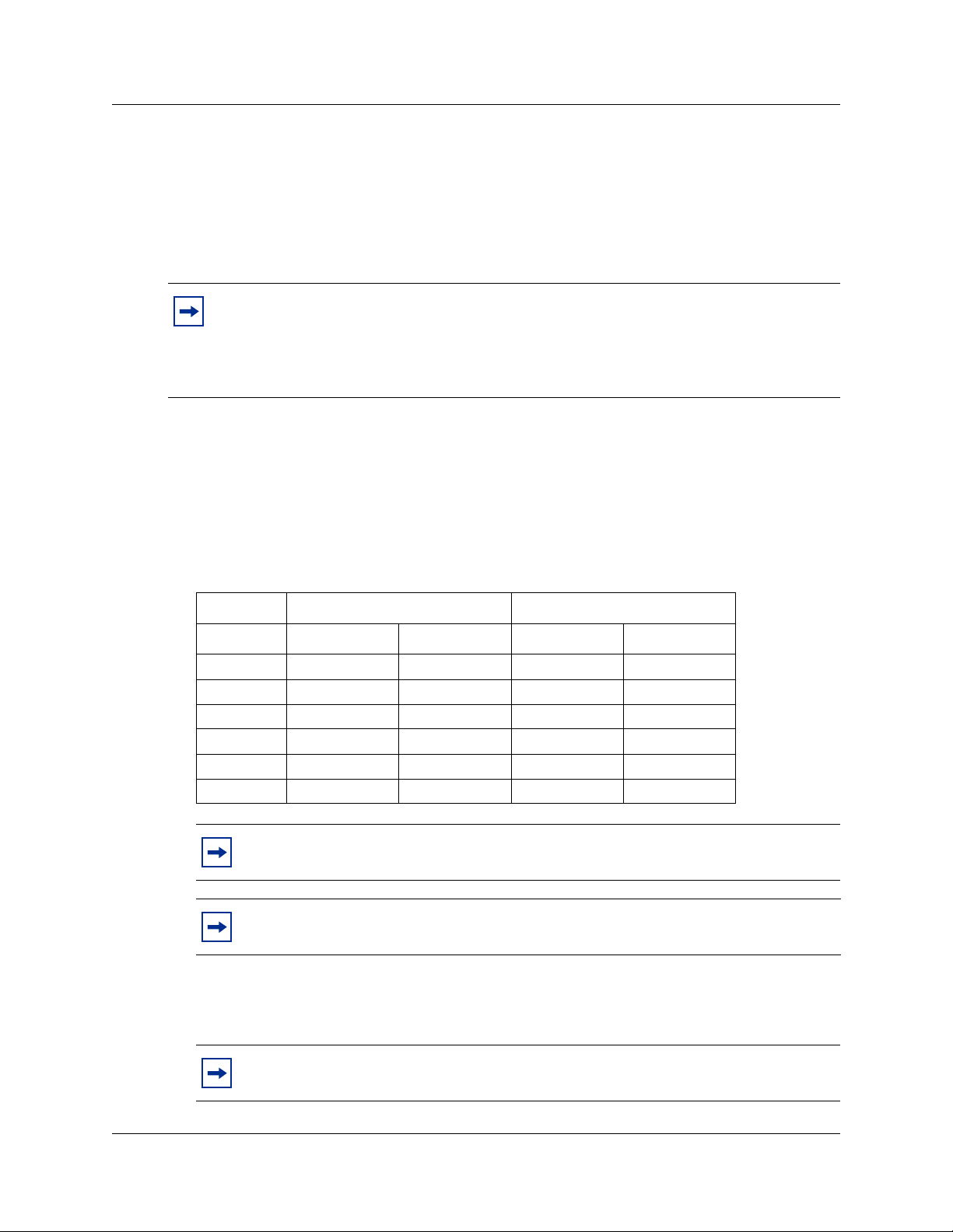
CallPilot features
About CallPilot 100/150 3
Table 1 CallPilot features
Feature CallPilot 100 CallPilot 150
Number of voice channels 4 8
Storage (hours) 9 82
Number of subscriber mailboxes Default: 10
Maximum: 40
Basic voicemail Included Included
Outbound transfer Included Included
Call recording, call interrupt Included Included
Auto-Attendant and Custom Call Routing (CCR) Included Included
Networking (digital, AMIS) Optional Optional
Desktop (Unified) Messaging Optional, depending on
your region
Basic Call Center Optional, depending on
your region
Call Center Reporting Optional Optional
Default: 20
Maximum: 300
Optional, depending on
your region
Optional, depending on
your region
Note: If you are using the Auto-Attendant, only 200 mailboxes are supported.
CallPilot 100/150 Quick Start Guide
Page 4
4 Installing the CallPilot 100/150
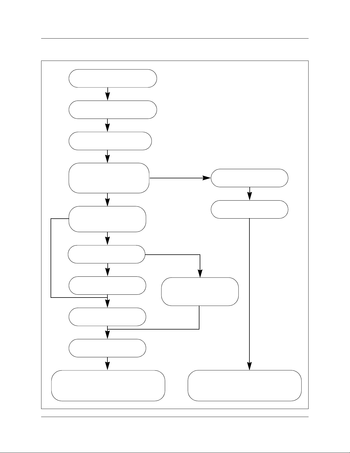
Installing the CallPilot 100/150
Unpack CallPilot 100/150
Mount the CallPilot 100/150
on the wall
Connect the TCM and
power cables
Yes
Initialize CallPilot 100/150
using CallPilot Manager or
a telephone
CallPilot Manger
Can you use the default
IP address
192.168.110.10
No
Change the IP address
serial or Ethernet cable
Serial
Change the IP address
using the serial port
Connect the CallPilot
100/150 to the LAN
Telephone
Ethernet
Determine the feature
codes
Configure the initial
parameters
Change the IP address
using an Ethernet
crossover cable
Start CallPilot 100/150 Administration
programming. Refer to the CallPilot
Manager Set Up and Operation Guide.
N0008008 02
Run the
Quick Install Wizard
Start CallPilot 100/150 Administration
programming. Refer to the CallPilot
Telephone Administration Guide.
Page 5
Mounting the CallPilot 100/150 on the wall
1 Attach the wall mount bracket to a secure surface by the two inner holes. Use anchors, as
necessary.
2 Slip the slot on the back (near the top) of the CallPilot 100/150 onto the bracket.
3 Secure the CallPilot 100/150 using a screw in the lower screw hole.
Note: If you are upgrading from a previous voice messaging system (for example,
FlashTalk) to CallPilot 100/150, you must remove the existing Feature Codes for the old
voice messaging system before you install the CallPilot 100/150. For information about
how to remove the existing Feature Codes, refer to CallPilot 150 Feature Codes are
inactive, in the CallPilot 100/150 Installation and Maintenance Guide.
Connecting the CallPilot 100/150
1 Open the CallPilot 100/150 by inserting a flat screwdriver into the slot on the right-hand side
of the door and pressing the tab out of the way.
Installing the CallPilot 100/150 5
2 Connect a TCM cable to Port A and to Port B.
Table 2 shows the pin out of Port A and Port B.
Table 2 Port A and Port B Pinouts
CallPilot 100 CallPilot 150
Pin number Port A Port B Port A Port B
1 no connection no connection no connection no connection
2 no connection no connection TCM 3 TCM 4
3 TCM 1 TCM 2 TCM 1 TCM 2
4 TCM 1 TCM 2 TCM 1 TCM 2
5 no connection no connection TCM 3 TCM 4
6 no connection no connection no connection no connection
Note: On the CallPilot 100, only TCM 1 and TCM 2 are available for use.
Note: It is very important that you ensure that the Feature Cartridge is inserted into
the bottom PCMCIA slot before you power up the CallPilot unit.
3 Insert the feature cartridge into the bottom PCMCIA slot of the CallPilot 100/150.
4 Connect the other end of the TCM cables to station ports on your Norstar KSU.
Note: Do not connect the Ethernet cable for your LAN to the Ethernet port until you
initialize the CallPilot 100/150.
CallPilot 100/150 Quick Start Guide
Page 6

6 Initializing the CallPilot 100/150
5 Connect the power cable to the CallPilot 100/150 and the wall socket.
6 Run all the cables through the cable trough at the top of the CallPilot 100/150.
7 Close the lid.
Initializing the CallPilot 100/150
Initializing the CallPilot 100/150 sets the system parameters to their default settings and sets some
global parameters. When the initialization is completed, the CallPilot 100/150 is operational and
ready for you to begin administration programming. You can initialize CallPilot 100/150 using
CallPilot Manager or a telephone.
Initializing CallPilot 100/150 using CallPilot Manager
Whenever possible, use CallPilot Manager to initialize CallPilot 100/150. CallPilot Manager
provides access to administration programming not available from a telephone.
To use CallPilot Manager, you must have a network connection to the CallPilot 100/150 or an
Ethernet crossover cable. If you do not have a network connection or an Ethernet crossover cable,
you can initialize the CallPilot 100/150 using a two-line display telephone.
To initialize CallPilot 100/150 using CallPilot Manager you need to:
• determine if your computer meets the CallPilot Manager requirements
• connect to the CallPilot 100/150
• run the Quick Install Wizard
Computer requirements for CallPilot Manager
You access CallPilot Manager using a web browser on a computer that is connected to the
CallPilot 100/150.
• The computer you use to access CallPilot Manager must be compatible with Microsoft
Windows
• To use CallPilot Manager, you must have one of the following browsers:
— Netscape Communicator
— Microsoft Internet Explorer
®
and capable of running your web browser.
1
4.5 or later
2
4.0 or later
Note: CallPilot Manager does not support Netscape 6.0.
®
1 Netscape is a registered trademark and Communicator is a trademark of Netscape Communications
Corporation.
2 Microsoft and Windows are registered trademarks and Internet Explorer is a trademark of Microsoft
Corporation.
N0008008 02
Page 7

Connecting to the CallPilot 100/150
To connect to the CallPilot 100/150, you need the IP address of the CallPilot 100/150 and a
connection to the network that the CallPilot 100/150 is on.
The default IP address for CallPilot 100/150 is 192.168.110.10.
If you can use the default IP address
If the default IP address is compatible with your network, connect the LAN cable to the Ethernet
port on the CallPilot 100/150 and proceed to “Running the Quick Install Wizard” on page 9.
If you cannot use the default IP address
If the default IP address is not compatible, you must change the IP address before you connect the
CallPilot 100/150 to the network. You can change the IP address using a serial cable or an Ethernet
crossover cable (direct PC connection).
Note: If you are unsure if the default IP address is compatible, contact your network
administrator.
Initializing the CallPilot 100/150 7
Changing the IP address using a serial cable
If you are going to change the IP address using a serial cable, you need a:
• serial cable
• VT100-compatible terminal or a computer that has a VT100 compatible terminal emulation
program such as HyperTerminal
Note: The serial port is intended for temporary connections only. After you have finished
changing the IP address, remove the serial cable and close the CallPilot 100/150 door.
Failure to remove the serial cable may result in a non-compliant EMC configuration.
Configuring the terminal
The terminal or terminal emulation program you use must be VT100 compatible and must support
the ASCII Character set. If the terminal does not support the ASCII Character set, the text displays
incorrectly.
You must configure your terminal to the following communications parameters:
• 9600 bits per second
• 8 data bits
• no parity
•1 stop bit
• no flow control
CallPilot 100/150 Quick Start Guide
Page 8

8 Initializing the CallPilot 100/150
For information about how to set these parameters, refer to the documentation for your terminal or
terminal emulation program.
Changing the IP address using the terminal
1 Attach the serial cable to the serial port on the CallPilot 100/150.
2 Attach the other end of the cable to the serial port on the terminal or computer.
3 Ensure that your terminal or computer is powered up.
4 If you are using a computer, start your terminal emulation program.
5 Remove power from the CallPilot 100/150.
Note: Steps 5 and 6 are used to force the CallPilot 100/150 to reboot. You can change
the IP address only while the CallPilot 100/150 is booting up.
6 Reconnect power to the CallPilot 100/150.
The prompt
To change any of this, press any key within 5 seconds appears.
Note: It will take approximately one minute for this prompt to appear.
7 Press the Enter key.
The prompt
(M)odify any of this or (C)ontinue? appears.
Note: If you do not press a key within 5 seconds of this prompt appearing, repeat
steps 5 and 6.
8 Press the M key and press the Enter key.
The prompt
Do you want a LAN interface? appears.
9 Press the Y key and press the Enter key.
The prompt
This board’s LAN IP Address (0.0.0.0 = RARP) appears.
10 Type the IP address for the CallPilot 100/150 in a valid dotted format and press the Enter key.
The prompt
Subnet mask for LAN (0 for none) appears.
11 Type the Subnet Mask for the CallPilot 100/150 in a valid dotted format and press the Enter
key.
The prompt
Should there be a default gateway for packet routing? appears.
12 If the CallPilot 100/150 needs a next hop router, press the Y key and press the Enter key.
If the CallPilot 100/150 does not need a next hop router, press the N key, press the Enter key
and go to step 15.
The prompt
IP address of default gateway? appears.
13 Type the IP address of the next hop router in a valid dotted format and press the Enter key.
14 Press the Enter key until the following prompt appears:
15 Press the C key and press the Enter key.
N0008008 02
(M)odify any of this or (C)ontinue?
Page 9

Initializing the CallPilot 100/150 9
16 Connect the LAN cable to the Ethernet port on the CallPilot 100/150.
You can now initialize the CallPilot parameters. For information about how to initialize the
CallPilot, refer to “Running the Quick Install Wizard” on page 9.
Changing the IP address using an Ethernet crossover cable
Using an Ethernet crossover cable, you can connect the CallPilot 100/150 to your computer. With
this connection, you can use CallPilot Manager to change the CallPilot 100/150 IP address before
you connect it to the network.
Note: If you do not have access to the CallPilot 100/150 through the network, you can use
an Ethernet crossover cable to configure all of the CallPilot 100/150 parameters.
To use an Ethernet crossover cable, your computer must be equipped with a 10/100 BaseT
Ethernet card and support TCP/IP protocol.
Connecting the Ethernet crossover cable
1 Shut down the computer.
2 Attach one end of the Ethernet crossover cable to the Ethernet port on the CallPilot 100/150.
3 Connect the other end of the cable to the network interface card on your computer.
4 Start the computer.
5 Use the Quick Install Wizard to initialize the CallPilot 100/150.
For information about how to use the Quick Install Wizard, refer to “Running the Quick Install
Wizard” on page 9.
Running the Quick Install Wizard
The Quick Install Wizard appears the first time you startup CallPilot Manager. The Quick Install
Wizard is a single page that gathers enough information to set up a working system. It then applies
the information and restarts the system.
You can reach CallPilot Manager from another computer through a LAN connection, WAN/
Internet connection or an Ethernet crossover cable. All of these methods create an IP connection
that allows you to run CallPilot Manager.
Use the following procedure to run the Quick Install Wizard:
1 Launch your browser.
CallPilot 100/150 Quick Start Guide
Page 10

10 Initializing the CallPilot 100/150
2 In the URL address box, type the CallPilot 100/150 IP address.
For example: HTTP://192.168.110.10
Note: You must include HTTP:// to access CallPilot Manager.
The Quick Install Wizard screen appears. Depending on your system, this can take several
minutes.
3 Configure the Quick Install parameters for a CallPilot 100/150 according to following table.
Table 3 Quick Install Wizard parameters for a CallPilot 100/150
Field name Description
IP Address Enter the IP Address or Fully Qualified Domain Name (FQDN) for the CallPilot 100/150. If you do
not know the IP Address or FQDN, contact your network administrator.
This is the IP Address FQDN you will use to access the CallPilot 100/150 using CallPilot
Manager.
Changes to the IP Address take effect when you reboot the CallPilot 100/150.
If this is a re-install, the IP Address shows the current settings, not the factory default.
Warning: If you enter an FQDN in the IP Address box, you must ensure that the
FQDN for the CallPilot 100/150 is in the same subnet as is specified by the Subnet Mask
and the Default Gateway IP address. If you enter an FQDN that is not in the same
subnet, you may cause the CallPilot 100/150 to continuously reboot. To correct this
problem, use the serial interface to change the IP address of the CallPilot 100/150. For
more information, refer to “Changing the IP address using a serial cable” on page 7.
Subnet Mask Enter the Subnet Mask for the CallPilot 100/150. If you do not know the Subnet Mask, contact
Primary DNS Enter the IP Address of the Primary DNS server that CallPilot 100/150 uses. If you do not know
Secondary DNS Enter the IP Address of the Secondary DNS server that CallPilot 100/150 uses. If you do not
Default Gateway Enter the IP Address of the default next-hop router. If you do not know the IP Address, contact
Attendant DN Enter the extension number of the CallPilot attendant.
your network administrator.
Changes to the Subnet Mask take effect when you reboot the CallPilot 100/150.
If this is a re-install, the Subnet Mask shows the current settings, not the factory default.
the IP Address, contact your network administrator.
The Primary DNS server allows you to use domain names, such as www.nortelnetworks.com,
instead of IP addresses when accessing a site.
Note: If you do not use DNS, leave this box blank. CallPilot applications, such as Digital
Networking, can use a DNS server even if you leave this box blank.
know the IP Address, contact your network administrator.
CallPilot 100/150 uses the Secondary DNS server if it cannot contact the Primary DNS server or
if the domain name is not listed in the Primary DNS server.
Note: If you do not use DNS, leave this box blank. CallPilot applications, such as Digital
Networking, can use a DNS server even if you leave this box blank.
your network administrator.
Note: If you do not require a next-hop router, leave this box blank.
N0008008 02
Page 11

Initializing the CallPilot 100/150 11
Table 3 Quick Install Wizard parameters for a CallPilot 100/150
Field name Description
Primary UI Style Select the user interface style assigned to the mailboxes. You can select NVM or CallPilot.
If you select NVM, the mailbox user interface operates like Norstar Voice Mail and FlashTalk.
Users will hear Norstar Voice Mail voice prompts and see Norstar Voice Mail text prompts.
If you select CallPilot, the mailbox user interface operates like Meridian 1 CallPilot. Users will
hear CallPilot voice prompts and see text prompts for CallPilot.
You can change the UI style of individual mailboxes by assigning a different Class of Service to
those mailboxes.
Primary
Language
Country Select the country in which the CallPilot 100/150 is installed.
From Line Enter the line number of the first line in a range of lines that you want the auto-attendant to
To Line Enter the line number of the last line in a range of lines you want the auto-attendant to answer.
Number of rings Enter the number of rings that CallPilot waits before answering a line.
Mailbox Keycode If you have purchased additional mailboxes for CallPilot, enter the keycode you received with
From Extension Enter the extension number of the first telephone in a range of telephones you want to create a
To Extension Enter the extension number of the last telephone in a range of telephones you want to create a
Select the default language that is used for voice prompts, text messages, the Auto-Attendant
and Feature 983 administration.
You can change the language of individual mailboxes by assigning a different Class of Service to
those mailboxes.
The country you select determines several country specific settings such as the telephone
number length, mailbox login sequence and Call Progress Tone Detection. You must select the
country that the CallPilot 100/150 is in to ensure proper operation.
The default is North America.
answer.
The auto-attendant answers this line and all of the lines up to the line number you enter in the To
Line box.
The line number you enter in this box must be the same or higher than the line number you enter
in the From Line box.
your mailbox package.
If you have not purchased additional mailboxes, leave these boxes empty.
Use these boxes only for the keycode for additional mailboxes. Do not enter the keycode that
enables the basic voicemail application.
mailbox for.
A mailbox is created for this telephone and for all of the telephones up to the extension number
you enter in the To Extension box.
The mailboxes are named according the set name of the telephone and assigned Class of
Service 1.
mailbox for.
The extension number you enter in this box must be the same or higher than the extension
number you enter in the From Extension box.
CallPilot 100/150 Quick Start Guide
Page 12

12 Initializing CallPilot 100/150 using a telephone
Table 3 Quick Install Wizard parameters for a CallPilot 100/150
Field name Description
Outdial Method Select the outdial method you want to assign to the mailboxes created using the From Extension
and To Extension boxes. You can choose None, Line, Pool or Route.
If you select None, no outdial method is assigned to the mailboxes.
If you select Line, click the Outdial Method text box and enter the line number of the line you want
assign to the mailboxes.
If you select Pool, click the Outdial Method text box and enter the line pool number of the line
pool you want to assign to the mailboxes.
Note: Line pool numbers 0 to 15 correspond to the Line Pools A to O on the KSU programming
interface.
If you select Route, click the Outdial Method text box and enter the route number of the route you
want to assign to the mailboxes.
4 Click the Install button.
You can now start programming the CallPilot parameters. For information about how to program
CallPilot, refer to the CallPilot Manager Set Up and Operation Guide.
Note: If you have changed any of the IP addresses or the Subnet Mask, you must reboot
the CallPilot 100/150 before you start programming the CallPilot 100/150 parameters.
Initializing CallPilot 100/150 using a telephone
To initialize CallPilot 100/150 you need to:
• determine the CallPilot 100/150 Feature Codes
• configure the CallPilot 100/150 initial parameters
N0008008 02
Page 13

Initializing CallPilot 100/150 using a telephone 13
Determining CallPilot 100/150 Feature Codes
Default Feature Codes are assigned to CallPilot 100/150 by the Norstar system. These default
codes are listed in Table 4. When these default Feature Codes are used by other Norstar
applications, the Norstar system assigns Feature Codes between 900 and 999 to CallPilot 100/150.
These codes might not be assigned in sequential order. Record the assigned Feature Codes in Table
4.
Table 4 Assigned Feature Codes
Feature Code name Default Number
Agent Login
Not Ready
Display Waiting Calls
Leave Message
Open Mailbox
Operator/Service Control
System Administration
Call Forward to Voicemail
CallPilot DN
Transfer to Voicemail
Interrupt
Name Dial
Record Call
≤·‚› ≤· _____ _____
≤·‚° ≤· _____ _____
≤·‚· ≤· _____ _____
≤·°‚ ≤· _____ _____
≤·°⁄ ≤· _____ _____
≤·°¤ ≤· _____ _____
≤·°‹ ≤· _____ _____
≤·°› ≤· _____ _____
≤·°fi ≤· _____ _____
≤·°fl ≤· _____ _____
≤·°‡ ≤· _____ _____
≤·°° ≤· _____ _____
≤·°· ≤· _____ _____
Used By
Call Center only
Call Center only
Call Center only
Call Center and Voicemail
Call Center and Voicemail
Call Center and Voicemail
Call Center and Voicemail
Call Center and Voicemail
Call Center and Voicemail
Call Center and Voicemail
Call Center and Voicemail
Call Center and Voicemail
Call Center and Voicemail
Follow this procedure to determine CallPilot Feature Codes:
1 Press ≤·•⁄ on a two-line display telephone.
2 Record the Feature Code for the first feature used by CallPilot in Table 4.
3 Press NEXT
to show the next Feature Code used by CallPilot. Record this code in Table 4.
4 Repeat step 3 until you reach the final Feature Code.
5 Press QUIT
to end this session.
CallPilot 100/150 Quick Start Guide
Page 14

14 Initializing CallPilot 100/150 using a telephone
Configuring the CallPilot 100/150 initial parameters
To configure the CallPilot 100/150 initial parameters:
1. Press ≤·°‹.
This is the default System Administration feature code. If your
system does not use the default feature codes, enter the System
Administration feature code you determined earlier.
Pswd:
RETRY OK
Bilingual?
YES NO
Primary lang?
ENG FRE
Group lists? Y
CHNG NEXT
Leading digit: 9
CHNG NEXT
2. Enter ¤flfl‹›› (CONFIG) and press OK.
3. Press Y
if you want the display and voice prompts to be available in
two languages.
Press N
if you want the display and voice prompts to be available in
one language.
When you choose N (No) for the Bilingual option, step 6 is not
required and the system automatically goes to step 7.
4. Press the button for the language you want as the Primary
Language.
5. Press CHNG
6. Press NEXT
to toggle the settings between Y for Yes, or N for No.
.
When you choose N (No) for the enable Group List option, steps 9
and 10 are not required and the system automatically goes to step
11.
7. Press CHNG
to enter a new Group List leading digit.
The Group List leading digit can be any number from 0 to 9. Special
Mailbox numbers automatically begin with 1, so if you select a Group
List leading digit of 1, the Special Mailboxes will begin with 2. The
Group List Leading Digit cannot be the same as the first number of
any mailbox.
CallPilot UI:Y
CHNG NEXT
N0008008 02
8. Press NEXT
9. Press CHNG
10. Press NEXT
.
to toggle the settings between Y for Yes, or N for No.
.
Page 15

Configuring the CallPilot 100/150 15
Primary UI:NVM
CHNG NEXT
11. Press CHNG
to toggle the setting between NVM and CP.
If you choose NVM, the mailbox users will see and hear Norstar
Voice Mail prompts when they use their mailboxes.
If you choose CP, the mailbox users will see and hear CallPilot
prompts when they use their mailboxes.
.
.
System config
RETRY OK
Configuring...
System ready
12. Press NEXT
13. Press OK
This message appears on the display.
Initialization takes about three seconds. When complete, the display
shows: System ready and Exit.
Exit
After the initialization programming is completed, the display
automatically returns to the time and date.
Configuring the CallPilot 100/150
After you have initialized the CallPilot 100/150, you can begin configuring the CallPilot features.
For information about how to configure the CallPilot 100/150, refer to the CallPilot Manager Set
Up and Operation Guide or the CallPilot 100/150 Telephone Administration Guide.
Additional information
For more information about installing the CallPilot 100/150 (such as troubleshooting) or how to
install two CallPilot 150 units on one KSU, refer to the CallPilot 100/150 Installation and
Maintenance Guide.
CallPilot 100/150 Quick Start Guide
Page 16

16 Additional information
N0008008 02
 Loading...