

Page 1

Software Release V3.0.0
Part No. 309985-B Rev 00
June 2000
4401 Great America Parkway
Santa Clara, CA 95054
Using the BayStack 410-24T 10BASE-T Switch
Page 2

Copyright © 2000 Nortel Networks
All rights reserved. Pr inted in the USA. Ju ne 2000.
The information in this document is subject to change without notice. The statements, configurations, technical data,
and recommendations in this document are believed to be accurate and reliable, but are presented without express or
implied warranty. Users must take full re sponsib ility for th e ir app lica tio ns o f any products specified in this d ocument.
The information in this document is proprietary to Nortel Networks NA Inc.
Trademarks
NORTEL NETWORKS is a trademark of Nortel Networks Corporation.
Bay Networks and Optivity are registered trademarks and Accelar, BayStack, EZ LAN, Optivity Campus, Optivity
Enterprise, StackProbe, and the Bay Networks logo are trademarks of Nortel Networks NA Inc.
Microsoft, MS, MS -DOS, Win32, Windows, and Windows NT are registered trademarks of Microsoft C orporation.
All other trademarks and registered trademarks are the property of their respective owners.
Statement of Conditions
In the interest of improvi ng internal design, operational function, and/o r relia bi lity, Nortel Network s NA Inc. reserves
the right to make changes to the products described in this document without notice.
Nortel Networks NA Inc. does not assume any liability that may occur due to the use or application of the product(s)
or circuit layout(s) described herein.
USA Requirements Only
Federal Communications Commission (FCC) Compliance Notice: Radio Frequency Notice
Note: This equipment has been tested and found to comply with the limits for a Class A digital device, pursuant to
Part 15 of the FCC rules. These limits are designed to provide reaso nable protection against harmful interferenc e
when the equipment is operat ed in a commercial environment. This equipment generates, uses, and can radiate radio
frequency energy. If it is not installed and used in accordance with the instruction manual, it may cause harmful
interference to radio communications. Operation of this equipment in a residential area is likely to cause harmful
interference, in which case users will be required to take whatever measures may be necessary to correct the
interference at their own expense.
European Requirements Onl y
EN 55 022 Statement
This is to certify that the Nortel Networks BayStack 410-24T switch is shielded against the generation of radio
interference in accordance with the application of Council Directive 89/336/EEC, Article 4a. Conform ity is declared
by the application of E N 55 022 Class A (CISPR 22) .
Warning: This is a Class A product. In a domestic environment, this produc t may cau se radio in terf eren ce, in whic h
case, the user may be required to take appropriate measures.
Achtung: Dieses ist ein Gerät der Funkstörgrenzwertklasse A. In Wohnbereichen können bei Betrieb dieses Gerätes
Rundfunkstörungen auftreten, in welchen Fällen der Benutzer für entsprechende Gegenmaßnahmen verantwortlich
ist.
Attention: Ceci est un produi t de Classe A. Dans un environnement domestique, ce produ it risque de créer des
interférences radioélectriques, il appartiendra alors à l’utilisateur de prendre les mesures spécifiques appropriées.
ii
309985-B Rev 00
Page 3

EC Declaration of Conformity
This product conf orms (or these products conform) to the provisions of Council D irective 89/336/EEC and
73/23/EEC. The Declaration of Confor mity is available on the Nortel Networks World Wide Web site at
http://libra2.corpwest.baynetworks.com/cgi-bin/ndCGI.exe/DocView/.
Japan/Nippon Requirements Only
Voluntary Control Council for Interference (VCCI) Statement
Voluntary Control Council for Interference (VCCI) Statement
This is a Class A product based on the standard of the Voluntary Control Council for Interference by Information
Technology Equipment (VCCI). If this equipment is used in a domestic environment, radio disturbance may arise.
When such trouble occurs, the user may be required to take corrective actions.
Taiwan Requirements
Bureau of Standards, Metrology and Inspection (BSMI) Statement
Canada Requirements Only
Canadian Department of Communications Radio Interference Regulations
This digital apparatus (BayStack 410-24T switch) does not exceed the Class A limits for radio-noise emissions from
digital apparatus as set out in the Radio Interference Regulations of the Canadian Department of Communications.
Règlement sur le brouillage radioélectrique du ministère des Communications
Cet appareil numérique (BayStack 410-24T switch) respecte les limites de bruits radioélectriques visant les appareils
numériques de classe A prescrites dans le Règlement sur le brouillage radioélectrique du ministère des
Communications du Canada.
309985-B Rev 00
iii
Page 4

Nortel Networks NA Inc. Software License Agreement
NOTICE: Please carefully read this license agreement before copying or using the accompanying software or
installing the hardware unit with pre-enabled software (each of which is referred to as “Software” in this Agreement).
BY COPYING OR USING THE SOFTWARE, YOU ACCEPT ALL OF THE TERMS AND CONDITIONS OF
THIS LICENSE AGREEMENT. THE TERMS EXPRESSED IN THIS AGREEMENT ARE THE ONLY TERMS
UNDER WHICH NORTEL NETWORKS WILL PERMIT YOU TO USE THE SOFTWARE. If you do not accept
these terms and conditions, return the product, unused and in the original shipping container, within 30 days of
purchase to obtain a credit for the full purchase price.
1. License Grant. Nortel Networks NA Inc. (“Nortel Networks”) grants the end user of the Software (“Licensee”) a
personal, nonexc lusi v e, no ntransferab le licen se: a) to u se the So ftw are eithe r on a sing le compu ter or, if applicable, on
a single authorized device identified by host ID, for which it was originally acquired; b) to copy the Software solely
for backup purposes i n support of authorized use of the Software; and c) to use and copy the associated user manual
solely in support of authorized use of the Software by Licensee. This license applies to the Software only and does not
extend to Nortel Networks Agent software or other Nortel Networks software products. Nortel Networks Agent
software or other Nortel Networks software products are licensed for use under the terms of the applicable Nortel
Networks NA Inc. Software License Agreement that accompanies such software and upon payment by the end user of
the applicable license fees for such soft ware .
2. Restrictions on use; reservation of rights. The Software and user manuals are protected under copyright laws.
Nortel Networks and/or its licensors retain all title and ownership in both the Software and user manuals, including
any revisions made by Nortel Networks or its li censors. The copyright not ice must be reproduce d and included with
any copy of any portion of the Software or user manuals. Licensee may not modify, translate, decompile, disassemble,
use for any competitive analysis, reverse engineer, distribute, or create derivative works from the Software or user
manuals or any copy , in whole or in part. Except as expressly provided in this Agreement, Licensee may not copy or
transfer the Software or user manuals, in whole or in part. The Software and user manuals embody Nortel Networks’
and its licensors’ confidential and pro pri etary inte lle ctu al pro p erty. Licensee shall n ot sub lice nse, assign, or otherwise
disclose to any third party the Software, or any information about the operation, design, performance, or
implementation of the Software and user manuals that is confidential to Nortel Networks and its licensors; however,
Licensee may grant permission to its consultants, subcontractors, and agents to use the Software at Licensee’s facility ,
provided they have agreed to use the Software only in accordance with the terms of this license.
3. Limited warranty . Nortel Networks warrants each item of Software, as delivered by Nortel Networks and properly
installed and operated on Nortel Networks hardware or other equipment it is originally licensed for, to function
substantially as described in its accompanying user manual during its warranty period, which begins on the date
Software is first shipped to Licensee. If an y item of Softwa re fails to so f unction during its wa rranty period, as the sole
remedy Nortel Networks will at its discretion provide a suitable fix, patch, or workaround for the problem that may be
included in a future Software release. Nortel Networks further warrants to Licensee that the media on which the
Software is provided will be free from defec ts in materials and wo rkmanship under normal u se for a period of 90 days
from the date Software is first shipped to Licensee. Nortel Networks will replace defective media at no charge if it is
returned to Nortel Net w orks during the warran ty period along with proof of the date of shipment. This warranty does
not apply if the media has been damaged as a result of accident, misuse, or abuse. The Licensee assumes all
responsibility for selection of the Softw are to achieve Licensee’s intended results and for the installation, use, and
results obtained from the Software. Nortel Networks does not warrant a) that the functions contained in the software
will meet the Licensee’s requirements, b) that the Softw are will operate in the hardw are or software combina tions that
the Licensee may select, c) that the operation of the Software will be uninterrupted or error free, or d) that all defects
in the operation of the Softw are will be correcte d. Nortel Netw orks is not oblig ated to remedy any Sof tware defect that
cannot be reproduced with the latest Software release. These warranties do not apply to the Software if it has been (i)
altered, except by Nortel Networks or in accordance with its instruct ions; (ii) used in conjunction with an ot her
vendor’s product, resultin g in the defect; or (iii) damaged by improper environment, abuse, mi suse, accident, or
negligence. THE FOREGOING WARRANTIES AND LIMITATIONS ARE EXCLUSIVE REMEDIES AND ARE
IN LIEU OF ALL OTHER WA RRANTIES EXPRESS OR IMPLIED, INCLUDING WITHOUT LIMITATION ANY
WARRANTY OF MERCHANTABILITY OR FITNESS FOR A PARTICULAR PURPOSE.
iv
309985-B Rev 00
Page 5

Licensee is responsible for the secu rity of its o w n data an d infor mation an d for mainta ining adequate procedure s apart
from the Software to reconstruct lost or altered files, data, or programs.
4. Limitation of liability. IN NO EVENT WILL NORTEL NETWORKS OR ITS LICENSORS BE LIABLE FOR
ANY COST OF SUBSTITUTE PROCUREMENT; SPECIAL, INDIRECT, INCIDENTAL, OR CONSEQUENTIAL
DAMAGES; OR ANY DAMAGES RESULTING FROM INACCURATE OR LOST DATA OR LOSS OF USE OR
PROFITS ARISING OUT OF OR IN CONNECTION WITH THE PERFORMANCE OF THE SOFTWARE, EVEN
IF NORTEL NETWORKS HAS BEEN ADVISED OF THE POSSIBILITY OF SUCH DAMAGES. IN NO EVENT
SHALL THE LIABILITY OF NORTEL NETWORKS RELATING TO THE SOFTWARE OR THIS AGREEMENT
EXCEED THE PRICE PAID TO NORTEL NETWORKS FOR THE SOFTWARE LICENSE.
5. Government Licensees. This provision applies to all S oftware a nd document ation acqu ired directly or indirect ly by
or on behalf of the United States Government. The Software and documentation are commercial products, licensed on
the open market at market prices, and were developed entirely at private expense and without th e use of any U.S.
Government funds. The license to the U.S. Government is granted only with restricted rights, and use, duplication, or
disclosure by the U.S. Government is subject to the restrictions set forth in subparagraph (c)(1) of the Commercial
Computer Software––Restricted Rights clause of FAR 52.227-19 and th e lim itatio ns se t o ut in thi s licen se for civilian
agencies, and subparagraph (c)(1)(ii ) of the Rights in Technical Data and Computer Software clause of DFARS
252.227-7013, for agencies of the Department of Defense or their successors, whi chever is applicable.
6. Use of Software in the European Community. This provision applies to all Software acquired for use within the
European Community. If Licensee uses the Software within a country in the European Community, the Software
Directive enacted by the Council of European Communities Directive dated 14 May, 1991, will apply to the
examination of the Software to facilitate interoperability. Licensee agrees to notify Nortel Networks of any such
intended examination of the Software and may procure support and assistance from Nortel Net wor ks.
7. Term and termination. This license is effective until terminated; ho wever, all of the restrictions with respect to
Nortel Networks’ copyright in the Software and user manuals will cease being effective at the date of expiration of the
Nortel Networks copyright; t hose restrictions relating to use and disclosur e of Nortel Networks’ confidential
information shall continue in effect. Licensee may terminate this license at any time. The license will automatically
terminate if Licensee fails to comply with any of the terms and conditions of the license. Upon termination for any
reason, Licensee will immediately destroy or return to Nortel Networks the Software, user manuals, and all copies.
Nortel Networks is not liable to Licensee for damages in any form solely by reason of the termination of this license.
8. Export and Re-export. Licensee agrees not to export, directly or indirectly, the Software or related technical data
or information without first obtaining any required export licenses or other governmental approvals. Without limiting
the foregoing, Licensee, on behalf of itself and its subsidiaries and affiliates, agrees that it will not, without first
obtaining all export licenses and approvals required by the U.S. Government: (i) export, re-export, transfer, or divert
any such Software or technical data, or any direc t product thereof, to any country to which such export s or re-exports
are restricted or em bargoed under United State s e x port control laws and regu la tions, or to any national or resident of
such restricted or embargoed countries; or (ii) provide the Software or related technical data or information to any
military end user or for any military end use, including the design, development, or production of any chemical,
nuclear, or biological weapons.
9. General. If any provision of this Agreement is held to be invalid or unenforceable by a court of competen t
jurisdiction, the remainder of the provisions of this Agreement shall remain in full force and effect. This Agreement
will be governed by the laws of the state of California.
Should you have any questions concerning this Agreement, contact Nortel Networks, 4401 Great America Parkway,
P.O. Box 58185, Santa Clara, California 95054-8185.
LICENSEE ACKNOWLEDGES THAT LICENSEE HAS READ THIS AGREEMENT, UNDERSTANDS IT, AND
AGREES TO BE BOUND BY ITS TERMS AND CONDITIONS. LICENSEE FURTHER AGREES THAT THIS
AGREEMENT IS THE ENTIRE AND EXCLUSIVE AGREEMENT BETWEEN NORTEL NETWORKS AND
LICENSEE, WHICH SUPERSEDES ALL PRIOR ORAL AND WRITTEN AGREEMENTS AND
COMMUNICATIONS BETWEEN THE PARTIES PERTAINING TO THE SUBJECT MATTER OF THIS
AGREEMENT. NO DIFFERENT OR ADDITIONAL TERMS WILL BE ENFORCEABLE AGAINST NORTEL
NETWORKS UNLESS NORTEL NETWORKS GIVES ITS EXPRESS WRITTEN CONSENT, INCLUDING AN
EXPRESS WAIVER OF THE TERMS OF THIS AGREEMENT.
309985-B Rev 00
v
Page 6

Page 7

Contents
Preface
Before You Begin ...........................................................................................................xxiv
Organization ..................................................................................................................xxiv
Text Conventions ............................................................................................................xxv
Acronyms ........................... .......................... .......................... ......................... ...............xxvi
Related Publications .....................................................................................................xxvii
How to Get Help .......................................................................................................... xxviii
Chapter 1
Introduction to the BayStack 410-24T Switch
Description ............ ...... ....... ...... ....... ...... ....... ...... ............................................. ....... .........1-1
Front Panel ...............................................................................................................1-2
Comm Port ........................................................................................................1-2
Uplink/Expansion Slot ........................................................................................1-3
10BASE-T Port Connectors ...............................................................................1-3
LED Display Panel .............................................................................................1-4
Back Panel ...............................................................................................................1-6
AC Power Receptacle ........................................................................................1-7
RPSU Connector ...............................................................................................1-8
Cascade Module Slot ........................... ....... ...... ............................................. ...1-8
Cooling Fans ......................................................................................................1-8
Features ......................................... .......................................................................... 1-9
Virtual Local Area Networks (VLANs) ..........................................................................1-12
Security ................. ...... ....... ...... ....... ...... ....... ...... ............................................. ....... .... ...1-13
RADIUS-Based Network Security ..........................................................................1-15
MAC Address-Based Security ................................................................................1-15
IEEE 802.1p .................................................................................................................1-16
309985-B Rev 00
vii
Page 8

IGMP Snooping Feature ...............................................................................................1-16
Configuration and Switch Management ........................................................................1-16
Flash Memory Storage ................................ ...... ....... ...... ....... ...... ...... ....... ....................1-17
Switch Software Image ..........................................................................................1-17
Configuration Parameters ......................................................................................1-17
Autosensing and Autonegotiation .................................................................................1-18
MultiLink Trunking ....... ....... ...... ....... ...... ....... ...... ....... ...... ....... ...... ...... ...........................1-18
IEEE 802.1Q VLANs ....................................................................................................1-19
Port Mirroring ................................................................................................................1-19
BootP Automatic IP Configuration/MAC Address .........................................................1-20
SNMP MIB Suppor t .... ....... ...... ....... ...... ............................................. ...........................1-21
SNMP Trap Support ................. .............................................. .......................................1-2 1
Network Configuration ..................................................................................................1-22
Desktop Switch Application ....................................................................................1-22
Segment Switch Application ...................................................................................1-24
High-Density Switched Workgroup Applicatio n ........................... ....... ...... ....... ...... .1-2 5
Fail-Safe Stack Application .....................................................................................1-26
Stack Operation ............................................................................................................1-27
BayStack 400-ST1 Cascade Module .....................................................................1-27
Cascade A Out Connector ...............................................................................1-28
Unit Select Switch ............................................................................................1-28
Cascade A In Connector .................................................................................1-28
Base Unit ................................................................................................................1-29
Initial Installation ..............................................................................................1-29
Stack MAC Address .........................................................................................1-30
Temporary Base Unit .......................................................................................1-30
Removing a Unit from the Stack ......................................................................1-31
Stack Configurations ..............................................................................................1-31
Stack Up Configurations ..................................................................................1-32
Stack Down Configurations .............................................................................1-32
Redundant Cascade Stacking Feature ..................................................................1-34
viii
309985-B Rev 00
Page 9

IEEE 802.1Q VLAN Workgroups ..................................................................................1-36
IEEE 802.1Q Tagging .............................................................................................1-37
VLANs Spanning Multiple Switches .......................................................................1-41
VLANs Spanning Multiple 802.1Q Tagged Switches .......................................1-41
VLANs Spanning Multiple Untagged Switches ................................................1-42
Shared Servers ......................................................................................................1-44
VLAN Workgroup Summary ...................................................................................1-49
VLAN Configuration Rules .....................................................................................1-51
IGMP Snooping ............................................................................................................1-52
IGMP Snooping Configuration Rules .....................................................................1-56
IEEE 802.1p Prioritizing ...............................................................................................1-57
MultiLink Trunks .............................................................. ....... .......................................1- 61
Client/Server Configuration Using MultiLink Trunks ...............................................1-62
Trunk Configuration Screen Examples ...................................................................1-64
Trunk Configuration Screen for Switch S1 .......................................................1-64
Trunk Configuration Screen for Switch S2 .......................................................1-67
Trunk Configuration Screen for Switch S3 .......................................................1-69
Trunk Configuration Screen for Switch S4 .......................................................1-71
Before Configuring Trunks ......................................................................................1-73
MultiLink Trunking Configuration Rules . ...... ....... ...... ....... .......................................1-73
How the MultiLink Trunk Reacts to Losing Distributed Trunk Members .................1-75
Spanning Tree Considerations for MultiLink Trunks ...............................................1-76
Additional Tips About the MultiLink Trunking Feature ............................................1-79
Port Mirroring (Conversation Steering) .........................................................................1-80
Port-Based Mirroring Configu ration ....................................... .................................1-81
Address-Based Mirroring Configuration .................................................................1-83
Port Mirroring Configuration Rules .........................................................................1-86
Chapter 2
Installing the BayStack 410-24T Switch
Installation Requirements ...............................................................................................2-1
Installation Procedure .....................................................................................................2-3
Installing the BayStack 410-24T Switch on a Flat Surface .......................................2-3
Installing the BayStack 410-24T Switch in a Rack ...................................................2-4
309985-B Rev 00
ix
Page 10

Attaching Devices to the BayStack 410-24T Switch ................................................2-7
Connecting 10BASE-T Ports and 10/100 MDA Ports ........................................2-8
Connecting Fiber Optic MDA Ports ....................................................................2-9
Console/Comm Port ........................................................................................2-10
Connecting a Terminal to the Console/Comm Port ..........................................2-11
Connecting Power .........................................................................................................2-12
Verifying the Installation ................................................................................................2-14
Verifying the Installation Using the LEDs ...............................................................2-14
Verifying the Installation Using the Self-Test Screen ..............................................2-15
Initial Setup ...................................................................................................................2-17
Standalone Switch Setup .......................................................................................2-17
Stack Setup ............................................................................................................2-20
Chapter 3
Using the Console Interface
Accessing the CI Menus and Screens ............................................................................3-1
Using the CI Menus and Screens ...................................................................................3-2
Navigating the CI Menus and Screens .....................................................................3-2
Screen Fields and Descriptions ...............................................................................3-3
Main Menu ......................................................................................................................3-4
IP Configuration/Setup ................................ ............................................. ......................3-8
Choosing a BootP Request Mode ................................................................................3-10
BootP Disabled ......................................................................................................3-11
BootP or Last Address ...........................................................................................3-11
BootP When Needed .............................................................................................3-12
BootP Always .........................................................................................................3-12
SNMP Configuration ................ .............................................. .......................................3-1 3
System Characteristics ...... ...... ....... ...... ....... ...... ....... ............................................. ....... 3 -15
Switch Configuration .....................................................................................................3-18
MAC Address Table ................................................................................................3-20
MAC Address-Based Security ................................................................................3-22
MAC Address Security Configuration ..............................................................3-24
MAC Address Security Port Configuration .......................................................3-28
MAC Address Security Port Lists .....................................................................3-31
MAC Address Security Table ...........................................................................3-35
x
309985-B Rev 00
Page 11

VLAN Configuration Menu .....................................................................................3-38
VLAN Configuration .........................................................................................3-40
VLAN Port Configuration .................................................................................3-46
VLAN Display by Port ......................................................................................3-49
Traffic Class Configuration ...............................................................................3-50
Port Configuration ..................................................................................................3-52
High Speed Flow Control Configuration .................................................................3-54
Choosing a High Speed Flow Control Mode ....................................................3-56
MultiLink Trunk Configuration ................ ...... ....... ....................................................3-57
MultiLink Trunk Configuration Screen ..............................................................3-59
MultiLink Trunk Utilization Screen ................ ...... ....... ...... ...... ....... ...... ....... ....... 3 -61
Port Mirroring Configuration ...................................................................................3-64
Rate Limiting Configuration ....................................................................................3-68
IGMP Configuration Menu ......................................................................................3-71
IGMP Configuration .........................................................................................3-72
Multicast Group Membership ............................. ....... ...... ...... ...........................3-76
Port Statistics .........................................................................................................3-78
Console/Comm Port Configuration ...............................................................................3-82
Renumber Stack Units ..................................................................................................3-89
Hardware Unit Information ............................................................................................3-91
Spanning Tree Configuration ........................................................................................3-91
Spanning Tree Port Configuration ..........................................................................3-93
Display Spanning Tree Switch Settings ..................................................................3-96
TELNET Configuration .................................................................................................3-99
Software Download .....................................................................................................3-102
Configuration File .......................................................................................................3-106
Display Event Log .......................................................................................................3-109
Excessive Bad Entries .........................................................................................3-110
Write Threshold ....................................................................................................3-110
Flash Update .. ...... ....... ...... ....... ...... ....... ...... ....... ...... ....... .....................................3-11 1
Reset ..........................................................................................................................3-112
Reset to Default Settings ............................................................................................3-114
Logout ................................ ................... .................... ................... ................... ............3-117
309985-B Rev 00
xi
Page 12

Chapter 4
Troubleshooting
Interpreting the LEDs .....................................................................................................4-2
Diagnosing and Correcting the Problem ................... ...... ....... ...... ...... ....... ...... ....... .........4-4
Normal Power-Up Sequence ....................................................................................4-5
Port Connection Problems .......................................................................................4-6
Autonegotiation Modes ......................................................................................4-7
Port Interface .....................................................................................................4-7
Software Download Error Codes ....................................................................................4-8
Appendix A
Technical Specifications
Environmental .......................... ................................. ................................ ..................... A-1
Electrical ............... .......................................................... ............................................... A-1
Physical Dimensions ...................................................................................................... A-2
Performance Specifications ........................................................................................... A-2
Network Protocol and Standards Compatibility ............................................................. A-2
Data Rate ......................................................................................................................A-3
Interface Options ........................................................................................................... A-3
Safety Agency Certification ........................................................................................... A-3
Electromagnetic Emissions ........................................................................................... A-3
Electromagnetic Immunity ............................................................................................. A-4
Declaration of Conformity .............................................................................................. A-4
Appendix B
Media Dependent Adapters
10BASE-T/100BASE-TX MDA ...................................................................................... B-2
100BASE-FX MDAs ....................................................................................................... B-3
Installing an MDA ......................................... ...... ....... ...... ....... ...... ...... ....... ...... ....... ...... .. B-6
Replacing an MDA with a Different Model ..................................................................... B-7
Appendix C
Quick Steps to Features
Configuring 802.1Q VLANs ...........................................................................................C-2
Configuring MultiLink Trunks .........................................................................................C-5
Configuring Port Mirroring .............................................................................................C-6
Configuring IGMP Snooping .......................................................................................... C-8
xii
309985-B Rev 00
Page 13

Appendix D
Connectors and Pin Assignments
RJ-45 (10BASE-T/100BASE-TX) Port Connectors ........ ....... ...... ...... ....... ...... ....... ...... .. D-1
MDI and MDI-X Devices ................................................................................................D-2
MDI-X to MDI Cable Connections ........................................................................... D-3
MDI-X to MDI-X Cable Connections ..... ...... ....... ...... ............................................. .. D-4
DB-9 (RS-232-D) Console/Comm Port Connector ... ............................................. ........D-5
Appendix E
Default Settings
Appendix F
Sample BootP Configuration File
Index
309985-B Rev 00
xiii
Page 14

Page 15

Figures
Figure 1-1. BayStack 410-24T Switch ........................................................................1-1
Figure 1-2. BayStack 410-24T Switch Front Panel .....................................................1-2
Figure 1-3. BayStack 410-24T Switch LED Display Panel .........................................1-4
Figure 1-4. BayStack 410-24T Switch Back Panel .....................................................1-6
Figure 1-5. BayStack 410-24T Switch Security Feature ...........................................1-13
Figure 1-6. BayStack 410-24T Switch Used as a Desktop Switch ...........................1-23
Figure 1-7. BayStack 410-24T Switch Used as a workgroup Switch .......................1-24
Figure 1-8. Configuring Power Workgroups and a Shared Media Hub ....................1-25
Figure 1-9. Fail-Safe Stack Example ........................................................................1-26
Figure 1-10. BayStack 400-ST1 Front Panel Components ........................................1-27
Figure 1-11. Connecting Cascade Cables .................................................................1-28
Figure 1-12. Stack Up Configuration Example ...........................................................1-32
Figure 1-13. Stack Down Configuration Example .......................................................1-33
Figure 1-14. Redundant Cascade Stacking Feature ..................................................1-35
Figure 1-15. Port-Based VLAN Example ......... ....... ...... ....... ...... ...... ....... ...... ..............1-36
Figure 1-16. Default VLAN Settings ...........................................................................1-38
Figure 1-17. Port-Based VLAN Assignment ................. ....... ...... .................................1-39
Figure 1-18. 802.1Q Tagging (After Port-Based VLAN Assignment) .........................1-39
Figure 1-19. 802.1Q Tag Assignment .........................................................................1-40
Figure 1-20. 802.1Q Tagging (After 802.1Q Tag Assignment) ...................................1-40
Figure 1-21. VLANs Spanning Multiple 802.1Q Tagged Switches .............................1-41
Figure 1-22. VLANs Spanning Multiple Untagged Switches ......................................1-42
Figure 1-23. Possible Problems with VLANs and Spanning Tree Protocol .................1-43
Figure 1-24. Multiple VLANs Sharing Resources .......................................................1-44
Figure 1-25. VLAN Broadcast Domains Within the Switch .........................................1-45
Figure 1-26. Default VLAN Configuration Screen Example ........................................1-46
Figure 1-27. VLAN Configuration Screen Example ....................................................1-47
Figure 1-28. Default VLAN Port Configuration Screen Example ................................1-48
Figure 1-29. VLAN Port Configuration Screen Example ............................................1-49
309985-B Rev 00
xv
Page 16

Figure 1-30. VLAN Configuration Spanning Multiple Switches ..................................1-50
Figure 1-31. IP Multicast Propagation With IGMP Routing ........................................1-53
Figure 1-32. BayStack 410-24T Switch Filtering IP Multicast Streams (1 of 2) ..........1-54
Figure 1-33. BayStack 410-24T Switch Filtering IP Multicast Streams (2 of 2) ..........1-55
Figure 1-34. Prioritizing Packets ................................................ ...... ....... ...... ....... ...... .1-5 7
Figure 1-35. Port Transmit Queue ..............................................................................1-58
Figure 1-36. Default Traffic Class Configuration Screen Example .............................1-59
Figure 1-37. Setting Port Priority Example .................................................................1-60
Figure 1-38. Switch-to-Switch Trunk Configuration Example .....................................1-61
Figure 1-39. Switch-to-Server Trunk Configuration Example .....................................1-62
Figure 1-40. Client/Server Configuration Example .....................................................1-63
Figure 1-41. Choosing the MultiLink Trunk Configuration Screen ..............................1-64
Figure 1-42. MultiLink Trunk Configuration Screen for Switch S1 ..............................1-65
Figure 1-43. MultiLink Trunk Configuration Screen for Switch S2 ..............................1-67
Figure 1-44. MultiLink Trunk Configuration Screen for Switch S3 ..............................1-69
Figure 1-45. MultiLink Trunk Configuration Screen for Switch S4 ..............................1-71
Figure 1-46. Loss of Distributed Trunk Members .......................................................1-75
Figure 1-47. Path Cost Arbitration Example ...............................................................1-76
Figure 1-48. Example 1: Correctly Configured Trunk .................................................1-77
Figure 1-49. Example 2: Detecting a Misconfigured Port .......... ...... ....... ...... ....... ....... 1 -78
Figure 1-50. Port-Based Mirroring Configu ratio n Exampl e .................... ...... ....... ...... .1-81
Figure 1-51. Port Mirroring Port-Based Screen Example ...........................................1-83
Figure 1-52. Address-Based Mirroring Configuration Example ..................................1-84
Figure 1-53. Port Mirroring Address-Based Screen Example ....................................1-85
Figure 2-1. Package Contents ....................................................................................2-2
Figure 2-2. Positioning the Chassis in the Rack .........................................................2-5
Figure 2-3. Attaching Mounting Brackets ...................................................................2-6
Figure 2-4. Installing the Switch in an Equipment Rack .............................................2-6
Figure 2-5. 10BASE-T Port Connections ...................................................................2-8
Figure 2-6. Fiber Optic Port Connections ...................................................................2-9
Figure 2-7. Connecting to the Console/Comm Port .................................................2-11
Figure 2-8. BayStack 410-24T Switch AC Power Receptacle ..................................2-13
Figure 2-9. Grounded AC Power Outlet ....................................................................2-13
Figure 2-10. Observing LEDs to Verify Proper Operation ..........................................2-14
Figure 2-11. BayStack 410-24T Switch Self-Test Screen ...........................................2-15
xvi
309985-B Rev 00
Page 17

Figure 2-12. Nortel Networks Logo Screen ................................................................2-16
Figure 2-13. Main Menu .............................................................................................2-18
Figure 2-14. IP Configuration/Setup Screen (Standalone Switch) .............................2-19
Figure 2-15. Main Menu (Standalone Switch Example) .............................................2-21
Figure 2-16. Main Menu (Stack Configuration Example) ............................................2-21
Figure 2-17. IP Configuration/Setup Screen (Stack Configuration) ............................2-22
Figure 3-1. Map of Console Interface Screens ...........................................................3-3
Figure 3-2. Console Interface Main Menu ..................................................................3-4
Figure 3-3. IP Configuration/Setup Screen ................................................................3-8
Figure 3-4. SNMP Configuration Screen .............. ...... ....... ...... ...... ...........................3-13
Figure 3-5. System Characteristics Screen ................ ....... .......................................3-1 5
Figure 3-6. Switch Configuration Menu Screen ........................................................3-18
Figure 3-7. MAC Address Table Screen ...................................................................3-21
Figure 3-8. MAC Address Security Configuration Menu ..........................................3-23
Figure 3-9. MAC Address Security Configuration Screen ........................................3-25
Figure 3-10. MAC Address Security Port Configuration (Screen 1 of 2) ....................3-28
Figure 3-11. MAC Address Security Port Configuration (Screen 2 of 2) ....................3-29
Figure 3-12. MAC Address Security Port Lists Screens (5 Screens) .........................3-31
Figure 3-13. MAC Address Security Port Lists Screen ..............................................3-32
Figure 3-14. MAC Address Security Table Screens (16 Screens) ..............................3-35
Figure 3-15. MAC Address Security Table Screen .....................................................3-36
Figure 3-16. VLAN Configuration Menu Screen .........................................................3-39
Figure 3-17. VLAN Configuration Screen ..................... ....... ...... ...... ....... ...... ....... ...... .3-4 1
Figure 3-18. VLAN Port Configuration Screen ...........................................................3-47
Figure 3-19. VLAN Display by Port Screen ................................................................3-49
Figure 3-20. Traffic Class Configuration Screen .........................................................3-51
Figure 3-21. Port Configuration Screen (1 of 2) .........................................................3-52
Figure 3-22. Port Configuration Screen (2 of 2) .........................................................3-53
Figure 3-23. High Speed Flow Control Configuration Screen ....................................3-55
Figure 3-24. MultiLink Trunk Configuration Menu Screen ..........................................3-58
Figure 3-25. MultiLink Trunk Configuration Screen ....................................................3-60
Figure 3-26. MultiLink Trunk Utilization Screen (1 of 2) ....... ...... ...... ....... ....................3-62
Figure 3-27. MultiLink Trunk Utilization Screen (2 of 2) ....... ...... ...... ....... ....................3-63
Figure 3-28. Port Mirroring Configuration Screen ......................................................3-65
Figure 3-29. Rate Limiting Configuration Screen (1 of 2) ...........................................3-68
309985-B Rev 00
xvii
Page 18

Figure 3-30. Rate Limiting Configuration Screen (2 of 2) ...........................................3-69
Figure 3-31. IGMP Configuration Menu Screen .........................................................3-71
Figure 3-32. IGMP Configuration Screen ...................................................................3-73
Figure 3-33. Multicast Group Membership Screen .....................................................3-77
Figure 3-34. Port Statistics Screen .............................................................................3-78
Figure 3-35. Console/Comm Port Configuration Screen ............................................3-82
Figure 3-36. Renumber Stack Units Screen ...............................................................3-89
Figure 3-37. Hardware Unit Information Screen .........................................................3-91
Figure 3-38. Spanning Tree Configuration Menu Screen ...........................................3-92
Figure 3-39. Spanning Tree Port Configuration Screen (1 of 2) .................................3-93
Figure 3-40. Spanning Tree Port Configuration Screen (2 of 2) .................................3-94
Figure 3-41. Spanning Tree Switch Settings Screen ..................................................3-96
Figure 3-42. TELNET Configuration Screen ..............................................................3-99
Figure 3-43. Software Download Screen .................................................................3-103
Figure 3-44. Configuration File Download/Upload Screen .......................................3-106
Figure 3-45. Event Log Screen ................................................................................3-109
Figure 3-46. Sample Event Log Entry Showing Excessive Bad Entries ...................3-110
Figure 3-47. Sample Event Log Entry Exceeding the Write Threshold ....................3-111
Figure 3-48. Sample Event Log Entry Showing Flash Update Status ......................3-111
Figure 3-49. Self-Test Sc reen Aft er Resetting the Switc h ............... ....... ...... ....... .....3- 11 2
Figure 3-50. Nortel Networks Logo Screen ..............................................................3-113
Figure 3-51. Self-Test Screen After Resetting to Default Settings ............................3-115
Figure 3-52. Nortel Networks Logo Screen After Resetting to Default Settings .......3-116
Figure 3-53. Password Prompt Screen ....................................................................3-117
Figure 4-1. BayStack 410-24T Switch LED Display Panel .........................................4-2
Figure B-1. 400-4TX MDA Front Panel ...................................................................... B-2
Figure B-2. 100BASE-FX MDA Front Panels ............................................................. B-4
Figure B-3. Installing an MDA .................................................................................... B-6
Figure C-1. Configuring 802.1Q VLANs (1 of 3) ........................................................ C-2
Figure C-2. Configuring 802.1Q VLANs (2 of 3) ........................................................ C-3
Figure C-3. Configuring 802.1Q VLANs (3 of 3) ........................................................ C-4
Figure C-4. Configuring MultiLink Trunks ...................................................................C-5
Figure C-5. Configuring Port Mirroring (1 of 2) .......................................................... C-6
Figure C-6. Configuring Port Mirroring (2 of 2) .......................................................... C-7
Figure C-7. Configuring IGMP Snooping (1 of 3) .......................................................C-8
xviii
309985-B Rev 00
Page 19

Figure C-8. Configuring IGMP Snooping (2 of 3) .......................................................C-9
Figure C-9. Configuring IGMP Snooping (3 of 3) ..................................................... C-10
Figure D-1. RJ-45 (8-Pin Modular) Port Connector ...................................................D-1
Figure D-2. MDI-X to MDI Cable Connections ........................................................... D-3
Figure D-3. MDI-X to MDI-X Cable Connections .......................................................D-4
Figure D-4. DB-9 Console/Comm Port Connector ..................................................... D-5
309985-B Rev 00
xix
Page 20

Page 21

Tables
Table 1-1. BayStack 410-24T Switch LED Descriptions ...........................................1-4
Table 1-2. International Power Cord Specifications ..................................................1-7
Table 1-3. Supported SNMP Traps .........................................................................1-21
Table 2-1. Power-Up Sequence ..............................................................................2-14
Table 3-1. Console Interface Main Menu options ......................................................3-5
Table 3-2. IP Configuration/Setup Screen Fields ......................................................3-9
Table 3-3. SNMP Configuration Screen Fields .......................................................3-13
Table 3-4. System Characteristics Screen Fields ...................................................3-16
Table 3-5. Switch Configuration Menu Screen Options ..........................................3-19
Table 3-6. MAC Address Table Screen Fields ........................................................3-21
Table 3-7. MAC Address Security Configuration Menu Options ............................3-24
Table 3-8. MAC Address Security Configuration Screen Fields ............................3-26
Table 3-9. MAC Address Security Port Configuration Screen Fields .....................3-30
Table 3-10. MAC Address Security Port Lists Screen Fields ...................................3-32
Table 3-11. MAC Address Security Table Screen Fields .........................................3-37
Table 3-12. VLAN Configuration Menu Screen Options ...........................................3-39
Table 3-13. VLAN Configuration Screen Fields ........................................................3-41
Table 3-14. Predefined Protocol Identifier (PID) .......................................................3-44
Table 3-15. Reserved PIDs .......................................................................................3-45
Table 3-16. VLAN Port Configuration Screen Fields .................................................3-47
Table 3-17. VLAN Display by Port Screen Fields ......................................................3-50
Table 3-18. Traffic Class Configuration Screen Fields ..............................................3-51
Table 3-19. Port Configuration Screen Fields ...........................................................3-53
Table 3-20. High Speed Flow Control Configuration Screen Fields ..........................3-55
Table 3-21. MultiLink Trunk Configuration Menu Screen Options .............................3-58
Table 3-22. MultiLink Trunk Configuration Screen Fields ..........................................3-60
Table 3-23. MultiLink Trunk Utiliz ati on Scre en Fiel ds ...............................................3-63
Table 3-24. Port Mirroring Configuration Screen Fields ............................................3-65
Table 3-25. Monitoring Modes ..................................................................................3-67
309985-B Rev 00
xxi
Page 22

Table 3-26. Rate Limiting Configuration Screen Fields .............................................3-70
Table 3-27. IGMP Configuration Menu Screen Options ............................................3-71
Table 3-28. IGMP Configuration Screen Fields ........................................................3-73
Table 3-29. Multicast Group Membership Screen Options .......................................3-77
Table 3-30. Port Statistics Screen Fields ..................................................................3-79
Table 3-31. Console/Comm Port Configuration Screen Fields .................................3-82
Table 3-32. Renumber Stack Units Screen Options .................................................3-90
Table 3-33. Spanning Tree Configuration Menu Screen Options ..............................3-92
Table 3-34. Spanning Tree Port Configuration Screen Fields ...................................3-94
Table 3-35. Spanning Tree Switch Settings Parameters ...........................................3-97
Table 3-36. TELNET Configuration Screen Fields ..................................................3-100
Table 3-37. Software Download Screen Fields .......................................................3-103
Table 3-38. LED Indications During the Software Download Process ....................3-105
Table 3-39. Configuration File Download/Upload Screen Fields ............................3-107
Table 3-40. Parameters Not Saved to the Configuration File ..................................3-108
Table 4-1. BayStack 410-24T Switch LED Descriptions ...........................................4-2
Table 4-2. Corrective Actions ....................................................................................4-5
Table 4-3. Software Download Error Codes .............................................................4-8
Table B-1. 400-4TX MDA Components .................................................................... B-2
Table B-2. 100BASE-FX MDA Components ............................................................ B-5
Table D-1. RJ-45 Port Connector Pin Assignments ................................................. D-2
Table D-2. DB-9 Console/Comm Port Connector Pin Assignments .........................D-5
Table E-1. Factory Default Settings for the BayStack 410-24T Switch .................... E-1
xxii
309985-B Rev 00
Page 23

Preface
Congratulations on your purchase of the BayStack™ 410-24T 10BASE-T Switch,
part of the Nortel Networks
This guide describes the features, uses, and installation procedures for the
BayStack 410-24T 10BASE-T Switch (also referred to in this guide as the
“BayStack 410-24T switch” or the “switch”).
BayStack 410-24T switch es include a dedicated Uplink Module slot for attaching
optional media dependent adapters (MDAs) that support a range of media types.
Installation instructions are included with each MDA (see your Nortel Networks
sales repre sentative for ordering information).
™
BayStack Switch line of communications products.
309985-B Rev 00
For more information about the MDAs, refer to Appendix B, “Media Dependent
Adapters.”
BayStack 410-24T switches provide Fail-Safe stackability when you install the
optional BayStack 400-ST1 Cascade Module. Installation instructions are
included with each BayStack 400-ST1 Cascade Module (see your Nortel
Networks sales represen tative for ordering information).
For more information about the BayStack 400-ST1 Cascade Module, see “Stack
Operation” on page 1-27.
xxiii
Page 24

Using the BayStack 410-24T 10BASE-T Switch
Before You Begin
This guide is intended for network inst allers and system admini strators who are
responsible for installing, configuring, or maintaining networks. This guide
assumes that you unders ta nd the transmission and management protoc ol s used on
your network.
Organization
This guide has four chapters, six appendixes, and an index:
If you want to: Go to:
Learn about the BayStack 410-24T switch and its key features Chapter 1
Install the BayStack 410-24T switch on a flat surface or in a
19-inch equipment rack, and verify its operation
Connect to the BayStack 410- 24T switch Consol e/Comm Port and
learn how to us e the cons ole inter face (CI) menus t o conf igure a nd
manage a standalone switch or a stack configuration
Troubleshoot and diagnose problems with the BayStack 410-24T
switch
View operational and environmental specifications that apply to
the BayStack 410-24T switch
Learn about optional media dependent adapters (MDAs) you can
use with the BayStack 410-24T switch
Learn about Quick-Step flowcharts for using the BayStack
410-24T switch features
Learn more about the BayStack 410-24T switch connectors
(ports) and pin assignments
View a listing of the factory default settings for the BayStack
410-24T switch
View a sample BootP configuration file Appendix F
View an alphabetical listing of the topics and subtopics in this
guide, with cross-references to relevant information
Chapter 2
Chapter 3
Chapter 4
Appendix A
Appendix B
Appendix C
Appendix D
Appendix E
Index
xxiv
309985-B Rev 00
Page 25

Text Conventions
This guide uses the following text conventions:
Preface
bold text
Indicates command names and options and text that
you need to enter.
Example: Enter
show ip {alerts | routes
Example: Use the
dinfo
command.
}.
italic text Indicates file and directory names, new terms, book
titles, and variables in command syntax descriptions.
Where a variable is two or more words, the words are
connected by an underscore.
Example: If the command syntax is:
show at
valid_route
<valid_route>
is one variable and you substitute one value
for it.
screen text Indicates system output, for example, prompts and
system messages.
Example:
Set Trap Monitor Filters
[Enter] Named keys in text are enclosed in square brackets.
The notation [Enter] is used for the Enter key and the
Return key.
309985-B Rev 00
[Ctrl]-C Two or more keys that mu st be pres sed simul taneous ly
are shown in text linked with a hyphen (-) sign.
xxv
Page 26

Using the BayStack 410-24T 10BASE-T Switch
Acronyms
This guide uses the following acronyms:
AUI attachment unit interface
BootP Bootstrap Protocol
BPDU Bridge Protocol Data Unit
CI console interface
CRC cyclic redundancy check
CSMA/CD carrier sense multiple access/collision detection
CTS clear to send
DCE data communications equipment
DSR data set ready
DTE data terminal equipment
ECM Entity Coordination Management
FID filtering data base identifier
xxvi
HRPSU high-power redundant power supply unit
IGMP Internet Gateway Management Protocol
IP Internet Protocol
ISO Internatio nal Organizatio n for Standardization
LED light-emitting diode
MAC media access control
MAU media access unit
MDA media dependent adapter
MDI medium dependent interface
MDI-X medium dependent interface-crossover
MIB Management Information Base
MLT MultiLink Trunk
NIC network interface controller
NMS network management station
309985-B Rev 00
Page 27

Preface
PID Protocol Ide n ti fier
PPP Point-to-Point Protocol
PVID port VLAN identifier
RARP Reverse Address Resolution Protocol
RMON remote monitoring
RPSU redundant power supply uni t
SNMP Simple Network Management Protocol
STA Spanning Tree Algorithm
STP Spanning Tree Protocol
TELNET Network Virtual Terminal Protocol
TFTP Trivial File Transfer Protoc ol
UTP unshielded twisted pair
VID VLAN identifier
VLAN virtual local area network
Related Publications
For more information about using the BayStack 410-24T switch, refer to the
following publications:
• Installing Media Dependent Adapters (MDA)s (Part number 302403-B)
Describes ho w to ins tal l optional media dependent adapters to yo ur BayStack
410-24T switch.
• Installing the BayStack 400-ST1 Cascade Module (Part number 304433-A)
Describes how to connect up to eight BaySt ack 410-24T switches into a stack
configuration by installing optional BayStack 400-ST1 Cascade Modules.
• Reference for the BayStack 350/410/450 Management Software Operations
(Part number 201245-A)
Describes how to use the Nortel Networks Device Manager software, a set of
graphical network management applications you can use to configure and
manage the BayStack 350/410/450 switches.
309985-B Rev 00
xxvii
Page 28

Using the BayStack 410-24T 10BASE-T Switch
You can print selected technical manuals and release notes free, directly from the
Internet. Go to support.baynetworks.com/library/tpubs/. Find the product for
which you need documentation. Then locate the specific category and model or
version for your hardw are or soft ware product . Using Ad obe Acrob at Reade r, you
can open the manuals and releas e notes, search for the section s you need, and print
them on most standard printers.
You can download Acrobat Reader free from the Adobe Systems Web site,
www.adobe.com.
You can purchase selected documentation sets, CDs, and technical publications
through the collateral catalog. The catalog is located on the World Wide Web at
support.baynetworks.com/catalog.html and is divided into sections arranged
alphabetically:
• The “CD ROMs” section lists available CDs.
• The “Guides/Books” section lists books on technical topics.
• The “Technical Manuals” section lists available printed documentation sets.
How to Get Help
xxviii
If you purchased a service contract for your Nortel Networks product from a
distributor or authorized reseller, contact the technical support staff for that
distributor or reseller for assistance.
If you purchased a Nort el Net w orks s ervic e progr am, cont act on e of t he fol lo win g
Nortel Networks Technical Solutions Centers:
Technical Solutions Center Telephone Number
Billerica, MA 800-2LANWAN (800-252-6926)
Santa Clara, CA 800-2LANWAN (800-252-6926)
Valbonne, France 33-4-92-96-69-68
Sydney, Australia 61-2-9927-8800
Tokyo, Japan 81-3-5402-7041
309985-B Rev 00
Page 29
Chapter 1
Introduction to the BayStack 410-24T Switch
This chapter introduces the BayStack 410-24T switch and covers the following
topics:
• Physical description
• Summary of features
• Network configuration examples
• Overview of main features
Description
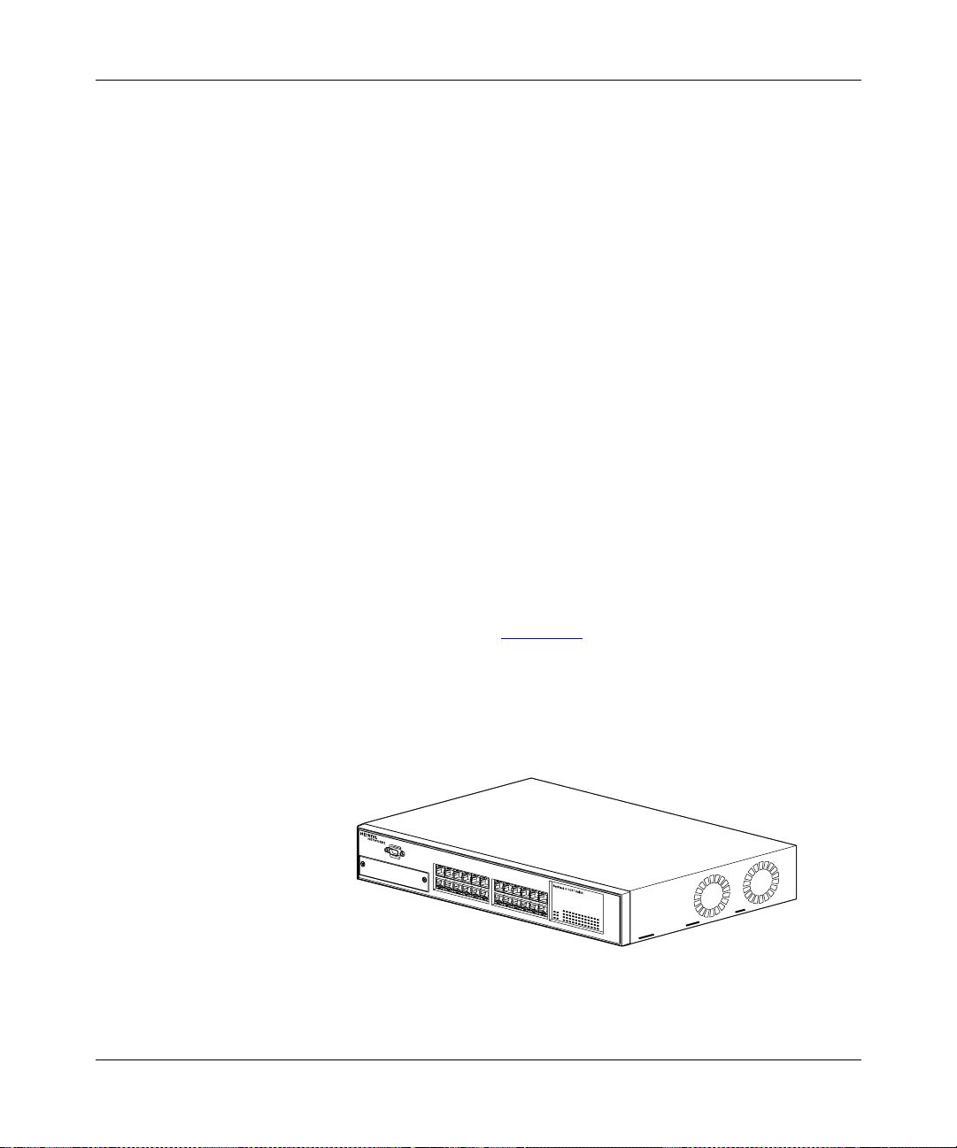
The BayStack 410-24T switch (see Figure 1-1) provides high-performance,
low-cost full-duplex and half-duplex connections to 10BASE-T local area
networks (LANs). With the addition of (optional) media dependent adapters
(MDAs), the BayStack 410-24T switch can support high-speed connections to
servers, shared fast Ethernet hubs, or backbone devices.
BayStack 410-24T
Figure 1-1. BayStack 410-24T Switch
309985-B Rev 00
1
BS41001A
1-1
Page 30
Using the BayStack 410-24T 10BASE-T Switch
Front Panel
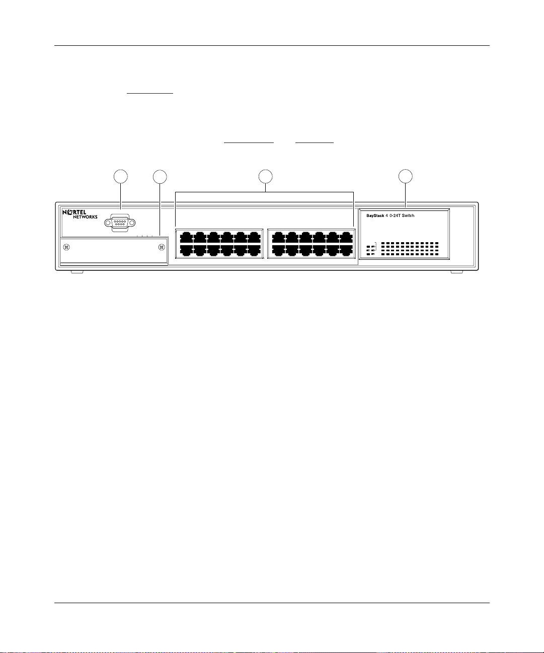
Figure 1-2 shows the BayStack 410-24T switch front panel. Descriptions of the
front panel components follow the figure.
For a description of the components located on the back panel of the BayStack
410-24T switch, see “Back Panel
” on page 1-6.
1
Comm Port
Uplink/Expansion Module
2
2826 2725
5713 9
682 4 10 12
3
11
BayStack 410-24T
1
= Comm Port
2
= Uplink/Expansion slot
3
= 10BASE-T port connectors
4
= LED display panel
Figure 1-2. BayStack 410-24T Switch Front Panel
Comm Port
The Comm Port (also referred to as the Console/Comm Port) allows you to access
the console interface (CI) screens and customize your network using the supplied
menus and screens (see Chapter 3, “Using the Console Interface”).
17 1913 15 21
18 2014 16 22 24
4
1
23
Status
RPSUBase
Cas
Pwr Up
Dwn
Link
Activity
Link
Activity
BS41002A
1-2
The Console/Comm Port is a DB-9, RS-232- D male serial port conn ector . You can
use this connector to connect a management station or console/terminal to the
switch by using a straight-through DB-9 to DB-9 standard serial port cable (see
“Console/Comm Port” on page 2-10).
309985-B Rev 00
Page 31

Introduction to the BayStack 410-24T Switch
The Console/Comm Port is configured as a data communications
Note:
equipment (DCE) connector. Ensure that your RS-232 cable pinouts are
configured for DCE co nnec ti ons (see “DB-9 (RS-232-D) Console/Comm Port
Connector” on page D-5).
The console port default settings are: 9600 baud with eight data bits, one stop bit,
and no parity as the communications format, with flow control set to Xon/Xoff.
Uplink/Expansion Slot
The Uplink/Expansion slot allows you to attach optional media dependent
adapters (MDAs) that support a range of media types (see Appendix B, “Media
Dependent Adapters” for more information about MDA types available from
Nortel Networks).
10BASE-T Port Connectors
The BayStack 410-24T switch uses 10BASE-T (8-pin modular) port connectors.
All BayStack 410-24T switches are shipped with port connectors configured as
MDI-X (media-dependent interface-crossover). These ports connect over straight
cables to the netwo rk interf ace cont roller (NI C) card in a node or serv er, similar to
a conventional Ethernet repeater hub. If you are connecting to another Ethernet
hub or Ethernet switch, you need a crossover cable unless an MDI connection
exists on the associated port of the attached device (see “MDI and MDI-X
Devices” on page D-2).
The switch ports also support half- and full-duplex mode operation (see also
“Connecting 10BASE-T Ports and 10/100 MDA Ports” on page 2-8).
The switch uses RJ-45 port connectors to connect to 10BASE-T Ethernet
segments or nodes.
10BASE-T/100BASE-TX MDA ports (optional) must use Category 5
Note:
UTP cable to accommodate the 100BASE-TX functionality.
See Appendix D, “Connectors and Pin Assignments” for more information about
the RJ-45 port connectors.
309985-B Rev 00
1-3
Page 32

Using the BayStack 410-24T 10BASE-T Switch
LED Display P anel
Figure 1-3
shows the LED di splay panels used wit h the Ba yStack 4 10- 24T switch.
BayStack
Cas
Pwr Up
Dwn
Status
RPSUBase
410-24T Switch
153
2642220 241814 1612810
2119 23
1713 151179
Link
Activity
Link
Activity
BayStack 410-24T
= Dual color LED
BS41003A
Figure 1-3. BayStack 410-24T Switch LED Display Panel
Table 1-1 provides descriptions of the LEDs.
Table 1-1. BayStack 410-24T Switch LED Descriptions
Label Type Color State Meaning
Pwr Power status Green On DC power is available to the switch’s internal circuitry.
Off No AC power to switch, or power supply failed.
Status System status Green On Self-test passed successfully and switch is operational.
Blinking A nonfatal error occurred during the self-test.
Off The switch failed the self-test.
RPSU RPSU status Green On The switch is connected to the HRPSU and can receive
power if needed.
Off The switch is not connected to the HRPSU or HRPSU is
not supplying power.
(continued)
1-4
309985-B Rev 00
Page 33

Introduction to the BayStack 410-24T Switch
Table 1-1. BayStack 410-24T Switch LED Descriptions
Label Type Color State Meaning
CAS Up Stack mode Off The switch is in standalone mode.
Green On The switch is connected to the
In connector.
Yellow On The Cascade A Out con nector (CAS Up) f or this s witc h is
looped internally (wrapped to the secondary ring).
Yellow
or
Green
CAS Dwn Stack mode Off The switch is in standalone mode.
Green On The switch is connected to the
Yellow On The Cascade A In connector (CAS Dwn) for this switch is
Yellow
or
Green
Base Base mode Green On The switch is configured as the stack base unit.
Yellow On This unit is operating as the stack configuration’s
Blinking Incompatible software revision or unable to obtain a unit
ID (Renumber Stack Unit table full). The unit is on the ring
but cannot participate in the stack configuration.
Cascade A Out connector.
looped internally (wrapped to the secondary ring).
Blinking Incompatible software revision or unable to obtain a unit
ID (Renumber Stack Unit table full). The unit is on the ring
but cannot participate in the stack configuration.
Off The switch is
in standalone mode).
Blinking Stack configuration error: Indicates that
units or no base units are configured in the stack.
temporary base unit
if the base unit (directly downstream from this unit) fails.
If this happens, the following events take place:
• The two units directly upstream and directly
downstream from the failed unit automatically wrap
their cascade connectors and indicate this condition
by lighting t hei r Ca s Up and Ca s D wn L E Ds (s ee Cas
Up and Cas Dwn description in this table).
• If the temporary base unit fails, the next unit directly
downstream from this unit becomes the new
temporary base unit. This process can continue until
there are only two units left in the stack configuration.
(continued)
upstream
downstream
configured as the stack base unit (or is
not
. This condition occurs automatically
unit’s Cascade A
unit’s
multiple
base
(continued)
309985-B Rev 00
1-5
Page 34

Using the BayStack 410-24T 10BASE-T Switch
Table 1-1. BayStack 410-24T Switch LED Descriptions
(continued)
Label Type Color State Meaning
This automatic process is a temporary safeguard only. If
the stack configuration loses power, the temporary base
unit will not power up as the base unit when power is
restored. For this reason, you should always assign the
temporary base unit as the base unit (set the Unit Select
switch to Ba se ) u nti l the failed unit is re pai red or replaced.
Link 10 Mb/s port
speed indicator
Green On The corresponding port is set to operate at 10 Mb/s and
the link is good.
Green Blinking The corresponding port has been disabled by software.
Off The link connection is bad or there is no connection to
this port.
Activity Port activity Green Blinking Indicates network activity for the corresponding port. A
high level of network activity can cause the LEDs to
appear to be on continuously.
Back Panel
This section describes the BayStack 410-24T switch back panel components
(Figure 1-4
).
Descriptions of the back panel components follow the figure.
1
100-240V~
47-63HZ~
1.5A-600ma
1
= AC power receptacle
2
= RPSU connector
3
= Cascade Module Slot
Figure 1-4. BayStack 410-24T Switch Back Panel
1-6
Redundant Power
3
Cascade Module
2
BS41004A
309985-B Rev 00
Page 35

228FA
Introduction to the BayStack 410-24T Switch
AC Power Receptacle
The AC power receptacle accepts the AC power cord (supplied). For installation
outside of North Ameri ca, make sure that you ha v e the prop er po wer cord for you r
region. Any cord used must have a CEE-22 standard V female connector on one
end and must meet the IEC 320-030 specifications.
Table 1-2
lists speci fications for international power cords.
Table 1-2. International Power Cord Specifications
Country/Plug description Specifications Typical plug
Australia:
• AS3112-1981 Male plug
Continental Europe:
• CEE7 standard VII male plug
• Harmonized cord (HAR marking
on the outside of the cord jacket
to comply with the CENELEC
Harmonized Document HD-21)
U.S./Canada/Japan:
• NEMA5-15P male plug
• UL recognized (UL stamped
on cord jacket)
• CSA certified (CSA label
secured to the cord)
United Kingdom:
• BS1363 male plug with fuse
• Harmonized cord
240 VAC
50 Hz
Single phase
220 or 230 VAC
50 Hz
Single phase
100 or 120 VAC
50–60 Hz
Single phase
240 VAC
50 Hz
Single phase
230FA
227FA
309985-B Rev 00
229FA
1-7
Page 36

Using the BayStack 410-24T 10BASE-T Switch
RPSU Connector
The RPSU connector allows you to connect a backup power supply unit to the
switch. Nortel Networks provides an (optional) high-power redundant power
supply unit (HRPSU) for this purpose. The HRPSU is a hot-swappable power
supply unit that provides uninterrupted operation to up to four BayStack 410-24T
switches in the event that any of the switch power supplies fail.
Nortel Networks provides the HRPSU power rack (Order No. AA0002001) with
four slots for power supply modules (Order No. AA0005003). Each HRPSU can
support up to four BayStack 410-24T switches. Installation instructions are
provided with the HRPSU.
Contact your Nortel Ne tw orks sales repre sen tative for more info rmatio n about the
HRPSU.
Cascade Module Slot
The Cascade Module slot allows you to attach an optional BayStack 400-ST1
Cascade Module to the switch (see “
You can connect up to eight BayStack 410-24T switches into a redundant stack
configuration. BayStack 410-24T switches use a fail-safe cascade stacking
architecture whic h, in the unlik ely ev ent of a swit ch failur e, maintains the integ rity
of the remaining stack: all signals are looped back at the point of failure. Because
each unit in the stack has a full copy of the stack configuration, operation of the
stack continues without affecting application connectivity.
Stack Operation” on page 1-27).
1-8
Any mix of up to eight BayStack 410-24T switches and BayStack 450 switches
can be stacked to provide a total of 224 ports (when all MDA slots are configured
with the maximum port availability).
Installation instructions are provided with each BayStack 400-ST1 Cascade
Module (see Installing the BayStack 400-ST1 Cascade Module). See your Nortel
Networks sales represen tative for ordering information.
Cooling Fans
The variabl e- spe ed co oli ng fans (not shown) are loc at ed on on e si de of the switch
to provide cooling for the internal components. When you install the switch, be
sure to allow enough space on both sides of the switch for adequate air flow.
309985-B Rev 00
Page 37

Features
Introduction to the BayStack 410-24T Switch
BayStack 410-24T switches offer the following features:
• High-speed forwarding rate: Up to 1 million packets per second (peak)
• Store-and-forward switch: Full -performance forwarding at full line speed,
utilizing a 1.28 Gigabit/second switch fabric
• Learning rate: 1 million addresses per second (peak)
• Address database size: 16,000 entries at line rate (32,000 entries without
flooding)
• Fail-safe stacking: Provides uninterrupted connectivity for up to eight units,
with up to 224 ports stacked together as one managed unit (requires one
optional BayStack 400-ST1 Cascade Module kit per stacked unit. See your
Nortel Netwo r ks sales repr esentative for ordering informat ion).
• Spanning Tree Protocol (STP): Complies with IEEE 802.1D standard. STP
can be disabled on the entire switch or stack, or on a per-port basis.
• SNMP agent support for the following management information bases
(MIBs):
309985-B Rev 00
-- SNMPv2 (RFC 1907)
-- Bridge MIB (RFC 1493)
-- Ethernet MIB (RFC 1643)
-- RMON MIB (RFC 1757)
-- MIB-II (RFC 1213)
-- Interface MIB (R FC 1573)
-- Nortel Networks proprietary MIBs:
- s5Chas MIB
- s5Agent MIB
- Rapid City MIB
• High-speed uplink/expansion slot: Allows you to attach optional media
dependent adapters (MDAs) that support a range of media types.
• Rate limiting: Adjustable broadcast or IP Multicast packet-rate limits for
control of broadcast and IP Multicast storms.
1-9
Page 38

Using the BayStack 410-24T 10BASE-T Switch
• Console/Comm port: Allo ws use rs to c onf igure and manage the swit ch local ly
or remotely.
• Virtual local area networks (VLANs), supporting:
-- IEEE 802.1Q port-based VLANs
-- Protocol-based VLANs
• TELNET:
-- Support for up to four simultaneous TELNET sessions
-- Optional password protection
-- Login time-out
-- Failed-logi n guard
-- Inactivity time-out
-- Allowed source addresses
-- Event logging
• IEEE 802.1Q port-based virtual LANs (VLANs)
• IGMP snooping
1-10
• IEEE 802.1p prioritizing
• MultiLink Trunking, supporting:
-- Switch-to-switch trunks
-- Switch-to-server trunks
• Port mirroring (conversation steering)
-- Port-based
-- MAC address-based
• IEEE 802.3u-compliant optional MDA autonegotiation ports, with four
modes:
-- 10BASE-T half-duplex
-- 10BASE-T full- duplex
-- 100BASE-TX half-duplex
-- 100BASE-TX full-duplex
309985-B Rev 00
Page 39

Introduction to the BayStack 410-24T Switch
• Front panel light-emitting diodes (LEDs) to monitor the following:
-- Power status
-- System status
-- Stack status for the following:
- Cascade Up and Cascade Down status
- Base unit status
-- RPSU status
-- Per-port status for the following:
- 10 Mb/s link
- Tx/Rx activity
- Manageme nt enable/disable
• Upgradeable device firmware in nonvolatile flash memory using the Trivial
File Transfer Protocol (TFTP)
• Configuration file download/upload support: Allows you to store your switch/
stack configuration parameters on a TFTP server.
309985-B Rev 00
• Remote monitoring (RMON), with four groups integrated:
-- Statistics
-- History
-- Alarms
-- Events
• Security:
-- MAC address-based security: Allows you to limit access to the switch
based on MAC addresses.
-- RADIUS network security: Allows you to set up your switch with
RADIUS-based (Remote Authentication Dial-In User Services) security,
for authenticating local console and TELNET logins.
1-11
Page 40

Using the BayStack 410-24T 10BASE-T Switch
Virtual Local Area Networks (VLANs)
In a traditional shared-media network, traffic generated by a station is propagated
to all other stations on the local segment. Therefore, for any given station on the
shared Ethernet, the local segment is the collision domain because traffic on the
segment has the pote ntial to cause an Ethernet colli sion. The l ocal se gment is also
the broadcast domain because any broadcast is sent to all stations on the local
segment. Although Ethernet switches and bridges divide a network into smaller
collision domains, they do not affect the broadcast domain. In simple terms, a
virtual local area network provides a mechanism to fine-tune broadcast domains.
Your BayStack 410-24T switch allows you to create two types of VLANs:
• Port-based VLANs
A port-based VLAN is a VLAN in which the ports are explicitly configured to
be in the VLAN. When you create a port-based VLAN, you assign a Port
VLAN Identifier (PVID) and specify which ports belong to the VLAN. The
PVID is used to coordinate VLANs across multiple switches.
• Protocol-based VLANs
A protocol-based VLAN i s a VLAN in which you assign your swit ch por ts as
members of a broadcast doma in, base d on the pr otocol infor mati on with in the
packet. Protocol-based VLANs can localize broadcast traffic and assure that
only the protocol-based VLAN ports are flooded with the specified protocol
type packets.
1-12
Your switch ports can be members of mul tiple p rotocol-bas ed VLANs th at are
not based on the same protocol. Only tagged ports can be members of
multiple protocol-based VLANs that are based on the same protocol.
BayStack 410-24T switches support up to 64 port-based or protocol-based
VLANs. When a switch port is conf igure d to be a member of a VLAN, it is added
to a group of ports (workgroup) that belong to one broadcast domain. You can
assign different ports (and therefore the devices attached to these ports) to
different broadcast domains. This feature allows network flexibility because you
can reassign VLANs to accommodate network moves, additions, and changes,
eliminating the need to change physical cabling.
For more information about VLANs, see “
page 1-36
.
IEEE 802.1Q VLAN Workgroups” on
309985-B Rev 00
Page 41

Security
Introduction to the BayStack 410-24T Switch
Your BayStack 410-24T switch security feat ure can pro vid e two levels of security
for your local area network (LAN):
• RADIUS-based security -- Limits admin is tr at ive access to the swi tc h through
user authentication.
• MAC address-based security -- Limits access to the switch based on allowed
source MAC addresses.
Figure 1-5
shows a typical campus configuration using the BayStack 410-24T
switch security features. This example assumes that the switch, the teachers’
offices and classrooms, and the library are physically secured. The student
dormitory may (or may not be) physically secure.
RADIUS server
To Network
Center
Switch
Student Dormitory
Teachers’ offices
and classrooms
RADIUS-based
security
Legend
= Secure locked area
Library
Figure 1-5. BayStack 410-24T Switch Security Feature
309985-B Rev 00
BS41077A
1-13
Page 42

Using the BayStack 410-24T 10BASE-T Switch
In this configuration example, the following security measures are implemented:
• The switch
-- RADIUS-based security is used to limit administrative access to the switch
through user authentication (see “
page 1-15
).
-- MAC address-based security is used to allow up to 448 authorized stations
(MAC addresses) access to one or more switch ports
MAC Address-Based Security” on page 1-15).
(see “
-- The switch is located in a locked closet, accessible only by authorized
Technical Services personnel.
• Student dormitory
Dormitory rooms are typically occupied by two students and have been
prewired with two RJ-45 jacks. Only students who are authorized (as
specified by the MAC address-based security feature) can access the switch
on the secured ports.
• Teachers’ offices and classrooms
The PCs that are located in the teacher s’ offices and in the classrooms are
assigned MAC address-based security that is specific for each classroom and
office location. The security feature logically locks each wall jack to the
specified station and prevents unauthorized access to the switch should
someone attempt to connect a personal laptop PC into the wall jack. The
printer is assigned as a single station and is allowed full bandwidth on that
switch port.
RADIUS-Based Network Security” on
1-14
It is assumed that all PCs are password protected and that the classrooms and
offices are physically secured.
• Library
The wall jacks in the lib rary are set up so that the PCs can be connected to any
wall jack in the room. Thi s allo ws the PCs to be mov ed an ywhere in th e room.
The exception is the printer, which is assigned as a single station with full
bandwidth to that port.
It is assumed that all P Cs are p ass word pro tecte d and th at acc ess to th e libr ary
is physically secured.
309985-B Rev 00
Page 43

RADIUS-Based Network Security
The RADIUS-based security feature allows you to set up network access control,
using the RADIUS (Remote Authentication Dial-In User Services) security
protocol. The RADIUS-based security feature uses the RADIUS protocol to
authenticate local console and TELNET logins.
You will need to set up specific user accounts (user names and passwords, and
Service-Type attributes) on your RADIUS server before the authentication
process can be initiated. To provide each user with appropriate levels of access to
the switch, set the following username attributes on your RADIUS server:
• Read-write access -- Set the Service-Type field value to Administrative.
• Read-only access -- Set the Service-Type field value to NAS-Prompt.
For detailed instructions about settin g up your RAD IUS server, refer to your
RADIUS server documentati on.
For instructions on using the console interface (CI) to set up the Radius-based
security feature, see “Console/Comm Port Configuration” on page 3-82.
Introduction to the BayStack 410-24T Switch
MAC Address-Based Security
The MAC address-based security feature allows you to set up network access
control, based on source MAC addresses of authorized stations.
You can:
• Create a list of up to 448 MAC addresses and specify which addresses are
authorized to connect to your switch or stack configuration. The 448 MAC
addresses can be configured within a single standalone switch or they can be
distributed in any order among the units in a single stack configuration.
• Specify which of your switch ports each MAC address is allowed to access.
The options for allowed port access include: NONE, ALL, and single or
multiple ports that are specified in a li st , for example, 1/1-4,1/6 ,2/9 (see “Port
List Syntax” on page 3-33).
• Specify optional actions to be e x e rcised b y your swit ch if the softw ar e detec ts
a security violation.
The response can be to sen d a trap, turn on destination addres s ( DA) filtering,
disable the specific port, or any combination of these three options.
309985-B Rev 00
1-15
Page 44

Using the BayStack 410-24T 10BASE-T Switch
For instructions on using the console interface (CI) to set up network access
control, see “MAC Address-Based Security” on page 3-22.
The MAC address-based security feature is based on Nortel Networks
BaySecure
™
LAN Access for Ethernet, a real-t ime securi ty sys tem that sa fegu ards
Ethernet networks from unauthorized surveillance and intrusion.
To learn more about the Nortel Networks BaySecure LAN Access for Ethernet,
refer to the Bay Networks Guide to Implementing BaySecure LAN Access fo r
Ethernet (Part number 345-1106A).
IEEE 802.1p
The BayStack 410-24T switch can prioritize the order in which packets are
forwarded, on a per-port basis.
For more information about the IEEE 802.1p prioritizing feature, see “
802.1p Prioritizing” on page1-57.
IGMP Snooping Feature
For conserving bandwidth and controlling IP Multicast, the IGMP snooping
feature can provide the same benefit as IP Multicast routers, but in the local area.
For more infor mation about th e IGMP snooping feature, see “
page 1-52
.
Configuration and Switch Management
The BayStack 410-24T switch is shipped directly from the factory ready to
operate in any 10BASE-T network. Optional MDAs are available for connecting
to 100BASE-T networks. You can manage the switch using the Nortel Networks
Optivity
Software, or any generic SNMP-based network management software; however,
you must assign an IP address to the switch or stack, depending on the mode of
operation. You can set both addresses by using the Console/Comm Port or BootP,
which resides on the switch. For more information about using the Console/
Comm Port to configure the switch, see Chapter 3, “Using the Console Interf ace . ”
®
network management software, Nortel Networks Device Manager
IEEE
IGMP Snooping” on
1-16
309985-B Rev 00
Page 45

Flash Memory Storage
The following two sections describe switch parameters that are stored in flash
memory.
Switch Software Image
Your switch’s sof twar e imag e is store d in f lash memory. The flash memory allows
you to update your s witch soft war e image wi th a ne we r v ersi on, with out cha nging
the switch hardware (see “Software Download” on page 3-102). An in-band
connection between the switch and the TFTP load host is required to download
the software image.
If a BootP server is set up properly on the network and the BayStack 410-24T
switch detects a corrupted software image during the self-test, the switch
automatically uses TFTP to download a new software image.
Configuration Parameters
Introduction to the BayStack 410-24T Switch
309985-B Rev 00
Certain configuration parameters, including the system characteristics strings,
some VLAN parameters, IGMP configuration parameters, and the MultiLink
Trunk names are stored in flash memory. These parameters are updated every 10
minutes or whenever you issue the Reset command.
Note:
Do not power off the switch within ten minutes of changing any
configuration parameters, unless you first issue the Reset command. Powering
down the switch within 10 minutes of changing configuration parameters
(without resetting) can cause the changed configuration parameters to be lost.
1-17
Page 46

Using the BayStack 410-24T 10BASE-T Switch
Autosensing and Autonegotiation
BayStack 410-24T switches are autosensing and autonegotiating devices. The
term autosense refers to a port’s ability to sense the speed of an attached device.
The term autonegotiation refers to a standardized protocol (IEEE 802.3u) that
exists between two IEEE 802.3u-capable devices.
Because the BayStack 410-24T switch uses fixed 10BASE-T ports, the
autonegotiation feature does not negotiate the port speed when connecting to
another IEEE 802.3u-capable device. The BayStack 410-24T switch only
negotiates the best duplex mode.
When an optional 10/100 BASE-T MDA is installed, the autonegotiation feature
selects the best of both speed and duplex modes for that connection. The MDA
ports negoti ate do wn fro m 100 Mb/s speed a nd full- duple x mode until a supporte d
speed and duplex mode is acknowledged by the attached device.
Autosensing is use d whe n t he attached device is n ot capable of autonegotiat i on or
is using a form of autonegotiation that is not compatible with the IEEE 802.3u
autonegotiation standard. In this case, because it is not possible to sense the
duplex mode of the attached device, the BayStack 410-24T switch reverts to
half-duplex mode.
For more information about autosensing and autonegotiation modes, see
“Autonegotiation Modes” on page 4-7.
MultiLink Trunking
The MultiLink Trunking feature allows you to group multiple ports (up to four)
together when forming a link to another switch or server, thus increasing
aggregate thr oughp ut of the intercon nect ion bet ween tw o devices (up to 800 Mb/s
in full-duplex mode when an optional 100BASE-T MDA is installed). BayStack
410-24T switches can be configured with up to six MultiLink Trunks. The trunk
members can be conf igure d within a single uni t in the stack or distr ib uted betwee n
any of the units within the stack configuration (distributed trunking).
For more information about the MultiLink Trunking feature, see “MultiLink
Trunks” on page 1-61.
1-18
309985-B Rev 00
Page 47

IEEE 802.1Q VLANs
BayStack 410-24T switches support up to 64 port-based VLANs with IEEE
802.1Q tagging available per port.
When a switch port is configured to be a member of a VLAN, it is added to a
group of ports (workgroup) that belong to one broadcast domain. You can assign
different ports (and therefore the devices attached to these ports) to different
broadcast domains.
This feature allows network flexibility because you can reassign VLANs to
accommodate network moves, additions, and changes, eliminating the need to
change physical cabling.
Introduction to the BayStack 410-24T Switch
For more information about 802.1Q VLANs, see “
Workgroups” on page 1-36.
Port Mirroring
The port mirroring featu re (sometimes referred to as conversation ste ering) allows
a user to designate a single swit ch por t as a tr affic monitor for up to two speci fied
ports or two media access control (MAC) addresses.
You can specify Port-Based monitoring, where all traffic on specified ports is
monitored, or Address-Based monitoring, where traffic between specified MAC
addresses is monitored.
You can attach a probe device (such as a Nortel Networks StackProbe, or
equivalent) to the designated monitor port.
For more information about the port mirroring feature, see “P
(Conversation Steering)” on page 1-80.
IEEE 802.1Q VLAN
ort Mirroring
309985-B Rev 00
1-19
Page 48

Using the BayStack 410-24T 10BASE-T Switch
BootP Automatic IP Configuration/MAC Address
The BayStack 410-24T switch has a unique 48-bit hardware address, or MAC
address, that is printed on a label on the back panel. You use this MAC address
when you confi gure the ne twor k BootP server to recognize the BaySt ack 41 0-24 T
switch BootP requests.
A properly configured BootP server enables the switch to automatically learn its
assigned IP address, subnet mask, IP address of the default router (default
gateway), and software image file name.
When the switch is participating in a stack configuration, a Stack MAC address is
automatically assigned during the stack initialization. The base unit’s MAC
address, with a software offset, is used fo r the Stack M AC address.
For example, if the base unit’s MAC address is:
00-00-82-99-44-00
and the Stack software offset is:
1F
1-20
then the Stack MAC address becomes:
00-00-82-99-44-1F
If another unit in the stack is assigned as the base unit, the MAC address of the
new base unit (with offset) now applies to the stack configuration. The original
stack IP address still applies to the new base unit.
For an example of a BootP configuration file, see Appendix F, “Sample BootP
Configuration Fil e. ”
309985-B Rev 00
Page 49

SNMP MIB Support
The BayStack 410-24T switch supports an SNMP agent with industry standard
MIBs, as well as private MIB extensions, which ensures compatibility wi th
existing network management tools. The BayStack 410-24T switch supports the
MIB-II (RFC 1213), the Bridge MIB (RFC 1493), and the RMON MIB (RFC
1757), which provide access to detailed management statistics.
Introduction to the BayStack 410-24T Switch
For a complete listing of supported MIBs, see “
For details on SNMP trap support, see “
SNMP Trap Support” following this
Features” on page 1-9.
section.
SNMP Trap Support
The BayStack 410-24T switch supports an SNMP agent with industry standard
SNMPv1 traps, as well as private SNMPv1 trap extensions (Table 1-3
Table 1-3. Supported SNMP Traps
Trap Name Configurable Sent when:
RFC 1215 (I ndustry Standard):
linkUp Per port A port’s link state changes to up.
linkDown Per port A port’s link state changes to down.
authenticationFailure System wide There is an SNMP authentication failure.
coldStart Always on The system is powered on.
warmStart Always on The system restarts due to a management reset.
s5Ctr MIB (Nortel Networks Proprietary Traps):
s5CtrUnitUp Always on A unit is added to an operational stack.
s5CtrUnitDown Always on A unit is removed from an operational stack.
s5CtrHotSwap Always on A unit is hot-swapped in an operational stack.
s5CtrProblem Always on An assigned base unit fails.
).
309985-B Rev 00
1-21
Page 50

Using the BayStack 410-24T 10BASE-T Switch
Network Configuration
You can use BayStack 410-24T switches to connect workstations, personal
computers (PCs), a nd ser ve rs t o each ot her b y connect ing t hese devices directly to
the switch, through a shared media hub that is connected to the switch, or by
creating a virtual LAN (VLAN) through the switch.
This section provides four network configuration examples using BayStack
410-24T switches:
• Desktop switch application
• Segment switch application
• High-density switched workgroup application
• Fail-safe stack applicat ion
Desktop Switch Application
Figure 1-6 shows the BayStack 410-24T switch used as a desktop switch, where
desktop workstations are connected directly to switch ports.
1-22
This configuration uses the optional 400-4TX MDA (10BASE-T/100BASE-TX)
and provides dedicated 100 Mb/s connections to the network center, to the server,
and for two users. Twenty-four users are provided with dedicated 10 Mb/s
connections.
309985-B Rev 00
Page 51

10BASE-T hub
Introduction to the BayStack 410-24T Switch
Before After
BayStack 410-24T switch
Up to 24
10 Mb/s users
Server Up to 22 users
To
Network
Center
Key
10 Mb/s
100 Mb/s
200 Mb/s
- 22 users share 10 Mb/s (10/22 Mb/s per user)
- Server bottleneck (10 Mb/s bandwidth)
- Network center bottleneck (10 Mb/s bandwidth)
- 24 users with dedicated 10 Mb/s bandwidth
- 2 users with dedicated 100 Mb/s bandwidth
- Server with dedicated 100 Mb/s bandwidth
- Network center with dedicated 100 Mb/s full-duplex
bandwith (200 mb/s bidirectional)
Server
To
Network
Center
Figure 1-6. BayStack 410-24T Switch Used as a Desktop Switch
2 additional
100 Mb/s users
BS41005A
309985-B Rev 00
1-23
Page 52

Using the BayStack 410-24T 10BASE-T Switch
Segment Switch Application
Figure 1-7 shows the BayStack 410-24T switch used as a segment switch to
alleviate user contention for bandwidth and eliminate server and network
bottlenecks. Befo re segmentation, 88 use rs had a total bandwidth of o nly 10 Mb/s
available. After segmentation, 114 users have 40 Mb/s, four times the previous
bandwidth, while adding 22 dedicated 10 Mb/s connections. This configuration
can be extended to add more segments without degrading performance.
Before
10BASE-T hubs
Server
To
Network
Center
Key
10 Mb/s
100 Mb/s
200 Mb/s
- 88 users share 10 Mb/s (10/88 Mb/s per user)
- Server bottleneck (10 Mb/s bandwidth)
- Network center bottleneck (10 Mb/s bandwidth)
- Total of 88 users
Up to
88 users
After
Server
Network
Center
- Four sets of 23 users; each set shares 10 Mb/s
(10/23 Mb/s per user)
- Addition of 22 users; each with dedicated
10 Mb/s bandwidth
- Server with dedicated 100 Mb/s full-duplex bandwidth
(200 Mb/s bidirectional
- Network center with dedicated 100 Mb/s full-duplex bandwidth
(200 Mb/s bidirectional)
- Total of 114 users
BayStack 410-24T switch
To
Up to 22
users
Up to 23
users
Up to 23
users
Up to 23
users
Up to 23
users
BS41006A
Figure 1-7. BayStack 410-24T Switch Used as a workgroup Switch
1-24
309985-B Rev 00
Page 53

Introduction to the BayStack 410-24T Switch
High-Density Switched Workgroup Application
Figure 1-8 shows a BayStack 410-24T switch using an (optional) 400-4TX MDA
to connect to a BayStack 450 switch. The Baystack 450 switch provides a
high-speed connection t o a Nortel Netw orks Accela r
and 304 switches are also shown in this high-density workgroup example.
The Accelar 1100 switch is used as a backbone switch, connecting to the
BayStack 450 switch configured with a gigabit (1000BASE-SX) MDA for
maximum bandwidth. The BayStack 303 and 304 switches have 100 Mb/s
connections to the BayStack 410-24T switch, a 100BASE-TX hub, and a
100 Mb/s server and 10 Mb/s connections to DTE (data terminal equipment).
See the Nortel Networks library Web page: support.baynetworks.com/library/ for
online documentation about the Nortel Networks Accelar 1100 switch and the
BayStack 303 and 304 switches.
™
1100 switch. BayStack 303
BayStack 410-24T
BayStack 450 switch
F
CPUPS1 PS2FAN
Accelar switch
Key
10 Mb/s
100 Mb/s
1000 Mb/s
(Gigabit)
switch
303
F
Server
304
Figure 1-8. Configuring Power Workgroups and a Shared Media Hub
309985-B Rev 00
BayStack 303
switch
100BASE-TX
hub
BayStack 304
switch
BS41007A
1-25
Page 54

Using the BayStack 410-24T 10BASE-T Switch
Fail-Safe Stack Application
Figure 1-9 shows eight switches (a single BayStack 450 switch and seven
BayStack 410-24T switc hes) t hat ar e stac k ed tog ether as a si ngle mana ged u nit. I f
any unit in the stack fails, the remaining stack remains operational.
As shown in Figure 1-9
, an Accelar 1100 switch is used as a backbone switch,
connecting to a BayStack 450 switch with an optional gigabit 1000BASE-SX
MDA for maximum bandwidth (the BayStack 410-24T switch does not support
gigabit MDAs).
This configuration uses optional BayStack 400-ST1 Cascade Modules to connect
the switches in t he fai l-safe stack.
that is available for the BayStack 410-24T switches, see
For an overview of the fail-s afe stac king feat ure
“
Stack Operation
”
following this section.
Accelar switch
CPUPS1 PS2FAN
F
BayStack 450-24
BayStack 410-24T
BayStack 410-24T
BayStack 410-24T
BayStack 410-24T
BayStack 410-24T
BayStack 410-24T
BayStack 410-24T
T
Up to
24 users
Up to
28 users
Up to
28 users
Up to
28 users
Up to
28 users
Up to
28 users
Up to
28 users
1-26
Up to
28 users
BS41008A
Figure 1-9. Fail-Safe Stack Example
309985-B Rev 00
Page 55

Stack Operation
BayStack 410-24T switches provide fail-safe stacking when you install the
optional BayStack 400-ST1 Cascade Module (see “
on page 1-26
connectivity for up to 224 ports. The entire stack is manageable as a single unit.
Installation ins tructions a re provided with the BaySt ack 400-ST1 Casc ade Module
(see your Nortel Networks sales representative for ordering information).
BayStack 400-ST1 Cascade Module
The front panel components of t he BayStack 40 0-ST1 Casc ade Module are sho wn
in Figure 1-10
Component descriptions follow the figure.
). You can connect up to eight switches to provide uninterrupted
.
1
Introduction to the BayStack 410-24T Switch
Fail-Safe Stack Application”
309985-B Rev 00
Cascade A Out
2
1 = Blank connectors (unused)
2 = Cascade A Out connector
3 = Unit Select switch
4 = Cascade A In connector
Unit Select
3
Base
Cascade A In
4
BS41009A
Figure 1-10. BayStack 400-ST1 Front Panel Components
1-27
Page 56

Using the BayStack 410-24T 10BASE-T Switch
Cascade A Out Connector
Provides an attachment point for connecting this unit to another unit via the
cascade cable. A return cable from another u nit’s Cascade A Out connector to this
unit’s Cascade A In connector completes the stack connection (see the example
shown in Figure 1-11
).
Unit Select Switch
The Unit Select switch (up = Base) determines the base unit for the stack
configuration (see “
Initial Installation” on page 1-29). The Unit Select switch
status is displayed on the BaySt ack 410- 24T switc h LED displa y panel. When the
Unit Select switch i s in the Ba se (up) p osition, all other Unit Select switches in th e
stack configuration must be set to Off (down).
Cascade A In Connector
Provides an attachment point for accepting a cascade cable connection from an
adjacent unit in the st ack. A return cable from this unit’s Cascade A Out connector
to the adjacent unit’s Cascade A In con nector completes the stack c onne ct ion (see
the example shown in Figure 1-11
).
1-28
Cascade A Out
Cascade A Out
Cascade A Out
Cascade Module
Cascade A InUnit Select
Cascade Module
Cascade A InUnit Select
Unit 1
Unit 2
1 = Base unit
2 = 303978-A cascade cable
3 = 303978-A cascade cable (used for return)
Redundant Power
Redundant Power
32
Figure 1-11. Connecting Cascade Cables
Cascade A In
1
BS41010A
309985-B Rev 00
Page 57
Base Unit
Introduction to the BayStack 410-24T Switch
Note:
For stacking thr ee or more units (maximum 8 units per st ac k), order the
optional 1 meter (3.28 ft.) cascade return cable (Order No. AL2018001).
The base unit is the unique stack unit that is configured by the Unit Select switch
on the front panel of the 400-ST1 cascade module. One unit in the stack must be
configured as th e bas e uni t; all other units in the stack must have their Unit Select
switch set t o Off (see “
Unit Select Switch” on page 1-28). Any single unit in the
stack can be assigned as the base unit.
Note:
Although any single unit in the stack can be assigned as the base unit,
when mixing BayStack models in a single stack, Nortel Networks
recommends that you assign the unit with the highest bandwidth as the base
unit. The additi ona l workload of the base uni t is optimized by using the higher
bandwidth model switch.
309985-B Rev 00
The physical ordering of all of the other units in the stack is determined by the
position of the base unit within the stack. This is important for management
applications that view the physical ordering of the units within the stack.
Some characteristics of the base unit are described in the following sections.
Initial Installation
During the initial installation of the stack, the software automati cally determines
the physical ord er of all units in t he stack ac cordi ng to the pos ition of t he base uni t
within the stack. Thereafter, the individual units maintain their original unit
numbering, even if the position of one or more units in the stack is changed (you
can renumber the units using the Renumber Stack Units screen; see “Renumber
Stack Units” on page 3-89).
For example, when the stack is initially powered up, the base unit becomes unit 1
and the unit that the base unit connects to (via the Cascade A Out cable) becomes
unit 2 (and the next unit is unit 3 and so on), until the maximum stack
configuration (up to 8 units) is reached. If the base unit is changed to another unit
in the stack, the new base unit keeps its original unit number in the stack.
1-29
Page 58

Using the BayStack 410-24T 10BASE-T Switch
Stack MAC Address
The Stack MAC address is automatically assigned during the stack initialization.
The base unit’s MAC address, with a software offset, is used for th e Stack MAC
address.
For example, if the base unit’s MAC address is:
00-00-82-99-44-00
and the Stack software offset is: 1F
then the Stack MAC address becomes:
00-00-82-99-44-1F
If another unit in the stack is assigned as the base unit, the MAC address of the
new base unit (with offset) now applies to the stack configuration. The original
stack IP address still applies to the new base unit.
Temporary Base Unit
1-30
If an assigned base unit fails, the next unit in the stack order automatically
becomes the new t emporary base unit. This change is indicated by the Base LED
on the temporary base unit’s LED display panel turning on (yellow). For detailed
information about the base LED, see Table 1-1
on page 1-4.
This automatic process is a temporary safeguard only. If the stack configuration
loses power, the temporary base unit will not power up as the base unit when
power is restored. For this reason, you should always assign the temporary base
unit as the base unit (set the Unit Select switch to Base) until the failed unit is
repaired or replaced.
If you do not reassign the temporary base unit as the new base unit, and
Note:
the temporary base unit fails, the next unit directly downstream from this unit
becomes the new temporary base unit. This process can continue until there
are only two units left in the stack configuration.
309985-B Rev 00
Page 59

Removing a Unit from the Stack
If a unit is removed from the stack (therefore operating in standalone mode), the
following switch configuration settings revert back to the settings configured
before the u nit became a member of the stack:
• IP address
• Console password
• TELNET password
• SNMP community strings
Stack Configurations
As shown in Figure 1-12, the cascade connectors and c abl es on t he 400-ST1 front
panel provide the ability to stack up to eight BayStack switches. With 400-4TX
MDAs installed in each switch, the stack can accommodate a maximum of 224
switch ports.
Introduction to the BayStack 410-24T Switch
Because stack parameters are associated with the base unit (see “
Initial
Installation” on page 1-29), the physical stack order depends on the base unit’s
position and whether the stack is configured stack up or stack down.
309985-B Rev 00
1-31
Page 60

Using the BayStack 410-24T 10BASE-T Switch
Stack Up Configurations
In Figure 1-12
, data flows from the base unit (unit 1) to the next switch, wh ich is
assigned as unit 2, and continues until the last switch in the stack is assigned as
unit 8. The physical order of the switches is from bottom to top (unit 1 to unit 8).
t
u
1
2
O
Unit 8
Unit 7
Unit 6
Unit 5
Unit 4
Unit 3
Unit 2
Unit 1
I
n
1-32
1 = Last unit
2 = Base unit
3 = Cascade cable (PN 303978-A)
4 = Cascade max-return cable (PN 303979-A)
3
4
BS41011A
Figure 1-12. Stack Up Configuration Example
Stack Down Configurations
In Figure 1-13
, data flows from the base unit (unit 1) to the next switch, wh ich is
assigned as unit 2, and continues until the last switch in the stack is assigned as
unit 8. The physical order of the switches is from top to bottom (unit 1 to unit 8).
309985-B Rev 00
Page 61

Introduction to the BayStack 410-24T Switch
1
2
1 = Base unit
2 = Last unit
3 = Cascade cable (PN 303978-A)
4 = Cascade max-return cable (PN 303979-A)
3
Unit 1
n
I
Unit 2
Unit 3
Unit 4
Unit 5
Unit 6
Unit 7
Unit 8
O
u
t
4
BS41012A
309985-B Rev 00
Figure 1-13. Stack Down Configuration Example
Certain network management station (NMS) applications assume a stack-down
configuration for the graphical user interface (GUI) that represents the stack (see
Figure 1-13
on page 1-33). For this r eason, Nortel Netw orks recommends t hat you
always configure the top unit in the stack as the base unit.
In any stack configuration, the following applies:
• The entire stack powers up as a sin gle logi cal unit within 30 seconds after the
base unit initialization.
• You can attach an RS-232 communications cable to the Console/Comm port
of any switch in the stack.
1-33
Page 62

Using the BayStack 410-24T 10BASE-T Switch
• You can downline upgrade the entire stack from any switch in the stack.
• You can access and manage the stack using a TELNET connection or any
generic SNMP management tool through any switch port that is part of the
stack configuration.
• When stacking three or more switches, use the longer (1-meter) cascade
max-return cable (PN 30 3979-A) t o complete th e li nk from th e last unit in t he
stack to the base unit.
Redundant Cascade Stacking Feature
BayStack 410-24T Switches allow you to connect up to 8 units into a redundant
cascade stack. If an y sing le unit f ails or if a cable is ac cidently disconn ected, othe r
units in the stack remain operational, without interruption.
Figure 1-14
shows an example of how a stack configuration reacts to a failed or
powered-down unit in the stack configuration:
1.
As shown in Figure 1-14, unit 3 is not operational.
This can be the result of a fail ed unit, or simply becau se the unit wa s po wered
down.
2.
Unit 2 and unit 4, directly upstream and downstream from unit 3, sense the
loss of link signals from unit 3.
• Unit 2 and unit 4 automatically loop thei r inte rnal st ack sig nal s (A and B).
• The Cas Up LED for unit 2 and the Cas Dwn LED for unit 4 turn on
(yellow) to indicate that the stack signals are looped.
3.
The remaining stack units remain connected.
Although the example shown in Figure 1-14
shows a failed unit causing the stack
to loop signals at the points of f ailure (A and B), the syst em reacts th e same way if
a cable is removed.
1-34
309985-B Rev 00
Page 63

Introduction to the BayStack 410-24T Switch
Cascade A Out
1
Unit 1
Unit 2
Unit 3
Unit 4
Unit 5
2
1 = Base unit
2 = Last unit
3 = Cascade cable (PN 303978-A)
4 = Cascade max-return cable (PN 303979-A)
Cascade A In
A
B
3
4
BS41013A
309985-B Rev 00
Figure 1-14. Redundant Cascade Stacking Feature
1-35
Page 64

Using the BayStack 410-24T 10BASE-T Switch
IEEE 802.1Q VLAN Workgroups
BayStack 410-24T switches support up to 64 VLANs with 802.1Q tagging
ava il abl e per port . Po rt s are group ed int o broadcast domains by assigning them to
the same VLAN. Frames received in one VLAN can only be forwarded within
that VLAN, and IP Multicast frames and unknown unicast frames are flooded
only to ports in the same VLAN.
Setting up virtual LANs (VLANs) is a way to segment networks to increase
network capacity and performance without changing the physical network
topology (Figure 1-15
a segment that is a single broadcast domain. When a switch port is configured to
be a member of a VLAN, it is added to a group of ports (workgroup) that belong
to one broadcast domain.
The BayStack 410-24T switch allows you to assign ports to VLANs using the
console, TELNET, or any generic SNMP-based network management software.
You can assign differ ent port s (and theref ore the de vices at tached to thes e ports) to
different broadcast domains. This feature allows network flexibility because you
can reassign VLANs to accommodate network moves, additions, and changes,
eliminating the need to change physical cabling.
). With network segmentation, each switch port connects to
1-36
VLAN 1 VLAN 2
BayStack 410-24T
switch
BS41014A
Figure 1-15. Port-Based VLAN Example
309985-B Rev 00
Page 65

IEEE 802.1Q Tagging
BayStack 410-24T switches oper at e in ac cordance with the IEEE 802.1Q tagging
rules. Important terms used with the 802.1Q tagging feature are:
• VLAN identifier (VID) -- the 12-bit portion of the VLAN tag in the frame
header that identifies an explicit VLAN.
• Port VLAN identifier (PVID) -- a classification mechanism that associates a
port with a specific VLAN (see Figures 1-17
• Tagged frame -- the 32-bit field (VLAN tag) in the frame header that
identifies the frame as belonging to a specific VLAN. Untagged frames are
marked (tagged) wi th this classif ic ation as the y lea ve the swi tch through a por t
that is configured as a tagged port.
• Untagged frame -- a frame that does not carry any VLAN tagging
information in the frame header.
• VLAN port members -- a set of ports that form a broadcast domain for a
specific VLAN. A port can be a member of one or more VLANs.
• Untagged member -- a port that has been configured as an untagged member
of a specific VLAN. When an untagged frame exits the switch through an
untagged member port, the frame header remains unchanged. When a tagged
frame exits the switch through an untagged member port, the tag is stripped
and the tagged frame is changed to an untagged frame.
Introduction to the BayStack 410-24T Switch
to 1-20).
309985-B Rev 00
• Tagged member -- a port that has been configured as a member of a specific
VLAN. When an untagged frame exits the switch through a tagged member
port, the frame he ader is modi f ied t o incl ude t he 32- bit tag a ssoci ated with t he
VLAN assigned to that frame. When a ta gged frame e xits the switch through a
tagged member port, the frame header remains unchanged (original VID
remains).
• User_priority -- a three-bit field in the header of a tagged frame. The field is
interpreted as a binar y n umber, therefore has a v a lue o f 0 - 7. Thi s f i eld al lows
the tagged frame to carry the user-priority across bridged LANs where the
individual LAN segments may be unable to signal priority information.
• Port priority -- the priority level assigned to untagged frames received on a
port. This value becomes the user_priority for the frame. Tagged packets get
their user_priority from the value contained in the 802.1Q frame header.
• Unregistered packet -- a tagged frame which contains a VID where the
receiving port is not a member of that VLAN.
1-37
Page 66

Using the BayStack 410-24T 10BASE-T Switch
• Filtering database identif ier ( FID) -- the sp ecif ic f ilte ring/for wardin g databa se
within the BayStack 410-24T switch that is assigned to each VLAN. The
current version of software assigns all VLANs to the same FID. This is
referred to as Shared VLAN Learning in the IEEE 802.1Q specification.
The default configuration settings for BayStack 410-24T switches have all ports
set as untagged memb ers of VLAN 1 with all por ts conf igur ed as PVID = 1. Ev ery
VLAN is assigned a unique VLAN identifier (VID) which distinguishes it from
all other VLANs. In the default configuration example shown in Figure 1-16
incoming packets are assigned to VLAN 1 by the default port VLAN identifier
(PVID =1). Untagged packets enter and leave the switch unchanged.
802.1Q Switch
, all
VLAN 1
Port 1
PVID = 1
DA
SA
Incoming
untagged
packet
Key
By default:
Data
CRC
All ports are assigned PVID = 1
All ports are untagged members of VLAN 1
Port 2 Port 3 Port 4 Port 5
Figure 1-16. Default VLAN Settings
When configuring VLANs, you configure the switch ports as tagged or untagged
members of specific VLANs (see Figures 1-17
Outgoing
untagged packet
(unchanged)
Port 6 Port 7 Port 8
CRC
Data
SA
DA
BS41015A
to 1-20).
1-38
309985-B Rev 00
Page 67

Introduction to the BayStack 410-24T Switch
In Figure 1-17, untagged incoming packets are assigned directly to VLAN 2
(PVID = 2). Port 5 is configured as a tagged member of VLAN 2, and port 7 is
configured as an untagged member of VLAN 2.
PVID = 2
Untagged packet
Before
Port 1
DASADataCRC
Port 4
Port 6
Port 2 Port 3
802.1Q Switch
Port 7 Port 8
Figure 1-17. Port-Based VLAN Assignment
As shown in Figure 1-18, the untagged packet is marked (tagged) as it leaves the
switch through port 5, which is configured as a tagged member of VLAN 2. The
untagged packet remains unchanged as it leaves the switch through port 7, which
is configured as an untagged member of VLAN 2.
PVID = 2
Port 1
Port 4
Port 6 Port 7 Port 8
Port 2 Port 3
802.1Q Switch
Untagged member
of VLAN 2
Tagged member
of VLAN 2
Port 5
(*Recalculated)
Tagged member
of VLAN 2
Port 5
BS41016A
DASADataCRC* Tag
Untagged member
of VLAN 2
Outgoing
untagged packet
(unchanged)
CRC
Data
SA
DA
Key
8100 CFI
16 bits 3 bits 1 bits 12 bits
After
Priority
CFI
VID
- User_priority
- Canonical format indicator
- VLAN identifier
Figure 1-18. 802.1Q Tagging (After Port-Based VLAN Assignment)
309985-B Rev 00
VID = 2Priority
BS41017A
1-39
Page 68

Using the BayStack 410-24T 10BASE-T Switch
In Figure 1-19, tagged incoming packets are assi gned direc tly to VLAN 2 bec ause
of the tag as signment in the packet. Port 5 is configured as a tagged member of
VLAN 2, and port 7 is configured as an untagged member of VLAN 2.
PVID = 2
Tagged packet
DASATagDataCRC
Before
Port 4
Figure 1-19. 802.1Q Tag Assignment
As shown in Figure 1-20, the tagged packet remains unchanged as it leaves the
switch through port 5, which is configured as a tagged member of VLAN 2.
However, the tagged packet is stripped (untagged) as it leaves the switch through
port 7, which is configured as an untagged member of VLAN 2.
PVID = 2
Port 1
Port 4
Port 6 Port 7 Port 8
Port 2 Port 3
802.1Q Switch
Port 1
Port 6
Port 5
Port 2 Port 3
802.1Q Switch
Port 7 Port 8
Tagged member
of VLAN 2
Port 5
Untagged member
of VLAN 2
DASADataCRC Tag
Tagged member
of VLAN 2
BS41018A
Untagged member
of VLAN 2
CRC*
Data
SA
DA
(*Recalculated)
Outgoing
untagged packet
changed
(tag removed)
Key
Priority
CFI
VID
8100 CFI
16 bits 3 bits 1 bit 12 bits
- User_priority
- Canonical format indicator
- VLAN identifier
Figure 1-20. 802.1Q Tagging (After 802.1Q Tag Assignment)
1-40
VID = 2Priority
After
BS41019A
309985-B Rev 00
Page 69

VLANs Spanning Multiple Switches
You can use VLANs to segment a network within a switch. When connecting
multiple switches, it is possible to connect users of one VLAN with users of that
same VLAN in another switch. However, the configuration guidelines depend on
whether both switches support 802.1Q tagging.
With 802. 1Q tagging enabl ed on a port for a VLAN, all frame s leavi ng the port for
that VLAN are marked as belonging to that specific VLAN. Users can assign
specific switch ports as members of one or more VLANs that span multiple
switches, without interfering with the spanning tree protocol.
VLANs Spanning Multiple 802.1Q Tagged Switches
Introduction to the BayStack 410-24T Switch
Figure 1-21
shows VLANs spanning two BayStack 410-24T switches. 802.1Q
tagging is enabled on S1 , por t 2 and on S2, port 1 for VLAN 1 a nd VLAN 2. Both
ports are tagged members of VLAN 1 and VLAN 2.
VLAN 1
S1
Both ports are tagged
members of VLAN 1
and VLAN 2
S2
Figure 1-21. VLANs Spanning Multiple 802.1Q Tagged Switches
VLAN 2
BayStack 410-24T
BayStack 410-24T
B41020A
309985-B Rev 00
1-41
Page 70

Using the BayStack 410-24T 10BASE-T Switch
Because there is only one link between the two switches, the Spanning Tree
Protocol (STP) treat s t his configuration as any other switch-to-switch connection.
For this configuration to work properly, both switches must support the 802.1Q
tagging protocol.
VLANs Spanning Multiple Untag ged Switc h es
Figure 1-22
shows VLANs spanning multiple untagged switches. In this
configuration switch S2 does not support 802.1Q tagging and a si ngl e swi tc h por t
on each switch must be used for each VLAN.
For this configuration to work properly, spanning tree participation must be set to
Disabled because the STP is not supported across multiple LANs.
VLAN 1
S1
S2
VLAN 2
BayStack 410-24T
Untagged portsUntagged ports
Non-802.1Q
tagging switch
1-42
BS41021A
Figure 1-22. VLANs Spanning Multiple Untagged Switches
When the STP is enabled on these switches, only one link between each pair of
switches will be forwarding traffic. Because each port be lon gs to only one VLAN
at a time, connectivity on th e other VLAN will be lost. E xercise care wh en
configuring the switches to ensure that the VLAN configuration does not conflict
with spanning tree configuration.
309985-B Rev 00
Page 71

Introduction to the BayStack 410-24T Switch
To connect multiple VLANs across switches with redundant links, the STP must
be disabled on all participating switch ports. Figure 1-23
shows possible
consequences of enabling the STP when using VLANs between untagged
(non-802.1Q tagged) switches.
Station A
Non-802.1Q
tagged switch
S1
VLAN 1 VLAN 2
No
Communications
Station B
Forwarding
VLAN 1 VLAN 2
Blocking
Non-802.1Q
tagged switch
S2
BS41022A
Figure 1-23. Possible Problems with VLANs and Spanning Tree Protocol
As shown in Figure 1-23, with STP enabled, only one connectio n between S1 and
S2 is forwardi ng at a n y time. Communic ations f ailur e occur s between VLAN 2 of
S1 and VLAN 2 of S2, blocking communications between Stations A and B.
The link connecting VLAN 1 o n Switche s S1 and S2 i s sele cted a s the fo rwar ding
link based on port speed, duplex mode, and port priority. Because the other link
connecting VLAN 2 is placed into Bl ocki ng mode, stations on VLAN 2 in switch
S1 cannot communicate with stations in VLAN 2 on switch S2. With multiple
links only one link will be forwarding.
309985-B Rev 00
1-43
Page 72

Using the BayStack 410-24T 10BASE-T Switch
Shared Servers
BayStack 410-24T switches allow ports to exist in multiple VLANs for shared
resources, such as servers, printers, and switch-to-switch connections. It is also
possible to have resources exist in multiple VLANs on one switch as shown in
Figure 1-24
In this example, clients on different broadcast domains share resources. The
broadcasts from ports configured in VLAN 3 can be seen by all VLAN port
members of VLAN 3.
BayStack 410-24T switch
.
S1
1-44
V2 V2 V1
Key
VLAN 1 (PVID=1)
VLAN 2 (PVID=2)
VLAN 3 (PVID=3)
V3
V1V2
BS41023A
Figure 1-24. Multiple VLANs Sharing Resources
In order for the above configuration to operate as described, the ports have to be
set to partic ipate as VLAN port member s. When this is do ne, the switch
establishes the appr opr ia te broadcast domains within the swi tch (s ee Figure 1-25
309985-B Rev 00
).
Page 73
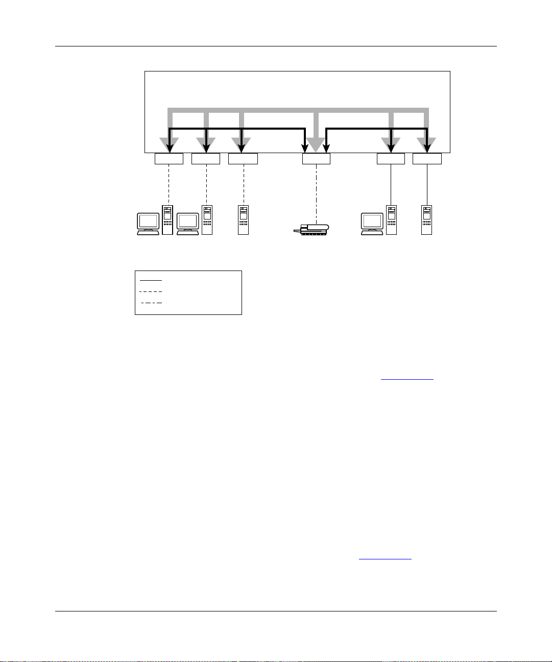
Introduction to the BayStack 410-24T Switch
S1
VLAN 3
VLAN 2 VLAN 1
Port 2
PVID = 2 PVID = 3
V2 V2 V2 V1 V2
Key
Port 4 Port 10 Port 8
VLAN 1 (PVID = 1)
VLAN 2 (PVID = 2)
VLAN 3 (PVID = 3)
Port 11Port 6
PVID = 1
V3
BS41024A
Figure 1-25. VLAN Broadcast Domains Within the Switch
The broadcast domain for each of the VLANs shown in Figure 1-25 is created by
configuring VLAN port memberships for each VLAN and then configuring each
of the ports with the appropriate PVID/VLAN association:
• Ports 8, 6, and 11 are untagged members of VLAN 1.
The PVID/VLAN association for ports 6 and 11 is: PVID = 1.
309985-B Rev 00
• Ports 2, 4, 10, and 8 are untagged members of VLAN 2.
The PVID/VLAN association for ports 2, 4, and 10 is: PVID = 2.
• Ports 2, 4, 10, 8, 6, and 11 are untagged members of VLAN 3.
The PVID/VLAN association for por t 8 is: PVID = 3.
The following steps show how to use the VLAN configuration screens to
configure the VLAN 3 broadcast domain shown in Figure 1 -25
.
1-45
Page 74

Using the BayStack 410-24T 10BASE-T Switch
To configure the VLAN port membership for VLAN 1:
1.
Select Switch Configuration from the BayStack 410-24T switch Main
Menu (or press w).
2.
From the Switch Configuration Menu, select VLAN Configuration (or
press v).
3.
From the VLAN Configuration Menu select VLAN Configuration (or
press v).
The default VLAN Configuration screen opens (Figure 1-26
VLAN Configuration
Create VLAN: [ 1 ] VLAN Type: [ Port-Based ]
Delete VLAN: [ ] Protocol Id (PID): [ None ]
VLAN Name: [ VLAN #1 ] User-Defined PID: [ 0x0000 ]
Management VLAN: [ Yes ] VLAN State: [ Active ]
Port Membership
1-6 7-12
------ ------
Unit #1 UUUUUU UUUUUU
KEY: T = Tagged Port Member, U = Untagged Port Member, - = Not a Member of VLAN
Use space bar to display choices, press <Return> or <Enter> to select choice.
Press Ctrl-R to return to previous menu. Press Ctrl-C to return to Main Menu.
):
Figure 1-26. Default VLAN Configuration Screen Example
The VLAN Configuration screen settings shown in Figure 1-26 are default
settings with all switch ports classified as untagged members of VLAN 1.
Figure 1-27
shows the VLAN Configuration screen after it is configured to
support the VLAN 3 broadcast domain shown in Figure 1-25
optional).
1-46
(VLAN Name is
309985-B Rev 00
Page 75

Introduction to the BayStack 410-24T Switch
Ports 2, 4, 6, 8, 10, and 11 are now untagged members of VLAN 3 as shown in
Figure 1-25
VLAN Configuration
Create VLAN: [ 3 ] VLAN Type: [ Port-Based ]
Delete VLAN: [ ] Protocol Id (PID): [ None ]
VLAN Name: [ Mary's VLAN ] User-Defined PID: [ 0x0000 ]
Management VLAN: [ Yes ] VLAN State: [ Active ]
Port Membership
1-6 7-12
------ ------
Unit #1 -U-U-U -U-UU-
on page 1-45.
KEY: T = Tagged Port Member, U = Untagged Port Member, - = Not a Member of VLAN
Use space bar to display choices, press <Return> or <Enter> to select choice.
Press Ctrl-R to return to previous menu. Press Ctrl-C to return to Main Menu.
Figure 1-27. VLAN Configuration Screen Example
To configure the PVID (por t VLAN identi fier ) for Port 8:
1.
From the VLAN Configuration screen, press [Ctrl]-R to return to the
VLAN Configuration Menu.
2.
From the VLAN Configuration Menu, select VLAN Port Configuration
(or press c).
The default VLAN Port Configuration screen opens (Figure 1-28
The VLAN Port Configuration screen settings shown in Figure 1-28
).
are default
settings.
309985-B Rev 00
1-47
Page 76

Using the BayStack 410-24T 10BASE-T Switch
VLAN Port Configuration
Unit: [ 1 ]
Port: [ 1 ]
Filter Tagged Frames: [ No ]
Filter Untagged Frames: [ No ]
Filter Unregistered Frames: [ No ]
Port Name: [ ]
PVID: [ 1 ]
Port Priority: [ 0 ]
Tagging: [ Untagged Access ]
Use space bar to display choices, press <Return> or <Enter> to select choice.
Press Ctrl-R to return to previous menu. Press Ctrl-C to return to Main Menu.
Figure 1-28. Default VLAN Port Configuration Screen Example
Figure 1-29 shows the VLAN Port Configuration screen after it is configured to
support the PVID assignment for port 8, as shown in Figure 1-25
optional).
The PVID/VLAN association for VLAN 3 is now PVID = 3.
1-48
(Port Name is
309985-B Rev 00
Page 77

Introduction to the BayStack 410-24T Switch
VLAN Port Configuration
Unit: [ 1 ]
Port: [ 8 ]
Filter Tagged Frames: [ No ]
Filter Untagged Frames: [ No ]
Filter Unregistered Frames: [ No ]
Port Name: [ Molly's port ]
PVID: [ 3 ]
Port Priority: [ 0 ]
Tagging: [ Untagged Access ]
Use space bar to display choices, press <Return> or <Enter> to select choice.
Press Ctrl-R to return to previous menu. Press Ctrl-C to return to Main Menu.
Figure 1-29. VLAN Port Configuration Screen Example
VLAN Workgroup Summary
This section summarizes the VLAN workgroup examples discussed in the
previous sec ti ons of this chapt er.
As shown in Figure 1-30
with multiple VLANs:
• Ports 1, 6, 11, and 12 are in VLAN 1.
• Ports 2, 3, 4, 7, and 10 are in VLAN 2.
• Port 8 is in VLAN 3.
Because switch S4 does not support 802.1Q tagging, a single switch port on each
switch must be used for each VLAN (see “VLANs Spanning Multiple Untagged
Switches” on page 1-42).
309985-B Rev 00
, switch S1 (a BayStack 410-24T switch) is configured
1-49
Page 78

Using the BayStack 410-24T 10BASE-T Switch
The connection to switch S2 requires only one link because both switch S1 and
switch S2 (BayStack 410-24T switches) support 802.1Q tagging (see “VLANs
Spanning Multiple 802.1Q Tagged Switches” on page 1-41).
Non-802.1Q
tagging switch
S4
Untagged ports
(STP disabled)
BayStack 410-24T
S1
V2 V2 V1
Key
VLAN 1 (PVID=1)
VLAN 2 (PVID=2)
VLAN 3 (PVID=3)
V3
BayStack 410-24T
S2
Both ports are tagged
members of VLAN 1
and VLAN 2
V1
Non-802.1Q
tagging switch
S3
V2
BS41025A
Figure 1-30. VLAN Configuration Spanning Multiple Switches
1-50
309985-B Rev 00
Page 79

VLAN Configuration Rules
VLANs operate according to specif ic conf igu ration rule s. When creating VLANs ,
consider the following rules th at determine how the configured VLAN reacts in
any network topology:
• All ports that are involved in port mirroring must have memberships in the
same VLANs. If a port is configured for port mirroring, the port’s VLAN
membership cannot be changed.
• If a port is a trunk group member, all trunk members are added or deleted
from the VLAN.
• All ports involved in trunking and port mirroring must have the same VLAN
configuration. If a port is on a trunk with a mirroring port, the VLAN
configuration cannot be changed.
• VLANs are not dependent on rate limiting settings.
• If a port is an IGMP m ember on any VL AN, and is removed from a VLAN,
the port’s IGMP membership is also removed.
• When you add a port to a different VLAN, and it is already configured as a
static router port, the port is configured as an IGMP m ember on that specific
VLAN.
Introduction to the BayStack 410-24T Switch
309985-B Rev 00
For more information about configuring VLANs, see “VLAN Configuration
Menu” on page 3-38.
See also Ap pendix C, “Quick Steps to Features” for configuration flowcharts that
can help you use this feature.
1-51
Page 80

Using the BayStack 410-24T 10BASE-T Switch
IGMP Snooping
BayStack 410-24T switches can sense IGMP host membership reports from
attached stations and use this information to set up a dedicated path between the
requesting stati on and a local IP Multica st route r. After the pathw ay is e stablis hed,
the BayStack 410-24T switch blocks the IP Multicast stream from exiting any
other port that does not connect to another host member, thus conserving
bandwidth. The following discussion describes how BayStack 410-24T switches
provide the sam e benefit as IP Multicast routers, but in the loc al area.
Internet Group Management Protocol (IGMP), is used by IP Multicast routers to
learn about th e e xis te nce of host group membe rs on thei r di rectl y at tached s ubnets
(see RFC 2236). The IP Multicast routers get this information by broadcasting
IGMP queries and listening for IP hosts reporting their host group memberships.
This process is used to se t up a client/server relation ship betwee n an IP Multica st
source that provides the data streams and the clients that want to receive the data.
Figure 1-31
shows how IGMP is used to set up the path between the client and
server. As shown in this example, the IGMP host provides an IP Multicast stream
to designated routers which forward the IP Multicast stream on their local network
only if there is a recipient.
The client/server path is set up as follows:
1.
The designated router sends out a host membership query to the subnet and
receives host membership reports from end stations on the subnet.
2.
The designated routers then set up a path between the IP Multicast stream
source and the end stations.
3.
Periodically, the router continues to query end stations on whet her to conti nue
participation.
4.
As long as any client continues to participate, all clients, including
nonparticipating end stations on that subnet, receive the IP Multicast stream.
Note:
Although the nonparticipating end stations can filter the IP Multicast
traffic, the IP Multicast still exists on the subnet and consumes bandwidth.
IP Multicast can be optimized in a LAN by using IP Multicast filtering switches,
such as the BayStack 410-24T switch.
1-52
309985-B Rev 00
Page 81

Introduction to the BayStack 410-24T Switch
As shown in Figure 1-31, a non-IP Multicast filtering switch causes IP Multicast
traffic to be sent to all segments on the local subnet.
Host
Membership
IGMP
Host
Query
Designated
router #1
Multicast stream
Internet
Non-multicast
filtering switch
Host
Membership
Query
Designated
router #2
Host
Membership
Report
Non-multicast
filtering switch
Figure 1-31. IP Multicast Propagation With IGMP Routing
The BayStack 410-24T switch can automatically set up IP Multicast filters so the
IP Multicast traffic is only directed to the participating end nodes (see
Figure 1-32
In Figure 1-32
).
, switches S1 to S4 represent a LAN connected to a IP Multicast
router. The router periodically sends Host Membership Queries to the LAN and
listens for a response from end stations. All of the clients connected to switches
S1 to S4 are aware of the queries from the router.
309985-B Rev 00
Host
Membership
Report
1-53
Page 82

Using the BayStack 410-24T 10BASE-T Switch
One client, connected to S2, responds with a host membership report. Switch S2
intercepts the report from that port, and generates a proxy report to its upstream
neighbor, S1. Also, two clients connected to S4 respond with host membership
reports, causing S4 to intercept the reports and to generate a consolidated proxy
report to its upstream neighbor, S1.
Internet
Designated
router
Host
Membership
Report
Proxy
S1
S4
S2
Consolidated
report
Proxy
BayStack 410-24T
Switch
BayStack 410-24T
Switch
BayStack 410-24T
Switches
Host
Membership
Report
Host
Membership
Query
S3
Figure 1-32. BayStack 410-24T Switch Filtering IP Multicast Streams (1 of 2)
BS41027A
1-54
Switch S1 treats the conso lidated proxy reports fro m S2 and S4 as if they were
reports from any client connected to its ports, and generates a consolidated proxy
report to the designated router. In this way, the router receives a single
consolidated report from that entire subnet.
309985-B Rev 00
Page 83

Introduction to the BayStack 410-24T Switch
After the switches learn which ports are requesting access to the IP Multicast
stream, all other ports no t responding to t he queries are bl ocked from re ceiv ing the
IP Multicast (see Figure 1-33
Internet
S1
S2
BayStack 410-24T
Switch
).
Designated
router
Host
Membership
Query
BayStack 410-24T
Switches
S3
BayStack 410-24T
S4
Switch
Key
Multicast stream
BS41028A
Figure 1-33. BayStack 410-24T Switch Filtering IP Multicast Streams (2 of 2)
The consolidated proxy report generated by the switch remains transparent to
layer 3 of th e Internation al Organization for Standardization, Op en Systems
Interconnection (ISO/OSI) model. (The switch IP address and MAC address are
not part of proxy report generation.) The last reporting IGMP group member in
each VLAN represents all of the hosts in that VLAN and IGMP group.
309985-B Rev 00
1-55
Page 84

Using the BayStack 410-24T 10BASE-T Switch
IGMP Snooping Configuration Rules
The IGMP snooping feature operates according to specific configuration rules.
When configuring your switch for IGMP snooping, consider the following rules
that determine how the configuration reacts in any network topology:
• A port that is configured for port mirroring cannot be configured as a static
router port.
• If a MultiLink Trunk member is configured as a static router port, all of the
MultiLink Trunk members are configured as static router ports. Also, if a
static router port is removed, and it is a MultiLink Trunk member, all
MultiLink Trunk members are removed as static router port members,
automatically.
• Static router ports must be port members of at least one VLAN.
• If a port is configured as a static router port, it is configured as a static router
port for all VLANs on that port. The IGMP configuration is propagated
through all VLANs of that port.
• If a static router port is removed, the membership for that port is removed
from all VLANs of that port.
1-56
• The IGMP snooping feature is not STP dependent.
• The IGMP snooping feature is not rate-limiting dependent.
• The snooping field must be enabled for the proxy field to have any valid
meaning.
• Static router ports are configured per VLAN and per IGMP Version.
Note:
Because IGMP snooping is set up per VLAN, all IGMP changes are
implemented according to the VLAN configuration for the specified ports.
For more information about using the IGMP snooping feature, see “IGMP
Configuration Me nu” on page 3-71.
See also Ap pendix C, “Quick Steps to Features” for configuration flowcharts that
can help you use this feature.
309985-B Rev 00
Page 85

IEEE 802.1p Priorit izing
You can use the VLAN Configuration screens to prioritize the order in which the
switch forwards packets, on a per-port basis. For example, if messages from a
specific segment are crucial to your operation, you can set the switch port
connected to that s egment to a higher priorit y le ve l (b y defaul t, al l switch port s are
set to Low priority). Untagged packets received by the switch on that port are
tagged according to the priority level you assign to the port (see Figure 1-34
Before
Introduction to the BayStack 410-24T Switch
).
CRC
Data
SA
DA
PVID = 2
Priority = 6
Port 1
802.1Q Switch
Port 4
Port 6 Port 7 Port 8
Untagged member
of VLAN 2
Outgoing
untagged packet
(unchanged)
Port configuration
parameters
Port 2 Port 3
transmit
CRC
Data
SA
DA
Figure 1-34. Prioritizing Packets
Port 5
queue
High
Low
Tagged member
of VLAN 2 (Port 5)
Port 5
(*Recalculated)
Key
Priority
CFI
VID
DASADataCRC* Tag
8100 CFI
16 bits 3 bits 1 bit 12 bits
After
- User_priority
- Canonical format indicator
- VLAN identifier
VID = 2Priority = 6
BS41029A
309985-B Rev 00
The newly tagged frame is read within the switch and sent to the port’s high or l o w
transmit queue for disposition (see Figure 1-35
shown in Figure 1-35
applies to all ports on the BayStack 410-24T switch.
). The port transmit queue example
1-57
Page 86

Using the BayStack 410-24T 10BASE-T Switch
Port 5
User priority
(6)
Port
transmit
queue
Traffic
class
7
6
High
5
4
3
2
Low
1
0
High priority
packet
BS41030A
Figure 1-35. Port Transmit Queue
As shown in Figure 1-35, the switch provides two transmission queues, a High
transmission queue and a Low transmission queue, for any given port. Frames are
assigned to one of these queues on the basis of user_priority using a traffic class
table. This table is managed by using the Traffic Class Configuration screen
(Figure 1-36
). The table indicates the corresponding traffic class that is assigned
to the frame, for each possible user_priority value. If the frame leaves the switch
formatted as a tagged packet, the traffic class assigned to the frame is c arried
forward to the next 802.1p capable switch. This allows the packet to carry the
assigned traffic class priority through the network until it reaches its destination.
1-58
The following steps show how to use the Traffic Class Configuration screen to
configure the port priority level shown in the example Figure 1-34
.
For more information about using the Traffic Class Configuration screen, see
“VLAN Configuration” on page 3-40.
309985-B Rev 00
Page 87

Introduction to the BayStack 410-24T Switch
To configure the port priority level, follow these steps:
1.
Determine the priority level you want to assign to the switch port.
User priority levels are assigned default settings in all BayStack 410-24T
switches. The range is from 0 to 7. The traffic class table can be modified,
therefore, view the settings shown in the Traffic Class Configuration screen
before setting the port priority in the VLAN Port Configuration screen.
2.
Select Switch Configuration from the BayStack 410-24T switch Main
Menu (or press w).
3.
From the Switch Configuration Menu, select VLAN Configuration (or
press v).
4.
From the VLAN Configuration Menu, select Traffic Class Configuration
(or press t).
The Traffic Class Configuration screen opens (Figure 1-36
Traffic Class Configuration
User Priority Traffic Class
------------- ------------ Priority 0: [ Low ]
Priority 1: [ Low ]
Priority 2: [ Low ]
Priority 3: [ Low ]
Priority 4: [ Low ]
Priority 5: [ Low ]
Priority 6: [ Low ]
Priority 7: [ Low ]
Use space bar to display choices, press <Return> or <Enter> to select choice.
Press Ctrl-R to return to previous menu. Press Ctrl-C to return to Main Menu.
).
Figure 1-36. Default Traffic Class Configuration Screen Example
309985-B Rev 00
1-59
Page 88

Using the BayStack 410-24T 10BASE-T Switch
5.
Select a priority level from the range shown in the Traffic Class
Configuration scr een (or modify the Traffic Class paramet ers to sui t y our
needs).
6.
Assign the priority level to ports using the VLAN Port Configuration
screen:
a.
Press [Ctrl]-R to return to the VLAN Configuration Menu.
b.
From the VLAN Configuration Menu, select VLAN Port
Configuration (or press c).
The VLAN Port Configuration screen opens (Figure 1-37
Figure 1-37
Figure 1-34
VLAN Port Configuration
Port: [ 4 ]
Filter Tagged Frames: [ No ]
Filter Untagged Frames: [ No ]
Filter Unregistered Frames: [ No ]
Port Name: [ Luke’s port ]
PVID: [ 2 ]
Port Priority: [ 6 ]
Tagging: [ Untagged Access ]
Use space bar to display choices, press <Return> or <Enter> to select choice.
Press Ctrl-R to return to previous menu. Press Ctrl-C to return to Main Menu.
shows the VLAN Port Configuration screen setup for port 4 in
on page 1-57.
).
Figure 1-37. Setting Port Priority Example
For more information about using this feature, see “VLAN Configuration Menu”
on page 3-38.
1-60
309985-B Rev 00
Page 89

MultiLink Trunks
A MultiLink T runk (MLT)1 allows y ou to group up to four switch ports together to
form a link to another switch or server, thus increasing aggregate throughput of
the interconnection between the devices (up to 800 Mb/s in full-duplex mode with
optional 100BASE-T/F MDAs installed). You can configure up to six MultiLink
Trunks. The MLT members can reside on a single unit or on multipl e uni ts with in
the same stack configuration as a distributed trunk. MLT software detects
misconfigured ( or brok en) tru nk links a nd redire cts traffic on the misconf i gured or
broken trunk link to other trunk members within that MLT.
You can use the MultiLink Trunk Configuration screen to create switch-to-switch
and switch-to-server MLT links (see Figure 1-38
Introduction to the BayStack 410-24T Switch
and Figure 1-39).
Figure 1-38
and S3.
S2
shows two trunks (T1 and T2) connecting switch S1 to switches S2
S1
F
F
S3
T1
T2
BS41031A
Figure 1-38. Switch-to-Switch Trunk Configuration Example
1
In this guide, the terms “trunk” and “MLT” are used interchangeably to indicate a MultiLink Trunk.
309985-B Rev 00
1-61
Page 90

Using the BayStack 410-24T 10BASE-T Switch
Each of the trunks shown in Figure 1-38 can be configured with up to four switch
ports to provi de maximum aggre gate bandwid th through each t runk, in full- duplex
mode. As shown in this example, when traffic between switch-to-switch
connections approaches single port bandwidth limitations, creating a MultiLink
Trunk can supply the additional bandwidth required to improve the performance.
Figure 1-39
shows a typica l switch-t o-ser v er tru nk configuration. In this example,
file server FS1 uses dual MAC addresses, using one MAC address for each
network interface controller (NIC). For this reason, FS1 does not require a trunk
assignment. FS2 is a single MAC server (with a four-port NIC) and is set up as
trunk configuration T1.
FS1
S1
FS2
T1
BS41032A
Figure 1-39. Switch-to-Server Trunk Configuration Example
Client/Server Configuration Using MultiLink Trunks
Figure 1-40 shows an example of how MultiLink Trunking can be used in a
client/server configuration. In t his example, both server s a re connected directly to
switch S1. FS2 is connected through a trunk configuration (T1). The
switch-to-switch connections are through trunks (T2, T3, T4, and T5).
1-62
309985-B Rev 00
Page 91

A
Introduction to the BayStack 410-24T Switch
Clients accessing data from the servers (FS1 and FS2) are provided with
maximized bandwidth through trunks T1, T2, T3, T4, and T5. Trunk members
(the ports making up each trunk) do not have to be consecutive switch ports; they
can be selected randomly, as shown by T5.
With spanning tree enabled, one of the trunks (T2 or T3) acts as a redundant
(backup) trunk to switch S2. With spanning tree disabled, trunks T2 and T3 must
be configured into separate VLANs for this configuration to function properly
(see “I
EEE 802.1Q VLAN Workgroups” on page 1-36).
FS1
S1
F
F
T2
T3 T4
S2
S3
Figure 1-40. Client/Server Configuration Example
S4
FS2
T1
T5
BS41033
309985-B Rev 00
The trunk configuration screens for switches S1 to S4 are shown in “Trunk
Configuration Scr een Exampl es” followin g this section. For detailed information
about configuring trunks, see “MultiLink Trunk Configuration” on page 3-57.
1-63
Page 92

Using the BayStack 410-24T 10BASE-T Switch
Trunk Configuration Screen Examples
This section sho ws e xamples o f the MultiLi nk T run k conf igurati on screens for the
client/server configuration example shown in Figure 1-40
screens show how you could set up the trunk configuration screens for switches
S1 to S4. See “Spanning Tree Considerations for MultiLink Trunks
page 1-76
information.
Trunk Configuration Screen for Switch S1
Switch S1 is set up with five trunk configurations: T1, T2, T3, T4, and T5.
Setting up the Tr unk Configuration for S1:
To set up the trunk configuration, choose MultiLink Trunk Configuration
(or press t) from the MultiLink Trunk Configuration Menu screen (Figure 1-41
MultiLink Trunk Configuration Menu
, and “MultiLink Trunk Configuration” on page 3-57 for more
on page 1-63. T he
” on
).
MultiLink Trunk Configuration...
MultiLink Trunk Utilization...
Return to Switch Configuration Menu
Use arrow keys to highlight option, press <Return> or <Enter> to select option.
Press Ctrl-R to return to previous menu. Press Ctrl-C to return to Main Menu.
Figure 1-41. Choosing the MultiLink Trunk Configuration Screen
1-64
309985-B Rev 00
Page 93

Introduction to the BayStack 410-24T Switch
The MultiLink Trunk Configuration screen opens (Figure 1-42).
MultiLink Trunk Configuration
Trunk Trunk Members (Unit/Port) STP Learning Trunk Mode Trunk Status
----- ------------------------------- ------------ --------------- ----------- 1 [ /15 ][ /17 ][ /19 ][ /21 ] [ Normal ] Basic [ Enabled ]
2 [ /25 ][ /26 ][ / ][ / ] [ Normal ] Basic [ Enabled ]
3 [ /2 ][ /4 ][ / ][ / ] [ Normal ] Basic [ Enabled ]
4 [ /14 ][ /16 ][ / ][ / ] [ Normal ] Basic [ Enabled ]
5 [ /22 ][ /24 ][ / ][ / ] [ Fast ] Basic [ Enabled ]
6 [ / ][ / ][ / ][ / ] [ Normal ] Basic [ Disabled ]
Trunk Trunk Name
----- ----------------- 1 [ S1:T1 to FS2 ]
2 [ S1:T2 to S2 ]
3 [ S1:T3 to S2 ]
4 [ S1:T4 to S3 ]
5 [ S1:T5 to S4 ]
6 [ Trunk #6 ]
Enter text, press <Return> or <Enter> when complete.
Press Ctrl-R to return to previous menu. Press Ctrl-C to return to Main Menu.
Figure 1-42. MultiLink Trunk Configuration Screen for Switch S1
Switch S1 is configured as follows:
• Trunk (read only) indicates the trunks (1 to 6) that correspond to the switch
ports specified in the Trunk Members fields.
• Trunk Members (Unit/Port) indicates the ports that can be configured, in
each row, to create the corresponding trunk:
Note:
The Unit value (in the Unit/Port field) cannot be configured when the
switch is operating standalone. For detailed inform ation about the MultiLin k
Trunk Configuration screen fields, see “MultiLink Trunk Con figuration” on
page 3-57.
-- Ports 15, 17, 19, and 21 are assigned as trunk members of trunk 1.
-- Ports 25 and 26 are assigned as trunk members of trunk 2.
309985-B Rev 00
1-65
Page 94

Using the BayStack 410-24T 10BASE-T Switch
-- Ports 2 and 4 are assigned as trunk members of trunk 3.
-- Ports 14 and 16 are assigned as trunk members of trunk 4.
-- Ports 22 and 24 are assigned as trunk members of trunk 5.
• STP Learning indicates the spa nni ng tr ee par tici patio n sett ing f or ea ch of the
trunks:
-- Trunks 1 through 4 are enabled for Normal STP Learning.
-- Trunk 5 is enabled for Fast STP Learning.
• Trunk Mode (read only) indicates the Trunk Mode for each of the trunks:
The Trunk Mode field values for trunks 1 to 5 are set to Basic. Source MAC
addresses are statically assigned to specific trunk members for flooding and
forwarding. This allows the switch to stabilize and distribute the data streams
of source addresses across the trunk members.
• Trunk Status indicates the Trunk Status for each of the trunks. When set to
Enabled, th e configuration settings for th at specific trunk are activated.
• Trunk Name indicates optional fields for assigning names to the
corresponding configured trunks.
1-66
The names chosen for this example provide meaningful information to the
user of this switch (for example, S1:T1 to FS2 indicates that Trunk 1, in
switch S1, connects to File Server 2).
309985-B Rev 00
Page 95

Introduction to the BayStack 410-24T Switch
Trunk Configuration Screen for Switch S2
As shown in Figure 1-40
on page 1-63, switch S2 is set up with two trunk
configurations (T2 and T3). Both trunks connect directly to switch S1. As in the
previous scre en e xampl es, to s et up a t runk c onfiguration choose Mult iLink T r unk
Configuration from the MultiLink Trunk Configuration Menu screen.
Figure 1-43
MultiLink Trunk Configuration
Trunk Trunk Members (Unit/Port) STP Learning Trunk Mode Trunk Status
----- ------------------------------- ------------ --------------- ----------- 1 [ /25 ][ /26 ][ / ][ / ] [ Normal ] Basic [ Enabled ]
2 [ /1 ][ /3 ][ / ][ / ] [ Normal ] Basic [ Enabled ]
3 [ / ][ / ][ / ][ / ] [ Normal ] Basic [ Disabled ]
4 [ / ][ / ][ / ][ / ] [ Normal ] Basic [ Disabled ]
5 [ / ][ / ][ / ][ / ] [ Normal ] Basic [ Disabled ]
6 [ / ][ / ][ / ][ / ] [ Normal ] Basic [ Disabled ]
Trunk Trunk Name
----- ----------------- 1 [ S2:T2 to S1 ]
2 [ S2:T3 to S1 ]
3 [ Trunk #3 ]
4 [ Trunk #4 ]
5 [ Trunk #5 ]
6 [ Trunk #6 ]
shows the MultiLink Trunk Configuration screen for switch S2.
Enter text, press <Return> or <Enter> when complete.
Press Ctrl-R to return to previous menu. Press Ctrl-C to return to Main Menu.
Figure 1-43. MultiLink Trunk Configuration Screen for Switch S2
Switch S2 is configured as follows:
• Trunk (read only) indicates the trunks (1 to 6) that corresponds to the switch
ports specified in the Trunk Members fields.
• Trunk Members (Unit/Port) indicates the ports that can be configured, in
each row, to create the corresponding trunk:
-- Ports 25 and 26 are assigned as trunk members of trunk 1.
-- Ports 1 and 3 are assigned as trunk members of trunk 2.
309985-B Rev 00
1-67
Page 96

Using the BayStack 410-24T 10BASE-T Switch
• STP Learning indicates the spa nni ng tr ee par tici patio n sett ing f or ea ch of the
trunks:
Trunk 1 and 2 are enabled for Normal STP Learning.
• Trunk Mode (read only) indicates the Trunk Mode for each of the trunks:
The Trun k Mode field values for tr unks 1 and 2 are set to Basic. Source MAC
addresses are statically assigned to specific trunk members for flooding and
forwarding. This allows the switch to stabilize and distribute the data streams
of source addresses across the trunk members.
• Trunk Status indicates the Trunk Status for each of the trunks. When set to
Enabled, th e configuration settings for th at specific trunk are activated.
• Trunk Name indicates optional fields for assigning names to the
corresponding configured trunks.
The names chosen for this example provide meaningful information to the
user of this switch (for example, S2:T2 to S1 i ndi cates that Trunk 1, i n swi tc h
S2, connects to Switch 1).
1-68
309985-B Rev 00
Page 97

Introduction to the BayStack 410-24T Switch
Trunk Configuration Screen for Switch S3
As shown in Figure 1-40
on page 1-63, switch S3 is set up with one trunk
configuration (T4). This trunk connects directly to switch S1.
As in the previous screen examples, to set up an inter-switch trunk configuration
choose MultiLink Trunk Configuration from the MultiLink Trunk Configuration
Menu screen.
Figure 1-44
MultiLink Trunk Configuration
Trunk Trunk Members (Unit/Port) STP Learning Trunk Mode Trunk Status
----- ------------------------------- ------------ --------------- ----------- 1 [ /1 ][ /3 ][ / ][ / ] [ Normal ] Basic [ Enabled ]
2 [ / ][ / ][ / ][ / ] [ Normal ] Basic [ Disabled ]
3 [ / ][ / ][ / ][ / ] [ Normal ] Basic [ Disabled ]
4 [ / ][ / ][ / ][ / ] [ Normal ] Basic [ Disabled ]
5 [ / ][ / ][ / ][ / ] [ Normal ] Basic [ Disabled ]
6 [ / ][ / ][ / ][ / ] [ Normal ] Basic [ Disabled ]
Trunk Trunk Name
----- ----------------- 1 [ S3:T4 to S1 ]
2 [ Trunk #2 ]
3 [ Trunk #3 ]
4 [ Trunk #4 ]
5 [ Trunk #5 ]
6 [ Trunk #6 ]
shows the MultiLink Trunk Configuration screen for switch S3.
Enter text, press <Return> or <Enter> when complete.
Press Ctrl-R to return to previous menu. Press Ctrl-C to return to Main Menu.
Figure 1-44. MultiLink Trunk Configuration Screen for Switch S3
Switch S3 is configured as follows:
• Trunk (read only) indicates the trunk (1 to 6) that corresponds to the switch
ports specified in the Trunk Members fields.
• Trunk Members (Unit/Port) indicates the ports that can be configured, in
each row, to create the corresponding trunk:
Ports 1 and 3 are assigned as trunk members of trunk 1.
309985-B Rev 00
1-69
Page 98

Using the BayStack 410-24T 10BASE-T Switch
• STP Learning indicates the spa nni ng tr ee par tici patio n sett ing f or ea ch of the
trunks:
Trunk 1 is enabled for Normal STP Learning.
• Trunk Mode (read only) indicates the Trunk Mode for each of the trunks:
The Trun k Mode f ield value for trunk 1 is set to Bas ic. Source MA C add resses
are statically ass igned t o speci f i c tru nk members fo r flo oding an d forw ardi ng.
This allows the switch to stabilize and distribute the data streams of source
addresses across the trunk members.
• Trunk Status indicates the Trunk Status for each of the trunks. When set to
Enabled, th e configuration settings for th at specific trunk are activated.
• Trunk Name indicates optional fields for assigning names to the
corresponding configured trunks.
The names chosen for this example provide meaningful information to the
user of this switch (for example, S3:T4 to S1 i ndi cates that Trunk 1, i n swi tc h
S3, connects to Switch 1).
1-70
309985-B Rev 00
Page 99

Introduction to the BayStack 410-24T Switch
Trunk Configuration Screen for Switch S4
As shown in Figure 1-40
, switch S4 is set up with one trunk configuration (T5).
This trunk connects directly to switch S1.
As in the previous screen examples, to set up a trunk configuration choose
MultiLink Trunk Configuration from the MultiLink Trunk Configuration Menu
screen.
Figure 1-45
MultiLink Trunk Configuration
Trunk Trunk Members (Unit/Port) STP Learning Trunk Mode Trunk Status
----- ------------------------------- ------------ --------------- ----------- 1 [ /5 ][ /11 ][ / ][ / ] [ Normal ] Basic [ Enabled ]
2 [ / ][ / ][ / ][ / ] [ Normal ] Basic [ Disabled ]
3 [ / ][ / ][ / ][ / ] [ Normal ] Basic [ Disabled ]
4 [ / ][ / ][ / ][ / ] [ Normal ] Basic [ Disabled ]
5 [ / ][ / ][ / ][ / ] [ Normal ] Basic [ Disabled ]
6 [ / ][ / ][ / ][ / ] [ Normal ] Basic [ Disabled ]
Trunk Trunk Name
----- ----------------- 1 [ S4:T5 to S1 ]
2 [ Trunk #2 ]
3 [ Trunk #3 ]
4 [ Trunk #4 ]
5 [ Trunk #5 ]
6 [ Trunk #6 ]
shows the MultiLink Trunk Configuration screen for switch S4.
Enter text, press <Return> or <Enter> when complete.
Press Ctrl-R to return to previous menu. Press Ctrl-C to return to Main Menu.
Figure 1-45. MultiLink Trunk Configuration Screen for Switch S4
309985-B Rev 00
1-71
Page 100

Using the BayStack 410-24T 10BASE-T Switch
Switch S4 is configured as follows:
• Trunk (read only) indicates the trunk (1 to 6) that corresponds to the switch
ports specified in the Trunk Members fields.
• Trunk Members (Unit/Port) indicates the ports that can be configured, in
each row, to create the corresponding trunk:
Ports 5 and 11 are assigned as trunk members of trunk T1.
• STP Learning indicates the spa nning t ree parti cipat ion s ettin g for ea ch of the
trunks:
Trunk 1 is enabled for Normal STP Learning.
• Trunk Mode (read only) indicates the Trunk Mode for each of the trunks:
The Trun k Mode f ield value for trunk 1 is set to Bas ic. Source MA C add resses
are statically ass igned t o speci f i c tru nk members f or flo oding an d forw ardi ng.
This allows the switch to stabilize and distribute the data streams of source
addresses across the trunk members.
• Trunk Status indicates the Trunk Status for each of the tr unks . Wh en i t i s se t
to Enabled, the configuration settings for that specific tru nk are activated.
• Trunk Name indicates optional fields for assigning names to the
corresponding configured trunks.
1-72
The names chosen for this example provide meaningful information to the
user (for example, S4:T5 to S1 indicates that Trunk 1, in switch S4, connects
to Switch 1).
309985-B Rev 00
 Loading...