


 Loading...
Using the BayStack 350
10/100/1000 Series
Switch
Part No. 304376-B Rev 00
January 1999

4401 Great America Parkway |
8 Federal Street |
Santa Clara, CA 95054 |
Billerica, MA 01821 |
|
|
Copyright © 1999 Bay Networks, Inc.
All rights reserved. Printed in the USA. January 1999.
The information in this document is subject to change without notice. The statements, configurations, technical data, and recommendations in this document are believed to be accurate and reliable, but are presented without express or implied warranty. Users must take full responsibility for their applications of any products specified in this document. The information in this document is proprietary to Bay Networks, Inc.
Trademarks
Optivity and Bay Networks are registered trademarks and Accelar, BayStack, EZ LAN, Optivity Campus, Optivity Enterprise, StackProbe, and the Bay Networks logo are trademarks of Bay Networks, Inc.
All other trademarks and registered trademarks are the property of their respective owners.
Statement of Conditions
In the interest of improving internal design, operational function, and/or reliability, Bay Networks, Inc. reserves the right to make changes to the products described in this document without notice.
Bay Networks, Inc. does not assume any liability that may occur due to the use or application of the product(s) or circuit layout(s) described herein.
USA Requirements Only
Federal Communications Commission (FCC) Compliance Notice: Radio Frequency Notice
Note: This equipment has been tested and found to comply with the limits for a Class A digital device, pursuant to Part 15 of the FCC rules. These limits are designed to provide reasonable protection against harmful interference when the equipment is operated in a commercial environment. This equipment generates, uses, and can radiate radio frequency energy. If it is not installed and used in accordance with the instruction manual, it may cause harmful interference to radio communications. Operation of this equipment in a residential area is likely to cause harmful interference, in which case users will be required to take whatever measures may be necessary to correct the interference at their own expense.
European Requirements Only
EN 55 022 Statement
This is to certify that the Bay Networks BayStack 350 10/100 Autosense Switch is shielded against the generation of radio interference in accordance with the application of Council Directive 89/336/EEC, Article 4a. Conformity is declared by the application of EN 55 022 Class A (CISPR 22).
Warning: This is a Class A product. In a domestic environment, this product may cause radio interference, in which case, the user may be required to take appropriate measures.
EC Declaration of Conformity
This product conforms to the provisions of Council Directive 89/336/EEC and 73/23/EEC. The Declaration of Conformity is available on the Bay Networks World Wide Web site at www.baynetworks.com.
ii |
304376-B Rev 00 |

Japan/Nippon Requirements Only
Voluntary Control Council for Interference (VCCI) Statement
Voluntary Control Council for Interference (VCCI) Statement
This is a Class A product based on the standard of the Voluntary Control Council for Interference by Information Technology Equipment (VCCI). If this equipment is used in a domestic environment, radio disturbance may arise. When such trouble occurs, the user may be required to take corrective actions.
Canada Requirements Only
Canadian Department of Communications Radio Interference Regulations
This digital apparatus (BayStack 350 10/100 Autosense Switch) does not exceed the Class A limits for radio-noise emissions from digital apparatus as set out in the Radio Interference Regulations of the Canadian Department of Communications.
Règlement sur le brouillage radioélectrique du ministère des Communications
Cet appareil numérique (BayStack 350 10/100 Autosense Switch) respecte les limites de bruits radioélectriques visant les appareils numériques de classe A prescrites dans le Règlement sur le brouillage radioélectrique du ministère des Communications du Canada.
Bay Networks, Inc. Software License Agreement
NOTICE: Please carefully read this license agreement before copying or using the accompanying software or installing the hardware unit with pre-enabled software (each of which is referred to as “Software” in this Agreement). BY COPYING OR USING THE SOFTWARE, YOU ACCEPT ALL OF THE TERMS AND CONDITIONS OF THIS LICENSE AGREEMENT. THE TERMS EXPRESSED IN THIS AGREEMENT ARE THE ONLY TERMS UNDER WHICH BAY NETWORKS WILL PERMIT YOU TO USE THE SOFTWARE. If you do not accept these terms and conditions, return the product, unused and in the original shipping container, within 30 days of purchase to obtain a credit for the full purchase price.
1. License Grant. Bay Networks, Inc. (“Bay Networks”) grants the end user of the Software (“Licensee”) a personal, nonexclusive, nontransferable license: a) to use the Software either on a single computer or, if applicable, on a single authorized device identified by host ID, for which it was originally acquired; b) to copy the Software solely for backup purposes in support of authorized use of the Software; and c) to use and copy the associated user manual solely in support of authorized use of the Software by Licensee. This license applies to the Software only and does not extend to Bay Networks Agent software or other Bay Networks software products. Bay Networks Agent software or other Bay Networks software products are licensed for use under the terms of the applicable Bay Networks, Inc. Software License Agreement that accompanies such software and upon payment by the end user of the applicable license fees for such software.
304376-B Rev 00 |
iii |

2.Restrictions on use; reservation of rights. The Software and user manuals are protected under copyright laws. Bay Networks and/or its licensors retain all title and ownership in both the Software and user manuals, including any revisions made by Bay Networks or its licensors. The copyright notice must be reproduced and included with any copy of any portion of the Software or user manuals. Licensee may not modify, translate, decompile, disassemble, use for any competitive analysis, reverse engineer, distribute, or create derivative works from the Software or user manuals or any copy, in whole or in part. Except as expressly provided in this Agreement, Licensee may not copy or transfer the Software or user manuals, in whole or in part. The Software and user manuals embody Bay Networks’ and its licensors’ confidential and proprietary intellectual property. Licensee shall not sublicense, assign, or otherwise disclose to any third party the Software, or any information about the operation, design, performance, or implementation of the Software and user manuals that is confidential to Bay Networks and its licensors; however, Licensee may grant permission to its consultants, subcontractors, and agents to use the Software at Licensee’s facility, provided they have agreed to use the Software only in accordance with the terms of this license.
3.Limited warranty. Bay Networks warrants each item of Software, as delivered by Bay Networks and properly installed and operated on Bay Networks hardware or other equipment it is originally licensed for, to function substantially as described in its accompanying user manual during its warranty period, which begins on the date Software is first shipped to Licensee. If any item of Software fails to so function during its warranty period, as the sole remedy Bay Networks will at its discretion provide a suitable fix, patch, or workaround for the problem that may be included in a future Software release. Bay Networks further warrants to Licensee that the media on which the Software is provided will be free from defects in materials and workmanship under normal use for a period of 90 days from the date Software is first shipped to Licensee. Bay Networks will replace defective media at no charge if it is returned to Bay Networks during the warranty period along with proof of the date of shipment. This warranty does not apply if the media has been damaged as a result of accident, misuse, or abuse.
The Licensee assumes all responsibility for selection of the Software to achieve Licensee’s intended results and for the installation, use, and results obtained from the Software. Bay Networks does not warrant a) that the functions contained in the software will meet the Licensee’s requirements, b) that the Software will operate in the hardware or software combinations that the Licensee may select, c) that the operation of the Software will be uninterrupted or error free, or d) that all defects in the operation of the Software will be corrected. Bay Networks is not obligated to remedy any Software defect that cannot be reproduced with the latest Software release. These warranties do not apply to the Software if it has been (i) altered, except by Bay Networks or in accordance with its instructions; (ii) used in conjunction with another vendor’s product, resulting in the defect; or (iii) damaged by improper environment, abuse, misuse, accident, or negligence.
THE FOREGOING WARRANTIES AND LIMITATIONS ARE EXCLUSIVE REMEDIES AND ARE IN LIEU OF ALL OTHER WARRANTIES EXPRESS OR IMPLIED, INCLUDING WITHOUT LIMITATION ANY WARRANTY OF MERCHANTABILITY OR FITNESS FOR A PARTICULAR PURPOSE. Licensee is responsible for the security of its own data and information and for maintaining adequate procedures apart from the Software to reconstruct lost or altered files, data, or programs.
4.Limitation of liability. IN NO EVENT WILL BAY NETWORKS OR ITS LICENSORS BE LIABLE FOR ANY COST OF SUBSTITUTE PROCUREMENT; SPECIAL, INDIRECT, INCIDENTAL, OR CONSEQUENTIAL DAMAGES; OR ANY DAMAGES RESULTING FROM INACCURATE OR LOST DATA OR LOSS OF USE OR PROFITS ARISING OUT OF OR IN CONNECTION WITH THE PERFORMANCE OF THE SOFTWARE, EVEN IF BAY NETWORKS HAS BEEN ADVISED OF THE POSSIBILITY OF SUCH DAMAGES. IN NO EVENT SHALL THE LIABILITY OF BAY NETWORKS RELATING TO THE SOFTWARE OR THIS AGREEMENT EXCEED THE PRICE PAID TO BAY NETWORKS FOR THE SOFTWARE LICENSE.
5.Government Licensees. This provision applies to all Software and documentation acquired directly or indirectly by or on behalf of the United States Government. The Software and documentation are commercial products, licensed on the open market at market prices, and were developed entirely at private expense and without the use of any U.S. Government funds. The license to the U.S. Government is granted only with restricted rights, and use, duplication, or disclosure by the U.S. Government is subject to the restrictions set forth in subparagraph (c)(1) of the Commercial Computer Software––Restricted Rights clause of FAR 52.227-19 and the limitations set out in this license for civilian agencies, and subparagraph (c)(1)(ii) of the Rights in Technical Data and Computer Software clause of DFARS 252.227-7013, for agencies of the Department of Defense or their successors, whichever is applicable.
iv |
304376-B Rev 00 |

6.Use of Software in the European Community. This provision applies to all Software acquired for use within the European Community. If Licensee uses the Software within a country in the European Community, the Software Directive enacted by the Council of European Communities Directive dated 14 May, 1991, will apply to the examination of the Software to facilitate interoperability. Licensee agrees to notify Bay Networks of any such intended examination of the Software and may procure support and assistance from Bay Networks.
7.Term and termination. This license is effective until terminated; however, all of the restrictions with respect to Bay Networks’ copyright in the Software and user manuals will cease being effective at the date of expiration of the Bay Networks copyright; those restrictions relating to use and disclosure of Bay Networks’ confidential information shall continue in effect. Licensee may terminate this license at any time. The license will automatically terminate if Licensee fails to comply with any of the terms and conditions of the license. Upon termination for any reason, Licensee will immediately destroy or return to Bay Networks the Software, user manuals, and all copies. Bay Networks is not liable to Licensee for damages in any form solely by reason of the termination of this license.
8.Export and Re-export. Licensee agrees not to export, directly or indirectly, the Software or related technical data or information without first obtaining any required export licenses or other governmental approvals. Without limiting the foregoing, Licensee, on behalf of itself and its subsidiaries and affiliates, agrees that it will not, without first obtaining all export licenses and approvals required by the U.S. Government: (i) export, re-export, transfer, or divert any such Software or technical data, or any direct product thereof, to any country to which such exports or re-exports are restricted or embargoed under United States export control laws and regulations, or to any national or resident of such restricted or embargoed countries; or (ii) provide the Software or related technical data or information to any military end user or for any military end use, including the design, development, or production of any chemical, nuclear, or biological weapons.
9.General. If any provision of this Agreement is held to be invalid or unenforceable by a court of competent jurisdiction, the remainder of the provisions of this Agreement shall remain in full force and effect. This Agreement will be governed by the laws of the state of California.
Should you have any questions concerning this Agreement, contact Bay Networks, Inc., 4401 Great America Parkway, P.O. Box 58185, Santa Clara, California 95054-8185.
LICENSEE ACKNOWLEDGES THAT LICENSEE HAS READ THIS AGREEMENT, UNDERSTANDS IT, AND AGREES TO BE BOUND BY ITS TERMS AND CONDITIONS. LICENSEE FURTHER AGREES THAT THIS AGREEMENT IS THE ENTIRE AND EXCLUSIVE AGREEMENT BETWEEN BAY NETWORKS AND LICENSEE, WHICH SUPERSEDES ALL PRIOR ORAL AND WRITTEN AGREEMENTS AND COMMUNICATIONS BETWEEN THE PARTIES PERTAINING TO THE SUBJECT MATTER OF THIS AGREEMENT. NO DIFFERENT OR ADDITIONAL TERMS WILL BE ENFORCEABLE AGAINST BAY NETWORKS UNLESS BAY NETWORKS GIVES ITS EXPRESS WRITTEN CONSENT, INCLUDING AN EXPRESS WAIVER OF THE TERMS OF THIS AGREEMENT.
304376-B Rev 00 |
v |

Contents
Preface |
|
Before You Begin ............................................................................................................. |
xix |
Organization .................................................................................................................... |
xx |
Text Conventions ............................................................................................................. |
xxi |
Acronyms ......................................................................................................................... |
xxi |
Related Publications ....................................................................................................... |
xxii |
How to Get Help ............................................................................................................ |
xxiii |
Chapter 1 |
|
BayStack 350 10/100/1000 Series Switches |
|
Physical Description ....................................................................................................... |
1-1 |
Front-Panel ............................................................................................................... |
1-2 |
Comm Port ........................................................................................................ |
1-3 |
Uplink/Expansion Slot ........................................................................................ |
1-3 |
10BASE-T/100BASE-TX Port Connectors ........................................................ |
1-3 |
LED Display Panel ............................................................................................. |
1-4 |
Back-Panel ............................................................................................................... |
1-6 |
AC Power Receptacle ........................................................................................ |
1-7 |
Cooling Fans ...................................................................................................... |
1-8 |
Features .......................................................................................................................... |
1-8 |
IEEE 802.1Q VLANs .............................................................................................. |
1-10 |
IGMP Snooping Feature ........................................................................................ |
1-11 |
IEEE 802.1p Prioritizing ......................................................................................... |
1-11 |
MultiLink Trunking .................................................................................................. |
1-11 |
Port Mirroring ......................................................................................................... |
1-11 |
Flash Memory Storage ........................................................................................... |
1-12 |
BootP Automatic IP Configuration .......................................................................... |
1-12 |
SNMP MIB Support ................................................................................................ |
1-13 |
Autosensing and Autonegotiation ........................................................................... |
1-13 |
304376-B Rev 00 |
vii |
|
.................................................................Configuration and Switch Management |
1-14 |
|
Network Configuration .................................................................................................. |
1-14 |
|
Desktop Switch Application .................................................................................... |
1-15 |
|
Segment Switch Application ................................................................................... |
1-16 |
|
High-Density Switched Workgroup Application ...................................................... |
1-17 |
|
IEEE 802.1Q VLAN Workgroups .................................................................................. |
1-18 |
|
IEEE 802.1Q Tagging ............................................................................................. |
1-19 |
|
VLANs Spanning Multiple Switches ....................................................................... |
1-23 |
|
VLANS Spanning Multiple 802.1Q Tagged Switches ...................................... |
1-23 |
|
VLANS Spanning Multiple Untagged Switches ............................................... |
1-24 |
|
Shared Servers ...................................................................................................... |
1-26 |
|
VLAN Workgroup Summary ................................................................................... |
1-31 |
|
VLAN Configuration Rules ..................................................................................... |
1-33 |
|
IGMP Snooping ............................................................................................................ |
1-34 |
|
IGMP Snooping Configuration Rules ..................................................................... |
1-38 |
|
IEEE 802.1p Prioritizing ............................................................................................... |
1-39 |
|
MultiLink Trunks ............................................................................................................ |
1-43 |
|
Client/Server Configuration Utilizing MultiLink Trunks ............................................ |
1-44 |
|
Trunk Configuration Screen Examples ................................................................... |
1-46 |
|
Trunk Configuration Screen for Switch S1 ....................................................... |
1-46 |
|
Trunk Configuration Screen for Switch S2 ....................................................... |
1-49 |
|
Trunk Configuration Screen for Switch S3 ....................................................... |
1-51 |
|
Trunk Configuration Screen for Switch S4 ....................................................... |
1-53 |
|
Before Configuring Trunks ...................................................................................... |
1-55 |
|
MultiLink Trunking Configuration Rules .................................................................. |
1-55 |
|
Spanning Tree Considerations ............................................................................... |
1-57 |
|
Additional Tips About the MultiLink Trunking Feature ............................................ |
1-60 |
|
Port Mirroring (Conversation Steering) ......................................................................... |
1-61 |
|
Port-Based Mirroring Configuration ........................................................................ |
1-62 |
|
Address-Based Mirroring Configuration ................................................................. |
1-64 |
|
Port Mirroring Configuration Rules ......................................................................... |
1-67 |
|
Chapter 2 |
|
|
Installing the BayStack 350 Switch |
|
|
Installation Requirements ............................................................................................... |
2-1 |
|
Installation Procedure ..................................................................................................... |
2-3 |
|
viii |
304376-B Rev 00 |
|
|
|

Installing the BayStack 350 Switch on a Flat Surface |
..............................................2-3 |
Installing the BayStack 350 Switch in a Rack .......................................................... |
2-5 |
Attaching Devices to the BayStack 350 Switch ........................................................ |
2-8 |
Connecting the 10BASE-T/100BASE-TX Ports ................................................. |
2-9 |
Connecting the Console/Comm Port ............................................................... |
2-10 |
Connecting Power ......................................................................................................... |
2-11 |
Verifying the Installation ................................................................................................ |
2-13 |
Verifying the Installation Using the LEDs ............................................................... |
2-14 |
Verifying the Installation Using the Self-Test Screen .............................................. |
2-15 |
Initial Setup of the BayStack 350 Switch ...................................................................... |
2-16 |
Chapter 3 |
|
Using the Console Interface |
|
Accessing the CI Menus and Screens ............................................................................ |
3-1 |
Using the CI Menus and Screens ................................................................................... |
3-2 |
Navigating the CI Menus and Screens ..................................................................... |
3-2 |
Screen Fields and Descriptions ............................................................................... |
3-3 |
Main Menu ...................................................................................................................... |
3-4 |
IP Configuration/Setup ................................................................................................... |
3-7 |
Choosing a BootP Request Mode ............................................................................ |
3-9 |
BootP When Needed ....................................................................................... |
3-10 |
BootP Always ................................................................................................... |
3-10 |
BootP Disabled ................................................................................................ |
3-11 |
BootP or Last Address ..................................................................................... |
3-11 |
SNMP Configuration ..................................................................................................... |
3-12 |
System Characteristics ................................................................................................. |
3-14 |
Switch Configuration ..................................................................................................... |
3-16 |
MAC Address Table ................................................................................................ |
3-18 |
VLAN Configuration Menu ..................................................................................... |
3-20 |
VLAN Configuration ......................................................................................... |
3-22 |
VLAN Port Configuration ................................................................................. |
3-24 |
VLAN Display by Port ...................................................................................... |
3-27 |
Traffic Class Configuration ............................................................................... |
3-28 |
Port Configuration .................................................................................................. |
3-30 |
High Speed Flow Control Configuration ................................................................. |
3-32 |
Choosing a High Speed Flow Control Mode .................................................... |
3-34 |
304376-B Rev 00 |
ix |
|
.................................................................................MultiLink Trunk Configuration |
3-35 |
|
MultiLink Trunk Configuration Screen .............................................................. |
3-36 |
|
MultiLink Trunk Utilization Screen .................................................................... |
3-39 |
|
Port Mirroring Configuration ................................................................................... |
3-41 |
|
Rate Limiting Configuration .................................................................................... |
3-45 |
|
IGMP Configuration ................................................................................................ |
3-48 |
|
Port Statistics ......................................................................................................... |
3-51 |
|
Console/Comm Port Configuration ............................................................................... |
3-54 |
|
Spanning Tree Configuration ........................................................................................ |
3-59 |
|
Spanning Tree Port Configuration .......................................................................... |
3-61 |
|
Display Spanning Tree Switch Settings .................................................................. |
3-64 |
|
TELNET Configuration ................................................................................................. |
3-67 |
|
Software Download ....................................................................................................... |
3-70 |
|
Display Event Log ......................................................................................................... |
3-74 |
|
Excessive Bad Entries ........................................................................................... |
3-75 |
|
Write Threshold ...................................................................................................... |
3-75 |
|
Flash Update .......................................................................................................... |
3-76 |
|
Reset ............................................................................................................................ |
3-77 |
|
Reset to Default Settings .............................................................................................. |
3-78 |
|
Logout ........................................................................................................................... |
3-82 |
|
Chapter 4 |
|
|
Troubleshooting |
|
|
LED Indications .............................................................................................................. |
4-2 |
|
Diagnosing and Correcting the Problem ......................................................................... |
4-4 |
|
Normal Power-Up Sequence .................................................................................... |
4-5 |
|
Port Connection Problems ....................................................................................... |
4-6 |
|
Autonegotiation Modes ............................................................................................ |
4-6 |
|
Port Interface ............................................................................................................ |
4-7 |
|
Appendix A |
|
|
Technical Specifications |
|
|
Environmental ................................................................................................................ |
A-1 |
|
Electrical ........................................................................................................................ |
A-1 |
|
Physical Dimensions ...................................................................................................... |
A-2 |
|
Performance Specifications ........................................................................................... |
A-2 |
|
x |
304376-B Rev 00 |
|
|
|
Network Protocol and Standards Compatibility ............................................................. |
A-2 |
Data Rate ...................................................................................................................... |
A-2 |
Interface Options ........................................................................................................... |
A-3 |
Safety Agency Certification ........................................................................................... |
A-3 |
Electromagnetic Emissions ........................................................................................... |
A-3 |
Electromagnetic Immunity ............................................................................................. |
A-3 |
Declaration of Conformity .............................................................................................. |
A-4 |
Appendix B |
|
Media Dependent Adapters |
|
10BASE-T/100BASE-TX MDA ...................................................................................... |
B-2 |
100BASE-FX MDAs ....................................................................................................... |
B-3 |
1000BASE-SX MDAs .................................................................................................... |
B-6 |
1000BASE-LX MDAs ..................................................................................................... |
B-8 |
1000BASE-LX Multimode Applications ................................................................. |
B-10 |
Installing an MDA ......................................................................................................... |
B-11 |
Replacing an MDA with a Different Model ............................................................. |
B-12 |
Appendix C |
|
Quick Steps to Features |
|
Configuring 802.1Q VLANs ........................................................................................... |
C-2 |
Configuring MultiLink Trunks ......................................................................................... |
C-5 |
Configuring Port Mirroring ............................................................................................. |
C-6 |
Configuring IGMP Snooping .......................................................................................... |
C-8 |
Appendix D |
|
Connectors and Pin Assignments |
|
RJ-45 (10BASE-T/100BASE-TX) Port Connectors ....................................................... |
D-1 |
MDI and MDI-X Devices ................................................................................................ |
D-2 |
MDI-X to MDI Cable Connections ........................................................................... |
D-3 |
MDI-X to MDI-X Cable Connections ....................................................................... |
D-4 |
DB-9 (RS-232-D) Console/Comm Port Connector ........................................................ |
D-5 |
Appendix E
Default Settings
Appendix F
Sample BootP Configuration File
304376-B Rev 00 |
xi |

Figures
Figure 1-1. |
BayStack 350 10/100/1000 Series Switches ........................................... |
1-1 |
Figure 1-2. |
Front-Panel Components ......................................................................... |
1-2 |
Figure 1-3. |
LED Display Panel ................................................................................... |
1-5 |
Figure 1-4. |
Back-Panel Components ......................................................................... |
1-6 |
Figure 1-5. |
BayStack 350-24T Used as a Desktop Switch ....................................... |
1-15 |
Figure 1-6. |
BayStack 350-24T Used as a Segment Switch ..................................... |
1-16 |
Figure 1-7. |
Configuring Power Workgroups and a Shared Media Hub .................... |
1-17 |
Figure 1-8. |
Port-Based VLAN Example .................................................................... |
1-18 |
Figure 1-9. |
Default VLAN Settings ........................................................................... |
1-20 |
Figure 1-10. |
802.1Q Tagging (1 of 4) ......................................................................... |
1-21 |
Figure 1-11. |
802.1Q Tagging (2 of 4) ......................................................................... |
1-21 |
Figure 1-12. |
802.1Q Tagging (3 of 4) ......................................................................... |
1-22 |
Figure 1-13. |
802.1Q Tagging (4 of 4) ......................................................................... |
1-22 |
Figure 1-14. |
VLANs Spanning Multiple 802.1Q Tagged Switches ............................. |
1-23 |
Figure 1-15. |
VLANs Spanning Multiple Untagged Switches ...................................... |
1-24 |
Figure 1-16. |
Possible Problems with VLANs and Spanning Tree Protocol ................. |
1-25 |
Figure 1-17. |
Multiple VLANs Sharing Resources ....................................................... |
1-26 |
Figure 1-18. VLAN Broadcast Domains Within the Switch ......................................... |
1-27 |
|
Figure 1-19. |
Default VLAN Configuration Screen Example ........................................ |
1-28 |
Figure 1-20. |
VLAN Configuration Screen Example .................................................... |
1-29 |
Figure 1-21. |
Default VLAN Port Configuration Screen Example ................................ |
1-30 |
Figure 1-22. |
VLAN Port Configuration Screen Example ............................................ |
1-31 |
Figure 1-23. |
VLAN Configuration Spanning Multiple Switches .................................. |
1-32 |
Figure 1-24. |
IP Multicast Propagation with IGMP Routing ......................................... |
1-35 |
Figure 1-25. |
BayStack 350-24T Filtering IP Multicast Streams (1 of 2) ..................... |
1-36 |
Figure 1-26. |
BayStack 350-24T switches Filtering IP Multicast Stream (2 of 2) ........ |
1-37 |
Figure 1-27. |
Prioritizing Packets ................................................................................. |
1-39 |
Figure 1-28. |
Port Transmit Queue .............................................................................. |
1-40 |
Figure 1-29. |
Default Traffic Class Configuration Screen Example ............................. |
1-41 |
304376-B Rev 00 |
xiii |
|
Figure 1-30. |
.................................................................Setting Port Priority Example |
1-42 |
|
Figure 1-31. |
Switch-to-Switch Trunk Configuration Example ..................................... |
1-43 |
|
Figure 1-32. |
Switch-to-Server Trunk Configuration Example ..................................... |
1-44 |
|
Figure 1-33. |
Client/Server Configuration Example ..................................................... |
1-45 |
|
Figure 1-34. |
Choosing the MultiLink Trunk Configuration Screen .............................. |
1-46 |
|
Figure 1-35. |
MultiLink Trunk Configuration Screen for Switch S1 .............................. |
1-47 |
|
Figure 1-36. |
MultiLink Trunk Configuration Screen for Switch S2 .............................. |
1-49 |
|
Figure 1-37. |
MultiLink Trunk Configuration Screen for Switch S3 .............................. |
1-51 |
|
Figure 1-38. |
MultiLink Trunk Configuration Screen for Switch S4 .............................. |
1-53 |
|
Figure 1-39. |
Path Cost Arbitration Example ............................................................... |
1-57 |
|
Figure 1-40. |
Example 1: Correctly Configured Trunk ................................................. |
1-58 |
|
Figure 1-41. |
Example 2: Detecting a Misconfigured Port ........................................... |
1-59 |
|
Figure 1-42. |
Port-Based Mirroring Configuration Example ........................................ |
1-62 |
|
Figure 1-43. |
Port Mirroring Port-Based Screen Example ........................................... |
1-64 |
|
Figure 1-44. |
Address-Based Mirroring Configuration Example .................................. |
1-65 |
|
Figure 1-45. |
Port Mirroring Address-Based Screen Example .................................... |
1-66 |
|
Figure 2-1. |
Package Contents .................................................................................... |
2-2 |
|
Figure 2-2. |
Positioning the Chassis in the Rack ......................................................... |
2-6 |
|
Figure 2-3. |
Attaching Mounting Brackets ................................................................... |
2-7 |
|
Figure 2-4. |
Installing the BayStack 350 Switch in an Equipment Rack ...................... |
2-7 |
|
Figure 2-5. 10/100 Mb/s Port Connections ................................................................. |
2-9 |
|
|
Figure 2-6. |
Connecting to the Console/Comm Port ................................................. |
2-11 |
|
Figure 2-7. |
BayStack 350 Switch AC Power Receptacle .......................................... |
2-13 |
|
Figure 2-8. |
Grounded AC Power Outlet .................................................................... |
2-13 |
|
Figure 2-9. |
Observing LEDs to Verify Proper Operation .......................................... |
2-14 |
|
Figure 2-10. |
BayStack 350 Switch Self-Test Screen .................................................. |
2-15 |
|
Figure 2-11. |
Bay Networks Logo Screen ................................................................... |
2-16 |
|
Figure 2-12. |
Main Menu ............................................................................................. |
2-17 |
|
Figure 3-1. |
Map of Console Interface Screens ........................................................... |
3-3 |
|
Figure 3-2. |
Console Interface Main Menu .................................................................. |
3-4 |
|
Figure 3-3. |
IP Configuration/Setup Screen ................................................................ |
3-8 |
|
Figure 3-4. |
SNMP Configuration Screen .................................................................. |
3-12 |
|
Figure 3-5. |
System Characteristics Screen .............................................................. |
3-14 |
|
Figure 3-6. Switch Configuration Menu Screen ........................................................ |
3-16 |
|
|
Figure 3-7. |
MAC Address Table Screen ................................................................... |
3-19 |
|
xiv |
|
304376-B Rev 00 |
|
|
|
|

Figure 3-8. |
VLAN Configuration Menu Screen ......................................................... |
3-21 |
Figure 3-9. |
VLAN Configuration Screen ................................................................... |
3-22 |
Figure 3-10. |
VLAN Port Configuration Screen ........................................................... |
3-24 |
Figure 3-11. |
VLAN Display by Port Screen ................................................................ |
3-27 |
Figure 3-12. |
Traffic Class Configuration Screen ......................................................... |
3-29 |
Figure 3-13. |
Port Configuration Screen (1 of 2) ......................................................... |
3-30 |
Figure 3-14. |
Port Configuration Screen (2 of 2) ......................................................... |
3-31 |
Figure 3-15. |
High Speed Flow Control Configuration Screen .................................... |
3-33 |
Figure 3-16. |
MultiLink Trunk Configuration Menu Screen .......................................... |
3-35 |
Figure 3-17. |
MultiLink Trunk Configuration Screen .................................................... |
3-37 |
Figure 3-18. |
MultiLink Trunk Utilization Screen (1 of 2) .............................................. |
3-39 |
Figure 3-19. |
MultiLink Trunk Utilization Screen (2 of 2) .............................................. |
3-40 |
Figure 3-20. |
Port Mirroring Configuration Screen ...................................................... |
3-42 |
Figure 3-21. |
Rate Limiting Configuration Screen (1 of 2) ........................................... |
3-45 |
Figure 3-22. |
Rate Limiting Configuration Screen (2 of 2) ........................................... |
3-46 |
Figure 3-23. |
IGMP Configuration Screen ................................................................... |
3-48 |
Figure 3-24. |
Port Statistics Screen ............................................................................. |
3-51 |
Figure 3-25. |
Console/Comm Port Configuration Screen ............................................ |
3-55 |
Figure 3-26. |
Spanning Tree Configuration Menu Screen ........................................... |
3-60 |
Figure 3-27. |
Spanning Tree Port Configuration Screen (1 of 2) ................................. |
3-61 |
Figure 3-28. |
Spanning Tree Port Configuration Screen (2 of 2) ................................. |
3-62 |
Figure 3-29. |
Spanning Tree Switch Settings Screen .................................................. |
3-64 |
Figure 3-30. |
TELNET Configuration Screen .............................................................. |
3-67 |
Figure 3-31. |
Software Download Screen ................................................................... |
3-71 |
Figure 3-32. |
Event Log Screen .................................................................................. |
3-74 |
Figure 3-33. |
Sample Event Log Entry Showing Excessive Bad Entries ..................... |
3-75 |
Figure 3-34. |
Sample Event Log Entry Exceeding the Write Threshold ...................... |
3-76 |
Figure 3-35. |
Sample Event Log Entry Showing Flash Update Status ........................ |
3-76 |
Figure 3-36. |
Self-Test Screen After Resetting the Switch .......................................... |
3-77 |
Figure 3-37. |
Bay Networks Logo Screen ................................................................... |
3-78 |
Figure 3-38. |
Self-Test Screen After Resetting to Factory Default Settings ................. |
3-80 |
Figure 3-39. |
Bay Networks Logo Screen After Resetting to Factory Default Settings 3-81 |
|
Figure 3-40. |
Password Prompt Screen ...................................................................... |
3-82 |
Figure 4-1. |
BayStack 350 Switch LED Locations ....................................................... |
4-2 |
Figure B-1. |
400-4TX MDA Front Panel ...................................................................... |
B-2 |
304376-B Rev 00 |
xv |

Figure B-2. |
100BASE-FX MDA Front Panels ............................................................. |
B-5 |
Figure B-3. |
1000BASE-SX MDA Front Panels .......................................................... |
B-7 |
Figure B-4. |
1000BASE-LX MDA Front Panels ........................................................... |
B-9 |
Figure B-5. |
Installing an MDA .................................................................................. |
B-11 |
Figure C-1. Configuring 802.1Q VLANs (1 of 3) ........................................................ |
C-2 |
|
Figure C-2. Configuring 802.1Q VLANs (2 of 3) ........................................................ |
C-3 |
|
Figure C-3. Configuring 802.1Q VLANs (3 of 3) ........................................................ |
C-4 |
|
Figure C-4. Configuring MultiLink Trunks ................................................................... |
C-5 |
|
Figure C-5. Configuring Port Mirroring (1 of 2) .......................................................... |
C-6 |
|
Figure C-6. Configuring Port Mirroring (2 of 2) .......................................................... |
C-7 |
|
Figure C-7. Configuring IGMP Snooping (1 of 3) ....................................................... |
C-8 |
|
Figure C-8. Configuring IGMP Snooping (2 of 3) ....................................................... |
C-9 |
|
Figure C-9. Configuring IGMP Snooping (3 of 3) ..................................................... |
C-10 |
|
Figure D-1. |
RJ-45 (8-Pin Modular) Port Connector ................................................... |
D-1 |
Figure D-2. |
MDI-X to MDI Cable Connections ........................................................... |
D-3 |
Figure D-3. |
MDI-X to MDI-X Cable Connections ....................................................... |
D-4 |
Figure D-4. |
DB-9 Console/Comm Port Connector ..................................................... |
D-5 |
xvi |
304376-B Rev 00 |

Tables
Table 1-1. |
LED Descriptions .................................................................................... |
1-5 |
Table 1-2. |
International Power Cord Specifications .................................................. |
1-7 |
Table 2-1. |
Power-Up Sequence .............................................................................. |
2-14 |
Table 3-1. |
Console Interface Main Menu Options .................................................... |
3-4 |
Table 3-2. |
IP Configuration/Setup Screen Fields ..................................................... |
3-8 |
Table 3-3. |
SNMP Configuration Screen Fields ...................................................... |
3-13 |
Table 3-4. |
System Characteristics Screen Fields .................................................. |
3-15 |
Table 3-5. |
Switch Configuration Menu Screen Options ......................................... |
3-17 |
Table 3-6. |
MAC Address Table Screen Fields ....................................................... |
3-19 |
Table 3-7. |
VLAN Configuration Menu Screen Options ........................................... |
3-21 |
Table 3-8. |
VLAN Configuration Screen Fields ....................................................... |
3-23 |
Table 3-9. |
VLAN Port Configuration Screen Fields ................................................ |
3-25 |
Table 3-10. |
VLAN Display by Port Screen Fields ..................................................... |
3-28 |
Table 3-11. |
Traffic Class Configuration Screen Fields .............................................. |
3-29 |
Table 3-12. |
Port Configuration Screen Fields .......................................................... |
3-31 |
Table 3-13. |
High Speed Flow Control Configuration Screen Fields ......................... |
3-33 |
Table 3-14. |
MultiLink Trunk Configuration Menu Screen Options ............................. |
3-36 |
Table 3-15. |
MultiLink Trunk Configuration Screen Fields ......................................... |
3-37 |
Table 3-16. |
MultiLink Trunk Utilization Screen Fields .............................................. |
3-40 |
Table 3-17. |
Port Mirroring Configuration Screen Fields ........................................... |
3-42 |
Table 3-18. |
Monitoring Modes .................................................................................. |
3-44 |
Table 3-19. |
Rate Limiting Configuration Screen Fields ............................................. |
3-47 |
Table 3-20. |
IGMP Configuration Screen Fields ....................................................... |
3-49 |
Table 3-21. |
Port Statistics Screen Fields ................................................................. |
3-52 |
Table 3-22. |
Console/Comm Port Configuration Screen Fields ................................ |
3-56 |
Table 3-23. |
Spanning Tree Configuration Menu Screen Options ............................. |
3-60 |
Table 3-24. |
Spanning Tree Port Configuration Screen Fields .................................. |
3-62 |
Table 3-25. |
Spanning Tree Switch Settings Parameters .......................................... |
3-65 |
Table 3-26. |
TELNET Configuration Screen Fields ................................................... |
3-68 |
304376-B Rev 00 |
xvii |

Table 3-27. |
Software Download Screen Fields ........................................................ |
3-72 |
Table 3-28. |
LED Indications During the Software Download Process ..................... |
3-73 |
Table 4-1. |
LED Descriptions .................................................................................... |
4-3 |
Table 4-2. |
Corrective Actions ................................................................................... |
4-5 |
Table B-1. |
400-4TX MDA Components ................................................................... |
B-2 |
Table B-2. |
100BASE-FX MDA Components ........................................................... |
B-5 |
Table 2. |
1000BASE-SX MDA Components .......................................................... |
B-7 |
Table B-3. |
1000BASE-LX MDA Components .......................................................... |
B-9 |
Table D-1. |
RJ-45 Port Connector Pin Assignments ................................................ |
D-2 |
Table D-2. |
DB-9 Console/Comm Port Connector Pin Assignments ........................ |
D-5 |
Table E-1. |
Factory Default Settings for the BayStack 350 Switch ........................... |
E-1 |
xviii |
304376-B Rev 00 |

Preface
Congratulations on your purchase of the BayStack 350 Switch, part of the Bay Networks® BayStack™ 10/100/1000 switches line of communications products.
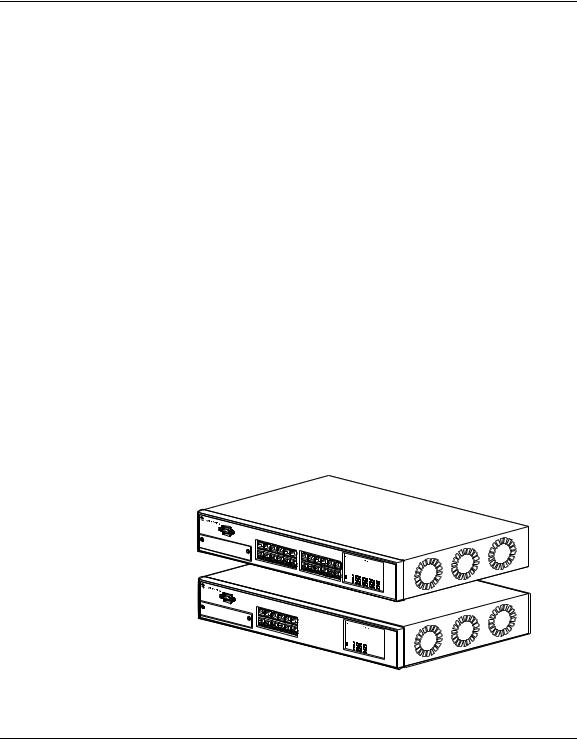
There are two versions of the BayStack 350 10/100/1000 Series Switches: the BayStack 350-24T switch and the BayStack 350-12T switch. This guide describes the features, uses, and installation procedures for the two versions. (Unless otherwise specified, the terms “BayStack 350 switch” and “switch” refer to both switch versions.)
BayStack 350 switches include a dedicated Uplink Module slot for attaching optional media dependent adapters (MDAs) that support a range of media types, including gigabit Ethernet. Installation instructions are included with each MDA (see your Bay Networks sales representative for ordering information).
For more information about the MDAs, refer to Appendix B, “Media Dependent Adapters.”
Before You Begin
This guide is intended for network installers and system administrators who are responsible for installing, configuring, or maintaining networks.
This guide assumes that you have the following background:
•Understanding of the transmission and management protocols used on your network
304376-B Rev 00 |
xix |

Using the BayStack 350 10/100/1000 Series Switch
Organization
This guide has four chapters, six appendixes, and an index:
If you want to: |
Go to: |
|
|
Learn about the BayStack 350 switch and its key features |
Chapter 1 |
Install the BayStack 350 switch on a flat surface or in a |
Chapter 2 |
19-inch equipment rack, and verify its operation |
|
Connect to the BayStack 350 switch Console/Comm Port |
Chapter 3 |
and learn how to use the console interface (CI) menus to |
|
configure and manage the switch |
|
Troubleshoot and diagnose problems with the BayStack |
Chapter 4 |
350 switch |
|
View operational and environmental specifications that |
Appendix A |
apply to the BayStack 350 switch |
|
Learn about optional media dependent adapters (MDAs) |
Appendix B |
you can use with the BayStack 350 switch |
|
Learn about Quick-Step flowcharts for using the BayStack |
Appendix C |
350 switch features |
|
Learn more about the BayStack 350 switch connectors |
Appendix D |
(ports) and pin assignments |
|
View a listing of the factory default settings for the |
Appendix E |
BayStack 350 switch |
|
View a sample BootP configuration file |
Appendix F |
View an alphabetical listing of the topics and subtopics in |
Index |
this guide, with cross-references to relevant information |
|
|
|
xx |
304376-B Rev 00 |
Preface
Text Conventions
This guide uses the following text conventions:
bold text |
Indicates command names and options and text that |
|
you need to enter. |
|
Example: Enter show ip {alerts | routes}. |
|
Example: Use the dinfo command. |
italic text |
Indicates file and directory names, new terms, book |
|
titles, and variables in command syntax descriptions. |
|
Where a variable is two or more words, the words are |
|
connected by an underscore. |
|
Example: If the command syntax is: |
|
show at <valid_route> |
|
valid_route is one variable and you substitute one value |
|
for it. |
screen text |
Indicates system output, for example, prompts and |
|
system messages. |
|
Example: Set Bay Networks Trap Monitor Filters |
[Enter] |
Named keys in text are enclosed in square brackets. |
|
The notation [Enter] is used for the Enter key and the |
|
Return key. |
[Ctrl]-C |
Two or more keys that must be pressed simultaneously |
|
are shown in text linked with a hyphen (-) sign. |
Acronyms
This guide uses the following acronyms:
AUI |
attachment unit interface |
BootP |
Bootstrap Protocol |
|
(continued) |
|
|
304376-B Rev 00 |
xxi |

Using the BayStack 350 10/100/1000 Series Switch
CSMA/CD |
carrier sense multiple access/collision detection |
IP |
Internet Protocol |
MAC |
media access control |
MDI-X |
medium dependent interface crossover |
PPP |
Point-to-Point Protocol |
SNMP |
Simple Network Management Protocol |
Related Publications
For more information about using the BayStack 350 switch, refer to the following publication:
•Installing Media Dependent Adapters (MDA)s (Bay Networks part number 302403-B)
Describes how to install optional media dependent adapters (MDA)s to your BayStack 350 switch.
You can now print Bay Networks technical manuals and release notes free, directly from the Internet. Go to support.baynetworks.com/library/tpubs/. Find the Bay Networks product for which you need documentation. Then locate the specific category and model or version for your hardware or software product. Using Adobe Acrobat Reader, you can open the manuals and release notes, search for the sections you need, and print them on most standard printers. You can download Acrobat Reader free from the Adobe Systems Web site, www.adobe.com.
You can purchase Bay Networks documentation sets, CDs, and selected technical publications through the Bay Networks Collateral Catalog. The catalog is located on the World Wide Web at support.baynetworks.com/catalog.html and is divided into sections arranged alphabetically:
•The “CD ROMs” section lists available CDs.
•The “Guides/Books” section lists books on technical topics.
•The “Technical Manuals” section lists available printed documentation sets.
Make a note of the part numbers and prices of the items that you want to order. Use the “Marketing Collateral Catalog description” link to place an order and to print the order form.
xxii |
304376-B Rev 00 |

Preface
How to Get Help
For product assistance, support contracts, information about educational services, and the telephone numbers of our global support offices, go to the following URL:
http://www.baynetworks.com/corporate/contacts/
In the United States and Canada, you can dial 800-2LANWAN for assistance.
304376-B Rev 00 |
xxiii |
Chapter 1
BayStack 350 10/100/1000 Series Switches
This chapter introduces the BayStack 350 10/100/1000 Series Switches and covers the following topics:
•Physical description
•Summary of features
•Network configuration examples
•Overview of main features
Physical Description
There are two versions of the BayStack 350 switch: the BayStack 350-24T switch and the BayStack 350-12T switch (Figure 1-1).
BayStack 350-24T


 3
3

BayStack 350-12T


 3
3


BS35001A
Figure 1-1. BayStack 350 10/100/1000 Series Switches
304376-B Rev 00 |
1-1 |

Using the BayStack 350 10/100/1000 Series Switch
Front-Panel
Figure 1-2 shows the front-panel of the BayStack 350-24T switch and the BayStack 350-12T switch. Descriptions of the front-panel components follow the figures.
For a description of the components located on the back-panel of the BayStack 350 switch, see “ Back-Panel” on page 1-6.
1 |
|
|
|
2 |
|
|
|
|
|
3 |
|
|
|
|
4 |
Comm Port |
|
|
|
|
|
|
|
|
|
|
|
|
|
|
3 |
|
|
|
|
|
|
|
|
|
|
|
|
|
|
|
|
|
|
|
|
1 |
3 |
5 |
7 |
9 |
11 |
13 |
15 |
17 |
19 |
21 |
23 |
Uplink/Expansion Module |
25 |
26 |
27 |
28 |
|
|
|
|
|
|
|
|
|
|
|
|
|
|
|
|
|
|
|
|
|
|
|
|
|
|
10/100 |
|
|
|
|
|
|
|
|
|
|
|
|
|
|
|
Pwr |
|
|
|
|
|
|
|
|
|
|
|
|
|
|
|
Activity |
|
|
|
|
|
|
|
|
|
|
|
|
|
|
|
Status |
|
|
|
|
|
|
|
|
|
|
|
|
|
|
|
10/100 |
|
|
|
|
|
|
|
|
|
|
|
|
|
|
|
Activity |
|
|
|
|
2 |
4 |
6 |
8 |
10 |
12 |
14 |
16 |
18 |
20 |
22 |
24 |
|
|
|
|
|
|
|
|
BayStack 350-24T |
|
|
|
|
|||
1 |
|
|
|
2 |
|
|
3 |
|
|
|
|
|
|
|
4 |
Comm Port |
|
|
|
|
|
|
|
|
|
|
|
|
|
|
|
|
|
|
|
|
|
|
|
|
|
|
|
|
|
|
3 |
|
|
|
|
1 |
3 |
5 |
7 |
9 |
11 |
|
|
|
|
|
|
Uplink/Expansion Module |
13 |
14 |
15 |
16 |
|
|
|
|
|
|
|
|
|
|
|
|
|
|
|
|
|
|
|
|
|
|
|
|
|
|
10/100 |
|
|
|
|
|
|
|
|
|
|
|
|
|
|
|
Pwr |
|
|
|
|
|
|
|
|
|
|
|
|
|
|
|
Activity |
|
|
|
|
|
|
|
|
|
|
|
|
|
|
|
Status |
|
|
|
|
|
|
|
|
|
|
|
|
|
|
|
10/100 |
|
|
|
|
|
|
|
|
|
|
|
|
|
|
|
Activity |
|
|
|
|
2 |
4 |
6 |
8 |
10 |
12 |
|
|
|
|
|
|
BayStack 350-12T
1 = Comm Port
2 = Uplink/Expansion slot
3 = 10BASE-T/100BASE-TX port connectors
4 = LED display panel
BS35002A
Figure 1-2. Front-Panel Components
1-2 |
304376-B Rev 00 |

BayStack 350 10/100/1000 Series Switches
Comm Port
The Comm Port (also referred to as the Console/Comm Port) allows you to access the console interface (CI) screens and customize your network using the supplied menus and screens (see Chapter 3, “Using the Console Interface”).
The Console/Comm Port is a DB-9, RS-232-D male serial port connector. You can use this connector to connect a management station or console/terminal to the switch by using a straight-through DB-9 to DB-9 standard serial port cable (see “Connecting the Console/Comm Port” on page 2-10).
Note: The Console/Comm Port is configured as a data communications equipment (DCE) connector. Ensure that your RS-232 cable pinouts are configured for DCE connections (see “DB-9 (RS-232-D) Console/Comm Port Connector” on page D-5).
The console port runs at 9600 baud and uses eight data bits, one stop bit, and no parity as the communications format, with flow control set to disabled.
Uplink/Expansion Slot
The Uplink/Expansion slot allows you to attach optional media dependent adapters (MDAs) that support a range of media types (see Appendix B, “Media Dependent Adapters” for more information about MDA types available from Bay Networks).
10BASE-T/100BASE-TX Port Connectors
BayStack 350 switches use 10BASE-T/100BASE-TX RJ-45 (8-pin modular) port connectors.
Note: The RJ-45 port connectors on BayStack 450 switches manufactured prior to December 1998 are numbered 1 to 12 and 13 to 24, in succession from left to right. Later units use port connectors that are configured with one or two dual, six-port groups, numbered 1 to 12 and 13 to 24. The top rows are odd numbered and the bottom rows are even numbered (see Figure 1-2 on
page 1-2). Port-specific examples in this guide show the appropriate port connections when required; other examples apply to both versions.
304376-B Rev 00 |
1-3 |

Using the BayStack 350 10/100/1000 Series Switch
All BayStack 350 switches are shipped with port connectors configured as MDI-X (media-dependent interface-crossover). These ports connect over straight cables to the network interface controller (NIC) card in a node or server, similar to a conventional Ethernet repeater hub. If you are connecting to another Ethernet hub or Ethernet switch, you need a crossover cable unless an MDI connection exists on the associated port of the attached device (see “MDI and MDI-X Devices” on page D-2).
The switches use autosensing ports that are designed to operate at 10 Mb/s or at 100 Mb/s, depending on the connecting device. These ports support the IEEE 802.3u autonegotiation standard, which means that when a port is connected to another device that also supports the IEEE 802.3u standard, the two devices negotiate the best speed and duplex mode of operation.
The switch ports also support halfand full-duplex mode operation (see “Connecting the 10BASE-T/100BASE-TX Ports” on page 2-9).
The switch uses 10BASE-T/100BASE-TX RJ-45 port connectors to connect to 10 Mb/s or 100 Mb/s Ethernet segments or nodes.
Note: Use only Category 5 copper unshielded twisted pair (UTP) cable connections when connecting 10BASE-T/100BASE-TX ports.
See Appendix D, “Connectors and Pin Assignments” for more information about the RJ-45 port connectors.
LED Display Panel
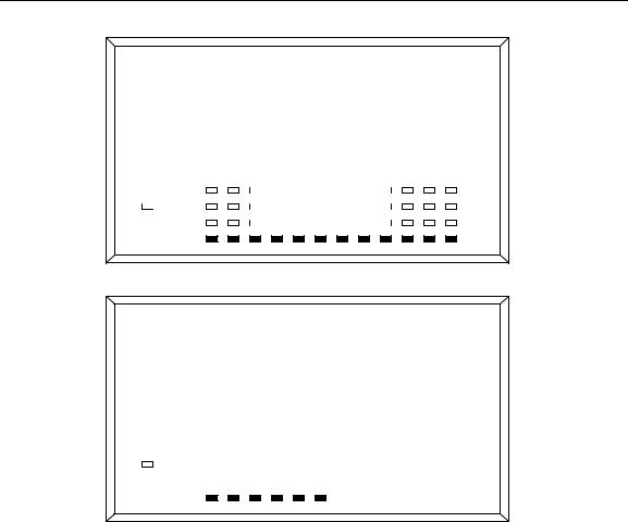
Figure 1-3 shows the LED display panels for the BayStack 350-24T and the BayStack 350-12T models.
Note: The LED display panel configuration for your switch may be different than shown in Figure 1-3, depending on the date of manufacturing (see the note in “ 10BASE-T/100BASE-TX Port Connectors” on page 1-3).
Refer to Table 1-1 for a description of the LEDs.
1-4 |
304376-B Rev 00 |
BayStack 350 10/100/1000 Series Switches
BayStack 350-24T Switch
|
|
|
1 |
|
3 |
|
5 |
|
7 |
|
9 |
|
11 |
13 |
|
15 |
|
17 |
|
19 |
|
21 |
|
23 |
10/100 |
|
|
|
|
|
|
|
|
|
|
|
|
|
|
|
|
|
|
|
|
|
|
|
|
|
|
|
|
Pwr |
|
|
|
|
|
|
|
|
|
|
|
|
|
|
|
|
|
|
|
|
|
|
|
Activity |
||
|
|
|
|
|
|
|
|
|
|
|
|
|
|
|
|
|
|
|
|
|
|
|
|
|
|
|
Status |
2 |
|
4 |
|
6 |
|
8 |
|
10 |
|
12 |
14 |
|
16 |
|
18 |
|
20 |
|
22 |
|
24 |
10/100 |
|||
|
|
|
|
|
|
|
|
|
|
|
|
|
|
|
|
|
|
|
|
|
|
|
|
|
|
|
Activity
BayStack 350-24T
BayStack 350-12T Switch
|
|
|
1 |
|
3 |
|
5 |
|
7 |
|
9 |
|
11 |
10/100 |
Pwr |
|
|
|
|
|
|
|
|
|
|
|
Activity |
||
|
|
|
|
|
|
|
|
|
|
|
|
|
|
|
Status |
2 |
|
4 |
|
6 |
|
8 |
|
10 |
|
12 |
10/100 |
||
|
|
|
|
|
|
|
|
|
|
|
|
|
|
|
Activity
BayStack 350-12T
BS35003A
Figure 1-3. LED Display Panel
Table 1-1. |
LED Descriptions |
|
|
|
|
|
|
|
|
Label |
Type |
Color |
State |
Meaning |
|
|
|
|
|
Pwr |
Power status |
Green |
On |
DC power is available to the switch’s internal circuitry. |
|
|
|
Off |
No AC power to switch or power supply failed. |
|
|
|
|
(continued) |
|
|
|
|
|
304376-B Rev 00 |
|
|
1-5 |
|
Using the BayStack 350 10/100/1000 Series Switch
Table 1-1. |
LED Descriptions (continued) |
|||
|
|
|
|
|
Label |
Type |
Color |
State |
Meaning |
|
|
|
|
|
Status |
System status |
Green |
On |
Self-test passed successfully and switch is operational. |
|
|
|
Blinking |
A nonfatal error occurred during the self-test. |
|
|
|
Off |
The switch failed the self-test. |
10/100 |
10/100 Mb/s |
Green |
On |
The corresponding port is set to operate at 100 Mb/s and |
|
port speed |
|
|
the link is good. |
|
indicator |
|
|
|
|
|
Green |
Blinking |
The corresponding port has been disabled by software. |
|
|
Amber |
On |
The corresponding port is set to operate at 10 Mb/s and |
|
|
|
|
the link is good. |
|
|
Amber |
Blinking |
The corresponding port has been disabled by software. |
|
|
|
Off |
The link connection is bad or there is no connection to |
|
|
|
|
this port. |
Activity |
Port activity |
Green |
Blinking |
Indicates network activity for the corresponding port. A |
|
|
|
|
high level of network activity can cause the LEDs to |
|
|
|
|
appear to be on continuously. |
|
|
|
|
|
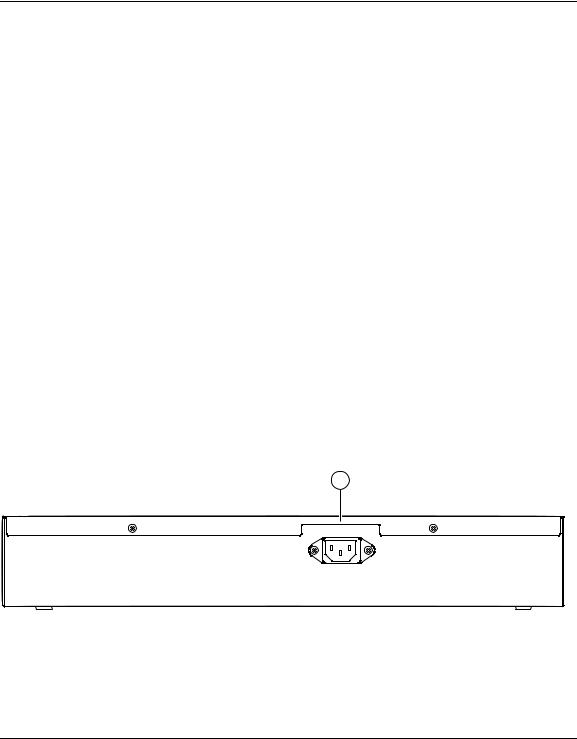
Back-Panel
This section describes the BayStack 350 switch back-panel components (Figure 1-4). Descriptions of the back-panel components follow the figure.
1
100-240V
47-63Hz~
1 = AC power receptacle |
BS35004A |
|
Figure 1-4. Back-Panel Components
1-6 |
304376-B Rev 00 |
Loading...